EP2078574A1 - Roughing mill with inclined cutting edge - Google Patents
Roughing mill with inclined cutting edge Download PDFInfo
- Publication number
- EP2078574A1 EP2078574A1 EP08021651A EP08021651A EP2078574A1 EP 2078574 A1 EP2078574 A1 EP 2078574A1 EP 08021651 A EP08021651 A EP 08021651A EP 08021651 A EP08021651 A EP 08021651A EP 2078574 A1 EP2078574 A1 EP 2078574A1
- Authority
- EP
- European Patent Office
- Prior art keywords
- roughing
- milling
- period
- cutting edge
- roughing cutter
- Prior art date
- Legal status (The legal status is an assumption and is not a legal conclusion. Google has not performed a legal analysis and makes no representation as to the accuracy of the status listed.)
- Granted
Links
- 238000003801 milling Methods 0.000 claims abstract description 47
- 238000011161 development Methods 0.000 description 4
- 230000018109 developmental process Effects 0.000 description 4
- 238000000227 grinding Methods 0.000 description 2
- 230000003247 decreasing effect Effects 0.000 description 1
- 238000009795 derivation Methods 0.000 description 1
- 238000012986 modification Methods 0.000 description 1
- 230000004048 modification Effects 0.000 description 1
- 239000007787 solid Substances 0.000 description 1
Images


Classifications
-
- B—PERFORMING OPERATIONS; TRANSPORTING
- B23—MACHINE TOOLS; METAL-WORKING NOT OTHERWISE PROVIDED FOR
- B23C—MILLING
- B23C5/00—Milling-cutters
- B23C5/02—Milling-cutters characterised by the shape of the cutter
- B23C5/10—Shank-type cutters, i.e. with an integral shaft
-
- B—PERFORMING OPERATIONS; TRANSPORTING
- B23—MACHINE TOOLS; METAL-WORKING NOT OTHERWISE PROVIDED FOR
- B23C—MILLING
- B23C2210/00—Details of milling cutters
- B23C2210/08—Side or top views of the cutting edge
- B23C2210/088—Cutting edges with a wave form
-
- B—PERFORMING OPERATIONS; TRANSPORTING
- B23—MACHINE TOOLS; METAL-WORKING NOT OTHERWISE PROVIDED FOR
- B23C—MILLING
- B23C2210/00—Details of milling cutters
- B23C2210/40—Flutes, i.e. chip conveying grooves
-
- B—PERFORMING OPERATIONS; TRANSPORTING
- B23—MACHINE TOOLS; METAL-WORKING NOT OTHERWISE PROVIDED FOR
- B23C—MILLING
- B23C2220/00—Details of milling processes
- B23C2220/60—Roughing
Definitions
- the invention relates to a roughing cutter with bevelled cutting edge according to the preamble of claim 1.
- Such roughing cutter has a cylindrical tool shank, which is clamped at its one, upper end in a milling machine. From its lower end extends in the direction of the upper end of the tool shank a milling area, which has at least one, usually about four, located in the periphery of the milling cutter and extending in a spiral milling surfaces. These milling surfaces are provided with a longitudinal direction of the screw shaft undulating roughing teeth with a cutting edge, wherein the cutting edge is chamfered over its entire length and substantially over the entire height of the wave-shaped roughing teeth.
- Such a roughing cutter manufactured by the applicant has been marketed by the Hoffmann Group since August 1995 as a solid carbide roughing cutter HPC.
- This known roughing cutter has four or five running in a screw milling surfaces; see. the catalog of the company Hoffmann Group 2005/2006, page 244.
- a roughing cutter which is provided in the region of the cutting edge with a chamfer, wherein the chamfer extends over at least the entire height of the wave crests of the wave-like roughing teeth.
- the bevel is, as in the above roughing cutter by a single flat grinding made along the cutting edge.
- This chamfered cutting edge is followed, in the forward direction of the milling cutter, by a chip groove into which the milled chips dive during milling of a workpiece and are removed in the direction of the upper end of the roughing cutter.
- the chips When milling a workpiece, the chips are discharged substantially at a right angle to the cutting edge and transported into the chip groove. The chips then occur in this direction on the cutting edge of the opposite wall of the chip groove, where they must then be deflected abruptly to be discharged in the chip groove upwards towards the chuck end.
- the invention has for its object to provide a roughing cutter with a stable by the tapered portion cutting edge, in which the chip removal of the milled chips is improved, so that virtually no Spanklemmer occur.
- the chamfered portion of the cutting edge in the longitudinal direction thereof is serrated with alternate serrations and valleys.
- the cutting edge of the milling surface seen in the longitudinal direction of the roughing cutter, reset in a wave trough and offset in a wave crest forward.
- the chip is pushed down into the chip groove, i. H. in the direction of the front side of the roughing cutter, steered and then discharged in a smooth smooth deflection in the upward direction. In this way, chip breakers can be avoided almost completely. Clogging of the chip groove is prevented by this design of the roughing cutter.
- the advantage is maintained that the chamfer of the cutting edge reinforces and stabilizes it so that break-outs of the cutting edge are avoided.
- the period of the wave-grinding i. H. the distance between two consecutive wave crests, constant.
- the period of serration covers several periods of the wave-like roughing toothing, z. B. three to four periods. An exact geometric assignment of the periods of serration and roughing is not necessary.
- the roughing cutter is a milling cutter having a plurality of milling surfaces each running in a screw thread
- the wave crests and wave troughs of the serrated edge, in the longitudinal direction of the roughing cutter lie in a common generating line of the roughing cutter.
- the wave crests and wave troughs of the serrated edge of adjacent milling surfaces can each be offset from each other by a part of the period of the serrated edge in the circumferential direction of the tool shank.
- this offset corresponds to the period of the wave cut divided by the number of milling surfaces.
- this offset is one quarter of the period of the serration.
- This offset of the period of the serration of successive milling surfaces preferably extends in one direction.
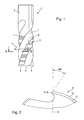
- a roughing cutter 1 has a cylindrical tool shank 2, which with its in FIG. 1 upper end is clamped in a milling machine, not shown here.
- the adjoining the smooth cylindrical tool shank 2 area of the roughing mill 1 is formed as a milling section 3, in this case with four angularly along the circumference of the milling cutter by 90 ° offset milling surfaces 4, which are located in the periphery of the milling cutter 1 and band-shaped from a the clamping end of the tool shank 2 opposite end face 5 each extend in a helical gear in the direction of the upper end of the milling section 3.
- the milling surfaces 4 each have a cutting edge 6. Between adjacent milling surfaces 4 each groove-shaped chip grooves 7 are located, through which the costs incurred during milling chips are removed.
- the milling surfaces 4 terminate in the end face 5 of the milling cutter 1 in each case in a cutting edge 8.
- Each milling surface 4 is provided with a wave-shaped roughing toothing 11, which has successive wave peaks 12 and wave troughs 13.
- the crests of the crests 12 are shown as solid lines, the baselines of the crests 13 are shown as dashed lines.
- the crests of the wave mountains and the baselines of the troughs start off a vertical roughing cutter about horizontal, as in FIG. 1 shown schematically.
- the cutting edge 6 of the roughing toothing 11 is, as shown schematically in FIG. 2 shown with a positive rake angle SW against a diameter line D of the roughing cutter chamfered.
- This bevelled area is designated 14 in the figures.
- the beveled portion 14 of the cutting edge 6 is formed in the longitudinal direction as a serrated edge of alternating mountains 15 and valleys 16; see.
- This serrated edge has a period P as in the Figures 3 and 4 indicated.
- This period P is significantly greater than the period of the roughing teeth, usually three to six times larger, so that the period of the serrated edge 14 always covers several periods of the wave-like roughing teeth 11.
- the serration of the cutting edge as best of the Figures 3 and 4 shows, the cutting edge 6 of the roughing cutter periodically moved forward or back. This serrated edge creates a similar function as an unequally split cutting edge. At the same time, the cutting edge is very stable, so that no breaks occur.
- FIG. 3 schematically shows the developments of two adjacent screw threads of a roughing cutter, which has a plurality of milling surfaces, for example, four milling surfaces.
- the ridges of the wave crests 12 of the serrations of the individual screw threads lie exactly on a common generating line of the roughing cutter.
- the common generatrix is indicated schematically by dash-dotted lines and provided with the reference numeral 17.
- the periods of the corrugations of adjacent screw threads are each offset by one n-th of the period P of the serration, preferably in a direction as indicated by the arrow 18.
- the periods of the serrations of adjacent screw gears are offset from each other by a quarter period.
- the surface line 17 of the wave crest 15 of the first flight is thus offset by an n-th, ie a quarter of the period of the serration with respect to the surface line 17 ', which passes through the crest of the second flight; Similarly, the generatrix 17 '', which passes through the crest of the third screw, a quarter of a period from the generatrix 17 'offset, etc.
Abstract
Description
Die Erfindung bezieht sich auf einen Schruppfräser mit abgeschrägter Schneidkante gemäß dem Oberbegriff des Anspruchs 1.The invention relates to a roughing cutter with bevelled cutting edge according to the preamble of claim 1.
Ein solcher Schruppfräser weist einen zylindrischen Werkzeugschaft auf, der an seinem einen, oberen Ende in eine Fräsmaschine einspannbar ist. Von seinem unteren Ende erstreckt sich in Richtung auf das obere Ende des Werkzeugschafts ein Fräsbereich, der zumindest eine, üblicherweise etwa vier, im Umfang des Fräsers gelegene und in einem Schraubengang verlaufende Fräsflächen aufweist. Diese Fräsflächen sind mit einer in Längsrichtung des Schraubenganges wellenförmig verlaufenden Schruppverzahnung mit einer Schneidkante versehen, wobei die Schneidkante über ihre gesamte Länge und im Wesentlichen über die gesamte Höhe der wellenförmigen Schruppverzahnung abgeschrägt ist.Such roughing cutter has a cylindrical tool shank, which is clamped at its one, upper end in a milling machine. From its lower end extends in the direction of the upper end of the tool shank a milling area, which has at least one, usually about four, located in the periphery of the milling cutter and extending in a spiral milling surfaces. These milling surfaces are provided with a longitudinal direction of the screw shaft undulating roughing teeth with a cutting edge, wherein the cutting edge is chamfered over its entire length and substantially over the entire height of the wave-shaped roughing teeth.
Ein solcher, von der Anmelderin hergestellter Schruppfräser wird von der Firma Hoffmann Group seit August 1995 als VHM-Schruppfräser HPC vertrieben. Dieser bekannte Schruppfräser weist vier beziehungsweise fünf in einem Schraubengang verlaufende Fräsflächen auf; vgl. den Katalog der Firma Hoffmann Group 2005/2006, Seite 244.Such a roughing cutter manufactured by the applicant has been marketed by the Hoffmann Group since August 1995 as a solid carbide roughing cutter HPC. This known roughing cutter has four or five running in a screw milling surfaces; see. the catalog of the company Hoffmann Group 2005/2006, page 244.
In der
Der Vorteil einer solchen abgeschrägten Schneidkante liegt unter anderem darin, dass die Schneidkante stabilisiert wird, und insbesondere in dem Bereich der Wellenberge der Schneidkante Ausbrechungen der Schneidkante beim Fräsen vermieden werden.The advantage of such a beveled cutting edge is, inter alia, that the cutting edge is stabilized, and in particular in the area of the peaks of the cutting edge, breakages of the cutting edge during milling are avoided.
Beim Fräsen eines Werkstücks werden die Späne im Wesentlichen in einem rechten Winkel zur Schneidkante abgegeben und in die Spanrille transportiert. Die Späne treten dann in dieser Richtung auf die der Schneidkante gegenüber liegende Wand der Spanrille auf, wo sie dann abrupt umgelenkt werden müssen, um in der Spanrille nach oben in Richtung auf das Einspannende abgeführt zu werden.When milling a workpiece, the chips are discharged substantially at a right angle to the cutting edge and transported into the chip groove. The chips then occur in this direction on the cutting edge of the opposite wall of the chip groove, where they must then be deflected abruptly to be discharged in the chip groove upwards towards the chuck end.
Durch eine solche Ableitung der Späne kann es in den Spanrillen des Schruppfräsers durchaus zu sogenannten Spanklemmern führen, sodass die abgefrästen Späne nicht glatt abgeführt werden und die Spanrille sozusagen verstopft.By such a derivation of the chips, it may well lead to so-called chip clamps in the chip grooves of the roughing cutter, so that the milled chips are not smoothly dissipated and the chip groove so to speak clogged.
Der Erfindung liegt die Aufgabe zugrunde, einen Schruppfräser mit einer durch den abgeschrägten Bereich stabilen Schneidkante anzugeben, bei dem die Spanabfuhr der abgefrästen Späne verbessert wird, sodass praktisch keine Spanklemmer auftreten.The invention has for its object to provide a roughing cutter with a stable by the tapered portion cutting edge, in which the chip removal of the milled chips is improved, so that virtually no Spanklemmer occur.
Diese Aufgabe ist gemäß der Erfindung durch die Merkmale des Anspruchs 1 gelöst.This object is achieved according to the invention by the features of claim 1.
Demgemäß ist der abgeschrägte Bereich der Schneidkante in deren Längsrichtung mit einem Wellenschliff aus abwechselnd Bergen und Tälern versehen.Accordingly, the chamfered portion of the cutting edge in the longitudinal direction thereof is serrated with alternate serrations and valleys.
Durch einen solchen Wellenschliff wird die Schneidkante der Fräsfläche, in Längsrichtung des Schruppfräsers gesehen, in einem Wellental zurückgesetzt und in einem Wellenberg nach vorne versetzt. Sobald ein Span des zu fräsenden Werkstückes den Wellenschliff nach einem Wellenberg verlässt, wird der Span in die Spanrille nach unten, d. h. in Richtung auf die Stirnseite des Schruppfräsers, gelenkt und dann in einem zügigen glatten Umlenkvorgang in Richtung nach oben abgeführt. Auf diese Weise können Spanklemmer praktisch vollständig vermieden werden. Eine Verstopfung der Spanrille wird durch diese Ausgestaltung des Schruppfräsers verhindert.By such a serrated edge, the cutting edge of the milling surface, seen in the longitudinal direction of the roughing cutter, reset in a wave trough and offset in a wave crest forward. As soon as a chip of the workpiece to be milled leaves the serrated edge after a wave crest, the chip is pushed down into the chip groove, i. H. in the direction of the front side of the roughing cutter, steered and then discharged in a smooth smooth deflection in the upward direction. In this way, chip breakers can be avoided almost completely. Clogging of the chip groove is prevented by this design of the roughing cutter.
Gleichzeitig wird der Vorteil beibehalten, dass durch die Abschrägung der Schneidkante diese verstärkt und stabilisiert wird, sodass Ausbrechungen der Schneidkante vermieden werden.At the same time, the advantage is maintained that the chamfer of the cutting edge reinforces and stabilizes it so that break-outs of the cutting edge are avoided.
Gemäß einer bevorzugten Ausführungsform der Erfindung ist die Periode des Wellenschliffs, d. h. der Abstand zwischen zwei aufeinander folgenden Wellenbergen, konstant. Es ist jedoch durchaus möglich, die Periode des Wellenschliffs zu variieren, zum Beispiel indem die Periode des Wellenschliffs von der Stirnseite des Fräsers beginnend sukzessive in Richtung auf das obere Einspannende des Schruppfräsers verringert wird.According to a preferred embodiment of the invention, the period of the wave-grinding, i. H. the distance between two consecutive wave crests, constant. However, it is quite possible to vary the period of serration, for example, by decreasing the period of serration starting from the end face of the mill gradually toward the upper chuck end of the roughing mill.
Gemäß einer bevorzugten Ausführungsform der Erfindung überdeckt die Periode des Wellenschliffs mehrere Perioden der wellenförmigen Schruppverzahnung, z. B. drei bis vier Perioden. Eine exakte geometrische Zuordnung der Perioden des Wellenschliffs und der Schruppverzahnung ist nicht notwendig.According to a preferred embodiment of the invention, the period of serration covers several periods of the wave-like roughing toothing, z. B. three to four periods. An exact geometric assignment of the periods of serration and roughing is not necessary.
Wenn der Schruppfräser ein Fräser mit mehreren jeweils in einem Schraubengang verlaufenden Fräsflächen ist, so liegen gemäß einer bevorzugten Ausführungsform der Erfindung die Wellenberge und Wellentäler des Wellenschliffs, in Längsrichtung des Schruppfräsers, in einer gemeinsamen Mantellinie des Schruppfräsers.If the roughing cutter is a milling cutter having a plurality of milling surfaces each running in a screw thread, according to a preferred embodiment of the invention, the wave crests and wave troughs of the serrated edge, in the longitudinal direction of the roughing cutter, lie in a common generating line of the roughing cutter.
Alternativ hierzu können die Wellenberge und Wellentäler des Wellenschliffs benachbarter Fräsflächen, wiederum in Längsrichtung des Schruppfräsers gesehen, jeweils um einen Teil der Periode des Wellenschliffs in Umfangrichtung des Werkzeugschafts gegeneinander versetzt werden. Vorzugsweise entspricht dieser Versatz der Periode des Wellenschliffs geteilt durch die Anzahl der Fräsflächen. Wenn der Schruppfräser somit vier in Schraubengängen verlaufende Fräsflächen aufweist, so beträgt dieser Versatz jeweils ein Viertel der Periode des Wellenschliffs.Alternatively, the wave crests and wave troughs of the serrated edge of adjacent milling surfaces, again viewed in the longitudinal direction of the roughing cutter, can each be offset from each other by a part of the period of the serrated edge in the circumferential direction of the tool shank. Preferably, this offset corresponds to the period of the wave cut divided by the number of milling surfaces. Thus, if the roughing cutter has four helical milling surfaces, this offset is one quarter of the period of the serration.
Bevorzugt verläuft dieser Versatz der Periode des Wellenschliffs aufeinander folgender Fräsflächen in einer Richtung.This offset of the period of the serration of successive milling surfaces preferably extends in one direction.
Die Erfindung ist in Ausführungsbeispielen anhand der Zeichnung näher erläutert. In dieser stellen dar:
-
Figur 1 eine Ansicht eines Schruppfräsers gemäß der Erfindung mit vier schraubenförmig verlaufenden Fräsflächen, wobei die Schneidkanten dieser Fräsflächen jeweils durch einen Wellenschliff abgeschrägt sind; -
Figur 2Figur 1 längs II-II im Bereich der durch den Wellenschliff abgeschrägten Schneidkante; -
Figur 3 -
Figur 4
-
FIG. 1 a view of a roughing cutter according to the invention with four helical milling surfaces, wherein the cutting edges of these Fräsflächen are each beveled by a serration; -
FIG. 2 a partial cross section through the roughing cutter according toFIG. 1 along II-II in the area of the serrated beveled cutting edge; -
FIG. 3 schematically a development of a part of the roughing cutter in the region of the cutting edges of two adjacent Milling surfaces, the mountains and valleys of the serrated edge are located at both cutting edges each in a common generating line of the roughing cutter; and -
FIG. 4 a development of a part of a roughing cutter in the range of three milling surfaces, in which the period of the serrated edge is offset by a portion of the period of the serration, in this case a quarter period.
Ein Schruppfräser 1 weist einen zylindrischen Werkzeugschaft 2 auf, der mit seinem in
Die Fräsflächen 4 enden in der Stirnseite 5 des Fräsers 1 jeweils in einer Schneide 8.The
Jede Fräsfläche 4 ist mit einer wellenförmigen Schruppverzahnung 11 versehen, die aufeinander folgende Wellenberge 12 und Wellentäler 13 aufweist. In
Die Schneidkante 6 der Schruppverzahnung 11 ist, wie schematisch in
Dieser abgeschrägte Bereich ist in den Figuren mit 14 bezeichnet. Der abgeschrägte Bereich 14 der Schneidkante 6 ist in deren Längsrichtung als Wellenschliff aus abwechselnd Bergen 15 und Tälern 16 ausgebildet; vgl. hierzu die schematischen Abwicklungen in den
Durch diesen Wellenschliff werden die abgefrästen Späne erst nach unten in die Spanrillen 7 geführt, wonach der Span glatt umgelenkt und dann nach oben abgeführt wird.As a result of this serrated edge, the milled chips are first guided downwards into the
In
Gemäß einer anderen Ausführungsform, die schematisch in
Modifikationen und Abänderungen der beschriebenen Erfindung sind für einen Fachmann natürlich möglich; die Erfindung wird jedoch durch die anhängenden Ansprüche definiert.Modifications and variations of the invention described are of course possible for a person skilled in the art; However, the invention is defined by the appended claims.
Claims (8)
Applications Claiming Priority (1)
| Application Number | Priority Date | Filing Date | Title |
|---|---|---|---|
| DE202008000350U DE202008000350U1 (en) | 2008-01-09 | 2008-01-09 | Roughing cutter with bevelled cutting edge |
Publications (2)
| Publication Number | Publication Date |
|---|---|
| EP2078574A1 true EP2078574A1 (en) | 2009-07-15 |
| EP2078574B1 EP2078574B1 (en) | 2011-03-09 |
Family
ID=39432282
Family Applications (1)
| Application Number | Title | Priority Date | Filing Date |
|---|---|---|---|
| EP08021651A Active EP2078574B1 (en) | 2008-01-09 | 2008-12-12 | Roughing mill with inclined cutting edge |
Country Status (3)
| Country | Link |
|---|---|
| EP (1) | EP2078574B1 (en) |
| AT (1) | ATE500914T1 (en) |
| DE (2) | DE202008000350U1 (en) |
Cited By (7)
| Publication number | Priority date | Publication date | Assignee | Title |
|---|---|---|---|---|
| CN103111820A (en) * | 2013-03-20 | 2013-05-22 | 沈阳飞机工业(集团)有限公司 | Machining technology of tooth profile of milling cutter with wave-shaped cutter edge |
| DE202012008940U1 (en) | 2011-09-20 | 2013-06-19 | Jetmir Bejtulai | milling tool |
| CN103381501A (en) * | 2012-05-03 | 2013-11-06 | 李仕清 | Helix milling cutter with compound blade |
| CN103706860A (en) * | 2012-10-01 | 2014-04-09 | 李仕清 | Helix milling cutter provided with compound blade |
| EP2745969A1 (en) | 2012-12-19 | 2014-06-25 | Marco Näf | Milling tool |
| CN103878430A (en) * | 2014-03-04 | 2014-06-25 | 苏州瑞森硬质合金有限公司 | Helical wave edge milling cutter |
| EP2868413B1 (en) | 2013-10-31 | 2018-09-12 | Union Tool Co. | Hard-coated cutting tool |
Families Citing this family (3)
| Publication number | Priority date | Publication date | Assignee | Title |
|---|---|---|---|---|
| JP5289617B1 (en) * | 2011-10-06 | 2013-09-11 | オーエスジー株式会社 | tool |
| DE102013002730A1 (en) | 2013-02-16 | 2014-08-21 | Hans-Jürgen Gittel | Milling tool for processing workpieces, has roughing gearing unit that intersects with simple gearing unit and arranged on radial larger flight circle, where tool is resharpened typically in splinter space and/or at chip surface |
| DE102021122033A1 (en) | 2021-08-25 | 2023-03-02 | Andreas Vratny | Universal milling tool |
Citations (2)
| Publication number | Priority date | Publication date | Assignee | Title |
|---|---|---|---|---|
| JPH04217415A (en) * | 1990-12-19 | 1992-08-07 | Nisshin Kogu Kk | End mill |
| EP1777027A1 (en) | 2005-10-24 | 2007-04-25 | Fraisa Holding AG | Milling cutter for roughing of workpieces |
-
2008
- 2008-01-09 DE DE202008000350U patent/DE202008000350U1/en not_active Expired - Lifetime
- 2008-12-12 EP EP08021651A patent/EP2078574B1/en active Active
- 2008-12-12 DE DE502008002800T patent/DE502008002800D1/en active Active
- 2008-12-12 AT AT08021651T patent/ATE500914T1/en active
Patent Citations (2)
| Publication number | Priority date | Publication date | Assignee | Title |
|---|---|---|---|---|
| JPH04217415A (en) * | 1990-12-19 | 1992-08-07 | Nisshin Kogu Kk | End mill |
| EP1777027A1 (en) | 2005-10-24 | 2007-04-25 | Fraisa Holding AG | Milling cutter for roughing of workpieces |
Cited By (8)
| Publication number | Priority date | Publication date | Assignee | Title |
|---|---|---|---|---|
| DE202012008940U1 (en) | 2011-09-20 | 2013-06-19 | Jetmir Bejtulai | milling tool |
| CN103381501A (en) * | 2012-05-03 | 2013-11-06 | 李仕清 | Helix milling cutter with compound blade |
| CN103706860A (en) * | 2012-10-01 | 2014-04-09 | 李仕清 | Helix milling cutter provided with compound blade |
| EP2745969A1 (en) | 2012-12-19 | 2014-06-25 | Marco Näf | Milling tool |
| CN103111820A (en) * | 2013-03-20 | 2013-05-22 | 沈阳飞机工业(集团)有限公司 | Machining technology of tooth profile of milling cutter with wave-shaped cutter edge |
| CN103111820B (en) * | 2013-03-20 | 2014-12-24 | 沈阳飞机工业(集团)有限公司 | Machining technology of tooth profile of milling cutter with wave-shaped cutter edge |
| EP2868413B1 (en) | 2013-10-31 | 2018-09-12 | Union Tool Co. | Hard-coated cutting tool |
| CN103878430A (en) * | 2014-03-04 | 2014-06-25 | 苏州瑞森硬质合金有限公司 | Helical wave edge milling cutter |
Also Published As
| Publication number | Publication date |
|---|---|
| EP2078574B1 (en) | 2011-03-09 |
| DE202008000350U1 (en) | 2008-05-21 |
| ATE500914T1 (en) | 2011-03-15 |
| DE502008002800D1 (en) | 2011-04-21 |
Similar Documents
| Publication | Publication Date | Title |
|---|---|---|
| EP2078574B1 (en) | Roughing mill with inclined cutting edge | |
| DE2660167C2 (en) | Milling tool with a circular cylindrical tool body | |
| EP2276600B1 (en) | End mill with varying helix angles | |
| DE2237942C2 (en) | Drilling tool | |
| EP1894655B1 (en) | Milling tool for chip removing machining of workpieces | |
| EP0758279B1 (en) | Machining tool | |
| EP2081718A1 (en) | Finishing/roughing mill | |
| WO2011006804A2 (en) | Two-part tool for machining, with screw coupling | |
| DE2925193C2 (en) | Face milling cutter head | |
| EP1642664A1 (en) | Threading tool | |
| DE3730377A1 (en) | Cutting tool | |
| WO1993013899A1 (en) | Cutting-tool bit | |
| EP0433484B1 (en) | Thread forming screw | |
| EP1455980B1 (en) | Milling tool | |
| DE112008004051T5 (en) | Spiral tap | |
| DE4137467A1 (en) | PROFILE CUTTING TOOL, ESPECIALLY THREAD MILLING | |
| EP2058074A1 (en) | Miller | |
| DE3531786C2 (en) | ||
| WO2008028462A1 (en) | Roughing cutter | |
| DE102005058536B4 (en) | Cutting tool system, in particular for splining bevel gears in the single-part method | |
| EP1722913B1 (en) | Drilling and milling tool for machining materials in a rotating manner | |
| EP3527313B1 (en) | Milling device for machining workpieces | |
| DE102018118959B3 (en) | cutting wheel | |
| EP0432621A2 (en) | Thread milling cutter | |
| DE4134335A1 (en) | Swarf-removing cutting tool - has surface at cutting edge altering cross=section of swarf |
Legal Events
| Date | Code | Title | Description |
|---|---|---|---|
| PUAI | Public reference made under article 153(3) epc to a published international application that has entered the european phase |
Free format text: ORIGINAL CODE: 0009012 |
|
| AK | Designated contracting states |
Kind code of ref document: A1 Designated state(s): AT BE BG CH CY CZ DE DK EE ES FI FR GB GR HR HU IE IS IT LI LT LU LV MC MT NL NO PL PT RO SE SI SK TR |
|
| AX | Request for extension of the european patent |
Extension state: AL BA MK RS |
|
| 17P | Request for examination filed |
Effective date: 20091022 |
|
| AKX | Designation fees paid |
Designated state(s): AT BE BG CH CY CZ DE DK EE ES FI FR GB GR HR HU IE IS IT LI LT LU LV MC MT NL NO PL PT RO SE SI SK TR |
|
| GRAP | Despatch of communication of intention to grant a patent |
Free format text: ORIGINAL CODE: EPIDOSNIGR1 |
|
| GRAS | Grant fee paid |
Free format text: ORIGINAL CODE: EPIDOSNIGR3 |
|
| GRAA | (expected) grant |
Free format text: ORIGINAL CODE: 0009210 |
|
| AK | Designated contracting states |
Kind code of ref document: B1 Designated state(s): AT BE BG CH CY CZ DE DK EE ES FI FR GB GR HR HU IE IS IT LI LT LU LV MC MT NL NO PL PT RO SE SI SK TR |
|
| REG | Reference to a national code |
Ref country code: GB Ref legal event code: FG4D Free format text: NOT ENGLISH |
|
| REG | Reference to a national code |
Ref country code: CH Ref legal event code: EP |
|
| REG | Reference to a national code |
Ref country code: IE Ref legal event code: FG4D Free format text: LANGUAGE OF EP DOCUMENT: GERMAN |
|
| REF | Corresponds to: |
Ref document number: 502008002800 Country of ref document: DE Date of ref document: 20110421 Kind code of ref document: P |
|
| REG | Reference to a national code |
Ref country code: DE Ref legal event code: R096 Ref document number: 502008002800 Country of ref document: DE Effective date: 20110421 |
|
| REG | Reference to a national code |
Ref country code: CH Ref legal event code: NV Representative=s name: ABREMA AGENCE BREVET ET MARQUES, GANGUILLET |
|
| REG | Reference to a national code |
Ref country code: NL Ref legal event code: VDEP Effective date: 20110309 |
|
| PG25 | Lapsed in a contracting state [announced via postgrant information from national office to epo] |
Ref country code: GR Free format text: LAPSE BECAUSE OF FAILURE TO SUBMIT A TRANSLATION OF THE DESCRIPTION OR TO PAY THE FEE WITHIN THE PRESCRIBED TIME-LIMIT Effective date: 20110610 Ref country code: SE Free format text: LAPSE BECAUSE OF FAILURE TO SUBMIT A TRANSLATION OF THE DESCRIPTION OR TO PAY THE FEE WITHIN THE PRESCRIBED TIME-LIMIT Effective date: 20110309 Ref country code: NO Free format text: LAPSE BECAUSE OF FAILURE TO SUBMIT A TRANSLATION OF THE DESCRIPTION OR TO PAY THE FEE WITHIN THE PRESCRIBED TIME-LIMIT Effective date: 20110609 Ref country code: LT Free format text: LAPSE BECAUSE OF FAILURE TO SUBMIT A TRANSLATION OF THE DESCRIPTION OR TO PAY THE FEE WITHIN THE PRESCRIBED TIME-LIMIT Effective date: 20110309 Ref country code: HR Free format text: LAPSE BECAUSE OF FAILURE TO SUBMIT A TRANSLATION OF THE DESCRIPTION OR TO PAY THE FEE WITHIN THE PRESCRIBED TIME-LIMIT Effective date: 20110309 Ref country code: LV Free format text: LAPSE BECAUSE OF FAILURE TO SUBMIT A TRANSLATION OF THE DESCRIPTION OR TO PAY THE FEE WITHIN THE PRESCRIBED TIME-LIMIT Effective date: 20110309 Ref country code: ES Free format text: LAPSE BECAUSE OF FAILURE TO SUBMIT A TRANSLATION OF THE DESCRIPTION OR TO PAY THE FEE WITHIN THE PRESCRIBED TIME-LIMIT Effective date: 20110620 |
|
| LTIE | Lt: invalidation of european patent or patent extension |
Effective date: 20110309 |
|
| PG25 | Lapsed in a contracting state [announced via postgrant information from national office to epo] |
Ref country code: BG Free format text: LAPSE BECAUSE OF FAILURE TO SUBMIT A TRANSLATION OF THE DESCRIPTION OR TO PAY THE FEE WITHIN THE PRESCRIBED TIME-LIMIT Effective date: 20110609 Ref country code: SI Free format text: LAPSE BECAUSE OF FAILURE TO SUBMIT A TRANSLATION OF THE DESCRIPTION OR TO PAY THE FEE WITHIN THE PRESCRIBED TIME-LIMIT Effective date: 20110309 Ref country code: FI Free format text: LAPSE BECAUSE OF FAILURE TO SUBMIT A TRANSLATION OF THE DESCRIPTION OR TO PAY THE FEE WITHIN THE PRESCRIBED TIME-LIMIT Effective date: 20110309 Ref country code: CY Free format text: LAPSE BECAUSE OF FAILURE TO SUBMIT A TRANSLATION OF THE DESCRIPTION OR TO PAY THE FEE WITHIN THE PRESCRIBED TIME-LIMIT Effective date: 20110309 Ref country code: NL Free format text: LAPSE BECAUSE OF FAILURE TO SUBMIT A TRANSLATION OF THE DESCRIPTION OR TO PAY THE FEE WITHIN THE PRESCRIBED TIME-LIMIT Effective date: 20110309 |
|
| REG | Reference to a national code |
Ref country code: IE Ref legal event code: FD4D |
|
| PG25 | Lapsed in a contracting state [announced via postgrant information from national office to epo] |
Ref country code: IE Free format text: LAPSE BECAUSE OF FAILURE TO SUBMIT A TRANSLATION OF THE DESCRIPTION OR TO PAY THE FEE WITHIN THE PRESCRIBED TIME-LIMIT Effective date: 20110309 Ref country code: EE Free format text: LAPSE BECAUSE OF FAILURE TO SUBMIT A TRANSLATION OF THE DESCRIPTION OR TO PAY THE FEE WITHIN THE PRESCRIBED TIME-LIMIT Effective date: 20110309 Ref country code: PT Free format text: LAPSE BECAUSE OF FAILURE TO SUBMIT A TRANSLATION OF THE DESCRIPTION OR TO PAY THE FEE WITHIN THE PRESCRIBED TIME-LIMIT Effective date: 20110711 |
|
| PG25 | Lapsed in a contracting state [announced via postgrant information from national office to epo] |
Ref country code: RO Free format text: LAPSE BECAUSE OF FAILURE TO SUBMIT A TRANSLATION OF THE DESCRIPTION OR TO PAY THE FEE WITHIN THE PRESCRIBED TIME-LIMIT Effective date: 20110309 Ref country code: CZ Free format text: LAPSE BECAUSE OF FAILURE TO SUBMIT A TRANSLATION OF THE DESCRIPTION OR TO PAY THE FEE WITHIN THE PRESCRIBED TIME-LIMIT Effective date: 20110309 Ref country code: IS Free format text: LAPSE BECAUSE OF FAILURE TO SUBMIT A TRANSLATION OF THE DESCRIPTION OR TO PAY THE FEE WITHIN THE PRESCRIBED TIME-LIMIT Effective date: 20110709 Ref country code: SK Free format text: LAPSE BECAUSE OF FAILURE TO SUBMIT A TRANSLATION OF THE DESCRIPTION OR TO PAY THE FEE WITHIN THE PRESCRIBED TIME-LIMIT Effective date: 20110309 |
|
| PLBI | Opposition filed |
Free format text: ORIGINAL CODE: 0009260 |
|
| PLAX | Notice of opposition and request to file observation + time limit sent |
Free format text: ORIGINAL CODE: EPIDOSNOBS2 |
|
| 26 | Opposition filed |
Opponent name: ISCAR LTD. Effective date: 20111209 |
|
| PG25 | Lapsed in a contracting state [announced via postgrant information from national office to epo] |
Ref country code: PL Free format text: LAPSE BECAUSE OF FAILURE TO SUBMIT A TRANSLATION OF THE DESCRIPTION OR TO PAY THE FEE WITHIN THE PRESCRIBED TIME-LIMIT Effective date: 20110309 |
|
| REG | Reference to a national code |
Ref country code: DE Ref legal event code: R026 Ref document number: 502008002800 Country of ref document: DE Effective date: 20111209 |
|
| PLAF | Information modified related to communication of a notice of opposition and request to file observations + time limit |
Free format text: ORIGINAL CODE: EPIDOSCOBS2 |
|
| BERE | Be: lapsed |
Owner name: HOFMANN & VRATNY OHG Effective date: 20111231 |
|
| PLBB | Reply of patent proprietor to notice(s) of opposition received |
Free format text: ORIGINAL CODE: EPIDOSNOBS3 |
|
| PG25 | Lapsed in a contracting state [announced via postgrant information from national office to epo] |
Ref country code: MC Free format text: LAPSE BECAUSE OF NON-PAYMENT OF DUE FEES Effective date: 20111231 |
|
| PG25 | Lapsed in a contracting state [announced via postgrant information from national office to epo] |
Ref country code: BE Free format text: LAPSE BECAUSE OF NON-PAYMENT OF DUE FEES Effective date: 20111231 |
|
| PLAB | Opposition data, opponent's data or that of the opponent's representative modified |
Free format text: ORIGINAL CODE: 0009299OPPO |
|
| R26 | Opposition filed (corrected) |
Opponent name: ISCAR LTD. Effective date: 20111209 |
|
| PG25 | Lapsed in a contracting state [announced via postgrant information from national office to epo] |
Ref country code: MT Free format text: LAPSE BECAUSE OF FAILURE TO SUBMIT A TRANSLATION OF THE DESCRIPTION OR TO PAY THE FEE WITHIN THE PRESCRIBED TIME-LIMIT Effective date: 20110309 |
|
| PG25 | Lapsed in a contracting state [announced via postgrant information from national office to epo] |
Ref country code: LU Free format text: LAPSE BECAUSE OF NON-PAYMENT OF DUE FEES Effective date: 20111212 |
|
| GBPC | Gb: european patent ceased through non-payment of renewal fee |
Effective date: 20121212 |
|
| PG25 | Lapsed in a contracting state [announced via postgrant information from national office to epo] |
Ref country code: TR Free format text: LAPSE BECAUSE OF FAILURE TO SUBMIT A TRANSLATION OF THE DESCRIPTION OR TO PAY THE FEE WITHIN THE PRESCRIBED TIME-LIMIT Effective date: 20110309 |
|
| PG25 | Lapsed in a contracting state [announced via postgrant information from national office to epo] |
Ref country code: HU Free format text: LAPSE BECAUSE OF FAILURE TO SUBMIT A TRANSLATION OF THE DESCRIPTION OR TO PAY THE FEE WITHIN THE PRESCRIBED TIME-LIMIT Effective date: 20110309 |
|
| PG25 | Lapsed in a contracting state [announced via postgrant information from national office to epo] |
Ref country code: GB Free format text: LAPSE BECAUSE OF NON-PAYMENT OF DUE FEES Effective date: 20121212 |
|
| PLCK | Communication despatched that opposition was rejected |
Free format text: ORIGINAL CODE: EPIDOSNREJ1 |
|
| APBM | Appeal reference recorded |
Free format text: ORIGINAL CODE: EPIDOSNREFNO |
|
| APBP | Date of receipt of notice of appeal recorded |
Free format text: ORIGINAL CODE: EPIDOSNNOA2O |
|
| APAH | Appeal reference modified |
Free format text: ORIGINAL CODE: EPIDOSCREFNO |
|
| APBQ | Date of receipt of statement of grounds of appeal recorded |
Free format text: ORIGINAL CODE: EPIDOSNNOA3O |
|
| APAH | Appeal reference modified |
Free format text: ORIGINAL CODE: EPIDOSCREFNO |
|
| APAH | Appeal reference modified |
Free format text: ORIGINAL CODE: EPIDOSCREFNO |
|
| REG | Reference to a national code |
Ref country code: FR Ref legal event code: PLFP Year of fee payment: 8 |
|
| REG | Reference to a national code |
Ref country code: FR Ref legal event code: PLFP Year of fee payment: 9 |
|
| REG | Reference to a national code |
Ref country code: DE Ref legal event code: R100 Ref document number: 502008002800 Country of ref document: DE |
|
| APBU | Appeal procedure closed |
Free format text: ORIGINAL CODE: EPIDOSNNOA9O |
|
| REG | Reference to a national code |
Ref country code: FR Ref legal event code: PLFP Year of fee payment: 10 |
|
| PLBN | Opposition rejected |
Free format text: ORIGINAL CODE: 0009273 |
|
| STAA | Information on the status of an ep patent application or granted ep patent |
Free format text: STATUS: OPPOSITION REJECTED |
|
| 27O | Opposition rejected |
Effective date: 20171212 |
|
| REG | Reference to a national code |
Ref country code: CH Ref legal event code: PFUS Owner name: HOFMANN AND VRATNY OHG, DE Free format text: FORMER OWNER: HOFMANN AND VRATNY OHG, DE |
|
| PGFP | Annual fee paid to national office [announced via postgrant information from national office to epo] |
Ref country code: CH Payment date: 20230103 Year of fee payment: 15 |
|
| PGFP | Annual fee paid to national office [announced via postgrant information from national office to epo] |
Ref country code: IT Payment date: 20221230 Year of fee payment: 15 |
|
| PGFP | Annual fee paid to national office [announced via postgrant information from national office to epo] |
Ref country code: FR Payment date: 20231219 Year of fee payment: 16 Ref country code: DE Payment date: 20231214 Year of fee payment: 16 Ref country code: AT Payment date: 20231214 Year of fee payment: 16 |