EP2078400B1 - Dft spread ofdm - Google Patents
Dft spread ofdm Download PDFInfo
- Publication number
- EP2078400B1 EP2078400B1 EP07835399.2A EP07835399A EP2078400B1 EP 2078400 B1 EP2078400 B1 EP 2078400B1 EP 07835399 A EP07835399 A EP 07835399A EP 2078400 B1 EP2078400 B1 EP 2078400B1
- Authority
- EP
- European Patent Office
- Prior art keywords
- frequency
- signal
- available bandwidth
- transmitter
- frequency domain
- Prior art date
- Legal status (The legal status is an assumption and is not a legal conclusion. Google has not performed a legal analysis and makes no representation as to the accuracy of the status listed.)
- Not-in-force
Links
Images


Classifications
-
- H—ELECTRICITY
- H04—ELECTRIC COMMUNICATION TECHNIQUE
- H04L—TRANSMISSION OF DIGITAL INFORMATION, e.g. TELEGRAPHIC COMMUNICATION
- H04L27/00—Modulated-carrier systems
- H04L27/26—Systems using multi-frequency codes
- H04L27/2601—Multicarrier modulation systems
- H04L27/2602—Signal structure
-
- H—ELECTRICITY
- H04—ELECTRIC COMMUNICATION TECHNIQUE
- H04B—TRANSMISSION
- H04B1/00—Details of transmission systems, not covered by a single one of groups H04B3/00 - H04B13/00; Details of transmission systems not characterised by the medium used for transmission
- H04B1/69—Spread spectrum techniques
- H04B1/713—Spread spectrum techniques using frequency hopping
- H04B1/7143—Arrangements for generation of hop patterns
-
- H—ELECTRICITY
- H04—ELECTRIC COMMUNICATION TECHNIQUE
- H04L—TRANSMISSION OF DIGITAL INFORMATION, e.g. TELEGRAPHIC COMMUNICATION
- H04L27/00—Modulated-carrier systems
- H04L27/26—Systems using multi-frequency codes
- H04L27/2601—Multicarrier modulation systems
- H04L27/2626—Arrangements specific to the transmitter only
- H04L27/2627—Modulators
- H04L27/2634—Inverse fast Fourier transform [IFFT] or inverse discrete Fourier transform [IDFT] modulators in combination with other circuits for modulation
- H04L27/2636—Inverse fast Fourier transform [IFFT] or inverse discrete Fourier transform [IDFT] modulators in combination with other circuits for modulation with FFT or DFT modulators, e.g. standard single-carrier frequency-division multiple access [SC-FDMA] transmitter or DFT spread orthogonal frequency division multiplexing [DFT-SOFDM]
-
- H—ELECTRICITY
- H04—ELECTRIC COMMUNICATION TECHNIQUE
- H04L—TRANSMISSION OF DIGITAL INFORMATION, e.g. TELEGRAPHIC COMMUNICATION
- H04L5/00—Arrangements affording multiple use of the transmission path
- H04L5/02—Channels characterised by the type of signal
- H04L5/023—Multiplexing of multicarrier modulation signals
-
- H—ELECTRICITY
- H04—ELECTRIC COMMUNICATION TECHNIQUE
- H04B—TRANSMISSION
- H04B1/00—Details of transmission systems, not covered by a single one of groups H04B3/00 - H04B13/00; Details of transmission systems not characterised by the medium used for transmission
- H04B1/69—Spread spectrum techniques
- H04B1/713—Spread spectrum techniques using frequency hopping
- H04B1/715—Interference-related aspects
- H04B2001/7154—Interference-related aspects with means for preventing interference
-
- H—ELECTRICITY
- H04—ELECTRIC COMMUNICATION TECHNIQUE
- H04J—MULTIPLEX COMMUNICATION
- H04J13/00—Code division multiplex systems
- H04J13/0003—Code application, i.e. aspects relating to how codes are applied to form multiplexed channels
-
- H—ELECTRICITY
- H04—ELECTRIC COMMUNICATION TECHNIQUE
- H04W—WIRELESS COMMUNICATION NETWORKS
- H04W72/00—Local resource management
- H04W72/50—Allocation or scheduling criteria for wireless resources
- H04W72/54—Allocation or scheduling criteria for wireless resources based on quality criteria
Definitions
- the present application is related to a modification of a transmission scheme proposed for 3G LTE (Long Term Evolution) known as DFT-S-OFDMA (Discrete Fourier Transform Spread Orthogonal Frequency Division Multiple Access).
- 3G LTE Long Term Evolution
- DFT-S-OFDMA Discrete Fourier Transform Spread Orthogonal Frequency Division Multiple Access
- LTE Long Term Evolution
- DFT-S-OFDMA Downlink Fidelity
- a size N DFT Discrete Fourier Transform
- N data is first applied to a block of N modulation symbols N data . This transforms the modulation symbols to the frequency domain.
- spectrum shaping of the thus transformed symbols N data is applied in the frequency domain.
- the first step at 110 involves the bandwidth expansion of the DFT-transformed modulation symbols through block repetition into a larger number of symbols N used , while the second step comprises the filtering of the expanded symbols in the frequency domain.
- mapping is done to the IFFT (Inverse Fast Fourier Transform) inputs N used at step 130.
- This mapping can be performed in several different ways. Two different mappings, often referred to as localized and distributed mappings, have been proposed for LTE. In case of localized mapping, the mapping is done to consecutive IFFT inputs and in case of distributed mapping the mapping is done to equally spaced IFFT inputs.
- the mapped modulation symbols N ifft are IFFT-transformed forming a sequential data stream.
- a so called CP Cyclic Prefix
- the transmitted signal is a low-PAR (Peak-to-Average Power Ratio) "single-carrier" signal despite the apparent "multi-carrier" structure - see also US2003123383 from UNIQUE BROADBAND SYSTEMS INC [CA], published on 03/07/20103.
- the difference between the traditional OFDMA-structure commonly used in wireless communication networks and DFT-S-OFDMA is that in traditional OFDMA the data symbols are directly mapped onto an arbitrary set of sub-carriers while in DFT-S-OFDMA the data symbols are first transformed by a DFT and then mapped to either a consecutive or an equally spaced set of sub-carriers.
- mapping onto consecutive sub-carriers in DFT-S-OFDMA leads to several problems. If radio resources for a user in such a wireless communication network are scheduled in the middle of the frequency band then the remaining transmission resource becomes fragmented into two parts. The next user to be scheduled resources may then only use the scheduled resources in one of the remaining fragments as a consequence of the single carrier restriction. This limits the achievable bit rate of that user.
- a transmitter device for a wireless communication network comprising a transform unit for transforming a signal from the time domain to the frequency domain, an expansion unit for expanding the transformed signal in the frequency domain and an inverse transform unit for performing the transformation of the expanded signal in the frequency domain back into the time domain
- the transmitter further comprises a cyclic shifting unit adapted to perform a cyclic frequency shift for the frequency domain signal over at least part of the available bandwidth for the frequencies used
- the advantage of this solution is the ability to allocate a user to an available bandwidth without fragmenting it and therefore making it possible for other users to be allocated to the remaining part of the bandwidth.
- a transmitter device for a wireless communication network comprising a transmitter device for a wireless communication network comprising a first expansion unit for upconverting an input signal in the time domain, a first convolution unit adapted for cyclically convoluting the upconverted input signal with a first interpolation filter and a first multiplication unit for phase rotating the upconverted and cyclically convoluted input signal producing an output signal
- the transmitter further comprises a second expansion unit for upconverting the output signal in the time domain, a second interpolation unit for cyclically convoluting the output signal with a second interpolation filter and a second multiplication unit for phase rotating the upconverted and cyclically convoluted output signal.
- the advantage of this variant is the ability to implement the present invention in the time domain as well.
- the object of the invention is achieved by method for signal processing in a wireless communication network comprising the steps:
- the object of the invention is achieved by a method for signal processing in a wireless communication network comprising the steps:
- the method according to the present invention may be performed both in the frequency and time domains.
- Another aspect of the present invention is related to a computer program for signal processing in a wireless communication network comprising instruction sets for:
- the present invention is related to a computer program comprising instruction sets for:
- Fig. 2 illustrates the cyclic wraparound of a DFT spread OFDMA signal according to one embodiment of the present invention.
- the block consisting of filled and empty vertical bars represents the available bandwidth expressed as the available frequency spectrum, whereas the filled and empty vertical bars represent allocated and unallocated sub-carrier frequencies, respectively.
- a user depicted may for example be allocated sub-carrier frequencies at the beginning of the frequency spectrum shown by the filled vertical bars 200 in the uppermost block.
- the N data sub-carrier frequencies allocated to the user may be shifted upwards in the available frequency spectrum as shown by the filled vertical bars 210 and 220 in the second and third blocks.
- a user may be allocated subcarrier frequencies at the edges of the available frequency spectrum, by performing a so called frequency domain cyclic wrap-around as illustrated by the filled bars 230 and the arrow pointing towards the left edge of the available frequency spectrum.
- oversampling in the IFFT greatly simplifies the steps of converting the signal from the digital to the analogue domain by means of a digital-to-analogue converter. For this reason it is beneficial to use an IFFT containing more samples than the number of sub-carriers used for transmitting data.
- the resulting oversampling performed by the IFFT relaxes the requirements that are put on the reconstruction filters used inside of the digital-to-analog conversion unit.
- it is also common to perform some additional filtering in the digital and/or analogue domains e.g. to ensure that the resulting signal fits inside a certain spectrum mask.
- the IFFT contains more inputs than the number of used sub-carriers.
- control channels Physical uplink control channel or PUCCH in 3GPP terminology
- PUCCH physical uplink control channel
- the shared data channel is located in the remaining middle part of the spectrum.
- a second user may be allocated all the remaining resources if it is capable of performing cyclic frequency shift over the remaining PUSCH resources. Thus all remaining resources can be allocated the second user and overlap with control channels can be avoided.
- the data symbols are then cyclically mapped to the frequency resources in accordance with the enclosed invention.
- the "used part" of the bandwidth over which the cyclic frequency shifting is performed corresponds to the total bandwidth used by one single user. Other users that are simultaneously scheduled may perform cyclic frequency shifts over some other bandwidths.
- Fig. 3 illustrates the cyclic frequency shift over a partial bandwidth.
- the total number of symbols 300 which may be inserted into the IFFT is divided into a first number of zero valued symbols 310, a number of symbols over which resource allocations to different users may be cyclically shifted 330, and a second number of zero valued symbols 350.
- the cyclically shifted resource allocation corresponding to one user may now consist of a first part 340 at the high end of the used IFFT input symbols 330 and a second part 320 at the low end of the used IFFT input symbols 330.
- the zero valued symbols 310 and 350 are inserted in this scheme for the implementation specific reasons discussed earlier (i.e.
- the cyclic frequency shift in Fig. 3 is performed over the used part of the IFFT 330. Even though the resulting mapping after the cyclic frequency shift is not performed over a contiguous set of sub-carriers this in fact results in a signal that still has single-carrier properties. This will be explained in more detail later in the text.
- Fig. 4 illustrates a transmitter device 400 according to one embodiment of the present invention. It should be pointed out that the transmitter device 400 may comprise a base station transceiver, but also a user terminal.
- the transmitter device 400 comprises a receiver/transmitter combination 410 for communication in a wireless communication network.
- One function of the receiver/transmitter combination 410 may be to receive reports on channel quality from user terminals in the wireless communication network, such as so called CQI-reports (Channel Quality Indicator reports). Based on these reports, the transmitter device 400 may then allocate the appropriate amount of bandwidth for each user terminal. This is valid for the scenario where the transmitter device 400 is a base station transceiver.
- the transmitter device 400 also comprises a discrete transformation unit 420 responsible for performing transformation of an input signal from the time domain into the frequency domain by, for example, performing DFT (Discrete Fourier Transform) on the incoming signal.
- DFT Discrete Fourier Transform
- Other types of transforms may be performed on the incoming signal, such as FFT, discrete cosine transform and others as long as they are cyclic in nature.
- FFT discrete Fourier Transform
- the transmitter device 400 also comprises an expansion unit 430, for expanding the frequency transformed signal in the frequency domain. Expansion may be achieved by block repetition or by other means.
- the transmitter device 440 also comprises a frequency shift unit 440 whose task it is to perform a cyclic frequency shift of the expanded and frequency transformed signal. This is simply a frequency shift of a frequency transformed and expanded signal using the cyclic property of the discrete frequency transform where some of the shifted subcarrier frequencies will appear on the left edge of the spectrum as first, second, third carrier frequencies and so on. The number of the carrier frequencies that will reappear on the left edge is simply dependent of the size of the frequency shift.
- the advantage of the cyclic wraparound performed by unit 440 is that a user terminal may be allocated one portion of the available bandwidth without fragmenting it. Thus, it may be possible to allocate other user terminals to the remaining part of the available bandwidth. This was not possible with known technology where a user terminal having been allocated to the middle of the available bandwidth lead to a bandwidth fragmentation which made it difficulty for other user terminals to use the remaining bandwidth.
- the frequency shift unit 440 may also be adapted to oversample the frequency transformed signal by inserting a number of zeroes before and after the first and second used carrier frequencies for example according to the scheme depicted in Fig. 3 . In this fashion, the frequency transformed signal will be easier to convert from the digital to the analog domain for the reasons elaborated in the description in Fig. 3 earlier.
- the transmitter device 400 additionally comprises a time transform unit 450 adapted for transforming the frequency shifted signal with cyclic wraparound back into the time domain.
- the transmitter device 400 will be adapted to perform a time transformation of the frequency shifted signal which uses the transform inverse to the frequency transform performed by the discrete frequency transformation unit 420.
- the transmitter device may comprise a frequency synchronisation unit 460 responsible for performing tasks such as frequency hopping for the above frequency signal processed by the frequency shift unit 440.
- the frequency synchronisation unit 460 may here be adapted for synchronising the cyclic frequency wraparound with other frequency synchronisation units in other transmitter devices.
- These frequencies used in the various transmitter devices may be either preconfigured (in which case the frequency synchronisation unit 460 would not be necessary) or communicated to other transmitter devices by the frequency synchronisation unit 460 via the transmitter/receiver combination 410. In this fashion, the risk of two transmitter devices using the same frequency spectrum at the same time and thus causing interference may be reduced.
- the units of the transmitter device 400 which in the example above are adapted for performing the above signal operations in the frequency domain may also be adapted for performing equivalent operations in the time domain.
- the transformation unit 420 may perform signal transformation from the time into the frequency domain or vice versa, while the inverse transformation unit 450 may perform the identical operation but as an inverse transform operation.
- the transformation and inverse transformation units 450 may not bee needed if the signal already is in the time domain.
- the expansion and shifting units 430, 440 may in the time domain be realized as first and a second expansion, convolution and multiplication units (not shown) performing a signal operation equivalent to the cyclic frequency shift in the frequency domain.
- the first and second expansion units may then be adapted to perform a first and second upsampling, while the first and second convolution units may be adapted to perform a first and a second cyclical convolution.
- the first and second multiplication units may be adapted for performing a first and a second phase rotation.
- Fig. 5 depicts a block diagram depicting the method steps performed by the transmitter from Fig. 4 according to one embodiment of the present invention.
- a number of data symbols N data is transformed into the frequency domain at step 500 by using a DFT-transform.
- the DFT-transformed N data symbols are expanded in bandwidth by for example using block repetition. Hence, the number of symbols is increased from the original N data number of symbols to the N used number of symbols.
- frequency domain filtering is performed on the now expanded N used symbols. So far, the steps performed are identical to those of the proposed DFT-S-OFDM method.
- a cyclic frequency shift is performed on the filtered N used number of data symbols thus avoiding fragmentation of the remaining available bandwidth.
- N first and N last number of zeroes are inserted before and after the first and second used carrier frequencies and an IFFT transformation operation is performed on the N ifft number of data symbols.
- N first and N last may be equal to zero but for practical implementation reasons the preferred embodiment of this invention is the case when both N first and N last are larger than zero.
- a sequential bitstream is created, whereafter at step 550 a CP is appended to the sequential bitstream.
- UEs User Equipments
- the UE has a transmitter filter that covers the whole available bandwidth.
- a user 600 with a transmission filter that covers the whole bandwidth and two users 610, 620 which have transmission filters that only cover half of the totally available system bandwidth are shown.
- a scheduler designed to allocate resources to these users must thus be aware of which UEs that are capable of performing a cyclic frequency domain wrap-around (600) and which are not (610, 620).
- Fig. 5 may equally be performed by equivalent operations in the time domain, since, for example, an operation in the frequency domain always has an equivalent in the time domain and vice versa.
- an operation in the time domain equivalent to bandwidth expansion performed in step 510 in Fig. 5 would be upsampling of data symbols in the time domain. This would have to be performed twice in the time domain.
- Frequency filtering at step 520 may be equalled by a corresponding filtering in the time domain.
- the cyclic frequency shift performed at step 530 in Fig. 5 may be equalled by a corresponding cyclical convolution with an interpolation filter and subsequent phase rotation by means of multiplication by a phasor vector at a first stage plus a cyclical convolution and phase rotation at a second stage.
- Fig. 7 depicts a comparison between a full-bandwidth capable UE 700 versus two half-bandwidth capable UEs 710, 720 over two frames represented as the width of the blocks 740 and 750.
- the part of the available bandwidth depicted with reference number 730 represents the control resources needed for uplink control signalling for users that were not scheduled to transmit data in this frame.
- a full bandwidth capable UE may fill the remaining resource if there is an allocation in the middle of the frequency band e.g. for uplink control signalling from non scheduled UEs.
- Uplink frequency hopping may be realized by simply changing which of the Nursed sub-carriers that we index as number zero. This is shown as an example in Fig. 8 , where the grey bars represent the uplink control resource 800. Furthermore, the sub-carrier zero reference index in subframes 2 and 5 is depicted by the reference number 810, while its position in subframes 3 and 6 and 1 and 4 are depicted by reference numbers 820 and 830. Reference number 840 represents the length of one sub-frame, while reference number 850 and 860 represent the length of one TTI (Transmission Time Interval) and one hopping pattern period, respectively.
- TTI Transmission Time Interval
- uplink control resources 800 and scheduled resources hop around in frequency. It is further assumed in this example that the uplink control resources for ACK/NACK/CQI (Acknowledged/Not Acknolwedged/Channel Quality Indicator) signaling for UEs that do not have uplink data start at the relative index 0.
- These control resources 800 are schematically drawn as a brick-shaped pattern , while the resources available for scheduled data are displayed in white. However, it may be equally possible to let the control resources 800 be locked to certain frequencies and to perform frequency hopping on the scheduled resources only.
- Frequency hopping is a simple and efficient way of handling inter-cell interference. By selecting different hopping patterns in neighboring cells one may achieve a randomization of the inter-cell interference.
- the hopping patterns may be orthogonal, in which case they essentially never overlap, or they may be pseudo-random with low probability of overlapping.
- the current invention also allows for some more advanced inter-cell interference co-ordination (ICIC) schemes.
- IOC inter-cell interference co-ordination
- the same frequency hopping pattern may be used in neighboring cells and different frequency offsets may be selected for each interfering cell.
- By hopping in a synchronized fashion it is ensured that the interference on one relative sub-carrier becomes predictable over the whole hopping pattern period.
- the link adaptation and scheduling may adapt to the current interference situation.
- the link adaptation does not have to follow the fast fading and it can instead adjust to the slowly varying path gain and the different inter-cell interference that are received on the different sub-carriers.
- the inter-cell interference can be estimated by the base station without any channel sounding signals from the UEs and the slowly varying path gain on the uplink can e.g. be approximated as being equal to the path gain on the downlink.
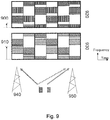
- Fig. 9 illustrates inter-cell interference coordination with synchronised cyclic frequency hopping and different initial offset in neighbouring cells.
- the initial offset for cell 1 920 is depicted as 900, while the initial offset 910 for cell 2 930 is depicted with 910.
- the first user is located at the edge of cell 1 920 and depicted by the grid-lined areas in cell 1 920, while the second user is located at the edge of cell 2 930 depicted by the shadowed areas in cell 2 930.
- Uplink control resources for each user in each of the cells 920, 930 are represented by the brick-shaped areas.
- Cell edge users are placed at the same relative frequency position in each cell to avoid collision. Furthermore, path gain measurements in neighboring cells which a user terminal any way needs to perform for hand over reasons, can be used to provide good predictions on the level of caused interference in neighboring cells. Since the frequency hopping effectively provides diversity over the fast fading, we can approximate the interference caused by the users that are scheduled in one cell as the transmitted power level times the path gain to the corresponding interfered cell. This information may be used in the scheduling decision as well, e.g. we might want to assure that the interference that we cause on resources used for control signaling in a neighboring cell is below a threshold.
- the curve with the reference number 1040 is the one that wraps around the frequency edge, since it is cyclically frequency-shifted by 62 sub-carriers.
- Fig. 10 shows a curve 1020 that is the IFFT-transformed curve without cyclic frequency shift (note that the original data samples are interpolated by a sinc-like (sin( x )/ x ) function) and another curve 1030 which is shifted in frequency by 8 sub-carriers.
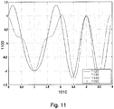
- Fig. 11 we see a simple example of cyclic frequency shifts when the number of used symbols is less then the number of IFFT-inputs, i.e. when N used ⁇ N ifft .
- the curves represent the IFFT outputs, where their amplitude 1100 is shown as a function of time 1110.
- N first 2
- N last 2
- N IFFT-inputs 64.
- the curve depicted with the reference number 1140 wraps around the frequency edge and is cyclically frequency-shifted by 58 sub-carriers.
- Curves with the reference numbers 1120 and 1130 represent the IFFT-transformed signals which are cyclically shifted by 0 and 8 sub-carriers respectively.
- the curve 1140 that is cyclically wrapped around the edge of the N used data sub-carriers has somewhat larger envelope variations than the non wrapped curves (the curves with the reference numbers 1120 and 1130). The reason is that the curve 1140 is actually oversampled and frequency translated two times while the non wrapped curves could be seen as having only a single over-sampling and frequency translation step.
- the first over-sampling and frequency translation takes place when expanding from N data to N used samples in step 510, 520, and 530 of Figure 5 .
- the second over-sampling and frequency translation step takes place in the IFFT 540 where the signal is expanded from N used to N ifft samples and an additional frequency shift is introduced by the N first zeros inserted before the first used data sub-carrier.
- Figure 12 we show an example of the envelope distribution when using QPSK modulation.
- the probability 1200 that the absolute amplitude of the resulting cyclically wrapped (CW) DFT-S-OFDM signal is larger than a value 1210.
- the average power of the CW-DFT-S-OFDM signal is normalized to one.
- the original data samples are taken from random QPSK-modulated data and statistics were collected over 10000 CW-DFT-S-OFDM symbols.
- the curve 1230 where a cyclic frequency shift of 280 sub-carriers is performed shows somewhat larger envelope variations than the curve 1240 which is not wrapped around the N used frequency edge (the cyclic shift 0 was used for 1240).
- the dashed black curve 1250 shows the envelope distribution of OFDM with the same parameters. We see that the envelope variations of CW-DFT-S-OFDM is significantly lower than that of OFDM.
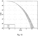
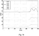
- Figs. 13 and 14 it is examined how the envelope distribution varies with the size of the cyclic shift.
- the graphs shown are the IFFT-transformed signals, where the probability 1300 that the absolute amplitude of the CW-DFT-S-OFDM modulated signal is larger than a value 1310.
- the curve 1320 in light grey in Figure 13 represents frequency shifts that are less than or equal to N used - N data , i.e. the cases when no cyclic frequency wrapping occurs.
- the black curves 1330 represent the cases when frequency wrapping occurs. We see that there is a small penalty in terms of an envelope variation increase when we wrap around the frequency.
- Fig. 14 it is demonstrated how the envelope variation varies with the size of the cyclic frequency shift.
- the curves listed from top to bottom in the box in Fig. 14 show the signal envelope of the CW-DFT-S-OFDM modulated signal at different probabilities, i.e. from 10 -1 1420 down to 10 -6 1470.
- the values in Figure 14 can be directly compared to the values shown in Figure 12 .
- the method steps described in Fig. 5 and the frequency hopping explained earlier and illustrated in Figs. 7 and 8 may be implemented by a computer program executed inside the terminal device 400 in Fig. 4 .
- the computer program may also be stored in a memory (not shown) of the terminal device 400 or executed on an ASIC (Application Specific Integrated Circuit).
Description
- The present application is related to a modification of a transmission scheme proposed for 3G LTE (Long Term Evolution) known as DFT-S-OFDMA (Discrete Fourier Transform Spread Orthogonal Frequency Division Multiple Access).
- 3rd Generation Partnership Project; Technical Specification Group Radio Access Network; Physical layer aspects for evolved Universal Terrestrial Radio Access (UTRA) (Release 7), 3GPP STANDARD; 3GPP TR 25.814, 3RD GENERATION PARTNERSHIP PROJECT (3GPP), no. V7.0.0, 1 June 200, pages 1-126, describes single-carrier transmission (SC-FDMA) with cyclic prefix to achieve uplink inter-user orthogonality and to enable efficient frequency-domain equalization at the receiver side. Frequency-domain generation of the signal, sometimes known as DFT -spread OFDM, is used.
- In the standardization of 3GPP (Third Generation Partnership Project) LTE (Long Term Evolution) an orthogonal single carrier transmission scheme with frequency multiplexing of users is selected for the uplink. The uplink transmission scheme proposed for LTE is known as DFT-S-OFDMA and the basic principle is depicted in
Fig. 1 . - At
step 100, a size N DFT (Discrete Fourier Transform) is first applied to a block of N modulation symbols N data. This transforms the modulation symbols to the frequency domain. Next, at steps 110-120, spectrum shaping of the thus transformed symbols N data is applied in the frequency domain. The first step at 110 involves the bandwidth expansion of the DFT-transformed modulation symbols through block repetition into a larger number of symbols N used, while the second step comprises the filtering of the expanded symbols in the frequency domain. - After spectrum shaping, mapping is done to the IFFT (Inverse Fast Fourier Transform) inputs N used at
step 130. This mapping can be performed in several different ways. Two different mappings, often referred to as localized and distributed mappings, have been proposed for LTE. In case of localized mapping, the mapping is done to consecutive IFFT inputs and in case of distributed mapping the mapping is done to equally spaced IFFT inputs. Thereafter, atstep 140 the mapped modulation symbols N ifft are IFFT-transformed forming a sequential data stream. Finally, atstep 150, a so called CP (Cyclic Prefix) is attached to the sequential data stream in order to avoid ISI (Inter Symbol Interference) and ICI (Inter Carrier Interference) at the receiver. The transmitted signal is a low-PAR (Peak-to-Average Power Ratio) "single-carrier" signal despite the apparent "multi-carrier" structure - see alsoUS2003123383 from UNIQUE BROADBAND SYSTEMS INC [CA], published on 03/07/20103. The difference between the traditional OFDMA-structure commonly used in wireless communication networks and DFT-S-OFDMA is that in traditional OFDMA the data symbols are directly mapped onto an arbitrary set of sub-carriers while in DFT-S-OFDMA the data symbols are first transformed by a DFT and then mapped to either a consecutive or an equally spaced set of sub-carriers. - In case of localized mapping however, the mapping onto consecutive sub-carriers in DFT-S-OFDMA leads to several problems. If radio resources for a user in such a wireless communication network are scheduled in the middle of the frequency band then the remaining transmission resource becomes fragmented into two parts. The next user to be scheduled resources may then only use the scheduled resources in one of the remaining fragments as a consequence of the single carrier restriction. This limits the achievable bit rate of that user.
- Another area which may result in uplink single carrier frequency fragmentation is the application of DFT-S-OFDMA to frequency hopping. Even if consecutive frequency allocations may be allocated to different UEs in one time interval problems will arise when users hop around in frequency. This becomes a significant problem in case all users are assigned frequency allocations of different sizes.
- Also, when it comes to inter cell interference coordination solutions for the uplink resource fragmentation may become a problem. If, for example, it is desired to make it possible for cell edge users in different cells to communicate on orthogonal uplink resources, then a situation may arise where the cell edge user may be allocated transmission resources in the middle of the frequency band which will lead to a fragmented resource in that cell.
- It is an object of the current invention to resolve the shortcomings of the currently proposed LTE single carrier solution.
- The invention is presented in the claims. The embodiments which do not fall within the scope of the claims are to be interpreted as examples. The object of the invention is achieved by a transmitter device for a wireless communication network comprising a transform unit for transforming a signal from the time domain to the frequency domain, an expansion unit for expanding the transformed signal in the frequency domain and an inverse transform unit for performing the transformation of the expanded signal in the frequency domain back into the time domain where the transmitter further comprises a cyclic shifting unit adapted to perform a cyclic frequency shift for the frequency domain signal over at least part of the available bandwidth for the frequencies used
- The advantage of this solution is the ability to allocate a user to an available bandwidth without fragmenting it and therefore making it possible for other users to be allocated to the remaining part of the bandwidth.
- According to another variant of the present invention the object of the invention is achieved by a transmitter device for a wireless communication network comprising a transmitter device for a wireless communication network comprising a first expansion unit for upconverting an input signal in the time domain, a first convolution unit adapted for cyclically convoluting the upconverted input signal with a first interpolation filter and a first multiplication unit for phase rotating the upconverted and cyclically convoluted input signal producing an output signal, where the transmitter further comprises a second expansion unit for upconverting the output signal in the time domain, a second interpolation unit for cyclically convoluting the output signal with a second interpolation filter and a second multiplication unit for phase rotating the upconverted and cyclically convoluted output signal.
- The advantage of this variant is the ability to implement the present invention in the time domain as well.
- According to yet another aspect of the present invention the object of the invention is achieved by method for signal processing in a wireless communication network comprising the steps:
- a) performing discrete transformation on a signal from the time domain to the frequency domain;
- c) expanding the frequency transformed signal in the frequency domain;
- d) cyclically shifting the frequency transformed signal around at least part of the available bandwidth
- e) transforming the thus frequency shifted signal from the frequency domain back to the time domain.
- According to another variant of the present invention the object of the invention is achieved by a method for signal processing in a wireless communication network comprising the steps:
- a) upsampling an input signal in the time domain;
- b) cyclically convoluting the upsampled input signal by multiplying it with a first interpolation filter;
- c) phase rotating the cyclically convoluted input signal producing an output signal;
- d) upsampling the output signal in the time domain;
- e) cyclically convoluting the upsampled output signal by multiplying it with a second interpolation filter;
- f) phase rotating the cyclically convoluted output signal.
- Thus, the method according to the present invention may be performed both in the frequency and time domains.
- Moreover, another aspect of the present invention is related to a computer program for signal processing in a wireless communication network comprising instruction sets for:
- a) performing discrete transformation on a signal from the time domain to the frequency domain;
- c) expanding the frequency transformed signal in the frequency domain;
- d) cyclically shifting the frequency transformed signal around at least part of the available bandwidth and;
- e) transforming the thus frequency shifted signal from the frequency domain back to the time domain.
- According to yet another variant of the present invention the present invention is related to a computer program comprising instruction sets for:
- a) upsampling an input signal in the time domain;
- b) cyclically convoluting the upsampled input signal by multiplying it with a first interpolation filter;
- c) phase rotating the cyclically convoluted input signal producing an output signal;
- d) upsampling the output signal in the time domain;
- e) cyclically convoluting the upsampled output signal by multiplying it with a second interpolation filter;
- f) phase rotating the cyclically convoluted output signal.
- The invention will be more readily understood with the help of the detailed description and the accompanying drawings.
-
-
Fig. 1 illustrates a known contemplated DFT-S-OFDMA (Discrete Fourier Transform Spread Orthogonal Frequency Multiple Access) scheme according to the 3G LTE uplink. -
Fig. 2 illustrates the basic principle underlying the present invention. -
Fig. 3 illustrates the basic principle fromFig. 2 in more detail. -
Fig. 4 illustrates a transmitter device according to the present invention. -
Fig. 5 represents a block diagram of a transmitter implementing one embodiment of the present invention. -
Fig. 6 is a schematic representation of two transmitters with filters covering different amounts of the available bandwidth. -
Fig. 7 illustrates fragmentation loss in a wireless communication network. -
Fig. 8 illustrates a second embodiment of the present invention. -
Fig. 9 illustrates the second embodiment of the present invention fromFig. 7 applied to overlapping cells. -
Fig. 10 represents simulation results of the method according to a first embodiment of the present invention. -
Fig. 11 represents simulation results of the method according to a second embodiment of the present invention. -
Fig. 12 represents simulation results of the method according to a third embodiment of the present invention. -
Fig. 13 represents simulation results of the method according to a fourth embodiment of the present invention. -
Fig. 14 represents simulation results of method according to a fourth embodiment of the present invention in more detail. -
Fig. 2 illustrates the cyclic wraparound of a DFT spread OFDMA signal according to one embodiment of the present invention. - The block consisting of filled and empty vertical bars represents the available bandwidth expressed as the available frequency spectrum, whereas the filled and empty vertical bars represent allocated and unallocated sub-carrier frequencies, respectively.
- A user depicted may for example be allocated sub-carrier frequencies at the beginning of the frequency spectrum shown by the filled
vertical bars 200 in the uppermost block. - Also, the N data sub-carrier frequencies allocated to the user may be shifted upwards in the available frequency spectrum as shown by the filled
vertical bars - Finally, using the periodical and symmetrical nature of the DFT, a user may be allocated subcarrier frequencies at the edges of the available frequency spectrum, by performing a so called frequency domain cyclic wrap-around as illustrated by the filled
bars 230 and the arrow pointing towards the left edge of the available frequency spectrum. - Event though the cyclic wrap-around over the whole bandwidth may be theoretically possible, it is for practical reasons performed over only a part of the available bandwidth.
- One reason for this is that oversampling in the IFFT greatly simplifies the steps of converting the signal from the digital to the analogue domain by means of a digital-to-analogue converter. For this reason it is beneficial to use an IFFT containing more samples than the number of sub-carriers used for transmitting data. The resulting oversampling performed by the IFFT relaxes the requirements that are put on the reconstruction filters used inside of the digital-to-analog conversion unit. Furthermore, it is also common to perform some additional filtering in the digital and/or analogue domains e.g. to ensure that the resulting signal fits inside a certain spectrum mask. Since side lobes from both the low end part and the high end part of the spectrum need to be filtered out it is not sufficient to just perform oversampling in the IFFT by inserting a number of zeros (N last) after the last used sub-carriers but also a number of zeros (N first) is typically inserted before the first used sub-carrier. Finally, in the up-conversion from an analogue base band signal to a signal on the desired radio frequency some interfering component of the carrier frequency component may leak into sub-carrier number zero (i.e. the DC sub-carrier) which might make that sub-carrier unusable for data communication. Similar problems exists also in the receiver when performing the corresponding steps of downconverting the received signal from radio frequency to base band, base band receiver filtering, and analogue-to-digital conversion.
- For the abovementioned reasons it will be difficult to span the data signal over the whole available bandwidth. In other words, the IFFT contains more inputs than the number of used sub-carriers.
- Another reason to perform cyclic frequency shift over a part of the bandwidth spanned by the IFFT is that for the LTE uplink the control channels (physical uplink control channel or PUCCH in 3GPP terminology) are located at the high and low end edges of the uplink transmission band. The shared data channel (physical uplink shared channel or PUSCH) is located in the remaining middle part of the spectrum. In order to avoid resource fragmentation when a first user is allocated resources in the middle of the PUSCH band a second user may be allocated all the remaining resources if it is capable of performing cyclic frequency shift over the remaining PUSCH resources. Thus all remaining resources can be allocated the second user and overlap with control channels can be avoided.
- Yet another reason to perform cyclic frequency shift over a part of the bandwidth spanned by the IFFT is that it enables frequency dependent scheduling that aims at exploiting the multi-path fading variations of the radio channel also for users with large frequency allocations. In case a user is allocated a small bandwidth then a scheduler can place that user on consecutive resources in the frequency domain where the instantaneous channel conditions are favourable. However, in case the bandwidth of a user is significantly larger than the coherence bandwidth of the channel, any consecutive cannel allocation will consist of both good quality resources and bad quality resources. With cyclic wrapping over a partial bandwidth it is possible to allocate one user to two continuous sets of resources that both have favourable radio conditions but are not adjacent in frequency. The data symbols are then cyclically mapped to the frequency resources in accordance with the enclosed invention. In this embodiment the "used part" of the bandwidth over which the cyclic frequency shifting is performed corresponds to the total bandwidth used by one single user. Other users that are simultaneously scheduled may perform cyclic frequency shifts over some other bandwidths.
- Therefore, in contrast to
Fig. 2, Fig. 3 illustrates the cyclic frequency shift over a partial bandwidth. Here, the total number ofsymbols 300 which may be inserted into the IFFT is divided into a first number of zero valuedsymbols 310, a number of symbols over which resource allocations to different users may be cyclically shifted 330, and a second number of zero valuedsymbols 350. The cyclically shifted resource allocation corresponding to one user may now consist of afirst part 340 at the high end of the usedIFFT input symbols 330 and asecond part 320 at the low end of the usedIFFT input symbols 330. The zero valuedsymbols Fig. 3 is performed over the used part of theIFFT 330. Even though the resulting mapping after the cyclic frequency shift is not performed over a contiguous set of sub-carriers this in fact results in a signal that still has single-carrier properties. This will be explained in more detail later in the text. -
Fig. 4 illustrates atransmitter device 400 according to one embodiment of the present invention. It should be pointed out that thetransmitter device 400 may comprise a base station transceiver, but also a user terminal. - In this example, the
transmitter device 400 comprises a receiver/transmitter combination 410 for communication in a wireless communication network. One function of the receiver/transmitter combination 410 may be to receive reports on channel quality from user terminals in the wireless communication network, such as so called CQI-reports (Channel Quality Indicator reports). Based on these reports, thetransmitter device 400 may then allocate the appropriate amount of bandwidth for each user terminal. This is valid for the scenario where thetransmitter device 400 is a base station transceiver. - Furthermore, the
transmitter device 400 also comprises adiscrete transformation unit 420 responsible for performing transformation of an input signal from the time domain into the frequency domain by, for example, performing DFT (Discrete Fourier Transform) on the incoming signal. Of course, other types of transforms may be performed on the incoming signal, such as FFT, discrete cosine transform and others as long as they are cyclic in nature. The main point here is to transform the signal into the frequency domain using a cyclic discrete transform. - Moreover, the
transmitter device 400 also comprises anexpansion unit 430, for expanding the frequency transformed signal in the frequency domain. Expansion may be achieved by block repetition or by other means. - The
transmitter device 440 also comprises afrequency shift unit 440 whose task it is to perform a cyclic frequency shift of the expanded and frequency transformed signal. This is simply a frequency shift of a frequency transformed and expanded signal using the cyclic property of the discrete frequency transform where some of the shifted subcarrier frequencies will appear on the left edge of the spectrum as first, second, third carrier frequencies and so on. The number of the carrier frequencies that will reappear on the left edge is simply dependent of the size of the frequency shift. The advantage of the cyclic wraparound performed byunit 440 is that a user terminal may be allocated one portion of the available bandwidth without fragmenting it. Thus, it may be possible to allocate other user terminals to the remaining part of the available bandwidth. This was not possible with known technology where a user terminal having been allocated to the middle of the available bandwidth lead to a bandwidth fragmentation which made it difficulty for other user terminals to use the remaining bandwidth. - The
frequency shift unit 440 may also be adapted to oversample the frequency transformed signal by inserting a number of zeroes before and after the first and second used carrier frequencies for example according to the scheme depicted inFig. 3 . In this fashion, the frequency transformed signal will be easier to convert from the digital to the analog domain for the reasons elaborated in the description inFig. 3 earlier. - Also, the
transmitter device 400 additionally comprises atime transform unit 450 adapted for transforming the frequency shifted signal with cyclic wraparound back into the time domain. Usually, thetransmitter device 400 will be adapted to perform a time transformation of the frequency shifted signal which uses the transform inverse to the frequency transform performed by the discretefrequency transformation unit 420. - Optionally, the transmitter device may comprise a
frequency synchronisation unit 460 responsible for performing tasks such as frequency hopping for the above frequency signal processed by thefrequency shift unit 440. Thefrequency synchronisation unit 460 may here be adapted for synchronising the cyclic frequency wraparound with other frequency synchronisation units in other transmitter devices. These frequencies used in the various transmitter devices may be either preconfigured (in which case thefrequency synchronisation unit 460 would not be necessary) or communicated to other transmitter devices by thefrequency synchronisation unit 460 via the transmitter/receiver combination 410. In this fashion, the risk of two transmitter devices using the same frequency spectrum at the same time and thus causing interference may be reduced. - It may be appreciated here that the units of the
transmitter device 400 which in the example above are adapted for performing the above signal operations in the frequency domain may also be adapted for performing equivalent operations in the time domain. - In such a case, the
transformation unit 420 may perform signal transformation from the time into the frequency domain or vice versa, while theinverse transformation unit 450 may perform the identical operation but as an inverse transform operation. However, for the time domain implementation the transformation andinverse transformation units 450 may not bee needed if the signal already is in the time domain. - The expansion and shifting
units synchronisation unit 460 may additionally perform time synchronisation as the equivalent to frequency synchronisation in the frequency domain. -
Fig. 5 depicts a block diagram depicting the method steps performed by the transmitter fromFig. 4 according to one embodiment of the present invention. - A number of data symbols N data is transformed into the frequency domain at
step 500 by using a DFT-transform. Atstep 510, the DFT-transformed N data symbols are expanded in bandwidth by for example using block repetition. Hence, the number of symbols is increased from the original N data number of symbols to the N used number of symbols. Thereafter, atstep 520, frequency domain filtering is performed on the now expanded N used symbols. So far, the steps performed are identical to those of the proposed DFT-S-OFDM method. - However, at
step 530, a cyclic frequency shift is performed on the filtered N used number of data symbols thus avoiding fragmentation of the remaining available bandwidth. - Next, at
step 540, the N first and N last number of zeroes are inserted before and after the first and second used carrier frequencies and an IFFT transformation operation is performed on the N ifft number of data symbols. Note that in theory both N first and N last may be equal to zero but for practical implementation reasons the preferred embodiment of this invention is the case when both N first and N last are larger than zero. - Finally, after the thus cyclically shifted and zero-filled sub-carriers are consecutively mapped into the IFFT a sequential bitstream is created, whereafter at step 550 a CP is appended to the sequential bitstream.
- Note that not all UEs (User Equipments) may be able to perform frequency domain wrap around. One obvious requirement is that the UE has a transmitter filter that covers the whole available bandwidth. In the example shown in
Fig. 6 auser 600 with a transmission filter that covers the whole bandwidth and twousers - It may be appreciated that the operations performed in
Fig. 5 may equally be performed by equivalent operations in the time domain, since, for example, an operation in the frequency domain always has an equivalent in the time domain and vice versa. Thus, for example an operation in the time domain equivalent to bandwidth expansion performed instep 510 inFig. 5 would be upsampling of data symbols in the time domain. This would have to be performed twice in the time domain. Frequency filtering atstep 520 may be equalled by a corresponding filtering in the time domain. Likewise, the cyclic frequency shift performed atstep 530 inFig. 5 may be equalled by a corresponding cyclical convolution with an interpolation filter and subsequent phase rotation by means of multiplication by a phasor vector at a first stage plus a cyclical convolution and phase rotation at a second stage. -
Fig. 7 depicts a comparison between a full-bandwidthcapable UE 700 versus two half-bandwidthcapable UEs 710, 720 over two frames represented as the width of theblocks - The part of the available bandwidth depicted with reference number 730 represents the control resources needed for uplink control signalling for users that were not scheduled to transmit data in this frame.
- In the left-most figure 740, a full bandwidth capable UE may fill the remaining resource if there is an allocation in the middle of the frequency band e.g. for uplink control signalling from non scheduled UEs.
- In contrast, we see in the right-most figure 750 a case where the scheduled
users 710, 720 are not capable of transmitting over the whole system bandwidth. In thiscase fragmentation loss 760 will occur in case theuser 720 has more data to send and enough available transmit power to be able to utilize a larger resource allocation. - Uplink frequency hopping may be realized by simply changing which of the Nursed sub-carriers that we index as number zero. This is shown as an example in
Fig. 8 , where the grey bars represent the uplink control resource 800. Furthermore, the sub-carrier zero reference index insubframes reference number 810, while its position insubframes reference numbers Reference number 840 represents the length of one sub-frame, whilereference number 850 and 860 represent the length of one TTI (Transmission Time Interval) and one hopping pattern period, respectively. - It is assumed that both uplink control resources 800 and scheduled resources (not shown) hop around in frequency. It is further assumed in this example that the uplink control resources for ACK/NACK/CQI (Acknowledged/Not Acknolwedged/Channel Quality Indicator) signaling for UEs that do not have uplink data start at the
relative index 0. These control resources 800 are schematically drawn as a brick-shaped pattern , while the resources available for scheduled data are displayed in white.
However, it may be equally possible to let the control resources 800 be locked to certain frequencies and to perform frequency hopping on the scheduled resources only. - Frequency hopping is a simple and efficient way of handling inter-cell interference. By selecting different hopping patterns in neighboring cells one may achieve a randomization of the inter-cell interference. The hopping patterns may be orthogonal, in which case they essentially never overlap, or they may be pseudo-random with low probability of overlapping.
- However, the current invention also allows for some more advanced inter-cell interference co-ordination (ICIC) schemes. For example, the same frequency hopping pattern may be used in neighboring cells and different frequency offsets may be selected for each interfering cell. By hopping in a synchronized fashion it is ensured that the interference on one relative sub-carrier becomes predictable over the whole hopping pattern period. Hence the link adaptation and scheduling may adapt to the current interference situation.
- This is especially attractive in a scheduled uplink scenario, since then it is expensive to obtain channel quality knowledge for all users. Typically, in order to support channel dependent scheduling each user would be required to send periodic sounding signals over the whole bandwidth so that the base station could estimate the channel quality over the full bandwidth for each user. This knowledge could be used by the base station in order to perform channel dependent scheduling and link adaptation. However, since users must be allocated to cyclically continuous sub-carriers it is difficult to obtain any multi user diversity gain without having a large number of users with small resource allocations. And since a large number of users results in a large number of uplink channel sounding transmission consuming a large portion of the uplink capacity, it is unlikely that there will be any real gain left.
- However, if we are using frequency hopping on the uplink then the link adaptation does not have to follow the fast fading and it can instead adjust to the slowly varying path gain and the different inter-cell interference that are received on the different sub-carriers. The inter-cell interference can be estimated by the base station without any channel sounding signals from the UEs and the slowly varying path gain on the uplink can e.g. be approximated as being equal to the path gain on the downlink. Thus with synchronized cyclic frequency hopping it is possible to perform scheduling a link adaptation based on the frequency dependent inter-cell interference.
- In the uplink it is the users at the cell edge that cause the most interference in the neighboring cells. They are also often power limited and can therefore often not make use of the full bandwidth. Hence it is possible to start allocating resources to cell edge users from the relative resource index zero in each cell. And if the relative index zero is different in interfering cells it is assured that the cell edge users do not collide with each other on the same resource. This is schematically depicted in
Figure 8 below. -
Fig. 9 illustrates inter-cell interference coordination with synchronised cyclic frequency hopping and different initial offset in neighbouring cells. - The initial offset for
cell 1 920 is depicted as 900, while the initial offset 910 forcell 2 930 is depicted with 910. The first user is located at the edge ofcell 1 920 and depicted by the grid-lined areas incell 1 920, while the second user is located at the edge ofcell 2 930 depicted by the shadowed areas incell 2 930. - Since both users are located at the edges of
cell 1 and cell 2 (920, 930) interferences from the first and second users are likely to occur. Therefore, the interference from the second user incell 1 920 is depicted by the gray-barred areas, whereas interference from the second user incell 2 930 is depicted by the knitted areas incell 2 930. - Uplink control resources for each user in each of the
cells - In
Figure 9 we see that the interference from the second user marked with shadowed lines incell 2 930 stays at the same relative position incell 1 920 over the hopping period. Note that it is the cyclic frequency wrapping that enables this. - Cell edge users are placed at the same relative frequency position in each cell to avoid collision. Furthermore, path gain measurements in neighboring cells which a user terminal any way needs to perform for hand over reasons, can be used to provide good predictions on the level of caused interference in neighboring cells. Since the frequency hopping effectively provides diversity over the fast fading, we can approximate the interference caused by the users that are scheduled in one cell as the transmitted power level times the path gain to the corresponding interfered cell. This information may be used in the scheduling decision as well, e.g. we might want to assure that the interference that we cause on resources used for control signaling in a neighboring cell is below a threshold.
- In
Fig. 10 we see a simple example of cyclic frequency shifts when the number of used symbols is equal to the number of IFFT-inputs, i.e. when N ursed = N ifft. The graph inFig. 10 shows the output from the IFFT-transformation as anamplitude 1000 versustime 1010 diagram, where four input data symbols (N data = 4) 1050 are oversampled into 64 data symbols N used = 64) which are IFFT-transformed into the time domain. The original data points sampled are X = [1 -1 1 1] represented by the reference number 1050. Moreover, the curve with the reference number 1040 is the one that wraps around the frequency edge, since it is cyclically frequency-shifted by 62 sub-carriers. AlsoFig. 10 shows acurve 1020 that is the IFFT-transformed curve without cyclic frequency shift (note that the original data samples are interpolated by a sinc-like (sin(x)/x) function) and another curve 1030 which is shifted in frequency by 8 sub-carriers. - In
Fig. 11 we see a simple example of cyclic frequency shifts when the number of used symbols is less then the number of IFFT-inputs, i.e. when Nused < Nifft. As in the previous example inFig. 10 , the curves represent the IFFT outputs, where theiramplitude 1100 is shown as a function of time 1110. In the example illustrated, theoriginal data samples 1150 are identical to the ones in the example inFig. 9 , i.e. X = [1 -1 1 1], which means that the number of data samples is N data= 4, whereas the number of used sub-carrier symbols is N data = 60. Moreover, the number of zeroes inputted before the first used sub-carrier (not shown) is N first = 2, while the number of zeroes inputted after the second used sub-carrier is also N last = 2. Also, the number of IFFT-inputs was N ifft = 64. - In this example, the curve depicted with the
reference number 1140 wraps around the frequency edge and is cyclically frequency-shifted by 58 sub-carriers. We note that we still have a signal that is equal to the data points [1 -1 1 1] in the sampling instances. Curves with thereference numbers curve 1120 is actually frequency translated by two sub-carriers by the insertion of the N first = 2 zero valued samples before the first used data sub-carrier. It appears that thecurve 1140 that is cyclically wrapped around the edge of the N used data sub-carriers has somewhat larger envelope variations than the non wrapped curves (the curves with thereference numbers 1120 and 1130). The reason is that thecurve 1140 is actually oversampled and frequency translated two times while the non wrapped curves could be seen as having only a single over-sampling and frequency translation step. The first over-sampling and frequency translation takes place when expanding from N data to N used samples instep Figure 5 . The second over-sampling and frequency translation step takes place in theIFFT 540 where the signal is expanded from N used to N ifft samples and an additional frequency shift is introduced by the N first zeros inserted before the first used data sub-carrier. However in the case when there is no frequency wrapping (i.e. for thecurves 1120 and 1130) these two consecutive over-sampling and frequency translation steps can be combined into one single over-sampling and frequency translation step. Since every over-sampling step introduces some envelope variations due to the sinc-like shape of the resulting interpolation function we get slightly larger envelope variations for the cyclically frequency wrappedcurve 1140. This effect is further examined inFigures 12 and13 . - In
Figure 12 we show an example of the envelope distribution when using QPSK modulation. Here, we see theprobability 1200 that the absolute amplitude of the resulting cyclically wrapped (CW) DFT-S-OFDM signal is larger than avalue 1210. InFig. 12 the average power of the CW-DFT-S-OFDM signal is normalized to one. The number of data samples this time was N data = 72 which corresponds to the case when 6 resource blocks each consisting of 12 sub-carriers each are used (the size of a resource-block is in line with the current numerology assumed for the LTE uplink in 3GPP). Moreover, the number of usable sub-carriers, N used equals 300 and the IFFT size is Nifft = 512, and N first = N last = 106. The original data samples are taken from random QPSK-modulated data and statistics were collected over 10000 CW-DFT-S-OFDM symbols. It can be seen that thecurve 1230 where a cyclic frequency shift of 280 sub-carriers is performed shows somewhat larger envelope variations than thecurve 1240 which is not wrapped around the N used frequency edge (thecyclic shift 0 was used for 1240). As a reference, the dashedblack curve 1250 shows the envelope distribution of OFDM with the same parameters. We see that the envelope variations of CW-DFT-S-OFDM is significantly lower than that of OFDM. - In
Figs. 13 and14 it is examined how the envelope distribution varies with the size of the cyclic shift. In these figures, the number of original data symbols was N data = 12 x 6 = 48, while the number of used data symbols was N used = 300. The number of inserted zeroes before the first used sub-carriers was N first = 106 and after the second used sub-carriers N last = 106. The number of IFFT-inputs was N ifft = 512 where the original data sampled was QPSK-modulated and where statistics had been collected over 10000 symbols. Analogously to the curves inFig. 12 , the graphs shown are the IFFT-transformed signals, where theprobability 1300 that the absolute amplitude of the CW-DFT-S-OFDM modulated signal is larger than avalue 1310. - The
curve 1320 in light grey inFigure 13 represents frequency shifts that are less than or equal to N used - N data, i.e. the cases when no cyclic frequency wrapping occurs. The black curves 1330 represent the cases when frequency wrapping occurs. We see that there is a small penalty in terms of an envelope variation increase when we wrap around the frequency. - In
Fig. 14 it is demonstrated how the envelope variation varies with the size of the cyclic frequency shift. The curves listed from top to bottom in the box inFig. 14 show the signal envelope of the CW-DFT-S-OFDM modulated signal at different probabilities, i.e. from 10-1 1420 down to 10-6 1470. The values inFigure 14 can be directly compared to the values shown inFigure 12 . - As a final remark, it may be mentioned that the method steps described in
Fig. 5 and the frequency hopping explained earlier and illustrated inFigs. 7 and8 may be implemented by a computer program executed inside theterminal device 400 inFig. 4 . However, the computer program may also be stored in a memory (not shown) of theterminal device 400 or executed on an ASIC (Application Specific Integrated Circuit). - A skilled person having read the above disclosure may quite possibly contemplate other embodiments of the present invention. Ultimately, the scope of the present invention is only limited by the accompanying claims.
Claims (9)
- A Discrete Fourier Transform Spread Orthogonal Frequency Multiple Access, DFT-S-OFDMA transmitter device (400) for a wireless communication network comprising a transform unit (420) using a transform with cyclic properties for transforming a signal from the time domain to the frequency domain, an expansion unit (430) for expanding the transformed signal in the frequency domain and an inverse transform unit (450) for performing the transformation of the expanded signal in the frequency domain back into the time domain
characterised by
that said transmitter further comprises a shifting unit (440) adapted to perform, for uplink sub-carrier frequencies allocated to a user of the transmitter (400), a cyclic frequency shift of the expanded and frequency transformed signal upwards in at least part of the available bandwidth of the inverse transform unit (450) such that the cyclically shifted sub-carrier frequencies corresponding to the user now consist of a first part (340) at the high end of said available bandwidth (330) and a second part (320) at the low end of said available bandwidth (330). - Transmitter device according to claim 1, whereas said shifting unit (440) is further adapted to perform oversampling on the frequency-transformed signal.
- Transmitter device according to claim 2 where said shifting unit (440) is adapted to perform said oversampling by a inserting a number of empty carrier radio resources before a first number of used radio resources in the available bandwidth.
- Transmitter device according to claims 2 or 3, where said shifting unit (440) is adapted to perform said oversampling by a inserting a number of empty carrier radio resources after a second number of used radio resources in the available bandwidth.
- Transmitter device according to one of the claims 1-4, wherein said shifting unit (440) is further adapted for translating the first number and second number of radio resources in the frequency domain.
- Transmitter device according to one of the claims 1-5, wherein the transmitter device (400) further comprises a synchronisation unit (450) for transmitting information indicative of the beginning of the used radio resources and the translation of the first and second number of radio resources in the frequency domain.
- A base station, or an access point comprising a transmitter device according to one of the previous claims.
- Method for signal processing in a Discrete Fourier Transform Spread Orthogonal Frequency Multiple Access, DFT-S-OFDMA transmitter in a wireless communication network comprising the steps:a) performing discrete transformation on a signal of a user terminal from the time domain to the frequency domain using a transform with cyclic properties;b) expanding the frequency transformed signal in the frequency domain;c) for uplink sub-carrier frequencies allocated to a user of the transmitter, cyclically shifting the expanded transformed signal upwards in at least part of the available bandwidth of an inverse transform unit (450) such that the cyclically shifted sub-carrier frequencies corresponding to the user now consist of a first part (340) at the high end of said available bandwidth (330) and a second part (320) at the low end of said available bandwidth (330), andd) transforming the thus frequency shifted signal from the frequency domain back to the time domain.
- Computer program for signal processing in a Discrete Fourier Transform Spread Orthogonal Frequency Multiple Access, DFT-S-OFDMA transmitter in a wireless communication network comprising instruction sets for:a) performing discrete transformation on a signal of a user terminal from the time domain to the frequency domain using a transform with cyclic properties;b) expanding the frequency transformed signal in the frequency domain;c) for uplink sub-carrier frequencies allocated to a user of the transmitter, cyclically shifting the expanded transformed signal upwards in at least part of the available bandwidth such that the cyclically shifted sub-carrier frequencies corresponding to the user now consist of a first part (340) at the high end of said available bandwidth (330) and a second part (320) at the low end of said available bandwidth (330), and;d) transforming the thus frequency shifted signal from the frequency domain back to the time domain.
Applications Claiming Priority (2)
| Application Number | Priority Date | Filing Date | Title |
|---|---|---|---|
| SE0602319 | 2006-11-02 | ||
| PCT/SE2007/050815 WO2008054322A2 (en) | 2006-11-02 | 2007-11-02 | Cyclically shifting a signal in frequency and time domain |
Publications (3)
| Publication Number | Publication Date |
|---|---|
| EP2078400A2 EP2078400A2 (en) | 2009-07-15 |
| EP2078400A4 EP2078400A4 (en) | 2014-05-21 |
| EP2078400B1 true EP2078400B1 (en) | 2017-09-27 |
Family
ID=39344728
Family Applications (1)
| Application Number | Title | Priority Date | Filing Date |
|---|---|---|---|
| EP07835399.2A Not-in-force EP2078400B1 (en) | 2006-11-02 | 2007-11-02 | Dft spread ofdm |
Country Status (6)
| Country | Link |
|---|---|
| US (1) | US7983145B2 (en) |
| EP (1) | EP2078400B1 (en) |
| JP (1) | JP5202535B2 (en) |
| CN (1) | CN101542997B (en) |
| CA (1) | CA2667187A1 (en) |
| WO (1) | WO2008054322A2 (en) |
Families Citing this family (25)
| Publication number | Priority date | Publication date | Assignee | Title |
|---|---|---|---|---|
| US7983145B2 (en) * | 2006-11-02 | 2011-07-19 | Telefonaktiebolaget Lm Ericsson (Publ) | DFT spread OFTM |
| WO2008115112A1 (en) * | 2007-03-22 | 2008-09-25 | Telefonaktiebolaget Lm Ericsson (Publ) | Method and arrangement in a telecommunication system |
| US20090180434A1 (en) * | 2008-01-16 | 2009-07-16 | Institute For Information Industry | Central control apparatus, signal transmission apparatus and signal forwarding apparatus for use in a multi-hop wireless network |
| EP2091194B1 (en) * | 2008-02-12 | 2014-06-25 | Telefonaktiebolaget L M Ericsson (PUBL) | Single carrier frequency division multiple access technique |
| KR101567078B1 (en) * | 2008-06-26 | 2015-11-09 | 엘지전자 주식회사 | Apparatus and method for data transmission using multiple antenna |
| KR101534349B1 (en) * | 2008-06-26 | 2015-07-10 | 엘지전자 주식회사 | Method for data transmission using space time block code |
| KR101467586B1 (en) | 2008-06-26 | 2014-12-02 | 엘지전자 주식회사 | Apparatus and method for data transmission using transmit diversity in wireless system |
| KR101507170B1 (en) * | 2008-06-26 | 2015-03-31 | 엘지전자 주식회사 | Apparatus and method for data transmission using transmit diversity in sc-fdma system |
| KR101497154B1 (en) * | 2008-06-26 | 2015-03-02 | 엘지전자 주식회사 | Apparatus and method for data transmission using transmit diversity in sc-fdma system |
| CN102106180A (en) * | 2008-08-07 | 2011-06-22 | 松下电器产业株式会社 | Frequency band allocation method and transmission device |
| CN101777940B (en) * | 2009-01-12 | 2013-08-14 | 华为技术有限公司 | Method, device and system for transmitting uplink information |
| CN102449921B (en) * | 2009-05-29 | 2014-06-11 | 松下电器产业株式会社 | Wireless communication apparatus and frequency hopping method |
| ES2555059T3 (en) * | 2009-06-16 | 2015-12-28 | Huawei Technologies Co., Ltd. | Mapping method for mapping a control channel, control channel detection method and corresponding device |
| CN101932140A (en) * | 2009-06-22 | 2010-12-29 | 华为技术有限公司 | Method and base station for adjusting radio frame sending time |
| US9271268B2 (en) * | 2010-01-08 | 2016-02-23 | Panasonic Intellectual Property Corporation Of America | Wireless transmission device, wireless reception device, and bandwidth allocation method for setting a band where other bands indicated by continuous band allocation information do not overlap |
| US8638868B2 (en) * | 2010-06-23 | 2014-01-28 | Telefonaktiebolaget L M Ericsson (Publ) | Methods and apparatus for varying reduced transmission resources |
| KR101761618B1 (en) * | 2010-06-25 | 2017-07-26 | 엘지전자 주식회사 | Apparatus and method of transmitting control information in wireless communication system |
| CN104094651B (en) * | 2011-12-02 | 2018-07-24 | 诺基亚通信公司 | The coordination frequency spectrum allocation and deallocation of frequency spectrum fragmentation is minimized in cognitive radio networks |
| WO2016127306A1 (en) * | 2015-02-10 | 2016-08-18 | 华为技术有限公司 | Data transmission method and transmitter |
| WO2018100591A1 (en) | 2016-12-02 | 2018-06-07 | Wisig Networks Private Limited | A method and a system for transmitting dft-s-ofdm symbols |
| TWI684334B (en) * | 2016-12-16 | 2020-02-01 | 大陸商貴州濎通芯物聯技術有限公司 | Cyclic-frequency shift orthogonal frequency division multiplex spread spectrum device |
| CN108235445B (en) | 2016-12-21 | 2021-03-09 | 大唐移动通信设备有限公司 | Method and device for detecting characteristic sequence in wireless communication system |
| KR20220108811A (en) * | 2019-12-13 | 2022-08-03 | 지티이 코포레이션 | Frequency-domain modulation scheme for low peak average power ratio |
| CN115086125B (en) * | 2022-08-11 | 2022-11-18 | 深圳市华普微电子有限公司 | Low-power consumption modulation method for micro frequency hopping multiple access communication system |
| WO2024047550A1 (en) * | 2022-08-31 | 2024-03-07 | Jio Platforms Limited | System and method for providing multiple bandwidth support using a frequency shifter |
Citations (1)
| Publication number | Priority date | Publication date | Assignee | Title |
|---|---|---|---|---|
| US20030123383A1 (en) * | 2001-06-11 | 2003-07-03 | Dmitri Korobkov | OFDM multiple sub-channel communication system |
Family Cites Families (10)
| Publication number | Priority date | Publication date | Assignee | Title |
|---|---|---|---|---|
| US6167102A (en) * | 1998-08-03 | 2000-12-26 | Telefonaktiebolaget Lm Ericsson (Publ) | System and method employing a reduced NCO lookup table |
| CN100553180C (en) * | 2004-03-31 | 2009-10-21 | 清华大学 | Tds-ofdm receiver adaptive channel estimation balancing method and system thereof |
| US7646703B2 (en) * | 2004-07-27 | 2010-01-12 | Broadcom Corporation | Backward-compatible long training sequences for wireless communication networks |
| CN1787507B (en) * | 2004-12-10 | 2010-04-28 | 清华大学 | Method for producing frame synchronizing in time domain synchronizing orthogonal frequency division multiplex system |
| US8406318B2 (en) * | 2006-02-13 | 2013-03-26 | Research In Motion Limited | System and method for ask OFDM transmission and reception |
| US7848446B2 (en) * | 2006-09-27 | 2010-12-07 | Telefonaktiebolaget L M Ericsson (Publ) | Reduction of peak-to-average-power ratio in a telecommunications system |
| US7983145B2 (en) * | 2006-11-02 | 2011-07-19 | Telefonaktiebolaget Lm Ericsson (Publ) | DFT spread OFTM |
| US20090040919A1 (en) * | 2007-08-09 | 2009-02-12 | Tarik Muharemovic | Transmission Using Nested OFDMA |
| US7746761B2 (en) * | 2007-10-25 | 2010-06-29 | Nokia Siemens Networks Oy | Techniques to generate constant envelope multicarrier transmission for wireless networks |
| US20100226448A1 (en) * | 2009-03-05 | 2010-09-09 | Paul Wilkinson Dent | Channel extrapolation from one frequency and time to another |
-
2007
- 2007-11-02 US US12/513,315 patent/US7983145B2/en active Active
- 2007-11-02 WO PCT/SE2007/050815 patent/WO2008054322A2/en active Application Filing
- 2007-11-02 CA CA002667187A patent/CA2667187A1/en not_active Abandoned
- 2007-11-02 JP JP2009535238A patent/JP5202535B2/en not_active Expired - Fee Related
- 2007-11-02 EP EP07835399.2A patent/EP2078400B1/en not_active Not-in-force
- 2007-11-02 CN CN2007800406297A patent/CN101542997B/en not_active Expired - Fee Related
Patent Citations (1)
| Publication number | Priority date | Publication date | Assignee | Title |
|---|---|---|---|---|
| US20030123383A1 (en) * | 2001-06-11 | 2003-07-03 | Dmitri Korobkov | OFDM multiple sub-channel communication system |
Also Published As
| Publication number | Publication date |
|---|---|
| EP2078400A4 (en) | 2014-05-21 |
| US7983145B2 (en) | 2011-07-19 |
| CN101542997A (en) | 2009-09-23 |
| JP5202535B2 (en) | 2013-06-05 |
| US20100111209A1 (en) | 2010-05-06 |
| CA2667187A1 (en) | 2008-05-08 |
| WO2008054322A3 (en) | 2008-06-26 |
| WO2008054322A2 (en) | 2008-05-08 |
| EP2078400A2 (en) | 2009-07-15 |
| CN101542997B (en) | 2012-08-08 |
| JP2010509801A (en) | 2010-03-25 |
Similar Documents
| Publication | Publication Date | Title |
|---|---|---|
| EP2078400B1 (en) | Dft spread ofdm | |
| US10312990B2 (en) | Signal sending or receiving method and device | |
| EP2183895B1 (en) | Transmission of data using repetition coding with PAPR reduction | |
| RU2436252C2 (en) | Method of transmitting control signals in wireless communication system | |
| US8811141B2 (en) | OFDM/OFDMA frame structure for communication systems | |
| US8126070B2 (en) | Method and base station for orthogonal frequency division multiplexing (OFDM) signal processing | |
| EP3289689B1 (en) | Method and system for low data rate transmission | |
| JP6631963B2 (en) | Generalized frequency division multiplex transmission for narrowband using Internet of Things (IoT) devices | |
| US10701685B2 (en) | Method and apparatus for asynchronous OFDMA/SC-FDMA | |
| IL203350A (en) | Multicarrier communication system employing explicit frequency hopping | |
| KR20090113385A (en) | Base station device, user device, and method used in mobile communication system | |
| US10785076B2 (en) | Method and apparatus for generating OFDM signals | |
| JP2009164754A (en) | Method of signal multiplexing and transmitting station in radio communication system | |
| EP3619883A1 (en) | Selection of waveform for uplink communications | |
| RU2737000C1 (en) | Access point, station, methods and computer programs | |
| EP2903198A1 (en) | Method and apparatus for exchanging information | |
| CN108737055A (en) | Method and apparatus for asynchronous OFDMA/SC-FDMA | |
| JP5027176B2 (en) | Radio base station apparatus, mobile terminal apparatus and radio access method | |
| CN111147215B (en) | Wireless communication method, device and system | |
| JP2016134854A (en) | Radio communication apparatus and radio communication system | |
| USRE47602E1 (en) | Method of transmitting data using repetition coding |
Legal Events
| Date | Code | Title | Description |
|---|---|---|---|
| PUAI | Public reference made under article 153(3) epc to a published international application that has entered the european phase |
Free format text: ORIGINAL CODE: 0009012 |
|
| 17P | Request for examination filed |
Effective date: 20090508 |
|
| AK | Designated contracting states |
Kind code of ref document: A2 Designated state(s): AT BE BG CH CY CZ DE DK EE ES FI FR GB GR HU IE IS IT LI LT LU LV MC MT NL PL PT RO SE SI SK TR |
|
| DAX | Request for extension of the european patent (deleted) | ||
| A4 | Supplementary search report drawn up and despatched |
Effective date: 20140422 |
|
| RIC1 | Information provided on ipc code assigned before grant |
Ipc: H04J 13/00 20110101ALI20140414BHEP Ipc: H04W 72/08 20090101ALI20140414BHEP Ipc: H04L 5/02 20060101ALI20140414BHEP Ipc: H04B 1/7143 20110101ALI20140414BHEP Ipc: H04L 27/26 20060101AFI20140414BHEP Ipc: H04B 1/715 20110101ALI20140414BHEP |
|
| GRAP | Despatch of communication of intention to grant a patent |
Free format text: ORIGINAL CODE: EPIDOSNIGR1 |
|
| STAA | Information on the status of an ep patent application or granted ep patent |
Free format text: STATUS: GRANT OF PATENT IS INTENDED |
|
| INTG | Intention to grant announced |
Effective date: 20170524 |
|
| GRAS | Grant fee paid |
Free format text: ORIGINAL CODE: EPIDOSNIGR3 |
|
| GRAA | (expected) grant |
Free format text: ORIGINAL CODE: 0009210 |
|
| STAA | Information on the status of an ep patent application or granted ep patent |
Free format text: STATUS: THE PATENT HAS BEEN GRANTED |
|
| AK | Designated contracting states |
Kind code of ref document: B1 Designated state(s): AT BE BG CH CY CZ DE DK EE ES FI FR GB GR HU IE IS IT LI LT LU LV MC MT NL PL PT RO SE SI SK TR |
|
| REG | Reference to a national code |
Ref country code: GB Ref legal event code: FG4D |
|
| REG | Reference to a national code |
Ref country code: CH Ref legal event code: EP |
|
| REG | Reference to a national code |
Ref country code: AT Ref legal event code: REF Ref document number: 932951 Country of ref document: AT Kind code of ref document: T Effective date: 20171015 |
|
| REG | Reference to a national code |
Ref country code: IE Ref legal event code: FG4D |
|
| REG | Reference to a national code |
Ref country code: DE Ref legal event code: R096 Ref document number: 602007052513 Country of ref document: DE |
|
| REG | Reference to a national code |
Ref country code: NL Ref legal event code: FP |
|
| PG25 | Lapsed in a contracting state [announced via postgrant information from national office to epo] |
Ref country code: SE Free format text: LAPSE BECAUSE OF FAILURE TO SUBMIT A TRANSLATION OF THE DESCRIPTION OR TO PAY THE FEE WITHIN THE PRESCRIBED TIME-LIMIT Effective date: 20170927 Ref country code: FI Free format text: LAPSE BECAUSE OF FAILURE TO SUBMIT A TRANSLATION OF THE DESCRIPTION OR TO PAY THE FEE WITHIN THE PRESCRIBED TIME-LIMIT Effective date: 20170927 Ref country code: LT Free format text: LAPSE BECAUSE OF FAILURE TO SUBMIT A TRANSLATION OF THE DESCRIPTION OR TO PAY THE FEE WITHIN THE PRESCRIBED TIME-LIMIT Effective date: 20170927 |
|
| PGFP | Annual fee paid to national office [announced via postgrant information from national office to epo] |
Ref country code: NL Payment date: 20171126 Year of fee payment: 11 |
|
| REG | Reference to a national code |
Ref country code: LT Ref legal event code: MG4D |
|
| REG | Reference to a national code |
Ref country code: AT Ref legal event code: MK05 Ref document number: 932951 Country of ref document: AT Kind code of ref document: T Effective date: 20170927 |
|
| PG25 | Lapsed in a contracting state [announced via postgrant information from national office to epo] |
Ref country code: LV Free format text: LAPSE BECAUSE OF FAILURE TO SUBMIT A TRANSLATION OF THE DESCRIPTION OR TO PAY THE FEE WITHIN THE PRESCRIBED TIME-LIMIT Effective date: 20170927 Ref country code: GR Free format text: LAPSE BECAUSE OF FAILURE TO SUBMIT A TRANSLATION OF THE DESCRIPTION OR TO PAY THE FEE WITHIN THE PRESCRIBED TIME-LIMIT Effective date: 20171228 Ref country code: BG Free format text: LAPSE BECAUSE OF FAILURE TO SUBMIT A TRANSLATION OF THE DESCRIPTION OR TO PAY THE FEE WITHIN THE PRESCRIBED TIME-LIMIT Effective date: 20171227 |
|
| PG25 | Lapsed in a contracting state [announced via postgrant information from national office to epo] |
Ref country code: ES Free format text: LAPSE BECAUSE OF FAILURE TO SUBMIT A TRANSLATION OF THE DESCRIPTION OR TO PAY THE FEE WITHIN THE PRESCRIBED TIME-LIMIT Effective date: 20170927 Ref country code: RO Free format text: LAPSE BECAUSE OF FAILURE TO SUBMIT A TRANSLATION OF THE DESCRIPTION OR TO PAY THE FEE WITHIN THE PRESCRIBED TIME-LIMIT Effective date: 20170927 Ref country code: CZ Free format text: LAPSE BECAUSE OF FAILURE TO SUBMIT A TRANSLATION OF THE DESCRIPTION OR TO PAY THE FEE WITHIN THE PRESCRIBED TIME-LIMIT Effective date: 20170927 |
|
| PG25 | Lapsed in a contracting state [announced via postgrant information from national office to epo] |
Ref country code: SK Free format text: LAPSE BECAUSE OF FAILURE TO SUBMIT A TRANSLATION OF THE DESCRIPTION OR TO PAY THE FEE WITHIN THE PRESCRIBED TIME-LIMIT Effective date: 20170927 Ref country code: IT Free format text: LAPSE BECAUSE OF FAILURE TO SUBMIT A TRANSLATION OF THE DESCRIPTION OR TO PAY THE FEE WITHIN THE PRESCRIBED TIME-LIMIT Effective date: 20170927 Ref country code: AT Free format text: LAPSE BECAUSE OF FAILURE TO SUBMIT A TRANSLATION OF THE DESCRIPTION OR TO PAY THE FEE WITHIN THE PRESCRIBED TIME-LIMIT Effective date: 20170927 Ref country code: EE Free format text: LAPSE BECAUSE OF FAILURE TO SUBMIT A TRANSLATION OF THE DESCRIPTION OR TO PAY THE FEE WITHIN THE PRESCRIBED TIME-LIMIT Effective date: 20170927 Ref country code: IS Free format text: LAPSE BECAUSE OF FAILURE TO SUBMIT A TRANSLATION OF THE DESCRIPTION OR TO PAY THE FEE WITHIN THE PRESCRIBED TIME-LIMIT Effective date: 20180127 |
|
| REG | Reference to a national code |
Ref country code: DE Ref legal event code: R097 Ref document number: 602007052513 Country of ref document: DE |
|
| PG25 | Lapsed in a contracting state [announced via postgrant information from national office to epo] |
Ref country code: MC Free format text: LAPSE BECAUSE OF FAILURE TO SUBMIT A TRANSLATION OF THE DESCRIPTION OR TO PAY THE FEE WITHIN THE PRESCRIBED TIME-LIMIT Effective date: 20170927 |
|
| PG25 | Lapsed in a contracting state [announced via postgrant information from national office to epo] |
Ref country code: DK Free format text: LAPSE BECAUSE OF FAILURE TO SUBMIT A TRANSLATION OF THE DESCRIPTION OR TO PAY THE FEE WITHIN THE PRESCRIBED TIME-LIMIT Effective date: 20170927 Ref country code: LI Free format text: LAPSE BECAUSE OF NON-PAYMENT OF DUE FEES Effective date: 20171130 Ref country code: CH Free format text: LAPSE BECAUSE OF NON-PAYMENT OF DUE FEES Effective date: 20171130 |
|
| PLBE | No opposition filed within time limit |
Free format text: ORIGINAL CODE: 0009261 |
|
| STAA | Information on the status of an ep patent application or granted ep patent |
Free format text: STATUS: NO OPPOSITION FILED WITHIN TIME LIMIT |
|
| PG25 | Lapsed in a contracting state [announced via postgrant information from national office to epo] |
Ref country code: PL Free format text: LAPSE BECAUSE OF FAILURE TO SUBMIT A TRANSLATION OF THE DESCRIPTION OR TO PAY THE FEE WITHIN THE PRESCRIBED TIME-LIMIT Effective date: 20170927 Ref country code: LU Free format text: LAPSE BECAUSE OF NON-PAYMENT OF DUE FEES Effective date: 20171102 |
|
| REG | Reference to a national code |
Ref country code: FR Ref legal event code: ST Effective date: 20180731 Ref country code: BE Ref legal event code: MM Effective date: 20171130 |
|
| 26N | No opposition filed |
Effective date: 20180628 |
|
| REG | Reference to a national code |
Ref country code: IE Ref legal event code: MM4A |
|
| PG25 | Lapsed in a contracting state [announced via postgrant information from national office to epo] |
Ref country code: MT Free format text: LAPSE BECAUSE OF NON-PAYMENT OF DUE FEES Effective date: 20171102 |
|
| PG25 | Lapsed in a contracting state [announced via postgrant information from national office to epo] |
Ref country code: FR Free format text: LAPSE BECAUSE OF NON-PAYMENT OF DUE FEES Effective date: 20171130 Ref country code: IE Free format text: LAPSE BECAUSE OF NON-PAYMENT OF DUE FEES Effective date: 20171102 |
|
| PG25 | Lapsed in a contracting state [announced via postgrant information from national office to epo] |
Ref country code: SI Free format text: LAPSE BECAUSE OF FAILURE TO SUBMIT A TRANSLATION OF THE DESCRIPTION OR TO PAY THE FEE WITHIN THE PRESCRIBED TIME-LIMIT Effective date: 20170927 Ref country code: BE Free format text: LAPSE BECAUSE OF NON-PAYMENT OF DUE FEES Effective date: 20171130 |
|
| PG25 | Lapsed in a contracting state [announced via postgrant information from national office to epo] |
Ref country code: HU Free format text: LAPSE BECAUSE OF FAILURE TO SUBMIT A TRANSLATION OF THE DESCRIPTION OR TO PAY THE FEE WITHIN THE PRESCRIBED TIME-LIMIT; INVALID AB INITIO Effective date: 20071102 |
|
| REG | Reference to a national code |
Ref country code: NL Ref legal event code: MM Effective date: 20181201 |
|
| PG25 | Lapsed in a contracting state [announced via postgrant information from national office to epo] |
Ref country code: NL Free format text: LAPSE BECAUSE OF NON-PAYMENT OF DUE FEES Effective date: 20181201 |
|
| PG25 | Lapsed in a contracting state [announced via postgrant information from national office to epo] |
Ref country code: CY Free format text: LAPSE BECAUSE OF NON-PAYMENT OF DUE FEES Effective date: 20170927 |
|
| PG25 | Lapsed in a contracting state [announced via postgrant information from national office to epo] |
Ref country code: TR Free format text: LAPSE BECAUSE OF FAILURE TO SUBMIT A TRANSLATION OF THE DESCRIPTION OR TO PAY THE FEE WITHIN THE PRESCRIBED TIME-LIMIT Effective date: 20170927 |
|
| PG25 | Lapsed in a contracting state [announced via postgrant information from national office to epo] |
Ref country code: PT Free format text: LAPSE BECAUSE OF FAILURE TO SUBMIT A TRANSLATION OF THE DESCRIPTION OR TO PAY THE FEE WITHIN THE PRESCRIBED TIME-LIMIT Effective date: 20170927 |
|
| PGFP | Annual fee paid to national office [announced via postgrant information from national office to epo] |
Ref country code: DE Payment date: 20211126 Year of fee payment: 15 Ref country code: GB Payment date: 20211129 Year of fee payment: 15 |
|
| REG | Reference to a national code |
Ref country code: DE Ref legal event code: R119 Ref document number: 602007052513 Country of ref document: DE |
|
| GBPC | Gb: european patent ceased through non-payment of renewal fee |
Effective date: 20221102 |
|
| PG25 | Lapsed in a contracting state [announced via postgrant information from national office to epo] |
Ref country code: GB Free format text: LAPSE BECAUSE OF NON-PAYMENT OF DUE FEES Effective date: 20221102 Ref country code: DE Free format text: LAPSE BECAUSE OF NON-PAYMENT OF DUE FEES Effective date: 20230601 |