EP2078339B1 - Verbesserung der empfängerleistungsfähigkeit in einem kommunikationsnetz - Google Patents
Verbesserung der empfängerleistungsfähigkeit in einem kommunikationsnetz Download PDFInfo
- Publication number
- EP2078339B1 EP2078339B1 EP07815312.9A EP07815312A EP2078339B1 EP 2078339 B1 EP2078339 B1 EP 2078339B1 EP 07815312 A EP07815312 A EP 07815312A EP 2078339 B1 EP2078339 B1 EP 2078339B1
- Authority
- EP
- European Patent Office
- Prior art keywords
- processor
- signal
- operable
- output
- channel
- Prior art date
- Legal status (The legal status is an assumption and is not a legal conclusion. Google has not performed a legal analysis and makes no representation as to the accuracy of the status listed.)
- Not-in-force
Links
Images


Classifications
-
- H—ELECTRICITY
- H04—ELECTRIC COMMUNICATION TECHNIQUE
- H04L—TRANSMISSION OF DIGITAL INFORMATION, e.g. TELEGRAPHIC COMMUNICATION
- H04L25/00—Baseband systems
- H04L25/02—Details ; arrangements for supplying electrical power along data transmission lines
- H04L25/0202—Channel estimation
-
- H—ELECTRICITY
- H04—ELECTRIC COMMUNICATION TECHNIQUE
- H04L—TRANSMISSION OF DIGITAL INFORMATION, e.g. TELEGRAPHIC COMMUNICATION
- H04L1/00—Arrangements for detecting or preventing errors in the information received
- H04L1/20—Arrangements for detecting or preventing errors in the information received using signal quality detector
-
- H—ELECTRICITY
- H04—ELECTRIC COMMUNICATION TECHNIQUE
- H04B—TRANSMISSION
- H04B1/00—Details of transmission systems, not covered by a single one of groups H04B3/00 - H04B13/00; Details of transmission systems not characterised by the medium used for transmission
- H04B1/06—Receivers
- H04B1/10—Means associated with receiver for limiting or suppressing noise or interference
-
- H—ELECTRICITY
- H04—ELECTRIC COMMUNICATION TECHNIQUE
- H04L—TRANSMISSION OF DIGITAL INFORMATION, e.g. TELEGRAPHIC COMMUNICATION
- H04L1/00—Arrangements for detecting or preventing errors in the information received
- H04L1/004—Arrangements for detecting or preventing errors in the information received by using forward error control
- H04L1/0045—Arrangements at the receiver end
- H04L1/0047—Decoding adapted to other signal detection operation
- H04L1/0048—Decoding adapted to other signal detection operation in conjunction with detection of multiuser or interfering signals, e.g. iteration between CDMA or MIMO detector and FEC decoder
-
- H—ELECTRICITY
- H04—ELECTRIC COMMUNICATION TECHNIQUE
- H04L—TRANSMISSION OF DIGITAL INFORMATION, e.g. TELEGRAPHIC COMMUNICATION
- H04L1/00—Arrangements for detecting or preventing errors in the information received
- H04L1/004—Arrangements for detecting or preventing errors in the information received by using forward error control
- H04L1/0045—Arrangements at the receiver end
- H04L1/0054—Maximum-likelihood or sequential decoding, e.g. Viterbi, Fano, ZJ algorithms
-
- H—ELECTRICITY
- H04—ELECTRIC COMMUNICATION TECHNIQUE
- H04L—TRANSMISSION OF DIGITAL INFORMATION, e.g. TELEGRAPHIC COMMUNICATION
- H04L1/00—Arrangements for detecting or preventing errors in the information received
- H04L1/004—Arrangements for detecting or preventing errors in the information received by using forward error control
- H04L1/0056—Systems characterized by the type of code used
- H04L1/0059—Convolutional codes
-
- H—ELECTRICITY
- H04—ELECTRIC COMMUNICATION TECHNIQUE
- H04L—TRANSMISSION OF DIGITAL INFORMATION, e.g. TELEGRAPHIC COMMUNICATION
- H04L25/00—Baseband systems
- H04L25/02—Details ; arrangements for supplying electrical power along data transmission lines
- H04L25/0202—Channel estimation
- H04L25/0204—Channel estimation of multiple channels
-
- H—ELECTRICITY
- H04—ELECTRIC COMMUNICATION TECHNIQUE
- H04L—TRANSMISSION OF DIGITAL INFORMATION, e.g. TELEGRAPHIC COMMUNICATION
- H04L25/00—Baseband systems
- H04L25/02—Details ; arrangements for supplying electrical power along data transmission lines
- H04L25/0202—Channel estimation
- H04L25/022—Channel estimation of frequency response
-
- H—ELECTRICITY
- H04—ELECTRIC COMMUNICATION TECHNIQUE
- H04L—TRANSMISSION OF DIGITAL INFORMATION, e.g. TELEGRAPHIC COMMUNICATION
- H04L25/00—Baseband systems
- H04L25/02—Details ; arrangements for supplying electrical power along data transmission lines
- H04L25/0202—Channel estimation
- H04L25/0224—Channel estimation using sounding signals
-
- H—ELECTRICITY
- H04—ELECTRIC COMMUNICATION TECHNIQUE
- H04L—TRANSMISSION OF DIGITAL INFORMATION, e.g. TELEGRAPHIC COMMUNICATION
- H04L25/00—Baseband systems
- H04L25/02—Details ; arrangements for supplying electrical power along data transmission lines
- H04L25/03—Shaping networks in transmitter or receiver, e.g. adaptive shaping networks
- H04L25/03006—Arrangements for removing intersymbol interference
- H04L25/03178—Arrangements involving sequence estimation techniques
- H04L25/03312—Arrangements specific to the provision of output signals
- H04L25/03318—Provision of soft decisions
-
- H—ELECTRICITY
- H04—ELECTRIC COMMUNICATION TECHNIQUE
- H04L—TRANSMISSION OF DIGITAL INFORMATION, e.g. TELEGRAPHIC COMMUNICATION
- H04L27/00—Modulated-carrier systems
- H04L27/26—Systems using multi-frequency codes
- H04L27/2601—Multicarrier modulation systems
- H04L27/2647—Arrangements specific to the receiver only
Definitions
- the present invention relates to communication systems and, in particular, to enhancing the performance of receivers in a communication network.
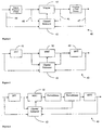
- Communication systems may be modelled in terms of a transmitter 10 and receiver 30, separated by a channel 20, as shown in Figure 1 .
- the transmitter 10 transforms the data into a signal suitable for transmission over the channel 20.
- the channel may distort the transmitted signal in some way.
- the receiver's goal is to remove the effects of the channel distortions from the signal and to transform the signal into an estimate of the original data.
- the receiver may include a Channel Estimator.
- the Channel Estimator may observe a received signal that has been distorted by transmission over the channel, and generate a channel estimate based upon this observation.
- Channel distortions may include amplitude distortions, frequency offsets, phase offsets, Doppler effects, or distortions resulting from a channel with memory, such as Rayleigh fading, Rician fading, or multipath channels, or additive noise or interference.
- the receiver may use the channel estimate to remove the effect of the channel and generate an estimate of the data that was transmitted.
- the channel estimate would be perfect, and the estimate of the transmitted data would be optimal.
- channel estimates may not be perfect, so the estimate of the transmitted data may be sub-optimal.
- many receivers are designed for operation over a narrow range of channel types. If these receivers are used to receive data transmitted over types of channels they were not designed for, then their channel estimators may be more likely to generate erroneous channel estimates, thereby degrading performance.
- DVD-H Digital Video Broadcast Handheld
- ETSI European Telecommunications Standard Institute
- DVB-H aims to specify an efficientt means for broadcasting multimedia services to battery-powered handheld terminals.
- DVB-H is backward compatible with its terrestrial predecessor.
- Aims of the DVB-H standard include:
- the standard includes the components described in Table 1.
- Table 1 DVB-H Specific Components Component Layer Mandatory/ Optional Stated Aim Time-Slicing Link Mandatory Reduce average power consumption and allow seamless handover.
- MPE-FEC Link Optional Improve C/N and Doppler performance in mobile channels, and improve tolerance to impulse Interference.
- In-depth Symbol Interleaver PHY Optional Improved robustness for 2K, 4K modes.
- the DVB waveform may suffer from Inter-Carrier Interference (ICI) where, due to mobility-induced Doppler, subcarriers interfere with each other.
- ICI Inter-Carrier Interference
- the DVB-H standard extends DVB-T by addition of a "4K" mode to the 2K and 8K modes.
- the number here refers to the number of subcarriers in the FFT used to generate the transmitted DVB waveform. For a given bandwidth signal more subcarriers means closer subcarriers and higher vulnerability to Doppler.
- the 8K mode is particularly vulnerable to Doppler.
- the 4K mode is seen as a compromise between wider subcarriers, as offered by the 2K mode, and the longer cyclic prefix offered by the 8K mode.
- DVB also has a hierarchical mode where a waveform may be demodulated in two ways.
- One method results in more reliable demodulation at a lower data rate and the other is more difficult to demodulate but results in higher data rates.
- An ability to demodulate in higher data rate modes offers improved service to end users.
- Pilot symbols are inserted in the transmitted waveform in order to enable channel estimation for coherent demodulation and decoding at the receiver.
- OFDM Orthogonal Frequency-Division Multiplexing
- EP 0 838 928 A2 describes a method and apparatus for receiving digital signals transmitted with C-OFDM (Coded Orthogonal Frequency-Division Multiplex) modulation. This involves a channel estimation method known as CD3-OFDM, which uses the OFDM symbol received in the previous step, after correction, re-encoding and re-modulation.
- CD3-OFDM Coded Orthogonal Frequency-Division Multiplex
- WO 2006/092877 A1 describes that a receiver apparatus, which is compliant with a wireless communication system employing a multicarrier modulation scheme, performs DFT of a received signal from which particular signals have been removed so as to eliminate the influences of delay waves.
- a part estimates a propagation channel, a part reproduces, based on information of the estimated channel, a pilot signal included in the received signal; a part, assuming that the pilot signal included in the received signal is a null carrier, generates a frequency equalization matrix based on the foregoing channel information, a part subtracts the reproduced pilot signal from the DFT result; and an EMM part multiplies the frequency equalization matrix by the signal obtained by the foregoing subtraction.
- the equalizer has a cascade structure of an AR prefilter and a FIR adaptive equalizer.
- the AR prefilter is designed using the channel impulse response estimated by the channel estimator.
- US 2003/0039203 discloses a preamble-based frequency domain equalization for IEEE 802.11a compliant networks.
- Embodiments of a pre-processor are described that may be placed before a communications receiver in a communications network to improve the performance of the receiver.
- the pre-processor modifies the communication channel observed by the receiver to better match the capability of the receiver.
- the described pre-processor has potential application to:
- the pre-processors may be used to modify the signal input to the receiver in order to improve system performance. This is illustrated in Figure 2 .
- the Pre-Processor 40 takes the signal that has been affected by the channel 20 and processes the signal such that the signal output to the receiver 30 appears to have been affected by a different channel, where that channel is matched to the capabilities of the receiver 30.
- the use of the Pre-Processor 40 expands the range of channels that an existing receiver can operate with. In the cases where the existing receiver cannot be easily modified (such as when the existing receiver is an application specific integrated circuit (ASIC)), the receiver may fail to meet performance requirements on channels beyond its capabilities. In these cases the Pre-Processor 40 can be added prior to the existing receiver to expand the range of channels the receiver 30 can operate with.
- ASIC application specific integrated circuit
- the Pre-Processor 40 makes an estimate of the channel 20 based upon the received signal. It then uses this channel estimate to remove or modify the effect of the channel.
- a goal of the Pre-Processor 40 is to put the input to the receiver into such a form that the effective channel that the receiver observes is within the range that the receiver is capable of operating with.
- Figure 3 shows a block diagram for the Pre-Processor 40 implemented in the time domain.
- Inputs to the pre-processor 40 are provided to a channel estimator 42 and a filter 41.
- the channel estimator 42 takes inputs that are in the time domain and the estimator output is used by module 39 to calculate the filter coefficients for a time domain filter 41 that modifies the received signal such that it appears to have been affected by a different channel than the actual channel in the communications system.
- the output of the filter 41 is provided to the receiver 30.
- Figure 4 shows a general block diagram for another Pre-Processor 40 implemented in the frequency domain.
- the received signal is first transformed from the time domain to the frequency domain.
- a mapper block 43 modifies the frequency domain signal such that it appears to have been affected by a different channel than the actual channel 20 in the communications system, and then this signal is transformed back to the time domain and output.
- the channel estimator 42 uses as input the received signal 44 in the time domain, or the deceived signal 45 in the frequency domain, or the received signal in both the time domain and the frequency domain 44, 45.
- the channel estimator 42 may optionally also use the mapped signal 46 in the frequency domain, or the mapped signal 47 in the time domain, or the mapped signal in both the frequency domain and the time domain 46, 47.
- the mapping performed by the mapper block 43 is based on the channel estimate generated by channel estimator 42.
- Figure 5 shows a block diagram of a variant of the frequency domain.
- Pre-Processor structure 40 Here the time domain to frequency domain transformation is performed using a fast Fourier transform (FFT) 48, and the frequency domain to time domain transformation is performed using an inverse fast Fourier transform (IFFT) 49.
- FFT fast Fourier transform
- IFFT inverse fast Fourier transform
- the frequency domain received signal is combined with the output of the channel estimator block 42 using a maximum ratio combiner (MRC) 50.
- the channel estimator 42 uses as input the received signal in the time domain, or the received signal in the frequency domain, or the received signal in both the time domain and the frequency domain.
- the channel estimator may optionally also use the MRC output signal in the frequency domain, or the MRC output signal in the time domain or the MRC output signal in both the frequency domain and the time domain.
- Figure 6 shows a block diagram of another variant of the frequency domain Pre-Processor structure.
- the modified input signal output by the MRC 50 in the frequency domain is first demodulated and then remodulated, before being used to direct the channel estimator 42.
- the channel estimator 42 uses as input the received signal in the time domain, or the received signal in the frequency domain, or the received signal in both the time domain and the frequency domain.
- the channel estimator may optionally also use the remodulated signal in the frequency domain, or the remodulated signal in the time domain, or the remodulated signal in both the frequency domain and the time domain.
- Figure 7 shows a block diagram of yet another variant of the frequency domain Pre-Processor structure.
- the modified input signal output by MRC 50 in the frequency domain is first demodulated, then decoded and re-encoded in the forward error control (FEC) block 51, and then remodulated, before being used to direct the channel estimator 42.
- the channel estimator 42 uses as input the received signal in the time domain, or the received signal in the frequency domain, or the received signal in both the time domain and the frequency domain.
- the channel estimator 42 may optionally also use the remodulated signal in the frequency domain, or the remodulated signal in the time domain, or the remodulated signal in both the frequency domain and the time domain.
- the FFT 48 and IFFT 49 may be replaced with any form of time to frequency domain conversion, or frequency to time domain conversion, respectively.
- the MRC 50 may be replaced by any form of signal combiner, such as a minimum mean square error (MMSE) combiner, or zero forcing combiner.
- MMSE minimum mean square error
- a frequency offset channel introduces a frequency offset to the signal that is transmitted, If the receiver can accurately estimate the frequency offset then the effect of the channel can be removed.
- a receiver 30 that has been designed to operate with frequency offsets up to 10 kHz. If the frequency offset is, say, 100 kHz then the performance is likely to be very poor. If instead a channel estimator 42 is used in the Pre-Processor 40 that can cope with a frequency offset of 100 kHz, then the Pre-Processor could remove the effects of the channel. This would allow an existing receiver that can only cope with 10 kHz frequency offsets to be used on channels with frequency offsets of up to 100 kHz, thereby expanding the range of channels that the existing receiver can operate with.
- Satellite channels are characterised by Rician fading with path delay, as illustrated in Figure 8 .
- a typical maritime (i.e. ships at sea communicating via a geostationary satellite) satellite channel has a K-factor of 10 dB, a fading bandwidth of 0.7 Hz, and a path delay of 0 ⁇ s.
- a typical aeronautical (i.e. planes in the air communicating via a geostationary satellite) satellite channel may have a K-factor of 20 dB, a fading bandwidth of 100 Hz, and a path delay of 15 ⁇ s.
- a receiver designed for operation with a maritime satellite channel may not cope with the harsher aeronautical satellite. In this case a Pre-Processor 40 can be added prior to a receiver 30 designed for maritime satellite channels to allow the receiver 30 to perform well on an aeronautical satellite channel,
- Yet another example channel 24 that the Pre-Processor 40 could be applied to is the channel experienced by IEEE 802.11a radios, described for example in IEE 802.11 WG, "IEEE 802.11 Wireless Local Area Networks (WLAN),” http://grouper.ieee.org/groups/802/11/.
- IEEE 802.11a radios described for example in IEE 802.11 WG, "IEEE 802.11 Wireless Local Area Networks (WLAN),” http://grouper.ieee.org/groups/802/11/.
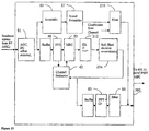
- a conventional IEEE 802.11a transmitter and receiver are illustrated in Figure 9 .
- the transmitter implements a sequence of operations on the input data, ie scramble, FEC encode, interleave, modulate, IFFT, add cyclic prefix, upsample and filter.
- the resultant signal is transmitted over a transmission channel and a complementary receiver acts to filter and downsample the received signal, which is synchronized has the cyclic prefix removed and transformed to the frequency domain by an FFT.
- the output of, the FFT is provided to a channel estimator and a demodulator, which uses the output of the channel estimator.
- the demodulated signal is deinterleaved, FEC decoded and descrambled.
- Conventional IEEE 802.11a receivers are designed for indoor, low mobility channels characterised by low RMS delay spread (e.g. ⁇ 200 ns) and low Doppler frequency (e.g. ⁇ 300 Hz), When these receivers experience outdoor, high mobility channels they may fail.
- channel estimators and signal processors can be implemented that are able to cope with the high RMS delay spread and high Doppler frequency of outdoor, mobile channels.
- the Pre-Processor may reduce the effect of the channel to the point where the existing IEEE 802.11a receiver can cope with it.
- a Pre-Processor allows conventional IEEE 802.11a ASIC receivers that have been designed for indoor, low mobility channels to be used on outdoor, highly mobile channels.
- the exemplary embodiments described below are all IEEE 802.11a Pre-Processors. However, these techniques may also be applied to other communications systems.
- the described pre-processors are relevant to communications receivers that include a Radio Frequency (RF) circuit, a Medium Access Control (MAC) circuit and a Physical Layer (PHY) circuit. Protocols that include RF/PHY/MAC include IEEE 802.16 and IEEE 802.11-
- the described pre-processors may also be used in DVB-H and DVB-T contexts, which contain RF/PHY. Other relevant applications that may use the pre-processors, such as ADSL and Homeplug only contain PHY/MAC.
- the pre-processors described herein may be implemented in hardware, for example application-specific integrated circuits (ASICs).
- ASICs application-specific integrated circuits
- Other hardware implementations include, but are not limited to, field-programmable gate arrays (FPGAs), structured ASICs, digital signal processors and discrete logic.
- the pre-processor may be implemented as software, such as one or more application programs executable within a computer system.
- the software may be stored in a computer-readable medium and be loaded into a computer system from the computer readable medimn for execution by the computer system.
- a computer readable medium having a computer program recorded on it is a computer program product. Examples of such media include, but are not limited to CD-ROMs, hard disk drives, a ROM or integrated circuit.
- Program code may also be transmitted via computer-readable transmission media, for example a radio transmission channel or a networked connection to another computer or networked device.
- the Pre-Processor 40 is designed to remove the effects of multipath and mobility from IEEE 802.11a channels and present the modified signal to an IEEE 802.11a receiver for subsequent demodulation and processing.
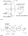
- a typical implementation of an IEEE 802.11 node 53 is shown in Figure 10a .
- an off-the-shelf IEEE 802.11 RF ASIC 55 downconverts the signal received on the antenna 54 to baseband and passes this signal to an off-the-shelf IEEE 802.11 PHY/MAC ASIC 56, which processes the signal and outputs the data to the user via a number of possible interfaces.
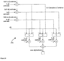
- a model for an IEEE 802.11 node 60 incorporating an ASIC implementation of the Pre-Processor 40 is shown in Figure10b (other implementations are possible).
- two off-the-shelf IEEE 802.11 RF ASICs 63, 64 downconvert the signal received on two separate antennas 61, 62 to baseband and pass these signals to the Pre-Processor 40.
- the Pre-Processor 40 combines these two signals and removes some or all of the effect of the channel from the resultant signal before passing the processed signal to an off-the-shelf IEEE 802.11 PHY/MAC ASIC 56, which processes the signal as before and outputs it.
- the depicted embodiment of the Pre-Processor 40 uses signals from two antennas 61, 62, but it could also use one antenna or more than two antennas. Other embodiments may perform antenna selection as an alternative to signal combining.
- FIG. 11 A possible embodiment of a system of IEEE 802.11 nodes incorporating the Pre-Processor is shown in Figure 11 .
- This figure shows that Pre-Processor enabled nodes 70 can co-exist in an IEEE 802.11 network with standard (i.e. non-Pre-Processor enabled) nodes 72.
- the Pre-Processor uses analogue baseband inputs and outputs.
- the Pre-Processor uses analogue baseband inputs and outputs.
- the Pre-Processor 40 may pass signals through without modification (except perhaps some delay) to the existing receiver 30. This bypass mode also allows the operation of the Pre-Processor enabled node 70 to be indistinguishable from a standard node (i.e. a non-Pre-Processor enabled node) 72.
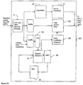
- Figure 12 shows the preferred embodiment 80 of the IEEE 802.11a Pre-Processor.
- This embodiment uses algorithms derived from those defined in USA patent application publication US2004/0264561 "Filter structure for iterative signal processing" published on 30 December 2004, Australian provisional patent application 2005904528 filed 22 August 2005 and related PCT application PCT/AU2006/001201 (publication number WO 2007/022564 A1 ), PCT application PCT/AU2007/000231 (publication number WO 2007/095697 A1 ) "Method and system for communication in a wireless network” filed 27 February 2007 and PCT/AU2007/000722 (publication number WO 2007/134406 A1 ) "Method and apparatus for multicarrier communications” filed 24 May 2007.
- Pre-processor 80 takes the baseband signals from two RF ASICs (eg 63, 64) and performs automatic gain control (AGC), DC offset removal, and filtering in block 81.
- the filtered signal is output to the acquisition block 82, which identifies the beginning of the valid transmitted frame. If the frame is valid, it is converted from the time domain to the frequency domain using a fast Fourier transform (FFT) 48.
- FFT fast Fourier transform
- the outputs from the FFT block 48 go to both the Channel Estimator block 42, and a linear combiner block 83, which in the depicted arrangement is a maximal ratio combiner (MRC) block.
- the maximal ratio combiner block 83 combines the outputs of the FFT block 48 and the channel estimator block 42.
- the outputs of the MRC block 83 are fed to the forward error correction (FEC) block 84.
- the outputs of the FEC block 84 are then used to direct the Channel Estimator 42. They are also passed to the Inverse FFT (IFFT) block 85 where they are converted back into the time domain, and the cyclic prefix (CP) inserted.
- the output of block 85 is filtered in block 86 and output from the Pre-Processor 80.
- the linear combiner block 83 may use a minimum mean square error (MMSE) algorithm, or a zero forcing algorithm as an alternative to the maximal ratio algorithm.
- MMSE minimum mean square error
- the FEC block 84 may use either a Viterbi decoder block, a re-encoder/mapper block, and an optional LLR calculator block ( Figure 13 ), or an a posteriori probability (APP) decoder block, a re-encoder/mapper block and optional LLR calculator ( Figure 14 ).
- a Viterbi decoder block a re-encoder/mapper block, and an optional LLR calculator block
- APP a posteriori probability
- a second FEC decoder is used before re-encoding, as shown in PCT/AU2007/000722 (publication number WO 2007/134406 A1 ), which claims priority from Australian provisional patent application 2006902812 . This introduces more latency, but increases decoding gain.
- the initial acquisition is detected by counting the number of descenders from a peak value (see Figure 15 ). The peak value must be above a predefined threshold before the descender count is incremented. Once the number of descenders exceeds a threshold then acquisition is deemed to have occurred.
- the latency for the short preamble initial acquisition decision is 32 samples @ 20MHz into the Long Preamble. This delay is 1.6 ⁇ s after the start of the short preamble or 9.6 ⁇ s after the start of the Packet.
- Pre-Processor 80 stored preambles are used to reduce latency.
- short and long preambles are stored in the data store 87 and are output once the Pre-Processor 80 has acquired the incoming packet. This means that the Pre-Processor 80 can start outputting the preamble with reduced delay.
- the preambles received from the channel are passed through to the output of the Pre-Processor.
- the stored or passed through preambles are processed in order to ensure continuity in the channel that the MAC/PHY ASIC sees. Since the MAC/PHY ASIC 56 still performs its own channel estimate and removal on the signal, the ASIC 56 may be presented with a signal which it can demodulate without performance loss.
- the pre-processor 80 outputs a reduced number of short preamble sub-words, where the short preamble is constructed of 10 repetitions of the sub-word.
- the structure of the IEEE 802.11a preamble is shown in Figure 16 .
- the acquisition delay is reduced by beginning to output the short preamble to the MAC/PHY ASIC 56 immediately that a packet is detected. Then, once the timing has been determined from the long preamble the Pre-Processor 80 can stop transmitting the short preamble and start transmitting the stored long preamble.
- the transmission can commence in one of two ways. Firstly it can commence on the boundary of a short preamble sub-word. Secondly sub-word boundaries are ignored allowing the long preamble to begin transmission at the correct position as indicated by the timing of the received packet irrespective of the short preamble sub-word.
- the acquisition delay is reduced by continuously transmitting a stored short preamble to MAC/PHY ASIC 56 even when there is no packet present. Then, once the actual packet is detected the short preamble is stopped at an appropriate position and the long preamble and remainder of the packet transmitted to MAC/PHY.
- Figure 17 shows an alternate embodiment 90 of an IEEE 802.11a Pre-Processor that has low latency.
- the outputs 91 of maximum ratio combiner 83 are passed directly (or via a buffer) to the IFFT block 85, thereby reducing processing delay.
- Figure 18 shows an alternate embodiment 100 of an IEEE 802.11a Pre-Processor that has low latency.
- the effects of the channel are reduced or eliminated using a time domain filter102.
- the coefficients of the time-domain filter 102 are generated by filter coefficient generator 104, which receives an output from the channel estimator 42.
- the output of the time domain filter 102 is passed to the output of the pre-processor 100.
- FIG 19 shows an alternate embodiment 200 of an IEEE 802.11a Pre-Processor structure which performs either soft or hard re-modulation and processing in the frequency domain before retransmitting the data.
- This structure uses a soft-input soft-output (SISO) FEC block 212 that receives an output from the MRC block 83.
- the decoder in the SISO FEC block could be any SISO decoder, such as a soft-output Viterbi algorithm (SOVA) or APP decoder.
- SOVA soft-output Viterbi algorithm
- APP decoder The output of the SISO FEC 212 is processed by the soft/hard decision re-modulator 214, which in turn directs the channel estimator 42.
- the output of the re-modulator 214 is also passed to the IFFT block 85.
- the preambles are processed by filter 210, coefficients for which are provided by the channel estimator 42.
- the IEEE 802.11a standard specifies that acknowledgement (ACK) frames commence transmission within one short interframe space (SIFS) of the end of the corresponding data frame being received.
- SIFS time is defined to be 16 ⁇ s.
- the IEEE 802.11j modification of the IEEE 802.11a standard introduced Coverage Classes, which are a mechanism to compensate for air propagation time of signal. In the described embodiments of the IEEE 802.11a Pre-Processor, if there exists any delay in excess of the SIFS time, such a delay is compensated for by increasing the Coverage Class by an amount at least equal to the delay.
- IEEE 802.11 MAC/PHY ASICs 56 have a programmable SIFS time, and can have their SIFS time reduced to a value less than 16 ⁇ s.
- the IEEE 802.11a Pre-Processor if there exists any delay in excess of the SIFS time of the Pre-processor ASIC and MAC/PHY ASIC combination, then such a delay or part thereof, is compensated by reducing the programmable SIFS time of the MAC/PHY ASIC 56.
- the IEEE 802.11standard specifies that ACK frames are transmitted within SIFS (16 ⁇ s) of the end of the previous frame. However, no other transmitters under control of a distributed control function (DCF) will transmit on the channel until DCF interframe space (DIFS, 34 ⁇ s) after the previous frarne. This is to allow transmitters under control of a point control function (PCF) to transmit PCF interframe space (PIFS, 25 ⁇ s) after the previous frame.
- PCF point control function
- PCF PCF interframe space
- PIFS PCF interframe space
- the IEEE 802.11a standard supports several PHY data rates (6, 9, 12, 18, 24, 36, 48, and 54 Mbps).
- the IEEE 802.11a Pre-Processor shown in Figure 12 it is not necessary that the re-encoding and re-mapping of output signal is at the same data rate as the input signal.
- Some of the delay in excess of the SIFS time may be compensated by outputting the delayed output signal at a higher data rate in such a way as to ensure that the end of the frame at the output of the Pre-Processor is as close as possible to the end of the frame at the input to the Pre-Processor.
- the receiver In order for the slot timing mechanism in the IEEE 802.11a standard to work correctly, the receiver must be able to detect the presence of another 802.11a signal within the clear channel assessment (CCA) time (CCA_time). For IEEE 802.11a the detection time is 4 ⁇ s.
- IEEE 802.11 MAC/PHY ASICs typically use a received signal strength indicator (RSSI) from an IEEE 802.11 RF ASIC to perform CCA.
- RSSI received signal strength indicator
- One embodiment of the IEEE 802.11a Pre-Processor forces the CCA_busy state in the MAC/PHY ASIC 56 by setting this RSSI input to a level above the CCA_power_threshold (the standard requires that any signal greater than - 62dBm should generate a CCA_busy state), This means that the CCA circuit of the MAC/PHY ASIC 56 is not affected by the delay of the Pre-Processor.
- the status and control signals (such as the RSSI signal) from the IEEE 802.11 RF ASIC (eg 63, 64) are input to the Pre-Processor ASIC 40, delayed such that they are aligned to the output signal of the pre-processor 40, and output to the IEEE 802.11a MAC/PHY ASIC 56.
- the receiver performance may be improved by predicting and removing Inter-Carrier Interference (ICI), as described below.
- ICI Inter-Carrier Interference
- a channel for Orthogonal Frequency Division Multiplexing (OFDM) affected by ICI may be modelled using a matrix model where an interference matrix models the transform of the transmitted symbols to an equivalent set of received symbols.
- OFDM Orthogonal Frequency Division Multiplexing
- the matrix has non-zero off-diagonals, ICI results.
- the dominant interfering terms are the principal off-diagonals describing Interference from adjacent subcarriers.
- Estimates of h 0 [i] may be referred to herein as direct channel estimates.
- Estimates of h -1 [i] and h +1 [i] may be referred to as intercarrier interference channel estimates.
- modules A, module B and module C The system and method for ICI removal are described with reference to three modular building blocks, designated module A, module B and module C respectively.
- the modules may be implemented in hardware, for example application-specific integrated circuits (ASICs).
- ASICs application-specific integrated circuits
- Other hardware implementations include, but are not limited to, field-programmable gate arrays (FPGAs), structured ASICs, digital signal processors and discrete logic.
- the modules may be implemented as software, such as one, or more application programs executable within a receiver system.
- the software may be stored in a computer-readable medium and be loaded into a receiver system from the computer readable medium for execution by the receiver system.
- a computer readable medium having a computer program recorded on it is a computer program product.
- Program code may also be transmitted via computer-readable transmission media, for example a radio transmission channel or a networked connection to another computer or networked device.
- the ICI removal may be carried out in a receiver unit or in a pre-processor associated with a receiver unit.
- Fig 21 shows a functional block diagram of a module 300 (designated Module A) that operates to apply FEC constraints
- the inputs to the FEC module 300 are a transmitted symbol estimate d ⁇ [ i ] 270, a set of channel estimates ⁇ 0 [ i ], ⁇ -1 [ i ] and ⁇ +1 [ i ] 260 and the received signal r[i].
- the output of FEC module 300 is an information bit sequence and (optionally) transmitted symbol estimates.
- the FEC module 300 includes a functional block 310 (the ICI Cancel and Combine block).
- the shift(x,m) function executes the cyclic rotation of the vector by m steps described above, * indicates a conjugate transpose.
- the output of the ICI Cancel and Combine block 310 is provided to Demodulation module 320.
- the FEC Decoding 330 uses the output of demodulator 320 to generate information bit estimates. If the FEC decoding 330 employs soft output methods (e.g. A-Posteriori Probability (APP) decoding using the forward backward algorithm) then hard and soft transmitted symbol estimates may be generated using hard and soft remodulators 340. If hard decision decoding (such as Viterbi decoding) was used in the FEC decoder 330 then hard remodulation may be applied in block 340 to generate a hard estimate of the transmitted symbol, In any case pilot symbols (known a priori) should be inserted in the estimate.
- Soft output methods e.g. A-Posteriori Probability (APP) decoding using the forward backward algorithm
- hard and soft transmitted symbol estimates may be generated using hard and soft remodulators 340.
- hard decision decoding such as Viterbi decoding
- hard remodulation may be applied in block
- the slicer may produce hard or soft decisions. Hard decisions from a "slicer” can be generated by computing the constellation point with minimum distance to the received point given the channel model. Soft decisions from a "slicer” can be generated by computing the likelihood for each constellation, point given the channel model and then computing the average symbol.
- Figure 22 shows a functional block diagram of a Direct Channel Estimator 400 (designated Module B).
- An ICI cancel block 410 subtracts the ICI estimates from the received signal r[i], as illustrated in Figure 23 .
- the training block 420 generates the element-by-element multiplication with the inverse of the hard estimate, inv(d[i]), and the output of the training block 420 is smoothed by the smoothing block 430 to produce an estimate 280 of the direct component channel, h 0 [i].
- smoothing techniques may be used, including convolution by a low-pass filter.
- Another smoothing option is to transform the estimates using an FFT, window the transform and then apply an IFFT. Equation 2 reflects the combined operation of blocks 410, 420 and 430,
- the direct channel estimator processing element 400 for a given OFDM symbol i is shown in more detail in Figure 22 excluding the smoothing function 430.
- Figure 24 shows a functional block diagram of an ICI Channel Estimator 500 (designated module C).
- the inputs to the ICI Channel Estimator 500 are the received symbol r[i] 250, a transmitted symbol estimate d ⁇ [ i ] 270 and a direct channel estimate ⁇ 0 [ i ] 260.
- Eqs. 3a and 3b reflect the overall operation of functional blocks 510, 520 and 530 of the ICI Channel Estimator 500.
- the 'Direct Cancel' block 510 implements the expression within round brackets that subtracts the contribution of the direct channel and one of the ICI terms from the received symbol r[i].
- the training block 520 implements the element-by-element multiplication of the respective outputs of block 510 with an inverse of the symbol estimates d. 1 [i] or d +1 [i].
- the raw outputs of block 520 (ie estimates of h -1 [i] and h +1 [i]) are smoothed in smoothing block 520.
- the smooth function may be implemented in the time or frequency domain. The bandwidth of the smoothing may be set according to the coherence frequency of the radio channel.
- the inv function computes (or obtains via a lookup table) the inverse of the symbols. For example, if the transmitted symbol on a subcarrier was (1+j)/sqrt(10) then the inverse (that forces the product to unity) is sqrt(5/2)(1-j).
- the ICI channel estimator processing element 500 for a given OFDM symbol i is shown in Figure 24 , excluding the smoothing function 530. In the depicted arrangement soft estimates of the transmitted symbols are used as inputs to block 510, and hard estimates are used for the training block 520.
- Figure 26 is a schematic representation of a schedule 702 for decoding a received OFDM symbol 250. It is assumed that the OFDM symbol 250 is subject to convolutional coding, interleaving and modulation at the transmitter.
- the schedule 702 may be implemented at the receiver using the modules A, B and C described above.
- All estimate memories are initialised to zero, including the Direct Channel Estimate, transmitted symbol estimate and ICI channel estimate.
- Inputs to the schedule 702 include a received OFDM symbol 250 and pilot symbols 704.
- the receiver obtains a first Direct channel estimate using the received output r[i] 250, and the pilot symbols 704.
- the output r[i] may be a frequency-domain version output from a FFT (not shown).
- the initial estimate of the direct channel may be obtained in stage 710 by first removing the effect of the Transmitted pilots 704 on the corresponding subcarrier in the received OFDM symbol 250. This is typically done, for Phase Shift Keyed (PSK) modulation, via multiplication with the conjugate of the transmitted pilot. This may be implemented using the training block 420.
- the resulting raw estimate of the direct channel may then be smoothed, for example using block 430 to obtain a channel estimate for the data bearing subcarriers.
- PSK Phase Shift Keyed
- the next stage 714 of schedule 702 uses the first Direct Channel estimate 260 output from stage 710 and the first transmitted symbol estimate 270 output from stage 712 to generate a second estimate 280 of the Direct Channel.
- the stage 714 may be implemented using Module B 400.
- stage 716 uses Module A 300 to demodulate and decode the OFDM symbol 250 using the second Direct Channel Estimate 280 to obtain a second transmitted symbol estimate (including pilot insertion).
- Stage 716 may output both a hard frequency domain estimate and a soft frequency domain estimate of the transmitted symbol.
- the next stage 718 of schedule 702 may be implemented using Module B 400 and Module C 500.
- Inputs to stage 718 include the second direct channel estimate from stage 714 and the second transmitted symbol estimate from stage 716.
- the second Direct Channel estimate 280 and the second transmitted symbol estimate 270 are provided to Module B 400 to generate a third estimate of the Direct Channel 280.
- the third Direct Channel estimate 280 and the second transmitted symbol estimate 270 are provided to Module C 500 to generate a first ICI channel estimate 290.
- Stage 720 uses module A 300 without the retransmission stage 340 to demodulate and decode the OFDM symbol 250 using the third Direct Channel Estimate 280 and the first ICI channel estimate 290 to obtain a final information bit estimate. Stage 720 uses the soft frequency domain symbol estimate output in stage 716.
- Figure 26 shows the schedule 702, which uses soft decisions.
- Figure 28 is a schematic illustration of a schedule 750 that is similar to schedule 702 but does not use soft decisions.
- Inputs include pilot symbols 704 and the received OFDM symbol 250.
- Stage 752 provides an initial estimate of the direct channel based on the pilot symbols.
- Stage 754 then provides a first estimate of the transmitted OFDM symbol,
- Stage 756 then provides an updated estimate of the direct channel and stage 758 provides a second estimate of the frequency domain OFDM symbol.
- Stage 760 provides a further estimate of the direct channel and provides an estimate of the ICI channel characteristics, which are used in stage 762 to cancel the ICI effects and to output a final estimate of the transmitted symbol.
- the stages 754, 756, 758,760 and 762 each include indicia to show which of Modules A, B and C (300, 400, 500) may be utilised to perform the operations required in each of the stages.
- Stage 754 uses Module A 300
- stage 756 uses Module B 400
- stage 758 uses Module A 300
- stage 760 uses modules B 400 and Module C 500
- stage 762 uses blocks from Module A 300.
- Schedules 702 and 750 may be summarised by the sequence ABABCA.
- Modules A, B, C are identical, i.e. they update a set of channel estimates and a transmitted symbol estimate, other schedules are anticipated. (The module definitions allow for zero inputs, which are encountered during the initial phases of processing).
- schedules 702 and 750 are ABABCA
- schedules 702 and 750 are ABABCA
- Figure 29 illustrates a schedule 770 that uses the sequence ABACA. This differs from sequences 702 and 750 in that there one less update of the direct channel estimate.
- Stage 772 provides an initial estimate of the direct channel based on the pilot symbols, as discussed with reference to stage 710.
- Stage 774 then provides a first estimate of the OFDM symbol, which is used by stage 776 to update the estimate of the direct channel.
- Stage 778 then updates the symbol estimate and stage 780 generates an estimate of the ICI effects.
- stage 782 uses the ICI estimates from stage 780 and the direct channel estimates from stage 776 to cancel the estimated ICI effects and provide a final estimate of the transmitted symbol.
- Figure 30 illustrates a schedule 790 that uses the sequence ABCA.
- Stage 792 provides an initial estimate of the direct channel based on the pilot symbols, as discussed with reference to stage 710.
- Stage 794 then provides a first estimate of the OFDM symbol, which is used by stage 796 to update the estimate of the direct channel and also to generate an ICI estimate.
- Stage 796 uses Modules B and C.
- Stage 798 uses the ICI estimates and the direct channel estimates from stage 796 to cancel the estimated ICI effects and provide a final estimate of the transmitted symbol,
- the FEC decoder 330 in Module A 300 may output soft estimates of the encoder output bits. These soft output bits may be used to generate an estimate of the transmitted OFDM symbol.
- the soft bits are soft modulated 340 by computing the average position on the constellation map over the bit PDFs of the bits corresponding to the symbol. Pilot symbols (known a priori) are also inserted.
- the FEC decoder 330 may simultaneously output hard decisions.
- soft symbols are used for interference cancellation and hard symbols for training.
- soft symbols for interference cancellation is that if the decoder is uncertain, the soft symbols are small, which may improve the accuracy of the interference cancellation step. If hard symbols are used for training then symbol inverses can be stored in a lookup table in the receiver.
- n ⁇ i r i ⁇ h ⁇ ⁇ 1 i d ⁇ ⁇ 1 i ⁇ h ⁇ 0 i d ⁇ 0 i ⁇ h ⁇ + 1 i d ⁇ + 1 i which is the received symbol minus all of the signal components that are modelled.
- An estimate of the direct component can be obtained by adding the direct component estimate ⁇ 0 [ i ] d ⁇ 0 [ i ] to the noise estimate n ⁇ [ i ]. Any of the ICI terms can be generated in a similar manner.
- Any update that a module makes may be in terms of a difference term caused by the subset of parameters that the module has modified.
- the performance of the FEC Module (A) 300 may be improved through use of any known encoder input bits.
- DVB SYNC Bytes are encoded. These will force the Convolutional Code into known states. For example, this information can be employed in both Viterbi and APP decoders of the Convolutional code.
- APP decoding the information bit priors are set according to the SYNC Byte values.
- Viterbi decoding the known bits can be used to execute terminated traceback.
- the ICI present in the output of an FFT in the receiver system is also reduced by feeding back local frequency-offset estimates to a pre-FFT module that corrects the time domain sequence for the measured frequency offset.
- This correction may be performed in a forward-only manner or retrospectively, i.e. any given OFDM symbol may be transformed through the FFT multiple times if the frequency offset estimate changes during application of the receiver.
- the quantities derived as part of either of the channel estimation modules 400, 500 may be used to form a Frequency offset estimate.
- the phase change will, in general, change from OFDM symbol to symbol.
- the time domain correction for the frequency offset can be based on an interpolation of ⁇ [ i ] for a set of sample points between adjacent OFDM symbols. In this way the frequency for which the time domain signal is correct can change at a rate higher than the OFDM symbol period.
- the soft output FEC decoder 330 may be used to mark erasures for an outer Reed Solomon (RS) erasure decoder, and may improve the error correction capability of the Reed Solomon outer code. Soft outputs may be used to assign reliability to RS codeword symbols, and some number of the least reliable symbols may then be marked for erasure at the input to the RS decoder.
- the RS erasure decoder may run be for one or more iterations, where the number of erasures marked in each successive iteration is reduced, until some minimum value. In the case where the minimum value is zero, operation is equivalent to that of an error-correcting RS decoder.
- the iterative loop may be terminated early in the case when the decoder reports a successful decode.
- the number of iterations employed, and the number of symbols to be marked for erasure at each iterative step may either be fixed or dynamically updated according to some system state metric.
Claims (27)
- Preprocessor (40) zum Arbeiten in Verbindung mit einem Kommunikationsempfänger (30), der ein Daten enthaltendes Signal empfangen und das Signal in eine Schätzung der ursprünglichen Daten umwandeln kann, wobei der Preprocessor Folgendes umfasst:einen Eingang mit der Aufgabe, ein über einen Kommunikationskanal (20) gesendetes Eingangssignal zu empfangen;einen Kanalschätzer (42) mit der Aufgabe, wenigstens ein Merkmal des Kommunikationskanals auf der Basis des Eingangssignals und eines Rückmeldesignals zu schätzen;einen Signalmodifizierer mit der Aufgabe, das Eingangssignal in Abhängigkeit von dem wenigstens einen geschätzten Merkmal zu modifizieren, wobei der Kanalschätzer und der Signalmodifizierer ohne Rückmeldung vom Kommunikationsempfänger (30) arbeiten, wobei der Signalmodifizierer eine FEC-(Vorwärtsfehlerkorrektur)-Einheit (51) zum Ableiten des an den Kanalschätzer (42) angelegten Rückmeldesignals umfasst, wobei das Modifizieren das FEC-Decodieren und -Recodieren durch die FEC-Einheit (51) beinhaltet; undeinen Ausgang zum Anlegen des modifizierten Signals an den Kommunikationsempfänger.
- Preprocessor nach Anspruch 1, wobei der genannte Signalmodifizierer ein Zeitdomänenfilter (41) umfasst.
- Preprocessor nach Anspruch 2, der ferner Folgendes umfasst:einen Koeffizientenkalkulator mit der Aufgabe, einen oder mehrere Koeffizienten des genannten Zeitdomänenfilters auf der Basis eines Ausgangs des genannten Kanalschätzers zu bestimmen.
- Preprocessor nach Anspruch 1, der Mittel (48) zum Umwandeln von Signalen von der Zeitdomäne in die Frequenzdomäne umfasst, wobei der genannte Signalmodifizierer die Aufgabe hat, das Eingangssignal in die Frequenzdomäne zu modifizieren.
- Preprocessor nach Anspruch 4, wobei der genannte Signalmodifizierer Folgendes umfasst:einen Kombinierer (50) mit der Aufgabe, das Eingangssignal und einen Ausgang des genannten Kanalschätzers zu kombinieren.
- Preprocessor nach Anspruch 5, wobei der genannte Kombinierer ausgewählt ist aus der Gruppe bestehend aus:einem Maximalverhältniskombinierer MRC,einem Zero-Forcing-Kombinierer undeinem Kleinster-Mittlerer-Quadratischer-Fehler-Kombinierer.
- Preprocessor nach Anspruch 5 oder 6, wobei der genannte Kanalschätzer (42) die Aufgabe hat, das wenigstens eine Merkmal in Abhängigkeit von einem Ausgang des genannten Kombinierers (50) zu schätzen.
- Preprocessor nach einem der Ansprüche 5 bis 7, wobei der genannte Signalmodifizierer ferner eine Modulationseinheit umfasst und wobei der genannte Kanalschätzer mit einem Ausgang angesteuert wird, ausgewählt aus der Gruppe bestehend aus:einem Ausgang des genannten Kombinierers, der demoduliert und remoduliert wird; undeinem Ausgang des genannten Kombinierers, der demoduliert, FED-decodiert, FEC-recodiert und remoduliert wird.
- Preprocessor nach einem der vorherigen Ansprüche, wobei der Kommunikationsempfänger ein RF/PHY/MAC-Empfänger (56) ist und wobei der genannte Preprocessor (40) zwischen einer oder mehreren Antennen und dem Kommunikationsempfänger betrieben werden kann.
- Preprocessor nach einem der vorherigen Ansprüche, wobei der genannte Preprocessor als Brücke betrieben werden kann, die das Eingangssignal von einer oder mehreren RF-Schaltungen (63, 64) empfängt, und zum Neusenden eines Ausgangssignals zum Kommunikationsempfänger betrieben werden kann.
- Preprocessor nach einem der vorherigen Ansprüche mit der Aufgabe, eine Erfassungsschaltung des Kommunikationsempfängers zu umgehen.
- Preprocessor nach einem der Ansprüche 1-8, wobei der Preprocessor als PHY-Modul betrieben werden kann.
- Preprocessor nach Anspruch 12 mit der Aufgabe, ein PHY-Modul des Kommunikationsempfängers zu umgehen.
- Preprocessor nach einem der vorherigen Ansprüche, wobei der Preprocessor mit Empfängern (56) gemäß IEEE 802.11 betrieben werden kann.
- Preprocessor nach einem der vorherigen Ansprüche mit einem Umgehungsmodus, in dem der Preprocessor die Aufgabe hat, das Eingangssignal von dem genannten Eingang zu dem genannten Ausgang im Wesentlichen ohne Modifikation zu leiten.
- Preprocessor nach einem der vorherigen Ansprüche, der ferner Folgendes umfasst:eine Erfassungsschaltung (82) mit der Aufgabe, zwei Autokorrelationen unterschiedlicher Längen zu benutzen.
- Preprocessor nach einem der vorherigen Ansprüche, der ferner wenigstens eines der Folgendes umfasst:einen Datenspeicher (87) zum Speichern von wenigstens einer Präambel zum Einschließen in das an den Kommunikationsempfänger angelegte modifizierte Signal;Mittel zum Leiten von wenigstens einer Präambel und optional einigen Datensymbolen von dem genannten Eingang zu dem genannten Ausgang;ein Filter (210) zum Filtern einer Präambel zum Einschließen in das an den Kommunikationsempfänger angelegte modifizierte Signal; undMittel zum Modifizieren oder Löschen eines Teils der Präambel vor dem Einschließen in das modifizierte Signal.
- Preprocessor nach einem der vorherigen Ansprüche, wobei der genannte Ausgang des Preprocessors die Aufgabe hat, wenigstens eines der Folgenden auszugeben:• eine kurze Präambel, wenn das Eingangssignal von dem genannten Eingang erkannt wird;• eine lange Präambel, wenn ein Timing des Eingangssignals erfasst wird;• die kurze Präambel wiederholt und dann die lange Präambel, wenn das Timing des Eingangssignals erfasst wird; und• einen Teil der kurzen Präambel wiederholt und dann die lange Präambel, wenn das Timing des Eingangssignals erfasst wird.
- Preprocessor nach einem der vorherigen Ansprüche, wobei der genannte Preprocessor die Aufgabe hat, ein Status- und ein Steuersignal von einer IEEE 802.11 RF-Schaltung zu verarbeiten, und der genannte Ausgang des Preprocessors die Aufgabe hat, die verarbeiteten Status- und Steuersignale auszugeben.
- Preprocessor nach einem der vorherigen Ansprüche, wobei der genannte Eingang die Aufgabe hat, mehrere Eingangssignale zu empfangen.
- Preprocessor nach Anspruch 20, der einen Selektor umfasst mit der Aufgabe, ein Eingangssignal aus den mehreren Eingangssignalen auszuwählen.
- Preprocessor nach Anspruch 20 oder 21, ausgewählt aus der Gruppe bestehend aus:einem Preprocessor, der eine oder mehrere RF-Schaltungen umfasst;einem Preprocessor, der zwischen einer oder mehreren Antennen und dem Kommunikationsempfänger betrieben werden kann; undeinem Preprocessor, der zwischen einer oder mehreren RF-Schaltungen und dem Kommunikationsempfänger betrieben werden kann.
- Preprocessor nach einem der vorherigen Ansprüche, wobei der genannte Signalmodifizierer zum Modifizieren des Eingangssignals in Abhängigkeit von einer vordefinierten Fähigkeit des Kommunikationsempfängers ausgelegt ist.
- Kommunikationssystem, das wenigstens einen Preprocessor-fähigen Knoten umfasst, der Folgendes umfasst:einen Preprocessor (40) nach einem der Ansprüche 1 bis 23; undeinen Kommunikationsempfänger (30), der ein modifiziertes Signal von dem Preprocessor empfängt.
- Kommunikationssystem nach Anspruch 24, wobei das Kommunikationssystem ein IEEE 802.11 Netzwerk ist, wobei das System einen Verzögerungskompensator umfasst, ausgewählt aus der Gruppe bestehend aus:einem Verzögerungskompensator mit der Aufgabe, die Verzögerung in einem Preprocessor-fähigen Modus durch Erhöhen der Abdeckungsklasse zu kompensieren;einem Verzögerungskompensator mit der Aufgabe, die Verzögerung in einem Preprocessor-fähigen Knoten durch Verkürzen der SIFS-(Short Interframe Space)-Zeit einer IEEE 802.11 MAC/PHY-Schaltung zu kompensieren;einem Verzögerungskompensator, der zum Kompensieren einer Verzögerung in einem Preprocessor-fähigen Knoten durch Verlängern der SIFS-Zeit auf PIFS-(Point Control Function Interframe Space)-Zeit betrieben werden kann;einem Verzögerungskompensator, der zum Kompensieren einer Verzögerung in einem Preprocessor-fähigen Knoten durch Ausgeben von Signalen mit einer höheren Datenrate von dem Preprocessor als einer Datenrate des von dem Kanal empfangenen Eingangssignals betrieben werden kann; undeinem Verzögerungskompensator, der zum Kompensieren einer Verzögerung in einem Preprocessor-fähigen Knoten durch frühzeitiges Aufdrücken eines CCA-(Clear Channel Assessment)-Signals einer IEEE 802.11 MAC/PHY-Schaltung betrieben werden kann.
- Verfahren zum Vorverarbeiten eines Signals zum Anlegen an einen Kommunikationsempfänger (30), der ein Daten enthaltendes Signal empfangen und das Signal in eine Schätzung der ursprünglichen Daten umwandeln kann, wobei das genannte Verfahren Folgendes beinhaltet:Empfangen eines Eingangssignals, das über einen Kommunikationskanal (20) gesendet wird;Schätzen wenigstens eines Merkmals des Kommunikationskanals auf der Basis des Eingangssignals und eines Rückmeldesignals;Modifizieren des Eingangssignals in Abhängigkeit von dem wenigstens einen geschätzten Merkmal und einer vordefinierten Fähigkeit des Kommunikationsempfängers, wobei das Modifizieren das Vorwärtsfehlerkorrektur-Decodieren und -Recodieren und das Ableiten des Rückmeldesignals auf der Basis der genannten Vorwärtsfehlerkorrektur-Decodierung und -Recodierung beinhaltet, wobei das genannte Schätzen und das genannte Modifizieren ohne Rückmeldung vom Kommunikationsempfänger erfolgen; undAnlegen des modifizierten Signals an den Kommunikationsempfänger (30).
- Computerprogrammprodukt, das maschinenlesbaren Programmcode umfasst, der auf einem maschinenlesbaren Aufzeichnungsmedium aufgezeichnet ist, zum Steuern des Betriebs einer Datenverarbeitungsvorrichtung, auf der der Programmcode ausgeführt wird, um ein Verfahren zum Vorverarbeiten eines Signals zum Anlegen an einen Kommunikationsempfänger (30) auszuführen, das ein Daten enthaltendes Signal empfangen und das Signal in eine Schätzung der ursprünglichen Daten umwandeln kann, wobei das genannte Verfahren Folgendes beinhaltet:Empfangen eines Eingangssignals, das über einen Kommunikationskanal (20) gesendet wird;Schätzen wenigstens eines Merkmals des Kommunikationskanals auf der Basis des Eingangssignals und eines Rückmeldesignals;Modifizieren des Eingangssignals in Abhängigkeit von dem wenigstens einen geschätzten Merkmal und einer vordefinierten Fähigkeit des Kommunikationsempfängers, wobei das Modifizieren das Vorwärtsfehlerkorrektur-Decodieren und -Recodieren und das Ableiten des Rückmeldesignals auf der Basis der genannten Vorwärtsfehlerkorrektur-Decodierung und -Recodierung beinhaltet, wobei das genannte Schätzen und das genannte Modifizieren ohne Rückmeldung vom Kommunikationsempfänger erfolgen; undAnlegen des modifizierten Signals an den Kommunikationsempfänger (30).
Applications Claiming Priority (3)
| Application Number | Priority Date | Filing Date | Title |
|---|---|---|---|
| AU2006905545A AU2006905545A0 (en) | 2006-10-05 | Prediction and removal of intercarrier interference | |
| AU2006905618A AU2006905618A0 (en) | 2006-10-10 | Improving receiver performance in a communication network | |
| PCT/AU2007/001506 WO2008040088A1 (en) | 2006-10-05 | 2007-10-05 | Improving receiver performance in a communication network |
Publications (3)
| Publication Number | Publication Date |
|---|---|
| EP2078339A1 EP2078339A1 (de) | 2009-07-15 |
| EP2078339A4 EP2078339A4 (de) | 2011-12-28 |
| EP2078339B1 true EP2078339B1 (de) | 2018-01-31 |
Family
ID=39268062
Family Applications (1)
| Application Number | Title | Priority Date | Filing Date |
|---|---|---|---|
| EP07815312.9A Not-in-force EP2078339B1 (de) | 2006-10-05 | 2007-10-05 | Verbesserung der empfängerleistungsfähigkeit in einem kommunikationsnetz |
Country Status (8)
| Country | Link |
|---|---|
| US (3) | US8938040B2 (de) |
| EP (1) | EP2078339B1 (de) |
| JP (2) | JP5664892B2 (de) |
| KR (1) | KR101522033B1 (de) |
| CN (2) | CN101558570B (de) |
| AU (1) | AU2007304830B2 (de) |
| CA (1) | CA2667026C (de) |
| WO (1) | WO2008040088A1 (de) |
Families Citing this family (39)
| Publication number | Priority date | Publication date | Assignee | Title |
|---|---|---|---|---|
| GB2455530B (en) * | 2007-12-12 | 2010-04-28 | Nortel Networks Ltd | Channel estimation method and system for inter carrier interference-limited wireless communication networks |
| TW200937897A (en) * | 2008-02-19 | 2009-09-01 | Wistron Neweb Corp | Embedded multimedia system and related digital audio broadcasting demodulator |
| US8249540B1 (en) | 2008-08-07 | 2012-08-21 | Hypres, Inc. | Two stage radio frequency interference cancellation system and method |
| CN101742615B (zh) * | 2008-11-27 | 2012-10-10 | 中兴通讯股份有限公司 | 一种大带宽多载波系统及其广播信息更新的方法 |
| US8730798B2 (en) * | 2009-05-05 | 2014-05-20 | Broadcom Corporation | Transmitter channel throughput in an information network |
| AU2010262768B2 (en) | 2009-06-19 | 2016-02-11 | Cohda Wireless Pty Ltd | Environment estimation in a wireless communication system |
| US20110058600A1 (en) * | 2009-09-07 | 2011-03-10 | Legend Silicon Corp. | Multiple tuner atsc terrestrial dtv receiver for indoor and mobile users |
| WO2011063471A1 (en) | 2009-11-27 | 2011-06-03 | Cohda Wireless Pty Ltd | Extracting parameters from a communications channel |
| CN102959902B (zh) | 2010-04-12 | 2017-06-13 | 高通股份有限公司 | 检测用于在网络中进行低开销通信的定界符 |
| FR2960111B1 (fr) * | 2010-05-12 | 2013-04-26 | Thales Sa | Procede et dispositif de demodulation d'un signe de type dvb-s2 soumis a des perturbations |
| KR101712380B1 (ko) | 2010-06-14 | 2017-03-06 | 삼성전자주식회사 | 인지적 간섭 제어 방법 및 장치 |
| JP5801883B2 (ja) | 2010-06-24 | 2015-10-28 | コーダ ワイヤレス ピーティーワイ リミテッドCohda Wireless Pty Ltd | ワイヤレス通信システムにおけるマルチパス信号の推測 |
| EP2679067B1 (de) * | 2011-02-21 | 2018-12-12 | Empire Technology Development LLC | Verfahren und vorrichtung zur verwendung von bandexternen informationen zur verbesserung der drahtlosen kommunikationen |
| WO2012148243A2 (ko) * | 2011-04-28 | 2012-11-01 | 엘지전자 주식회사 | 안테나를 구비한 차량을 이용한 통신 성능 향상 방법 |
| KR101978811B1 (ko) * | 2012-01-02 | 2019-08-29 | 삼성전자주식회사 | 계층 변조 및 복조 장치 및 이의 방법 |
| EP2658194B1 (de) * | 2012-04-23 | 2014-10-08 | Nxp B.V. | Kanalschätzung mit reduzierter Latenz |
| WO2014046684A1 (en) * | 2012-09-24 | 2014-03-27 | Nokia Siemens Networks Oy | Frequency error correction for lte uplink comp |
| WO2014082933A1 (en) * | 2012-11-28 | 2014-06-05 | Sony Corporation | Control device and method for use in a broadcast system |
| BR112015011802B1 (pt) * | 2012-11-28 | 2022-11-16 | Sony Corporation | Receptor e método de recepção para receber dados em um sistema de difusão, mídia de gravação legível por computador não temporária, e, sistema de difusão |
| US9692630B2 (en) * | 2012-11-28 | 2017-06-27 | Sony Corporation | Receiver for receiving data in a broadcast system |
| GB2509151B (en) * | 2012-12-21 | 2016-07-20 | Canon Kk | Communication devices in a communication network and methods for processing data in such devices |
| EP2757750A1 (de) * | 2013-01-16 | 2014-07-23 | Alcatel Lucent | Vorrichtungen, Verfahren und Computerprogramme für einen Kanalschätzer und einen Basisstations-Sender-Empfänger |
| CN103139134B (zh) * | 2013-03-13 | 2016-05-04 | 乐鑫信息科技(上海)有限公司 | 采用迭代解调的IEEE802.11ac接收方法及其装置 |
| US9332523B2 (en) * | 2013-05-10 | 2016-05-03 | Qualcomm, Incorporated | Systems and methods of offloaded positioning for determining location of WLAN nodes |
| AU2014354845B2 (en) * | 2013-11-26 | 2019-05-02 | Plusn, Llc | System and method for radio frequency carrier aggregation |
| US9877141B2 (en) | 2014-06-24 | 2018-01-23 | Telefonaktiebolaget Lm Ericsson (Publ) | Management of wireless devices in limited radio coverage |
| US10285163B2 (en) | 2014-06-24 | 2019-05-07 | Telefonaktiebolaget Lm Ericsson (Publ) | Management of wireless devices in limited radio coverage |
| US9860870B2 (en) | 2015-01-26 | 2018-01-02 | Telefonaktiebolaget Lm Ericsson (Publ) | Wireless communications-dynamic coverage class update and aligning coverage class paging groups |
| US10631330B2 (en) * | 2015-04-03 | 2020-04-21 | Qualcomm Incorporated | Random access procedures under coverage limitations |
| US20160323881A1 (en) * | 2015-05-01 | 2016-11-03 | Qualcomm Incorporated | Techniques for using alternate channels for acknowledgement messages |
| US9614632B2 (en) * | 2015-06-26 | 2017-04-04 | Intel IP Corporation | Devices and methods for processing one or more received radio signals |
| US20170170885A1 (en) * | 2015-12-09 | 2017-06-15 | Qinghua Li | Beamforming channel smoothing |
| EP4037273A1 (de) * | 2016-12-20 | 2022-08-03 | Hughes Network Systems, LLC | Ofdm-ähnliche signalisierung für breitbandige satellitenanwendungen |
| US11240840B2 (en) * | 2017-02-08 | 2022-02-01 | Sony Group Corporation | Media access control |
| WO2019040161A1 (en) * | 2017-08-24 | 2019-02-28 | Google Llc | MODULATION OF BITARY PHASE CHANGE MODULATION SOUND |
| US11595843B2 (en) | 2017-12-29 | 2023-02-28 | Telefonaktiebolaget Lm Ericsson (Publ) | Methods and network nodes for handling baseband processing |
| DE102019216557A1 (de) * | 2019-10-28 | 2021-04-29 | Fraunhofer-Gesellschaft zur Förderung der angewandten Forschung e.V. | MAßNAHMEN ZUR ERMÖGLICHUNG EINER KANALNACHFÜHRUNG BEI DIGITALER ÜBERTRAGUNG |
| WO2021117084A1 (ja) * | 2019-12-09 | 2021-06-17 | 三菱電機株式会社 | 受信装置及び受信方法 |
| US11677423B1 (en) | 2021-07-23 | 2023-06-13 | T-Mobile Usa, Inc. | Interference mitigation in wireless communication using artificial interference signal |
Family Cites Families (40)
| Publication number | Priority date | Publication date | Assignee | Title |
|---|---|---|---|---|
| JPH09289412A (ja) * | 1996-04-23 | 1997-11-04 | Nippon Sheet Glass Co Ltd | 窓ガラスアンテナ |
| IT1288778B1 (it) * | 1996-10-25 | 1998-09-24 | Rai Radiotelevisione Italiana | Procedimento e apparato di ricezione di segnali numerici in multiplex codificato e divisione di frequenze. |
| US6141373A (en) * | 1996-11-15 | 2000-10-31 | Omnipoint Corporation | Preamble code structure and detection method and apparatus |
| EP1005203A1 (de) | 1998-11-24 | 2000-05-31 | STMicroelectronics SA | DMT DSL Uebertragungssystem für mehrere Standards |
| US6512925B1 (en) * | 1998-12-03 | 2003-01-28 | Qualcomm, Incorporated | Method and apparatus for controlling transmission power while in soft handoff |
| US6912258B2 (en) * | 2000-07-07 | 2005-06-28 | Koninklijke Philips Electtronics N.V. | Frequency-domain equalizer for terrestrial digital TV reception |
| WO2002067526A2 (en) | 2001-02-22 | 2002-08-29 | Koninklijke Philips Electronics N.V. | Channel estimation in multicarrier transmission systems |
| US7042937B2 (en) | 2001-04-23 | 2006-05-09 | Koninklijke Philips Electronics N.V. | Hybrid frequency-time domain equalizer |
| WO2002093861A1 (fr) * | 2001-05-17 | 2002-11-21 | Linkair Communications, Inc. | Procede d'application d'une modulation d'amplitude en quadrature sur un systeme de radiocommunication |
| JP4465931B2 (ja) * | 2001-07-19 | 2010-05-26 | 株式会社富士通ゼネラル | Ofdm復調器用等化器 |
| JP2003051802A (ja) | 2001-08-06 | 2003-02-21 | Nippon Hoso Kyokai <Nhk> | デジタル受信方式 |
| US7099267B2 (en) | 2001-08-23 | 2006-08-29 | Dsp Group Inc. | Enhanced frequency domain equalization in OFDM communication |
| CN1155180C (zh) * | 2001-09-03 | 2004-06-23 | 华为技术有限公司 | 双层加权并行干扰对消方法 |
| US7180965B2 (en) * | 2001-12-12 | 2007-02-20 | Texas Instruments Incorporated | Phase estimation and compensation in orthogonal frequency division multiplex (OFDM) systems |
| AU2003903826A0 (en) | 2003-07-24 | 2003-08-07 | University Of South Australia | An ofdm receiver structure |
| GB2388499A (en) | 2002-05-09 | 2003-11-12 | Sony Uk Ltd | A multi-carrier receiver which can detect, estimate and cancel impulse burst noise signals |
| EP1370017A1 (de) | 2002-06-07 | 2003-12-10 | Sony International (Europe) GmbH | Interferenzverminderung für Simulcastsignalen |
| WO2004112303A2 (en) * | 2003-03-10 | 2004-12-23 | Macphy Modems, Inc. | Method and apparatus for single burst equalization of single carrier signals in broadband wireless access systems |
| JP4177708B2 (ja) | 2003-05-16 | 2008-11-05 | 日本放送協会 | Ofdm信号復調装置 |
| US20050018794A1 (en) * | 2003-07-22 | 2005-01-27 | Xiangguo Tang | High speed, low-cost process for the demodulation and detection in EDGE wireless cellular systems |
| WO2005013525A1 (ja) * | 2003-07-31 | 2005-02-10 | Matsushita Electric Industrial Co., Ltd. | 無線送信装置および変調方式選択方法 |
| WO2005015775A1 (en) * | 2003-08-11 | 2005-02-17 | Nortel Networks Limited | System and method for embedding ofdm in cdma systems |
| US7746760B2 (en) | 2004-01-08 | 2010-06-29 | Qualcomm Incorporated | Frequency error estimation and frame synchronization in an OFDM system |
| IL161869A (en) * | 2004-05-06 | 2014-05-28 | Serconet Ltd | A system and method for carrying a signal originating is wired using wires |
| EP1594259A1 (de) | 2004-05-07 | 2005-11-09 | Infineon Technologies AG | Erweiterung von Initierungsnachrichten zum Verbessern der Kanalschätzung |
| US20060002487A1 (en) * | 2004-06-30 | 2006-01-05 | Kriedte Kai R | Methods and apparatus for parametric estimation in a multiple antenna communication system |
| KR100585152B1 (ko) * | 2004-08-02 | 2006-05-30 | 삼성전자주식회사 | 송신 타임 도메인 이퀄라이저를 사용하는 무선 ofdm기반의 모뎀 및 데이터 전송 방법 |
| JP4692973B2 (ja) * | 2004-08-13 | 2011-06-01 | エージェンシー フォー サイエンス, テクノロジー アンド リサーチ | 送信機、複数のロングプリアンブルの生成方法、及び通信装置 |
| DE602004009619T2 (de) * | 2004-08-31 | 2008-07-24 | Ntt Docomo Inc. | Vorrichtung und verfahren zum iterativen schätzen einer kanalübertragungsfunktion |
| CN101133578A (zh) | 2005-02-28 | 2008-02-27 | 三菱电机株式会社 | 通信装置和通信方法 |
| CN101133580B (zh) * | 2005-03-02 | 2010-12-22 | 三菱电机株式会社 | 接收装置 |
| US7684473B2 (en) * | 2005-06-01 | 2010-03-23 | Qualcomm Incorporated | Receiver for wireless communication network with extended range |
| EP2439893B1 (de) | 2005-08-22 | 2017-07-26 | Cohda Wireless Pty Ltd | Verfahren und vorrichtung zur verfolgung zeitverändliche kanäle in einem drahtlosen netzwerk |
| US7551679B2 (en) * | 2006-02-03 | 2009-06-23 | Ati Technologies, Inc. | Symmetrical data signal processing |
| AU2007219067A1 (en) | 2006-02-27 | 2007-08-30 | Cohda Wireless Pty Ltd | Method and system for communication in a wireless network |
| AU2007233563B2 (en) * | 2006-04-03 | 2011-07-14 | National Ict Australia Limited | Channel estimation for rapid dispersive fading channels |
| US8031794B2 (en) * | 2006-05-09 | 2011-10-04 | At&T Mobility Ii Llc | Systems and methods for interference cancellation in a multiple antenna radio receiver system |
| US20070270273A1 (en) * | 2006-05-18 | 2007-11-22 | Motorola, Inc. | Method and apparatus for fast cell search |
| US8767844B2 (en) | 2006-05-24 | 2014-07-01 | Cohda Wireless Pty. Ltd. | Method and apparatus for multicarrier communications |
| KR100902336B1 (ko) * | 2007-07-20 | 2009-06-12 | 한국전자통신연구원 | 동일채널 중계장치 및 그 방법 |
-
2007
- 2007-10-05 WO PCT/AU2007/001506 patent/WO2008040088A1/en active Application Filing
- 2007-10-05 CN CN200780041874.XA patent/CN101558570B/zh not_active Expired - Fee Related
- 2007-10-05 CN CN201210353637.XA patent/CN102984098B/zh not_active Expired - Fee Related
- 2007-10-05 KR KR1020097009379A patent/KR101522033B1/ko active IP Right Grant
- 2007-10-05 AU AU2007304830A patent/AU2007304830B2/en not_active Ceased
- 2007-10-05 CA CA2667026A patent/CA2667026C/en active Active
- 2007-10-05 US US12/444,279 patent/US8938040B2/en active Active
- 2007-10-05 EP EP07815312.9A patent/EP2078339B1/de not_active Not-in-force
- 2007-10-05 JP JP2009530737A patent/JP5664892B2/ja not_active Expired - Fee Related
-
2014
- 2014-03-26 JP JP2014064804A patent/JP2014147100A/ja active Pending
- 2014-12-17 US US14/573,330 patent/US20150103959A1/en not_active Abandoned
-
2015
- 2015-09-04 US US14/845,551 patent/US20160099816A1/en not_active Abandoned
Non-Patent Citations (1)
| Title |
|---|
| SHIMAMURA T ET AL: "An AR prefiltering approach to adaptive equalization", PROCEEDINGS OF THE INTERNATIONAL SYMPOSIUM ON CIRCUITS AND SYSTEMS. (ISCS). CHICAGO, MAY 3 - 6, 1993; [PROCEEDINGS OF THE INTERNATIONAL SYMPOSIUM ON CIRCUITS AND SYSTEMS. (ISCS)], NEW YORK, IEEE, US, vol. -, 3 May 1993 (1993-05-03), pages 730 - 733, XP010115337, ISBN: 978-0-7803-1281-4, DOI: 10.1109/ISCAS.1993.393825 * |
Also Published As
| Publication number | Publication date |
|---|---|
| US8938040B2 (en) | 2015-01-20 |
| EP2078339A4 (de) | 2011-12-28 |
| US20100091920A1 (en) | 2010-04-15 |
| AU2007304830B2 (en) | 2012-09-06 |
| CN101558570B (zh) | 2015-06-17 |
| JP2014147100A (ja) | 2014-08-14 |
| CA2667026C (en) | 2015-12-01 |
| JP5664892B2 (ja) | 2015-02-04 |
| WO2008040088A1 (en) | 2008-04-10 |
| CA2667026A1 (en) | 2008-04-10 |
| CN102984098B (zh) | 2016-11-23 |
| KR20090083365A (ko) | 2009-08-03 |
| CN102984098A (zh) | 2013-03-20 |
| JP2010506463A (ja) | 2010-02-25 |
| KR101522033B1 (ko) | 2015-05-20 |
| US20160099816A1 (en) | 2016-04-07 |
| US20150103959A1 (en) | 2015-04-16 |
| AU2007304830A1 (en) | 2008-04-10 |
| CN101558570A (zh) | 2009-10-14 |
| EP2078339A1 (de) | 2009-07-15 |
Similar Documents
| Publication | Publication Date | Title |
|---|---|---|
| EP2078339B1 (de) | Verbesserung der empfängerleistungsfähigkeit in einem kommunikationsnetz | |
| US7161896B1 (en) | Channel estimation in a multicarrier radio receiver | |
| KR101165873B1 (ko) | 직교 주파수 분할 다중화 수신기 내의 tps 디코더 | |
| KR100893517B1 (ko) | 복수 병렬 데이터 스트림의 무선 통신 시스템 채널 추정 | |
| US20140349601A1 (en) | Method and system for communication in a wireless network | |
| US20070030798A1 (en) | Doppler frequency calculating apparatus and method and OFDM demodulating apparatus | |
| AU2009202588A1 (en) | Channel estimation for communication systems | |
| CN102263725B (zh) | 移动ofdm接收机 | |
| EP2884682B1 (de) | Empfänger und verfahren zur bestimmung einer frequenzantwort eines übertragungspfades durch einen empfänger | |
| JP2010119070A (ja) | 位相雑音補償受信機 | |
| US9515687B2 (en) | Inter carrier interference cancellation for orthogonal frequency domain multiplexing receivers | |
| AU2012261550B2 (en) | Improving receiver performance in a communication network | |
| US7876868B2 (en) | System and method for reducing interference in an orthogonal frequency division modulation system | |
| JP2005229207A (ja) | Ofdm受信装置、および、ofdm受信信号のオフセット補正方法 | |
| Posega | Advanced OFDM systems for terrestrial multimedia links | |
| Kang et al. | ‘CIR Analyzer’-based OFDM receiver for improving noise performance in delay-spread channel | |
| Montalbán Sánchez et al. | Cloud Transmission: System Performance and Application Scenarios |
Legal Events
| Date | Code | Title | Description |
|---|---|---|---|
| PUAI | Public reference made under article 153(3) epc to a published international application that has entered the european phase |
Free format text: ORIGINAL CODE: 0009012 |
|
| 17P | Request for examination filed |
Effective date: 20090505 |
|
| AK | Designated contracting states |
Kind code of ref document: A1 Designated state(s): AT BE BG CH CY CZ DE DK EE ES FI FR GB GR HU IE IS IT LI LT LU LV MC MT NL PL PT RO SE SI SK TR |
|
| RIC1 | Information provided on ipc code assigned before grant |
Ipc: H04L 1/20 20060101ALI20111115BHEP Ipc: H04B 1/10 20060101AFI20111115BHEP |
|
| A4 | Supplementary search report drawn up and despatched |
Effective date: 20111124 |
|
| DAX | Request for extension of the european patent (deleted) | ||
| 17Q | First examination report despatched |
Effective date: 20150212 |
|
| GRAP | Despatch of communication of intention to grant a patent |
Free format text: ORIGINAL CODE: EPIDOSNIGR1 |
|
| INTG | Intention to grant announced |
Effective date: 20170814 |
|
| GRAS | Grant fee paid |
Free format text: ORIGINAL CODE: EPIDOSNIGR3 |
|
| GRAA | (expected) grant |
Free format text: ORIGINAL CODE: 0009210 |
|
| AK | Designated contracting states |
Kind code of ref document: B1 Designated state(s): AT BE BG CH CY CZ DE DK EE ES FI FR GB GR HU IE IS IT LI LT LU LV MC MT NL PL PT RO SE SI SK TR |
|
| REG | Reference to a national code |
Ref country code: GB Ref legal event code: FG4D Ref country code: CH Ref legal event code: EP |
|
| REG | Reference to a national code |
Ref country code: AT Ref legal event code: REF Ref document number: 968226 Country of ref document: AT Kind code of ref document: T Effective date: 20180215 |
|
| REG | Reference to a national code |
Ref country code: IE Ref legal event code: FG4D |
|
| REG | Reference to a national code |
Ref country code: DE Ref legal event code: R096 Ref document number: 602007053858 Country of ref document: DE |
|
| REG | Reference to a national code |
Ref country code: NL Ref legal event code: MP Effective date: 20180131 |
|
| REG | Reference to a national code |
Ref country code: LT Ref legal event code: MG4D |
|
| REG | Reference to a national code |
Ref country code: AT Ref legal event code: MK05 Ref document number: 968226 Country of ref document: AT Kind code of ref document: T Effective date: 20180131 |
|
| PG25 | Lapsed in a contracting state [announced via postgrant information from national office to epo] |
Ref country code: FI Free format text: LAPSE BECAUSE OF FAILURE TO SUBMIT A TRANSLATION OF THE DESCRIPTION OR TO PAY THE FEE WITHIN THE PRESCRIBED TIME-LIMIT Effective date: 20180131 Ref country code: ES Free format text: LAPSE BECAUSE OF FAILURE TO SUBMIT A TRANSLATION OF THE DESCRIPTION OR TO PAY THE FEE WITHIN THE PRESCRIBED TIME-LIMIT Effective date: 20180131 Ref country code: NL Free format text: LAPSE BECAUSE OF FAILURE TO SUBMIT A TRANSLATION OF THE DESCRIPTION OR TO PAY THE FEE WITHIN THE PRESCRIBED TIME-LIMIT Effective date: 20180131 Ref country code: LT Free format text: LAPSE BECAUSE OF FAILURE TO SUBMIT A TRANSLATION OF THE DESCRIPTION OR TO PAY THE FEE WITHIN THE PRESCRIBED TIME-LIMIT Effective date: 20180131 |
|
| PG25 | Lapsed in a contracting state [announced via postgrant information from national office to epo] |
Ref country code: GR Free format text: LAPSE BECAUSE OF FAILURE TO SUBMIT A TRANSLATION OF THE DESCRIPTION OR TO PAY THE FEE WITHIN THE PRESCRIBED TIME-LIMIT Effective date: 20180501 Ref country code: AT Free format text: LAPSE BECAUSE OF FAILURE TO SUBMIT A TRANSLATION OF THE DESCRIPTION OR TO PAY THE FEE WITHIN THE PRESCRIBED TIME-LIMIT Effective date: 20180131 Ref country code: BG Free format text: LAPSE BECAUSE OF FAILURE TO SUBMIT A TRANSLATION OF THE DESCRIPTION OR TO PAY THE FEE WITHIN THE PRESCRIBED TIME-LIMIT Effective date: 20180430 Ref country code: SE Free format text: LAPSE BECAUSE OF FAILURE TO SUBMIT A TRANSLATION OF THE DESCRIPTION OR TO PAY THE FEE WITHIN THE PRESCRIBED TIME-LIMIT Effective date: 20180131 Ref country code: IS Free format text: LAPSE BECAUSE OF FAILURE TO SUBMIT A TRANSLATION OF THE DESCRIPTION OR TO PAY THE FEE WITHIN THE PRESCRIBED TIME-LIMIT Effective date: 20180531 Ref country code: LV Free format text: LAPSE BECAUSE OF FAILURE TO SUBMIT A TRANSLATION OF THE DESCRIPTION OR TO PAY THE FEE WITHIN THE PRESCRIBED TIME-LIMIT Effective date: 20180131 Ref country code: PL Free format text: LAPSE BECAUSE OF FAILURE TO SUBMIT A TRANSLATION OF THE DESCRIPTION OR TO PAY THE FEE WITHIN THE PRESCRIBED TIME-LIMIT Effective date: 20180131 |
|
| REG | Reference to a national code |
Ref country code: FR Ref legal event code: PLFP Year of fee payment: 12 |
|
| PG25 | Lapsed in a contracting state [announced via postgrant information from national office to epo] |
Ref country code: EE Free format text: LAPSE BECAUSE OF FAILURE TO SUBMIT A TRANSLATION OF THE DESCRIPTION OR TO PAY THE FEE WITHIN THE PRESCRIBED TIME-LIMIT Effective date: 20180131 Ref country code: RO Free format text: LAPSE BECAUSE OF FAILURE TO SUBMIT A TRANSLATION OF THE DESCRIPTION OR TO PAY THE FEE WITHIN THE PRESCRIBED TIME-LIMIT Effective date: 20180131 Ref country code: IT Free format text: LAPSE BECAUSE OF FAILURE TO SUBMIT A TRANSLATION OF THE DESCRIPTION OR TO PAY THE FEE WITHIN THE PRESCRIBED TIME-LIMIT Effective date: 20180131 |
|
| REG | Reference to a national code |
Ref country code: DE Ref legal event code: R097 Ref document number: 602007053858 Country of ref document: DE |
|
| PG25 | Lapsed in a contracting state [announced via postgrant information from national office to epo] |
Ref country code: CZ Free format text: LAPSE BECAUSE OF FAILURE TO SUBMIT A TRANSLATION OF THE DESCRIPTION OR TO PAY THE FEE WITHIN THE PRESCRIBED TIME-LIMIT Effective date: 20180131 Ref country code: SK Free format text: LAPSE BECAUSE OF FAILURE TO SUBMIT A TRANSLATION OF THE DESCRIPTION OR TO PAY THE FEE WITHIN THE PRESCRIBED TIME-LIMIT Effective date: 20180131 Ref country code: DK Free format text: LAPSE BECAUSE OF FAILURE TO SUBMIT A TRANSLATION OF THE DESCRIPTION OR TO PAY THE FEE WITHIN THE PRESCRIBED TIME-LIMIT Effective date: 20180131 |
|
| PGFP | Annual fee paid to national office [announced via postgrant information from national office to epo] |
Ref country code: LU Payment date: 20181019 Year of fee payment: 12 |
|
| PLBE | No opposition filed within time limit |
Free format text: ORIGINAL CODE: 0009261 |
|
| STAA | Information on the status of an ep patent application or granted ep patent |
Free format text: STATUS: NO OPPOSITION FILED WITHIN TIME LIMIT |
|
| 26N | No opposition filed |
Effective date: 20181102 |
|
| PGFP | Annual fee paid to national office [announced via postgrant information from national office to epo] |
Ref country code: MC Payment date: 20181012 Year of fee payment: 12 Ref country code: IE Payment date: 20181024 Year of fee payment: 12 |
|
| PG25 | Lapsed in a contracting state [announced via postgrant information from national office to epo] |
Ref country code: SI Free format text: LAPSE BECAUSE OF FAILURE TO SUBMIT A TRANSLATION OF THE DESCRIPTION OR TO PAY THE FEE WITHIN THE PRESCRIBED TIME-LIMIT Effective date: 20180131 |
|
| PGFP | Annual fee paid to national office [announced via postgrant information from national office to epo] |
Ref country code: NL Payment date: 20190126 Year of fee payment: 6 Ref country code: BE Payment date: 20181019 Year of fee payment: 12 |
|
| PG25 | Lapsed in a contracting state [announced via postgrant information from national office to epo] |
Ref country code: MT Free format text: LAPSE BECAUSE OF NON-PAYMENT OF DUE FEES Effective date: 20181005 |
|
| PG25 | Lapsed in a contracting state [announced via postgrant information from national office to epo] |
Ref country code: TR Free format text: LAPSE BECAUSE OF FAILURE TO SUBMIT A TRANSLATION OF THE DESCRIPTION OR TO PAY THE FEE WITHIN THE PRESCRIBED TIME-LIMIT Effective date: 20180131 |
|
| PG25 | Lapsed in a contracting state [announced via postgrant information from national office to epo] |
Ref country code: PT Free format text: LAPSE BECAUSE OF FAILURE TO SUBMIT A TRANSLATION OF THE DESCRIPTION OR TO PAY THE FEE WITHIN THE PRESCRIBED TIME-LIMIT Effective date: 20180131 Ref country code: MC Free format text: LAPSE BECAUSE OF NON-PAYMENT OF DUE FEES Effective date: 20191031 |
|
| REG | Reference to a national code |
Ref country code: CH Ref legal event code: PL |
|
| PG25 | Lapsed in a contracting state [announced via postgrant information from national office to epo] |
Ref country code: CY Free format text: LAPSE BECAUSE OF FAILURE TO SUBMIT A TRANSLATION OF THE DESCRIPTION OR TO PAY THE FEE WITHIN THE PRESCRIBED TIME-LIMIT Effective date: 20180131 Ref country code: HU Free format text: LAPSE BECAUSE OF FAILURE TO SUBMIT A TRANSLATION OF THE DESCRIPTION OR TO PAY THE FEE WITHIN THE PRESCRIBED TIME-LIMIT; INVALID AB INITIO Effective date: 20071005 |
|
| PG25 | Lapsed in a contracting state [announced via postgrant information from national office to epo] |
Ref country code: LI Free format text: LAPSE BECAUSE OF NON-PAYMENT OF DUE FEES Effective date: 20191031 Ref country code: LU Free format text: LAPSE BECAUSE OF NON-PAYMENT OF DUE FEES Effective date: 20191005 Ref country code: CH Free format text: LAPSE BECAUSE OF NON-PAYMENT OF DUE FEES Effective date: 20191031 |
|
| REG | Reference to a national code |
Ref country code: BE Ref legal event code: MM Effective date: 20191031 |
|
| PG25 | Lapsed in a contracting state [announced via postgrant information from national office to epo] |
Ref country code: BE Free format text: LAPSE BECAUSE OF NON-PAYMENT OF DUE FEES Effective date: 20191031 |
|
| PG25 | Lapsed in a contracting state [announced via postgrant information from national office to epo] |
Ref country code: IE Free format text: LAPSE BECAUSE OF NON-PAYMENT OF DUE FEES Effective date: 20191005 |
|
| PGFP | Annual fee paid to national office [announced via postgrant information from national office to epo] |
Ref country code: DE Payment date: 20211020 Year of fee payment: 15 Ref country code: GB Payment date: 20211022 Year of fee payment: 15 |
|
| PGFP | Annual fee paid to national office [announced via postgrant information from national office to epo] |
Ref country code: FR Payment date: 20211021 Year of fee payment: 15 |
|
| REG | Reference to a national code |
Ref country code: DE Ref legal event code: R119 Ref document number: 602007053858 Country of ref document: DE |
|
| GBPC | Gb: european patent ceased through non-payment of renewal fee |
Effective date: 20221005 |
|
| PG25 | Lapsed in a contracting state [announced via postgrant information from national office to epo] |
Ref country code: FR Free format text: LAPSE BECAUSE OF NON-PAYMENT OF DUE FEES Effective date: 20221031 Ref country code: DE Free format text: LAPSE BECAUSE OF NON-PAYMENT OF DUE FEES Effective date: 20230503 |
|
| PG25 | Lapsed in a contracting state [announced via postgrant information from national office to epo] |
Ref country code: GB Free format text: LAPSE BECAUSE OF NON-PAYMENT OF DUE FEES Effective date: 20221005 |