EP2077706A2 - Display apparatus - Google Patents
Display apparatus Download PDFInfo
- Publication number
- EP2077706A2 EP2077706A2 EP08018240A EP08018240A EP2077706A2 EP 2077706 A2 EP2077706 A2 EP 2077706A2 EP 08018240 A EP08018240 A EP 08018240A EP 08018240 A EP08018240 A EP 08018240A EP 2077706 A2 EP2077706 A2 EP 2077706A2
- Authority
- EP
- European Patent Office
- Prior art keywords
- holes
- dust
- display apparatus
- opening
- disposed
- Prior art date
- Legal status (The legal status is an assumption and is not a legal conclusion. Google has not performed a legal analysis and makes no representation as to the accuracy of the status listed.)
- Withdrawn
Links
- 238000001816 cooling Methods 0.000 claims abstract description 24
- 230000008901 benefit Effects 0.000 description 5
- 230000017525 heat dissipation Effects 0.000 description 3
- 238000000034 method Methods 0.000 description 2
- 238000012986 modification Methods 0.000 description 2
- 230000004048 modification Effects 0.000 description 2
- 230000008569 process Effects 0.000 description 2
- 230000033228 biological regulation Effects 0.000 description 1
- 230000015556 catabolic process Effects 0.000 description 1
- 230000008878 coupling Effects 0.000 description 1
- 238000010168 coupling process Methods 0.000 description 1
- 238000005859 coupling reaction Methods 0.000 description 1
- 238000013461 design Methods 0.000 description 1
- 238000011161 development Methods 0.000 description 1
- 238000005516 engineering process Methods 0.000 description 1
- 230000020169 heat generation Effects 0.000 description 1
- 230000006872 improvement Effects 0.000 description 1
- 239000004973 liquid crystal related substance Substances 0.000 description 1
- 238000013021 overheating Methods 0.000 description 1
- 230000002265 prevention Effects 0.000 description 1
Images




Classifications
-
- H—ELECTRICITY
- H05—ELECTRIC TECHNIQUES NOT OTHERWISE PROVIDED FOR
- H05K—PRINTED CIRCUITS; CASINGS OR CONSTRUCTIONAL DETAILS OF ELECTRIC APPARATUS; MANUFACTURE OF ASSEMBLAGES OF ELECTRICAL COMPONENTS
- H05K7/00—Constructional details common to different types of electric apparatus
- H05K7/20—Modifications to facilitate cooling, ventilating, or heating
- H05K7/20954—Modifications to facilitate cooling, ventilating, or heating for display panels
- H05K7/20972—Forced ventilation, e.g. on heat dissipaters coupled to components
Definitions
- the present invention generally relates to a display apparatus, in particular, to a display apparatus having a dust-proof device.
- a casing of the display apparatus has a plurality of holes at an area corresponding to the fan.
- sizes of the holes are restricted, such that on the whole, an open ratio of the casing of the display apparatus is lower and accordingly the intake air amount is insufficient.
- the present invention is directed to a display apparatus having a higher open ratio and complying with the safety standard.
- An embodiment of the present invention provides a display apparatus which includes a casing, a display module, a cooling device, and a dust-proof device.
- the casing has a first opening and a second opening.
- the display module is disposed in the casing and has a display area and a non-display area.
- the first opening exposes the display area, and the second opening is corresponding to the non-display area.
- the cooling device is disposed at the non-display area in the casing, and the cooling device has an air inlet corresponding to the second opening, and is capable of producing an airflow
- the dust-proof device includes a body, a cover, and a dust-proof element.
- the body is disposed at the non-display area in the casing.
- the body has a plurality of first holes corresponding to the air inlet.
- the cover is disposed at the body, and has a plurality of second holes.
- the second opening exposes the second holes, and each second hole overlaps at least one of the first holes.
- the dust-proof element is disposed between the body and the cover, and the airflow flows through the second opening, the second holes, the dust-proof element, the first holes, and the air inlet to flow into the interior of the cooling device.
- the cover of the dust-proof device is disposed on the body of the dust-proof device, each second hole of the cover overlaps at least one of the first holes of the body and the dust-proof element is disposed between the body and the cover. Therefore, as compared with the conventional art, the display apparatus of the embodiment of the present invention complies with the safety standard, and has a higher open ratio to improve the intake air amount of the airflow.
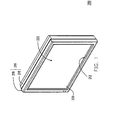
- FIG. 1 is a schematic three-dimensional view of a display apparatus according to an embodiment of the present invention.
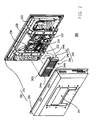
- FIG. 2 is a schematic, partially exploded, three-dimensional view of the display apparatus of FIG. 1 .
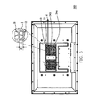
- FIG. 3 is another schematic three-dimensional view of the display apparatus of FIG. 1 .
- FIG. 4 is a schematic exploded three-dimensional view of a dust-proof device of FIG. 2 .
- FIG. 5 is a schematic side view of the display apparatus of FIG. 1 .
- FIG. 6 is a schematic cross-sectional view of the dust-proof device of FIG. 5 taken along a line I-I'.
- FIG. 7 is a schematic three-dimensional view of the dust-proof device of the display apparatus with a dust-proof element replaced according to this embodiment.
- FIG. 1 is a schematic three-dimensional view of a display apparatus according to an embodiment of the present invention
- FIG. 2 is a schematic, partially exploded, three-dimensional view of the display apparatus of FIG. 1
- a display apparatus 200 e.g. a liquid crystal display
- the casing 210 has a first opening 212 and a second opening 214.
- the display module 220 is disposed in the casing 210 and has a display area 222 and a non-display area 224.
- the first opening 212 exposes the display area 222, and the second opening 214 is corresponding to the non-display area 224.
- the casing 210 includes a frame 216 and a cover 218.
- the frame 216 surrounds the display area 222 of the display module 220, such that the first opening 212 formed on the frame 216 exposes the display area 222.
- the cover 218 may be assembled on the frame 216 by means of screws, such that the display module 220 is disposed in the casing 210 and the second opening 214 of the cover 218 is corresponding to the non-display area 224.
- FIG. 3 is another schematic three-dimensional view of the display apparatus of FIG. 1 . It should be explained that for the convenience of illustration, part of the components of display apparatus 200 of FIG. 3 are not depicted (with details described below).
- the cooling devices 230 e.g. axial fans, are disposed at the non-display area 224 in the casing 210. Each cooling device 230 has an air inlet 232 corresponding to the second opening 214 of the casing 210.
- FIG. 4 is a schematic exploded three-dimensional view of the dust-proof device of FIG. 2 .
- the dust-proof device 240 includes a body 242, a cover 244, and a dust-proof element 246 (the dust-proof element 246 is not shown in FIG. 3 ).
- the dust-proof element 246 e.g. a dust-proof sheet
- the body 242 is disposed at the non-display area 224 in the casing 210.
- the body 242 has a plurality of first holes 242a corresponding to the air inlets 232 of the cooling devices 230.
- the body 242 includes a first window frame portion 242b and a ring portion 242c.
- the first holes 242a are formed on the first window frame portion 242b, the first window frame portion 242b is connected to the ring portion242c, and the cooling devices 230 are located in the body 242.
- the cover 244 of the dust-proof device 240 is disposed at the body 242 and has a plurality of second holes 244a.
- the second opening 214 of the casing 210 exposes the second holes 244a.
- the cover 244 includes a second window frame portion 244b and two opposite side boards 244c.
- the second holes 244a are formed on the second window frame portion 244b, and the second window frame portion 244b is connected to the side boards 244c.
- Each side board 244c is slidingly disposed at the ring portion 242c of the body 242.
- each side board 244c of the cover 244 has a slide rail S, and the ring portion 242c of the body 242 has two protrusions P.
- the protrusions P respectively pass through the slide rails S, and two fixing elements 248 (e.g. screws) are respectively fixed in the protrusions P, such that each side board 244c is slidingly disposed at the ring portion 242c of the body 242.
- the second window frame portion 244b is fixed on the first window frame portion 242b through a plurality of additional fixing elements 249 (e.g. screws).
- FIG. 5 is a schematic side view of the display apparatus of FIG. 1 . It should be explained that for the convenience of illustration, the dust-proof element 246 of the display apparatus of FIG. 5 is not shown.
- each second hole 244a overlaps at least one of the first holes 242a.
- the body 242 further has a surface 242d.
- the first holes 242a are formed on the surface 242d, each first hole 242a is a rectangular hole, and each second hole 244a is a rectangular hole.
- the orthogonal projections of the second holes 244a on the surface 242d and the first holes 242a form a plurality of interlaced holes I, and the shortest distance d between the two opposite edges 11 and 12 of each interlaced hole I is smaller than 12 mm.
- FIG. 6 is a schematic cross-sectional view of the dust-proof device of FIG. 5 taken along a line I-I'.
- each cooling device 230 is capable of producing an airflow 234.
- the airflows 234 are capable of dissipating the heat generated by the electronic elements of the display apparatus 200 (as shown in FIG. 2 , but not marked).
- the dust-proof element 246 is disposed between the body 242 and the cover 244, and each airflow 234 flows through the second opening 214, the second holes 244a, the dust-proof element 246, the first holes 242a, and the corresponding air inlet 232 to flow into the interior of the corresponding cooling device 230.
- the display apparatus 200 of this embodiment effectively prevents foreign matters forced by the airflow 234 from flowing into the interior of the display apparatus 200, such that the display apparatus 200 of the embodiment of the present invention complies with the dust-proof requirement of the safety standard.
- each second hole 244a of the cover 244 overlaps at least one of the first holes 242a of the body 242 and the dust-proof element 246 having a thickness t is disposed between the body 242 and the cover 244, the airflows 234 may flow into the interior of the display apparatus 200 along the path perpendicular to the arrangement direction of the second holes 244a and the path inclined to the arrangement direction of the second holes 244a. Therefore, the open ratio of the display apparatus 200 of this embodiment is higher, thus improving the intake air amount of the airflow.
- FIG. 7 is a schematic three-dimensional view of the dust-proof device of the display apparatus with the dust-proof element replaced according to this embodiment.
- the user when the user intends to replace the dust-proof element 246, the user first detaches the fixing elements 249 that fixed the second window frame portion 244b to the first window frame portion 242b. Then, the second window frame portion 244b of the cover 244 of the dust-proof device 240 rotates relative to the body 242 through the side boards 244c, such that the cover 244 is in an open state relative to the body 242. Then, the used dust-proof element 246 is taken out and another dust-proof element (not shown) is placed. Therefore, the manner of replacing the dust-proof element 246 of the dust-proof device 240 of this embodiment is relatively simple.
- the display apparatus of the embodiment of the present invention has one, a part of, or all of the following advantages.
- the dust-proof device has the dust-proof element, so that the display apparatus of the embodiment effectively prevents the foreign matters forced by the airflow from flowing into the interior of the display apparatus and complies with the dust-proof requirement of the safety standard.
- the cover of the dust-proof device is disposed on the body of the dust-proof device.
- Each second hole of the cover overlaps at least one of the first holes of the body.
- the dust-proof element is disposed between the body and the cover. Therefore, the open ratio of the display apparatus of the embodiment of the present invention is higher, thus improving the intake air amount of the airflow.
- the second holes of the cover of the dust-proof device and the first holes form the interlaced holes, and the shortest distance between the two opposite edges of each interlaced hole is smaller than 12 mm. Therefore, the fingers of the user are not capable of reaching the interior of the display apparatus through the interlaced holes at will, such that the display apparatus of this embodiment complies with the requirement of the safety standard that the fingers of the user are prevented from reaching the interior of the display apparatus.
- the dust-proof element of the dust-proof device is replaced by means of detaching the fixing element and then opening the cover, so that the manner of replacing the dust-proof element of the dust-proof device of this embodiment is relatively simple.
- the term "the invention”, “the present invention” or the like does not necessarily limit the claim scope to a specific embodiment, and the reference to particularly preferred exemplary embodiments of the invention does not imply a limitation on the invention, and no such limitation is to be inferred.
- the invention is limited only by the spirit and scope of the appended claims.
- the abstract of the disclosure is provided to comply with the rules requiring an abstract, which will allow a searcher to quickly ascertain the subject matter of the technical disclosure of any patent issued from this disclosure. It is submitted with the understanding that it will not be used to interpret or limit the scope or meaning of the claims. Any advantages and benefits described may not apply to all embodiments of the invention.
Landscapes
- Physics & Mathematics (AREA)
- Thermal Sciences (AREA)
- Engineering & Computer Science (AREA)
- Microelectronics & Electronic Packaging (AREA)
- Devices For Indicating Variable Information By Combining Individual Elements (AREA)
- Cooling Or The Like Of Electrical Apparatus (AREA)
- Liquid Crystal (AREA)
Abstract
A display apparatus includes a casing, a display module, a cooling device, and a dust-proof device. The casing has first and second openings. The display module disposed in the casing has a display area exposed by the first opening and a non-display area corresponding to the second opening. The cooling device disposed at the non-display area in the casing has an air inlet corresponding to the second opening. The dust-proof device includes a body disposed at the non-display area in the casing, a cover disposed at the body, and a dust-proof element disposed therebetween. The body has first holes corresponding to the air inlet. The second opening exposes second holes of the cover. Each second hole overlaps at least one of the first holes. An airflow produced by the cooling device flows through the second opening, the second holes, the dust-proof element, the first holes, and the air inlet.
Description
- This application claims the priority benefit of Taiwan application serial no.
97100189, filed on January 3, 2008 - The present invention generally relates to a display apparatus, in particular, to a display apparatus having a dust-proof device.
- In recent years, with the rapid development of technologies related to the display apparatuses, display performance of the display apparatuses is progressively advanced (e.g. the improvement of the brightness of the display apparatuses), and heat generation rates of electronic elements in the display apparatuses are continuously increased. In order to prevent the electronic elements inside the display apparatuses from overheating which causes temporary or permanent breakdown, the heat dissipation performed to the electronic elements inside the display apparatuses becomes more important.
- As for a display apparatus with high brightness, fans are added inside the display apparatus to enhance the heat dissipation performance of the display apparatus, which is a common heat dissipation manner to perform the forced convection. In the conventional art, a casing of the display apparatus has a plurality of holes at an area corresponding to the fan. However, in order to comply with the safety standard (e.g. including the dust-proof regulation and the prevention of user-initiated attempts to put fingers into the interior of the display apparatus through the holes), sizes of the holes are restricted, such that on the whole, an open ratio of the casing of the display apparatus is lower and accordingly the intake air amount is insufficient.
- In view of the above, researchers devote themselves to finding solutions of modifying the design of the holes of the conventional display apparatus and improving the open ratio so as to increase the intake air amount.
- The present invention is directed to a display apparatus having a higher open ratio and complying with the safety standard.
- An embodiment of the present invention provides a display apparatus which includes a casing, a display module, a cooling device, and a dust-proof device. The casing has a first opening and a second opening. The display module is disposed in the casing and has a display area and a non-display area. The first opening exposes the display area, and the second opening is corresponding to the non-display area. The cooling device is disposed at the non-display area in the casing, and the cooling device has an air inlet corresponding to the second opening, and is capable of producing an airflow
- The dust-proof device includes a body, a cover, and a dust-proof element. The body is disposed at the non-display area in the casing. The body has a plurality of first holes corresponding to the air inlet. The cover is disposed at the body, and has a plurality of second holes. The second opening exposes the second holes, and each second hole overlaps at least one of the first holes. The dust-proof element is disposed between the body and the cover, and the airflow flows through the second opening, the second holes, the dust-proof element, the first holes, and the air inlet to flow into the interior of the cooling device.
- The cover of the dust-proof device is disposed on the body of the dust-proof device, each second hole of the cover overlaps at least one of the first holes of the body and the dust-proof element is disposed between the body and the cover. Therefore, as compared with the conventional art, the display apparatus of the embodiment of the present invention complies with the safety standard, and has a higher open ratio to improve the intake air amount of the airflow.
- Other objectives, features and advantages of the present invention will be further understood from the further technological features disclosed by the embodiments of the present invention wherein there are shown and described preferred embodiments of this invention, simply by way of illustration of modes best suited to carry out the invention.
- The accompanying drawings are included to provide a further understanding of the invention, and are incorporated in and constitute a part of this specification. The drawings illustrate embodiments of the invention and, together with the description, serve to explain the principles of the invention.
-
FIG. 1 is a schematic three-dimensional view of a display apparatus according to an embodiment of the present invention. -
FIG. 2 is a schematic, partially exploded, three-dimensional view of the display apparatus ofFIG. 1 . -
FIG. 3 is another schematic three-dimensional view of the display apparatus ofFIG. 1 . -
FIG. 4 is a schematic exploded three-dimensional view of a dust-proof device ofFIG. 2 . -
FIG. 5 is a schematic side view of the display apparatus ofFIG. 1 . -
FIG. 6 is a schematic cross-sectional view of the dust-proof device ofFIG. 5 taken along a line I-I'. -
FIG. 7 is a schematic three-dimensional view of the dust-proof device of the display apparatus with a dust-proof element replaced according to this embodiment. - In the following detailed description of the preferred embodiments, reference is made to the accompanying drawings which form a part hereof, and in which are shown by way of illustration specific embodiments in which the invention may be practiced. In this regard, directional terminology, such as "top," "bottom," "front," "back," etc., is used with reference to the orientation of the Figure(s) being described. The components of the present invention can be positioned in a number of different orientations. As such, the directional terminology is used for purposes of illustration and is in no way limiting. On the other hand, the drawings are only schematic and the sizes of components may be exaggerated for clarity. It is to be understood that other embodiments may be utilized and structural changes may be made without departing from the scope of the present invention. Also, it is to be understood that the phraseology and terminology used herein are for the purpose of description and should not be regarded as limiting. The use of "including," "comprising," or "having" and variations thereof herein are meant to encompass the items listed thereafter and equivalents thereof as well as additional items. Unless limited otherwise, the terms "connected," "coupled," and "mounted" and variations thereof herein are used broadly and encompass direct and indirect connections, couplings, and mountings. Similarly, the terms "facing," "faces" and variations thereof herein are used broadly and encompass direct and indirect facing, and "adjacent to" and variations thereof herein are used broadly and encompass directly and indirectly "adjacent to". Therefore, the description of "A" component facing "B" component herein may contain the situations that "A" component directly faces "B" component or one or more additional components is between "A" component and "B" component. Also, the description of "A" component "adjacent to" "B" component herein may contain the situations that "A" component is directly "adjacent to" "B" component or one or more additional components are between "A" component and "B" component. Accordingly, the drawings and descriptions will be regarded as illustrative in nature and not as restrictive.
-
FIG. 1 is a schematic three-dimensional view of a display apparatus according to an embodiment of the present invention, andFIG. 2 is a schematic, partially exploded, three-dimensional view of the display apparatus ofFIG. 1 . Referring toFIGs. 1 and2 , a display apparatus 200 (e.g. a liquid crystal display) of this embodiment includes acasing 210, adisplay module 220, at least one cooling device 230 (twocooling devices 230 schematically shown inFIG. 2 ), and a dust-proof device 240. Thecasing 210 has afirst opening 212 and asecond opening 214. Thedisplay module 220 is disposed in thecasing 210 and has adisplay area 222 and anon-display area 224. Thefirst opening 212 exposes thedisplay area 222, and thesecond opening 214 is corresponding to thenon-display area 224. - In this embodiment, the
casing 210 includes aframe 216 and acover 218. Theframe 216 surrounds thedisplay area 222 of thedisplay module 220, such that thefirst opening 212 formed on theframe 216 exposes thedisplay area 222. In addition, thecover 218 may be assembled on theframe 216 by means of screws, such that thedisplay module 220 is disposed in thecasing 210 and thesecond opening 214 of thecover 218 is corresponding to thenon-display area 224. -
FIG. 3 is another schematic three-dimensional view of the display apparatus ofFIG. 1 . It should be explained that for the convenience of illustration, part of the components ofdisplay apparatus 200 ofFIG. 3 are not depicted (with details described below). Referring toFIGs. 2 and3 , the coolingdevices 230, e.g. axial fans, are disposed at thenon-display area 224 in thecasing 210. Eachcooling device 230 has anair inlet 232 corresponding to thesecond opening 214 of thecasing 210. -
FIG. 4 is a schematic exploded three-dimensional view of the dust-proof device ofFIG. 2 . Referring toFIGs. 2 ,3 , and4 , the dust-proof device 240 includes abody 242, acover 244, and a dust-proof element 246 (the dust-proof element 246 is not shown inFIG. 3 ). The dust-proof element 246 (e.g. a dust-proof sheet) is disposed between thebody 242 and thecover 244. Thebody 242 is disposed at thenon-display area 224 in thecasing 210. Thebody 242 has a plurality offirst holes 242a corresponding to theair inlets 232 of thecooling devices 230. In this embodiment, thebody 242 includes a first window frame portion 242b and aring portion 242c. Thefirst holes 242a are formed on the first window frame portion 242b, the first window frame portion 242b is connected to the ring portion242c, and thecooling devices 230 are located in thebody 242. - The
cover 244 of the dust-proof device 240 is disposed at thebody 242 and has a plurality of second holes 244a. Thesecond opening 214 of thecasing 210 exposes the second holes 244a. In this embodiment, thecover 244 includes a secondwindow frame portion 244b and twoopposite side boards 244c. The second holes 244a are formed on the secondwindow frame portion 244b, and the secondwindow frame portion 244b is connected to theside boards 244c. Eachside board 244c is slidingly disposed at thering portion 242c of thebody 242. In detail, eachside board 244c of thecover 244 has a slide rail S, and thering portion 242c of thebody 242 has two protrusions P. The protrusions P respectively pass through the slide rails S, and two fixing elements 248 (e.g. screws) are respectively fixed in the protrusions P, such that eachside board 244c is slidingly disposed at thering portion 242c of thebody 242. In addition, the secondwindow frame portion 244b is fixed on the first window frame portion 242b through a plurality of additional fixing elements 249 (e.g. screws). -
FIG. 5 is a schematic side view of the display apparatus ofFIG. 1 . It should be explained that for the convenience of illustration, the dust-proof element 246 of the display apparatus ofFIG. 5 is not shown. Referring toFIGs. 3 ,4 , and5 , each second hole 244a overlaps at least one of thefirst holes 242a. In detail, thebody 242 further has asurface 242d. Thefirst holes 242a are formed on thesurface 242d, eachfirst hole 242a is a rectangular hole, and each second hole 244a is a rectangular hole. The orthogonal projections of the second holes 244a on thesurface 242d and thefirst holes 242a form a plurality of interlaced holes I, and the shortest distance d between the twoopposite edges display apparatus 200 through the interlaced holes I at will such that thedisplay apparatus 200 of this embodiment complies with the requirement prescribed in the safety standard that the fingers of the user are prevented from reaching the interior of thedisplay apparatus 200. - Hereinafter, the operation processes of the
cooling devices 230 of this embodiment are illustrated.FIG. 6 is a schematic cross-sectional view of the dust-proof device ofFIG. 5 taken along a line I-I'. Referring toFIGs. 3 ,4 , and6 , each coolingdevice 230 is capable of producing anairflow 234. Eachairflow 234, for example, sequentially flows through thesecond opening 214 of the casing (as shown inFIG. 2 ), the second holes 244a of thecover 244 of the dust-proof device 240, the dust-proof elements 246 of the dust-proof device 240, thefirst holes 242a of thebody 242 of the dust-proof device 240, and theair inlet 232 of the corresponding cooling device 230 (as shown inFIG. 2 ) to flow into the interior of thecorresponding cooling device 230. Thus, theairflows 234 are capable of dissipating the heat generated by the electronic elements of the display apparatus 200 (as shown inFIG. 2 , but not marked). - The dust-
proof element 246 is disposed between thebody 242 and thecover 244, and eachairflow 234 flows through thesecond opening 214, the second holes 244a, the dust-proof element 246, thefirst holes 242a, and thecorresponding air inlet 232 to flow into the interior of thecorresponding cooling device 230. Thus, thedisplay apparatus 200 of this embodiment effectively prevents foreign matters forced by theairflow 234 from flowing into the interior of thedisplay apparatus 200, such that thedisplay apparatus 200 of the embodiment of the present invention complies with the dust-proof requirement of the safety standard. Moreover, because thecover 244 of the dust-proof device 240 is disposed on thebody 242 of the dust-proof device 240, each second hole 244a of thecover 244 overlaps at least one of thefirst holes 242a of thebody 242 and the dust-proof element 246 having a thickness t is disposed between thebody 242 and thecover 244, theairflows 234 may flow into the interior of thedisplay apparatus 200 along the path perpendicular to the arrangement direction of the second holes 244a and the path inclined to the arrangement direction of the second holes 244a. Therefore, the open ratio of thedisplay apparatus 200 of this embodiment is higher, thus improving the intake air amount of the airflow. - Hereinafter, the processes of replacing the dust-
proof element 246 of the dust-proof device 240 of this embodiment are illustrated.FIG. 7 is a schematic three-dimensional view of the dust-proof device of the display apparatus with the dust-proof element replaced according to this embodiment. Referring toFIGs. 4 and7 , in this embodiment, when the user intends to replace the dust-proof element 246, the user first detaches the fixingelements 249 that fixed the secondwindow frame portion 244b to the first window frame portion 242b. Then, the secondwindow frame portion 244b of thecover 244 of the dust-proof device 240 rotates relative to thebody 242 through theside boards 244c, such that thecover 244 is in an open state relative to thebody 242. Then, the used dust-proof element 246 is taken out and another dust-proof element (not shown) is placed. Therefore, the manner of replacing the dust-proof element 246 of the dust-proof device 240 of this embodiment is relatively simple. - To sum up, the display apparatus of the embodiment of the present invention has one, a part of, or all of the following advantages.
- 1. The dust-proof device has the dust-proof element, so that the display apparatus of the embodiment effectively prevents the foreign matters forced by the airflow from flowing into the interior of the display apparatus and complies with the dust-proof requirement of the safety standard.
- 2. The cover of the dust-proof device is disposed on the body of the dust-proof device. Each second hole of the cover overlaps at least one of the first holes of the body. The dust-proof element is disposed between the body and the cover. Therefore, the open ratio of the display apparatus of the embodiment of the present invention is higher, thus improving the intake air amount of the airflow.
- 3. The second holes of the cover of the dust-proof device and the first holes form the interlaced holes, and the shortest distance between the two opposite edges of each interlaced hole is smaller than 12 mm. Therefore, the fingers of the user are not capable of reaching the interior of the display apparatus through the interlaced holes at will, such that the display apparatus of this embodiment complies with the requirement of the safety standard that the fingers of the user are prevented from reaching the interior of the display apparatus.
- 4. The dust-proof element of the dust-proof device is replaced by means of detaching the fixing element and then opening the cover, so that the manner of replacing the dust-proof element of the dust-proof device of this embodiment is relatively simple.
- The foregoing description of the preferred embodiments of the invention has been presented for purposes of illustration and description. It is not intended to be exhaustive or to limit the invention to the precise form or to exemplary embodiments disclosed. Accordingly, the foregoing description should be regarded as illustrative rather than restrictive. Obviously, many modifications and variations will be apparent to practitioners skilled in this art. The embodiments are chosen and described in order to best explain the principles of the invention and its best mode practical application, thereby to enable persons skilled in the art to understand the invention for various embodiments and with various modifications as are suited to the particular use or implementation contemplated. It is intended that the scope of the invention be defined by the claims appended hereto and their equivalents in which all terms are meant in their broadest reasonable sense unless otherwise indicated. Therefore, the term "the invention", "the present invention" or the like does not necessarily limit the claim scope to a specific embodiment, and the reference to particularly preferred exemplary embodiments of the invention does not imply a limitation on the invention, and no such limitation is to be inferred. The invention is limited only by the spirit and scope of the appended claims. The abstract of the disclosure is provided to comply with the rules requiring an abstract, which will allow a searcher to quickly ascertain the subject matter of the technical disclosure of any patent issued from this disclosure. It is submitted with the understanding that it will not be used to interpret or limit the scope or meaning of the claims. Any advantages and benefits described may not apply to all embodiments of the invention. It should be appreciated that variations may be made in the embodiments described by persons skilled in the art without departing from the scope of the present invention as defined by the following claims. Moreover, no element and component in the present disclosure is intended to be dedicated to the public regardless of whether the element or component is explicitly recited in the following claims.
Claims (7)
- A display apparatus, comprising:a casing, having a first opening and a second opening;a display module, disposed in the casing and having a display area and a non-display area, wherein the first opening exposes the display area, and the second opening is corresponding to the non-display area;a cooling device, disposed at the non-display area in the casing, wherein the cooling device comprises an air inlet corresponding to the second opening, and the cooling device is capable of producing an airflow; anda dust-proof device, comprising:a body, disposed at the non-display area in the casing, wherein the body comprises a plurality of first holes corresponding to the air inlet;a cover, disposed at the body, wherein the cover has a plurality of second holes, the second opening exposes the second holes, and each second hole overlaps at least one of the first holes; anda dust-proof element, disposed between the body and the cover, wherein the airflow flows through the second opening, the second holes, the dust-proof element, the first holes, and the air inlet to flow into an interior of the cooling device.
- The display apparatus according to claim 1, wherein the body further has a surface, the first holes are formed on the surface, each first hole is a rectangular hole, each second hole is a rectangular hole, orthogonal projections of the second holes on the surface and the first holes form a plurality of interlaced holes, and a shortest distance between two opposite edges of each interlaced hole is smaller than 12 mm.
- The display apparatus according to claim 1, wherein the body comprises a first window frame portion and a ring portion, wherein the first holes are formed at the first window frame portion, the first window frame portion is connected to the ring portion, and the cooling device is located in the body.
- The display apparatus according to claim 3, wherein the cover comprises a second window frame portion and two opposite side boards, the second holes are formed at the second window frame portion, the second window frame portion connects the side boards, each side board is slidingly disposed at the ring portion, and the second window frame portion is capable of rotating relative to the body through the side boards.
- The display apparatus according to claim 4, wherein the dust-proof device further comprises at least one fixing element and the second window frame portion is fixed on the first window frame portion through the fixing element.
- The display apparatus according to claim 5, wherein the fixing element comprises a screw.
- The display apparatus according to claim 1, wherein the cooling device comprises an axial fan.
Applications Claiming Priority (1)
| Application Number | Priority Date | Filing Date | Title |
|---|---|---|---|
| TW097100189A TW200932085A (en) | 2008-01-03 | 2008-01-03 | Display apparatus |
Publications (1)
| Publication Number | Publication Date |
|---|---|
| EP2077706A2 true EP2077706A2 (en) | 2009-07-08 |
Family
ID=40386459
Family Applications (1)
| Application Number | Title | Priority Date | Filing Date |
|---|---|---|---|
| EP08018240A Withdrawn EP2077706A2 (en) | 2008-01-03 | 2008-10-17 | Display apparatus |
Country Status (3)
| Country | Link |
|---|---|
| US (1) | US7580258B2 (en) |
| EP (1) | EP2077706A2 (en) |
| TW (1) | TW200932085A (en) |
Families Citing this family (7)
| Publication number | Priority date | Publication date | Assignee | Title |
|---|---|---|---|---|
| KR101387932B1 (en) * | 2008-05-07 | 2014-04-23 | 삼성전자주식회사 | Display unit and vending maching having the same |
| CN102668546A (en) * | 2009-12-03 | 2012-09-12 | 松下电器产业株式会社 | Radiation unit of electronic device and electronic device using same |
| US9210820B2 (en) * | 2012-02-20 | 2015-12-08 | Asustek Computer Inc. | Electronic device |
| CN103838331A (en) * | 2012-11-23 | 2014-06-04 | 鸿富锦精密工业(深圳)有限公司 | Notebook computer |
| CN105163563B (en) * | 2015-08-27 | 2018-04-17 | 苏州佳世达电通有限公司 | Display device |
| US9756768B2 (en) * | 2015-11-06 | 2017-09-05 | Litemax Electronics Inc. | Heat-dissipating structure mounted on back of display unit |
| TWI623254B (en) * | 2016-03-31 | 2018-05-01 | 揚昇照明股份有限公司 | Electronic device |
Family Cites Families (19)
| Publication number | Priority date | Publication date | Assignee | Title |
|---|---|---|---|---|
| CA1314237C (en) * | 1988-11-01 | 1993-03-09 | William E. Pick | Charging element having odour absorbing properties for an electrostatic air filter |
| US5464461A (en) * | 1993-12-01 | 1995-11-07 | Electronic Cable Specialists, Inc. | Filter for mounting on an avionic line replaceable unit |
| CA2410140A1 (en) * | 2001-10-30 | 2003-04-30 | Joseph A. Lobiondo, Sr. | Electronic air filter assembly |
| TW583529B (en) * | 2001-11-15 | 2004-04-11 | Wistron Corp | Liquid crystal display computer with a removable device frame |
| US6942710B2 (en) * | 2002-03-26 | 2005-09-13 | Albert M. Milano | Duct end filter apparatus |
| US6860916B2 (en) * | 2002-06-14 | 2005-03-01 | 3M Innovative Properties Company | Filter assembly |
| TW542010U (en) * | 2002-10-08 | 2003-07-11 | Coretronic Corp | Dust-proof filter apparatus |
| US6843820B2 (en) * | 2003-03-04 | 2005-01-18 | 3M Innovative Properties Company | Filter assembly |
| US7092248B2 (en) * | 2004-01-28 | 2006-08-15 | Paul Shu | Detachable modular computer |
| TWI262758B (en) * | 2004-05-07 | 2006-09-21 | Coretronic Corp | Ventilation cover structure |
| TWM268599U (en) * | 2004-12-22 | 2005-06-21 | Hannspree Inc | LCD panel with fragrance function |
| KR100649598B1 (en) * | 2004-12-29 | 2006-11-27 | 엘지전자 주식회사 | Heat dissipation structure of plasma display panel television |
| JPWO2006092954A1 (en) * | 2005-02-28 | 2008-08-07 | 松下電器産業株式会社 | Flat panel display |
| TW200642577A (en) * | 2005-05-24 | 2006-12-01 | Coretronic Corp | Fixture of the air-venting layer for venting inlet, and its assembly method |
| US20060290812A1 (en) * | 2005-06-22 | 2006-12-28 | First International Computer, Inc. | All in one media center |
| JP2007086444A (en) * | 2005-09-22 | 2007-04-05 | Orion Denki Kk | Display device |
| KR100772247B1 (en) * | 2005-11-04 | 2007-11-01 | 엘지전자 주식회사 | Chillers for Flat Panel Display Devices and Flat Panel Display Devices |
| KR101183457B1 (en) * | 2006-10-16 | 2012-09-14 | 삼성전자주식회사 | Liquid Crystal Display And Control Method Thereof |
| JP4273357B2 (en) * | 2007-03-06 | 2009-06-03 | 船井電機株式会社 | Cooling fan mounting structure for thin display device and plasma television |
-
2008
- 2008-01-03 TW TW097100189A patent/TW200932085A/en unknown
- 2008-04-27 US US12/110,337 patent/US7580258B2/en active Active
- 2008-10-17 EP EP08018240A patent/EP2077706A2/en not_active Withdrawn
Also Published As
| Publication number | Publication date |
|---|---|
| US20090175002A1 (en) | 2009-07-09 |
| US7580258B2 (en) | 2009-08-25 |
| TW200932085A (en) | 2009-07-16 |
Similar Documents
| Publication | Publication Date | Title |
|---|---|---|
| US7580258B2 (en) | Display apparatus | |
| US20200253095A1 (en) | Dual electronic display assembly | |
| CN105974662B (en) | display device | |
| EP2106206B1 (en) | Cooling device for accomodated printed circuit board in a chassis | |
| EP1784069B1 (en) | Cooling apparatus for flat display device | |
| US20110122162A1 (en) | Display apparatus | |
| EP2508759A2 (en) | Cooling system equipped with an advection-type fan | |
| KR100772247B1 (en) | Chillers for Flat Panel Display Devices and Flat Panel Display Devices | |
| CN102300421A (en) | Electronic device shell | |
| JP2007149007A (en) | Electronics | |
| US8760862B2 (en) | Heat dissipating device and portable electronic device using the same | |
| US7177150B2 (en) | Adjustable flat-type cooling device | |
| EP1903419A1 (en) | Printed circuit board unit having void for receiving fan | |
| US20100214738A1 (en) | Portable electronic device and dissipating structure thereof | |
| US20090059514A1 (en) | Heat dissipating apparatus of computer | |
| KR101359740B1 (en) | Computer case | |
| CN105785620A (en) | Display device with fan | |
| WO2011011909A1 (en) | Integrative computer and its mainframe case | |
| JP2011053258A (en) | Plasma display device | |
| US8235560B2 (en) | Backlight module | |
| CN201312468Y (en) | Heat abstractor for display | |
| CN101528020A (en) | Display device | |
| JP5039009B2 (en) | Display device | |
| US20110211171A1 (en) | Light source apparatus and projection device | |
| JP4897107B2 (en) | Electronics |
Legal Events
| Date | Code | Title | Description |
|---|---|---|---|
| PUAI | Public reference made under article 153(3) epc to a published international application that has entered the european phase |
Free format text: ORIGINAL CODE: 0009012 |
|
| AK | Designated contracting states |
Kind code of ref document: A2 Designated state(s): AT BE BG CH CY CZ DE DK EE ES FI FR GB GR HR HU IE IS IT LI LT LU LV MC MT NL NO PL PT RO SE SI SK TR |
|
| AX | Request for extension of the european patent |
Extension state: AL BA MK RS |
|
| STAA | Information on the status of an ep patent application or granted ep patent |
Free format text: STATUS: THE APPLICATION IS DEEMED TO BE WITHDRAWN |
|
| 18D | Application deemed to be withdrawn |
Effective date: 20110503 |