EP2077477A2 - Failsafe remote data concentrator - Google Patents
Failsafe remote data concentrator Download PDFInfo
- Publication number
- EP2077477A2 EP2077477A2 EP08254190A EP08254190A EP2077477A2 EP 2077477 A2 EP2077477 A2 EP 2077477A2 EP 08254190 A EP08254190 A EP 08254190A EP 08254190 A EP08254190 A EP 08254190A EP 2077477 A2 EP2077477 A2 EP 2077477A2
- Authority
- EP
- European Patent Office
- Prior art keywords
- sensors
- signal processing
- remote data
- signals
- data concentrator
- Prior art date
- Legal status (The legal status is an assumption and is not a legal conclusion. Google has not performed a legal analysis and makes no representation as to the accuracy of the status listed.)
- Granted
Links
Images

Classifications
-
- G—PHYSICS
- G05—CONTROLLING; REGULATING
- G05D—SYSTEMS FOR CONTROLLING OR REGULATING NON-ELECTRIC VARIABLES
- G05D1/00—Control of position, course, altitude or attitude of land, water, air or space vehicles, e.g. using automatic pilots
- G05D1/0055—Control of position, course, altitude or attitude of land, water, air or space vehicles, e.g. using automatic pilots with safety arrangements
- G05D1/0077—Control of position, course, altitude or attitude of land, water, air or space vehicles, e.g. using automatic pilots with safety arrangements using redundant signals or controls
-
- G—PHYSICS
- G06—COMPUTING OR CALCULATING; COUNTING
- G06F—ELECTRIC DIGITAL DATA PROCESSING
- G06F11/00—Error detection; Error correction; Monitoring
- G06F11/07—Responding to the occurrence of a fault, e.g. fault tolerance
- G06F11/16—Error detection or correction of the data by redundancy in hardware
- G06F11/20—Error detection or correction of the data by redundancy in hardware using active fault-masking, e.g. by switching out faulty elements or by switching in spare elements
- G06F11/2002—Error detection or correction of the data by redundancy in hardware using active fault-masking, e.g. by switching out faulty elements or by switching in spare elements where interconnections or communication control functionality are redundant
- G06F11/2007—Error detection or correction of the data by redundancy in hardware using active fault-masking, e.g. by switching out faulty elements or by switching in spare elements where interconnections or communication control functionality are redundant using redundant communication media
-
- G—PHYSICS
- G06—COMPUTING OR CALCULATING; COUNTING
- G06F—ELECTRIC DIGITAL DATA PROCESSING
- G06F11/00—Error detection; Error correction; Monitoring
- G06F11/07—Responding to the occurrence of a fault, e.g. fault tolerance
- G06F11/16—Error detection or correction of the data by redundancy in hardware
- G06F11/20—Error detection or correction of the data by redundancy in hardware using active fault-masking, e.g. by switching out faulty elements or by switching in spare elements
- G06F11/202—Error detection or correction of the data by redundancy in hardware using active fault-masking, e.g. by switching out faulty elements or by switching in spare elements where processing functionality is redundant
- G06F11/2035—Error detection or correction of the data by redundancy in hardware using active fault-masking, e.g. by switching out faulty elements or by switching in spare elements where processing functionality is redundant without idle spare hardware
-
- H—ELECTRICITY
- H04—ELECTRIC COMMUNICATION TECHNIQUE
- H04Q—SELECTING
- H04Q9/00—Arrangements in telecontrol or telemetry systems for selectively calling a substation from a main station, in which substation desired apparatus is selected for applying a control signal thereto or for obtaining measured values therefrom
-
- G—PHYSICS
- G08—SIGNALLING
- G08C—TRANSMISSION SYSTEMS FOR MEASURED VALUES, CONTROL OR SIMILAR SIGNALS
- G08C2201/00—Transmission systems of control signals via wireless link
- G08C2201/60—Security, fault tolerance
- G08C2201/63—Redundant transmissions
-
- H—ELECTRICITY
- H04—ELECTRIC COMMUNICATION TECHNIQUE
- H04Q—SELECTING
- H04Q2209/00—Arrangements in telecontrol or telemetry systems
- H04Q2209/20—Arrangements in telecontrol or telemetry systems using a distributed architecture
Definitions
- This application relates to a remote data concentrator.
- Sensors may sense the position of a switch, temperature, pressure, proximity, etc. Such sensors are located throughout an aircraft.
- RDCs remote data concentrators
- a serial communication bus is used to route the information from the RDCs to downstream equipment.
- RDCs have failure modes that could result in the loss of a large quantity of input data. This may lead to loss of a control function, which is undesirable.
- signals either going to or from an RDC are provided along redundant streams such that the loss of one or some of the streams will not mean all sensor information will be lost.
- the RDC includes plural digital signal processing controllers.
- FIG. 1 An aircraft 10 is illustrated in Figure 1 .
- a plurality of sensors S each communicate through an RDC with the rest of the aircraft.
- the RDCs may communicate forwardly to the flight deck 11 or other controller.
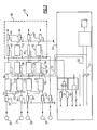
- RDC 20 is illustrated in Figure 2 .
- a plurality of sensors 22, 24, 26, and 28 communicate downstream through filters 30.
- each of the sensor signals are split between lines 31 and 33.
- each of the two signals pass through a distinct input conditioning box 32, and travel to two signal processing controllers 36.
- the sensor information will not be lost.
- the sensors are provided in pairs and each of the sensors is a pair, for example 22 and 24 or 26 and 28, communicate with the same two signal processing controllers 36.
- a box 38 Downstream of the signal processing controllers is a box 38 which provides output processing of signals, and includes ground/opening signals 40, and output conditioning 42, along with filters 44. This portion of the RDC 20 is as known in the art.
- a pair of lines 50 & 52 are connected at 48 & 46 to each of the signal processing controllers 36, and extend downstream to a module control interface 54. Thus, should either of the lines 50 or 52 fail, the overall signal will still pass from or to an appropriate controller.
- information from a sensor leading to a signal processing controller is split such that failure of any one signal processing controller will not cause loss of sensor information.
- the information downstream of the signal processing controller is provided on two lines such that the loss of either line will not cause loss of all sensor information.
Landscapes
- Engineering & Computer Science (AREA)
- Theoretical Computer Science (AREA)
- Physics & Mathematics (AREA)
- General Physics & Mathematics (AREA)
- Quality & Reliability (AREA)
- General Engineering & Computer Science (AREA)
- Aviation & Aerospace Engineering (AREA)
- Radar, Positioning & Navigation (AREA)
- Remote Sensing (AREA)
- Automation & Control Theory (AREA)
- Computer Networks & Wireless Communication (AREA)
- Arrangements For Transmission Of Measured Signals (AREA)
- Selective Calling Equipment (AREA)
- Small-Scale Networks (AREA)
Abstract
Description
- This application relates to a remote data concentrator.
- Sensors, and in particular in aircraft, may sense the position of a switch, temperature, pressure, proximity, etc. Such sensors are located throughout an aircraft.
- In the past, hard wiring has been used to connect each of these sensors to various controllers, or to the flight deck. Of course, this resulted in large amounts of wire.
- Recently, aircraft have been provided with remote data concentrators (RDCs) to be mounted throughout the aircraft to collect the sensor data. A serial communication bus is used to route the information from the RDCs to downstream equipment.
- Some of these RDCs have failure modes that could result in the loss of a large quantity of input data. This may lead to loss of a control function, which is undesirable.
- In a disclosed embodiment of this invention, signals either going to or from an RDC are provided along redundant streams such that the loss of one or some of the streams will not mean all sensor information will be lost. In a disclosed embodiment, the RDC includes plural digital signal processing controllers.
- These and other features of the present invention can be best understood from the following specification and drawings, the following of which is a brief description.
-
-
Figure 1 is a schematic view showing an aircraft including a plurality of sensors. -
Figure 2 is a schematic view of a remote data concentrator for the aircraft ofFigure 1 . - An
aircraft 10 is illustrated inFigure 1 . A plurality of sensors S each communicate through an RDC with the rest of the aircraft. The RDCs may communicate forwardly to theflight deck 11 or other controller. - One
RDC 20 is illustrated inFigure 2 . As shown, a plurality ofsensors filters 30. As can be appreciated, downstream of each of thefilters 30, each of the sensor signals are split betweenlines input conditioning box 32, and travel to twosignal processing controllers 36. Thus, should any one of thesignal processing controllers 36 fail, the sensor information will not be lost. - The sensors are provided in pairs and each of the sensors is a pair, for example 22 and 24 or 26 and 28, communicate with the same two
signal processing controllers 36. - Downstream of the signal processing controllers is a
box 38 which provides output processing of signals, and includes ground/opening signals 40, andoutput conditioning 42, along withfilters 44. This portion of the RDC 20 is as known in the art. - In addition, a pair of
lines 50 & 52 are connected at 48 & 46 to each of thesignal processing controllers 36, and extend downstream to amodule control interface 54. Thus, should either of thelines - In sum, information from a sensor leading to a signal processing controller is split such that failure of any one signal processing controller will not cause loss of sensor information. Similarly, the information downstream of the signal processing controller is provided on two lines such that the loss of either line will not cause loss of all sensor information.
- Although an embodiment of this invention has been disclosed, a worker of ordinary skill in this art would recognize that certain modifications would come within the scope of this invention. For that reason, the following claims should be studied to determine the true scope and content of this invention.
Claims (6)
- A remote data concentrator system comprising:a plurality of sensors (22,24,26,28), each of said plurality of sensors delivering sensor signals downstream through at least two signal streams.
- The remote data concentrator system as set forth in claim 1, wherein there is a plurality of signal processing controllers (36), a plurality of sensors having their signals split to be delivered to at least two of said signal processing controllers.
- The remote data concentrator system as set forth in claim 2, wherein said sensors are provided in pairs (22,24;26,28), and each of said sensors within a pair communicate with the same two signal processing controllers (36).
- The remote data concentrator system as set forth in claim 2 or 3, wherein signals pass downstream from said signal processing controller to a module control interface (54) and signals being sent from said module control interface being provided on two lines (50,52) to provide redundancy.
- The remote data concentrator system as set forth in claim 2, 3 or 4 wherein said signals from said sensors pass through a filter (30), and then are split before passing into an input conditioning box (32), and then being delivered to said signal processing controllers (36).
- An airplane electrical control system comprising:a plurality of sensors (22,24,26,28), said plurality of sensors communicating with a common remote data concentrator;a plurality of signal processing controllers (36) in each of said remote data concentrators, said plurality of sensors each having their signals split to be delivered to at least two of said signal processing controllers;said sensors being provided in pairs (22,24;26,28)" and each said sensor within a pair communicating with the same two signal processing controllers (36);signals passing downstream from said signal processing controllers to a module control interface (54); andsignals from said module control interface being provided on two lines (50,52) to provide redundancy.
Applications Claiming Priority (1)
| Application Number | Priority Date | Filing Date | Title |
|---|---|---|---|
| US11/968,765 US7844371B2 (en) | 2008-01-03 | 2008-01-03 | Failsafe remote data concentrator |
Publications (3)
| Publication Number | Publication Date |
|---|---|
| EP2077477A2 true EP2077477A2 (en) | 2009-07-08 |
| EP2077477A3 EP2077477A3 (en) | 2012-10-24 |
| EP2077477B1 EP2077477B1 (en) | 2017-07-19 |
Family
ID=40602425
Family Applications (1)
| Application Number | Title | Priority Date | Filing Date |
|---|---|---|---|
| EP08254190.5A Ceased EP2077477B1 (en) | 2008-01-03 | 2008-12-30 | Failsafe remote data concentrator |
Country Status (2)
| Country | Link |
|---|---|
| US (1) | US7844371B2 (en) |
| EP (1) | EP2077477B1 (en) |
Cited By (1)
| Publication number | Priority date | Publication date | Assignee | Title |
|---|---|---|---|---|
| EP2644506A3 (en) * | 2012-03-26 | 2014-01-22 | Hamilton Sundstrand Corporation | Distributed electronic engine control architecture |
Families Citing this family (1)
| Publication number | Priority date | Publication date | Assignee | Title |
|---|---|---|---|---|
| FR2986398B1 (en) * | 2012-01-30 | 2014-03-07 | Snecma | SAFETY DEVICE FOR CONTROLLING AN ENGINE COMPRISING A REDUNDANCY OF ACQUISITIONS OF A SENSOR MEASUREMENT |
Citations (1)
| Publication number | Priority date | Publication date | Assignee | Title |
|---|---|---|---|---|
| US20060062143A1 (en) | 2004-09-22 | 2006-03-23 | Dave Bibby | Dual lane connection to dual redundant avionics networks |
Family Cites Families (16)
| Publication number | Priority date | Publication date | Assignee | Title |
|---|---|---|---|---|
| US3882406A (en) * | 1973-11-14 | 1975-05-06 | Honeywell Inc | Fault suppressing signal selection apparatus |
| GB1514582A (en) * | 1975-07-15 | 1978-06-14 | Secr Defence | Motion sensor assemblies |
| US4101958A (en) * | 1977-09-01 | 1978-07-18 | Rockwell International Corporation | Apparatus and method for effecting redundant control data transfer in a digital flight control system |
| US4197427A (en) | 1977-11-11 | 1980-04-08 | Lynch Communication Systems, Inc. | Dual-processor line concentrator switching system |
| US4706017A (en) | 1985-08-05 | 1987-11-10 | Hamilton Standard Controls, Inc. | Electrical current sensor |
| US4947116A (en) | 1988-09-02 | 1990-08-07 | Hamilton Standard Controls, Inc. | Inductive speed sensor employing phase shift |
| CA2656141C (en) * | 1998-05-15 | 2012-02-07 | International Road Dynamics Inc. | Method for automatically controlling traffic signalling device |
| US5965819A (en) | 1998-07-06 | 1999-10-12 | Csi Technology | Parallel processing in a vibration analyzer |
| US6272552B1 (en) | 1998-09-24 | 2001-08-07 | Hewlett-Packard Company | Dual channel 100Base-T link for computer networks |
| US6253064B1 (en) * | 1999-02-25 | 2001-06-26 | David A. Monroe | Terminal based traffic management and security surveillance system for aircraft and other commercial vehicles |
| CA2343435C (en) * | 2001-04-06 | 2006-12-05 | International Road Dynamics Inc. | Dynamic work zone safety system |
| US6965840B2 (en) | 2001-07-09 | 2005-11-15 | Sis-Tech Applications, L.P. | Dual sensor process temperature switch having a high-diagnostic one-out-of-two voting architecture |
| US7233876B2 (en) * | 2003-12-05 | 2007-06-19 | Steris Inc. | Data acquisition system providing dual monitoring of sensor data |
| US7215252B2 (en) | 2004-06-16 | 2007-05-08 | Hamilton Sundstrand Corporation | Proximity sensor |
| US7280935B2 (en) | 2004-09-02 | 2007-10-09 | Imation Corp. | Dual sensor assemblies for positional output feedback |
| US7263905B2 (en) | 2005-01-28 | 2007-09-04 | Hamilton Sundstrand Corporation | Removable Hall-Effect sensor system for stator windings in a rotating electric machine |
-
2008
- 2008-01-03 US US11/968,765 patent/US7844371B2/en not_active Expired - Fee Related
- 2008-12-30 EP EP08254190.5A patent/EP2077477B1/en not_active Ceased
Patent Citations (1)
| Publication number | Priority date | Publication date | Assignee | Title |
|---|---|---|---|---|
| US20060062143A1 (en) | 2004-09-22 | 2006-03-23 | Dave Bibby | Dual lane connection to dual redundant avionics networks |
Cited By (1)
| Publication number | Priority date | Publication date | Assignee | Title |
|---|---|---|---|---|
| EP2644506A3 (en) * | 2012-03-26 | 2014-01-22 | Hamilton Sundstrand Corporation | Distributed electronic engine control architecture |
Also Published As
| Publication number | Publication date |
|---|---|
| US7844371B2 (en) | 2010-11-30 |
| US20090177338A1 (en) | 2009-07-09 |
| EP2077477B1 (en) | 2017-07-19 |
| EP2077477A3 (en) | 2012-10-24 |
Similar Documents
| Publication | Publication Date | Title |
|---|---|---|
| US9838436B2 (en) | Aircraft data networks | |
| JP5607919B2 (en) | Integrated airborne electronic system | |
| US10065583B2 (en) | Integrated power distribution, data network, and control architectures for a vehicle | |
| US9387935B2 (en) | Aircraft power distribution network | |
| CN102414081B (en) | Aircraft control system with integrated modular architecture | |
| US10073466B2 (en) | Dual-redundancy flight control system | |
| CN101808900B (en) | Structure distributed between FADEC and avionics components | |
| EP3254960A1 (en) | Electrical architecture for slat/flap control using smart sensors and effectors | |
| CN102421667B (en) | Distributed flight control system implemented according to an integrated modular avionics architecture | |
| US20150073624A1 (en) | Flight control system for unmanned aerial vehicle | |
| US8396612B2 (en) | Avionic system and architecture with integrated power management | |
| US7505400B2 (en) | Dual lane connection to dual redundant avionics networks | |
| US8805600B2 (en) | Flight control system and aircraft comprising it | |
| US20060100750A1 (en) | Dual/triplex flight control architecture | |
| US11099936B2 (en) | Aircraft integrated multi system electronic architecture | |
| CN204883226U (en) | Twin bus avionics system configuration | |
| CN112051859A (en) | An Avionics System of Air Traffic Aircraft Based on AFDX Network | |
| US7844371B2 (en) | Failsafe remote data concentrator | |
| CN105334845B (en) | Mechanical dual-redundancy electrical four-redundancy angle-of-attack redundancy management method | |
| CN106027212B (en) | Communication network, communication device on board aircraft and aircraft including communication device | |
| US8370004B2 (en) | Control panel for an aircraft | |
| US20140156120A1 (en) | Monitoring and failover operation within locomotive distributed control system | |
| CN202126902U (en) | Resistance device with adjustable digital quantity | |
| CN101208936B (en) | Fault Tolerant Data Transmission System in Airliner | |
| CN205121292U (en) | Unmanned aerial vehicle's safe control system |
Legal Events
| Date | Code | Title | Description |
|---|---|---|---|
| PUAI | Public reference made under article 153(3) epc to a published international application that has entered the european phase |
Free format text: ORIGINAL CODE: 0009012 |
|
| AK | Designated contracting states |
Kind code of ref document: A2 Designated state(s): AT BE BG CH CY CZ DE DK EE ES FI FR GB GR HR HU IE IS IT LI LT LU LV MC MT NL NO PL PT RO SE SI SK TR |
|
| AX | Request for extension of the european patent |
Extension state: AL BA MK RS |
|
| REG | Reference to a national code |
Ref country code: DE Ref legal event code: R079 Free format text: PREVIOUS MAIN CLASS: G05D0001000000 Ipc: H04Q0009000000 |
|
| PUAL | Search report despatched |
Free format text: ORIGINAL CODE: 0009013 |
|
| AK | Designated contracting states |
Kind code of ref document: A3 Designated state(s): AT BE BG CH CY CZ DE DK EE ES FI FR GB GR HR HU IE IS IT LI LT LU LV MC MT NL NO PL PT RO SE SI SK TR |
|
| AX | Request for extension of the european patent |
Extension state: AL BA MK RS |
|
| RIC1 | Information provided on ipc code assigned before grant |
Ipc: H04Q 9/00 20060101AFI20120919BHEP Ipc: G05D 1/00 20060101ALI20120919BHEP Ipc: G06F 11/20 20060101ALI20120919BHEP |
|
| 17P | Request for examination filed |
Effective date: 20130409 |
|
| AKX | Designation fees paid |
Designated state(s): FR GB |
|
| REG | Reference to a national code |
Ref country code: DE Ref legal event code: R108 |
|
| REG | Reference to a national code |
Ref country code: DE Ref legal event code: R108 Effective date: 20130703 |
|
| GRAP | Despatch of communication of intention to grant a patent |
Free format text: ORIGINAL CODE: EPIDOSNIGR1 |
|
| INTG | Intention to grant announced |
Effective date: 20170224 |
|
| GRAS | Grant fee paid |
Free format text: ORIGINAL CODE: EPIDOSNIGR3 |
|
| GRAA | (expected) grant |
Free format text: ORIGINAL CODE: 0009210 |
|
| AK | Designated contracting states |
Kind code of ref document: B1 Designated state(s): FR GB |
|
| REG | Reference to a national code |
Ref country code: GB Ref legal event code: FG4D |
|
| REG | Reference to a national code |
Ref country code: FR Ref legal event code: PLFP Year of fee payment: 10 |
|
| PLBE | No opposition filed within time limit |
Free format text: ORIGINAL CODE: 0009261 |
|
| STAA | Information on the status of an ep patent application or granted ep patent |
Free format text: STATUS: NO OPPOSITION FILED WITHIN TIME LIMIT |
|
| 26N | No opposition filed |
Effective date: 20180420 |
|
| PGFP | Annual fee paid to national office [announced via postgrant information from national office to epo] |
Ref country code: FR Payment date: 20201120 Year of fee payment: 13 Ref country code: GB Payment date: 20201123 Year of fee payment: 13 |
|
| GBPC | Gb: european patent ceased through non-payment of renewal fee |
Effective date: 20211230 |
|
| PG25 | Lapsed in a contracting state [announced via postgrant information from national office to epo] |
Ref country code: GB Free format text: LAPSE BECAUSE OF NON-PAYMENT OF DUE FEES Effective date: 20211230 |
|
| PG25 | Lapsed in a contracting state [announced via postgrant information from national office to epo] |
Ref country code: FR Free format text: LAPSE BECAUSE OF NON-PAYMENT OF DUE FEES Effective date: 20211231 |