EP2077456A2 - Ultrasound system and method of providing ultrasound images - Google Patents
Ultrasound system and method of providing ultrasound images Download PDFInfo
- Publication number
- EP2077456A2 EP2077456A2 EP08022094A EP08022094A EP2077456A2 EP 2077456 A2 EP2077456 A2 EP 2077456A2 EP 08022094 A EP08022094 A EP 08022094A EP 08022094 A EP08022094 A EP 08022094A EP 2077456 A2 EP2077456 A2 EP 2077456A2
- Authority
- EP
- European Patent Office
- Prior art keywords
- gap
- mode image
- edge points
- ultrasound
- image
- Prior art date
- Legal status (The legal status is an assumption and is not a legal conclusion. Google has not performed a legal analysis and makes no representation as to the accuracy of the status listed.)
- Granted
Links
Images




Classifications
-
- A—HUMAN NECESSITIES
- A61—MEDICAL OR VETERINARY SCIENCE; HYGIENE
- A61B—DIAGNOSIS; SURGERY; IDENTIFICATION
- A61B8/00—Diagnosis using ultrasonic, sonic or infrasonic waves
-
- G—PHYSICS
- G01—MEASURING; TESTING
- G01S—RADIO DIRECTION-FINDING; RADIO NAVIGATION; DETERMINING DISTANCE OR VELOCITY BY USE OF RADIO WAVES; LOCATING OR PRESENCE-DETECTING BY USE OF THE REFLECTION OR RERADIATION OF RADIO WAVES; ANALOGOUS ARRANGEMENTS USING OTHER WAVES
- G01S15/00—Systems using the reflection or reradiation of acoustic waves, e.g. sonar systems
- G01S15/88—Sonar systems specially adapted for specific applications
- G01S15/89—Sonar systems specially adapted for specific applications for mapping or imaging
- G01S15/8906—Short-range imaging systems; Acoustic microscope systems using pulse-echo techniques
- G01S15/8979—Combined Doppler and pulse-echo imaging systems
-
- G—PHYSICS
- G01—MEASURING; TESTING
- G01S—RADIO DIRECTION-FINDING; RADIO NAVIGATION; DETERMINING DISTANCE OR VELOCITY BY USE OF RADIO WAVES; LOCATING OR PRESENCE-DETECTING BY USE OF THE REFLECTION OR RERADIATION OF RADIO WAVES; ANALOGOUS ARRANGEMENTS USING OTHER WAVES
- G01S7/00—Details of systems according to groups G01S13/00, G01S15/00, G01S17/00
- G01S7/52—Details of systems according to groups G01S13/00, G01S15/00, G01S17/00 of systems according to group G01S15/00
- G01S7/52017—Details of systems according to groups G01S13/00, G01S15/00, G01S17/00 of systems according to group G01S15/00 particularly adapted to short-range imaging
- G01S7/52023—Details of receivers
- G01S7/52034—Data rate converters
-
- G—PHYSICS
- G01—MEASURING; TESTING
- G01S—RADIO DIRECTION-FINDING; RADIO NAVIGATION; DETERMINING DISTANCE OR VELOCITY BY USE OF RADIO WAVES; LOCATING OR PRESENCE-DETECTING BY USE OF THE REFLECTION OR RERADIATION OF RADIO WAVES; ANALOGOUS ARRANGEMENTS USING OTHER WAVES
- G01S7/00—Details of systems according to groups G01S13/00, G01S15/00, G01S17/00
- G01S7/52—Details of systems according to groups G01S13/00, G01S15/00, G01S17/00 of systems according to group G01S15/00
- G01S7/52017—Details of systems according to groups G01S13/00, G01S15/00, G01S17/00 of systems according to group G01S15/00 particularly adapted to short-range imaging
- G01S7/52085—Details related to the ultrasound signal acquisition, e.g. scan sequences
Definitions
- the present invention generally relates to ultrasound systems, and more particularly to an ultrasound system and a method of providing ultrasound images in a duplex mode.
- An ultrasound system has become an important and popular diagnostic tool due to its non-invasive and non-destructive nature.
- Modem high-performance ultrasound imaging diagnostic devices and techniques are commonly used to produce two- or three-dimensional images of internal features of patients.
- the ultrasound system operates in a duplex mode for simultaneously providing ultrasound images in two or more diagnostic modes.
- the ultrasound system may provide a BD-mode image with a blood flow or movement of a target object indicated.
- the BD-mode is a diagnostic mode for providing a brightness (B)-mode image and a Doppler (D)-mode image at the same time.
- the D-mode image may include a spectral Doppler image formed based on Doppler signals, which are obtained from a sample volume set on the B-mode image.
- the D-mode image may indicate information regarding the moving direction and velocity of a blood flow or moving object.
- a horizontal axis may represent time while a vertical axis represents velocity (or frequency).
- the ultrasound system may alternately transmit a first ultrasound beam for obtaining the B-mode image and a second ultrasound beam for obtaining the D-mode image.
- the second ultrasound beam may not be transmitted while the first ultrasound beam is transmitted in the BD-mode.
- a pulse repetition frequency (PRF) for the second ultrasound pulse may increase.
- PRF pulse repetition frequency
- a velocity scale in the spectral Doppler image may be lowered so that a detectable maximum velocity of a blood flow may be decreased.
- the first ultrasound beam may be transmitted for a first predetermined time duration.
- the second ultrasound pulse may be transmitted for a second predetermined time duration. In such a case, however, the second ultrasound beam may not be transmitted for the first predetermined time duration for transmitting the first ultrasound beam.
- a gap corresponding to the first predetermined time duration may occur in the D-mode image.
- FIG. 1 is a block diagram showing an ultrasound system in accordance with one embodiment of the present invention.
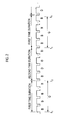
- FIG. 2 is a timing diagram showing an example of alternately transmitting a first ultrasound beam and a second ultrasound beam in a duplex mode.
- FIG. 3 is a block diagram showing a D-mode image processing unit in accordance with one embodiment of the present invention.
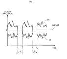
- FIG. 4 is a schematic diagram showing an example of a D-mode image.
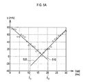
- FIG. 5A is a graph showing examples of first degree polynomial curves.
- FIG. 5B is a graph showing an example of a second degree polynomial curve.
- FIG. 6 is a schematic diagram illustrating an example of gap filling.
- FIG. 1 is a block diagram showing an ultrasound system in accordance with one embodiment of the present invention.
- the ultrasound system 100 may include a user input unit 110 allowing a user to input instructions.
- the instructions may include a setup instruction for setting a sample volume on a B-mode image.
- the setup instruction may include information about the position and size of the sample volume.
- the input unit 110 may be an arbitrary input device such as a mouse, a keyboard, a track ball, etc.
- the ultrasound system 100 may further include a transmission/reception unit 120 configured to generate ultrasound beams.
- the ultrasound beams may be transmitted to a target object.
- the transmission/reception unit 120 may be further configured to convert ultrasound echoes reflected from a target object into electrical receive signals.
- the ultrasound system 100 may further include a control unit 110 configured to generate control signals for controlling the generation of ultrasound beams in the transmission/reception unit 110.
- the control signals may include a first control signal for controlling the generation of an ultrasound beam for obtaining a B-mode image ("first ultrasound beam”).
- the control signals may further include a second control signal for controlling the generation of an ultrasound beam for obtaining a D-mode image ("second ultrasound beam”).
- the second control signal may be generated based on the setup instruction inputted through the user input unit 110.
- the first ultrasound beam is transmitted for obtaining the B-mode image in one embodiment, the obtainable image is not limited to the B-mode image.
- a motion mode image or a color mode image may be obtained based on the first ultrasound beam.
- the control unit 130 may generate the control signals such that the first ultrasound beam is transmitted for a predetermined time duration ("first time duration”) and the second ultrasound beam is transmitted for a predetermined time duration ("second time duration”), as illustrated in FIG. 2 .
- first time duration a predetermined time duration
- second time duration a predetermined time duration
- a symbol "G" in FIG. 2 may represent a gap corresponding to the first time duration t 1 -t 2 or t 3 -t 4 in the D-mode image.
- the transmission/reception unit 110 may be configured to transmit the first ultrasound beam to the target object in response to the first control signal and form receive signals based on ultrasound echoes reflected from the target object. Also, the transmission/reception unit 110 may transmit the second ultrasound beam to the sample volume in response to the second control signal and form spectral Doppler signals based on ultrasound echoes reflected from the sample volume.
- the ultrasound system 100 may further include an image processing unit 140.
- the image processing unit 140 may include a B-mode image processing unit 142 and a D-mode image processing unit 144.
- the B-mode image processing unit 142 may be configured to form a B-mode image based on the receive signals.
- the D-mode image processing unit 144 may form a D-mode image (i.e., spectral Doppler image) based on the spectral Doppler signals.
- the D-mode image processing unit 144 may be further configured to extract edge points from the D-mode image and estimate edge points at a gap corresponding to the first time duration in the D-mode image.
- the D-mode image processing unit 144 may perform gap filling for the gap based on the estimated edge points.
- FIG. 3 is a block diagram showing an embodiment of the D-mode image processing unit 144.
- the D-mode image processing unit 144 may include a D-mode image forming unit 144a, an edge point extracting unit 144b, an edge point estimating unit 144c and a gap filling unit 144d.
- the D-mode image forming unit 144a may be configured to form a D-mode image containing gaps G occurring when transmitting the first ultrasound beam for the first time duration, as illustrated in FIG. 4 .
- a horizontal axis may represent time and a vertical axis may represent velocity (or frequency).
- the edge point extracting unit 144b may extract edge points from the D-mode image.
- the edge points may be extracted based on a variation of brightness values determined by a differential operator.
- the edge points may be extracted by using an edge mask such as Sobel, Prewitt, Robert, Laplacian of Gaussian, Canny, etc.
- the edge point extracting unit 144b may extract first edge points of Doppler spectra having a greater scale than a base line scale ("upper Doppler spectra 210") on the velocity axis from the D-mode image.
- the edge point extracting unit 144b may be configured to extract second edge points of Doppler spectra having a less scale than a base line scale ("lower Doppler spectra 220") on the velocity axis from the D-mode image. Some first and second edge points may exist on an identical straight line perpendicular to the base line.
- the edge point estimating unit 144c may be configured to compute a polynomial curve of the extracted edge points to thereby estimate edge points within the gap.
- the edge point estimating unit 144c may compute a first degree polynomial curve 510 by using first edge points (denoted by a circle) positioned at a left side of the gap G, i.e., prior to the gap G.
- the edge point estimating unit 114c may be further configured to compute a first degree polynomial curve 520 by using first edge points (denoted by a triangle) positioned at a right side of the gap G, i.e., posterior to the gap G.
- the edge point estimating unit 114c may check whether two first degree polynomial curves 510 and 520 intersect.
- the edge point estimating unit 144c may compute a variance of the first edge points prior to the gap G and a variance of the first edge points posterior to the gap G.
- the edge point estimating unit 144c may estimate the first edge points (denoted by rectangle) within the gap G based on the computed variances and two first degree polynomial curves 510 and 320, as shown in FIG. 5A .
- the edge point estimating unit 144c may compute a second degree polynomial curve 530 by using the first edge points (denoted by a circle) prior to the gap G and the first edge points (denoted by a triangle) posterior to the gap G and variance of the first edge points, as illustrated in FIG. 5B .
- the edge point estimating unit 144c may estimate the first edge points (denoted by a rectangle) within the gap G based on the computed variance and the second degree polynomial curve 330.
- the edge point estimating unit 144c may be further configured to estimate the second edge points for the lower Doppler spectra within the gap G in the same manner as the first edge points.
- the gap filling unit 144d may be configured to perform gap filling based on the estimated edge points within the gap G and Doppler spectra neighboring the gap G.
- the gap filling unit 144d may use a linear interpolation method for the gap filling.
- the gap filling unit 144d may perform gap filling for a gap 400 by linearly interpolating the first estimated edge points and the second estimated edge points starting from the Doppler spectra 410 and 420 prior to the gap G ("forward gap filling"), thereby forming a D-mode image with the gap filled.
- the gap filling unit 144d may perform gap filling for the gap 400 by linearly interpolating the first estimated edge points and the second estimated edge points starting from the Doppler spectra 410 and 420 posterior to the gap G ("backward gap filling"), thereby forming a D-mode image with the gap filled.
- the gap filling unit 144d may synthesize the D-mode images obtained through the forward gap filling and the backward gap filling to thereby form a final D-mode image.
- a display unit 140 may display the B-mode image and the D-mode image processed by the image processing unit 130.
- the final D-mode image is formed by synthesizing the D-mode images obtained through the forward gap filling and the backward gap filling
- the manner of forming the final D-mode image is not limited thereto.
- the final D-mode image may be merely formed by performing the forward gap filling or the backward gap filling.
- an ultrasound system for providing ultrasound images in a duplex mode, comprising: a transmission/reception unit configured to alternately transmit a first ultrasound beam and a second ultrasound beam to a target object, wherein the first and second ultrasound beams are transmitted for first and second time durations, respectively; and an image processing unit configured to form a first diagnostic mode image based on echoes of the first ultrasound beam and a second diagnostic mode image containing a gap corresponding to the first time duration based on echoes of the second ultrasound beam, the image processing unit being further configured to perform gap filling based on edge points of the second diagnostic mode image to form a second diagnostic image with the gap removed.
- a method of providing ultrasound images in a duplex mode in an ultrasound system comprising: a) alternately transmitting a first ultrasound beam and a second ultrasound beam to a target object, wherein the first and second ultrasound beams are transmitted for first and second time durations, respectively; b) forming a first diagnostic mode image based on echoes of the first ultrasound beam and a second diagnostic mode image containing a gap corresponding to the first time duration based on echoes of the second ultrasound beam; and c) performing gap filling based on edge points of the second diagnostic mode image to provide a second diagnostic mode image with the gap removed.
- any reference in this specification to "one embodiment,” “an embodiment,” “example embodiment,” etc. means that a particular feature, structure or characteristic described in connection with the embodiment is included in at least one embodiment of the present invention.
- the appearances of such phrases in various places in the specification are not necessarily all referring to the same embodiment.
Landscapes
- Engineering & Computer Science (AREA)
- Physics & Mathematics (AREA)
- Radar, Positioning & Navigation (AREA)
- Remote Sensing (AREA)
- Computer Networks & Wireless Communication (AREA)
- General Physics & Mathematics (AREA)
- Acoustics & Sound (AREA)
- Health & Medical Sciences (AREA)
- Life Sciences & Earth Sciences (AREA)
- Nuclear Medicine, Radiotherapy & Molecular Imaging (AREA)
- Molecular Biology (AREA)
- Pathology (AREA)
- Radiology & Medical Imaging (AREA)
- Biomedical Technology (AREA)
- Heart & Thoracic Surgery (AREA)
- Medical Informatics (AREA)
- Biophysics (AREA)
- Surgery (AREA)
- Animal Behavior & Ethology (AREA)
- General Health & Medical Sciences (AREA)
- Public Health (AREA)
- Veterinary Medicine (AREA)
- Ultra Sonic Daignosis Equipment (AREA)
Abstract
Description
- The present application claims priority from Korean Patent Application No.
10-2007-0138608 filed on December 27, 2007 - The present invention generally relates to ultrasound systems, and more particularly to an ultrasound system and a method of providing ultrasound images in a duplex mode.
- An ultrasound system has become an important and popular diagnostic tool due to its non-invasive and non-destructive nature. Modem high-performance ultrasound imaging diagnostic devices and techniques are commonly used to produce two- or three-dimensional images of internal features of patients.
- Nowadays, the ultrasound system operates in a duplex mode for simultaneously providing ultrasound images in two or more diagnostic modes. For example, the ultrasound system may provide a BD-mode image with a blood flow or movement of a target object indicated. The BD-mode is a diagnostic mode for providing a brightness (B)-mode image and a Doppler (D)-mode image at the same time. The D-mode image may include a spectral Doppler image formed based on Doppler signals, which are obtained from a sample volume set on the B-mode image. The D-mode image may indicate information regarding the moving direction and velocity of a blood flow or moving object. In the spectral Doppler image, a horizontal axis may represent time while a vertical axis represents velocity (or frequency).
- In order to obtain the BD-mode image, the ultrasound system may alternately transmit a first ultrasound beam for obtaining the B-mode image and a second ultrasound beam for obtaining the D-mode image. The second ultrasound beam may not be transmitted while the first ultrasound beam is transmitted in the BD-mode. As such, a pulse repetition frequency (PRF) for the second ultrasound pulse may increase. As a result, a velocity scale in the spectral Doppler image may be lowered so that a detectable maximum velocity of a blood flow may be decreased. In order to solve the above problem, the first ultrasound beam may be transmitted for a first predetermined time duration. Then, the second ultrasound pulse may be transmitted for a second predetermined time duration. In such a case, however, the second ultrasound beam may not be transmitted for the first predetermined time duration for transmitting the first ultrasound beam. Thus, a gap corresponding to the first predetermined time duration may occur in the D-mode image.
-
FIG. 1 is a block diagram showing an ultrasound system in accordance with one embodiment of the present invention. -
FIG. 2 is a timing diagram showing an example of alternately transmitting a first ultrasound beam and a second ultrasound beam in a duplex mode. -
FIG. 3 is a block diagram showing a D-mode image processing unit in accordance with one embodiment of the present invention. -
FIG. 4 is a schematic diagram showing an example of a D-mode image. -
FIG. 5A is a graph showing examples of first degree polynomial curves. -
FIG. 5B is a graph showing an example of a second degree polynomial curve. -
FIG. 6 is a schematic diagram illustrating an example of gap filling. -
FIG. 1 is a block diagram showing an ultrasound system in accordance with one embodiment of the present invention. Theultrasound system 100 may include auser input unit 110 allowing a user to input instructions. The instructions may include a setup instruction for setting a sample volume on a B-mode image. The setup instruction may include information about the position and size of the sample volume. Theinput unit 110 may be an arbitrary input device such as a mouse, a keyboard, a track ball, etc. - The
ultrasound system 100 may further include a transmission/reception unit 120 configured to generate ultrasound beams. The ultrasound beams may be transmitted to a target object. The transmission/reception unit 120 may be further configured to convert ultrasound echoes reflected from a target object into electrical receive signals. - The
ultrasound system 100 may further include acontrol unit 110 configured to generate control signals for controlling the generation of ultrasound beams in the transmission/reception unit 110. The control signals may include a first control signal for controlling the generation of an ultrasound beam for obtaining a B-mode image ("first ultrasound beam"). Also, the control signals may further include a second control signal for controlling the generation of an ultrasound beam for obtaining a D-mode image ("second ultrasound beam"). The second control signal may be generated based on the setup instruction inputted through theuser input unit 110. Although it is described that the first ultrasound beam is transmitted for obtaining the B-mode image in one embodiment, the obtainable image is not limited to the B-mode image. In another embodiment, a motion mode image or a color mode image may be obtained based on the first ultrasound beam. - The
control unit 130 may generate the control signals such that the first ultrasound beam is transmitted for a predetermined time duration ("first time duration") and the second ultrasound beam is transmitted for a predetermined time duration ("second time duration"), as illustrated inFIG. 2 . A symbol "G" inFIG. 2 may represent a gap corresponding to the first time duration t1-t2 or t3-t4 in the D-mode image. - The transmission/
reception unit 110 may be configured to transmit the first ultrasound beam to the target object in response to the first control signal and form receive signals based on ultrasound echoes reflected from the target object. Also, the transmission/reception unit 110 may transmit the second ultrasound beam to the sample volume in response to the second control signal and form spectral Doppler signals based on ultrasound echoes reflected from the sample volume. - The
ultrasound system 100 may further include animage processing unit 140. Theimage processing unit 140 may include a B-modeimage processing unit 142 and a D-modeimage processing unit 144. The B-modeimage processing unit 142 may be configured to form a B-mode image based on the receive signals. The D-modeimage processing unit 144 may form a D-mode image (i.e., spectral Doppler image) based on the spectral Doppler signals. The D-modeimage processing unit 144 may be further configured to extract edge points from the D-mode image and estimate edge points at a gap corresponding to the first time duration in the D-mode image. The D-modeimage processing unit 144 may perform gap filling for the gap based on the estimated edge points. -
FIG. 3 is a block diagram showing an embodiment of the D-modeimage processing unit 144. The D-modeimage processing unit 144 may include a D-modeimage forming unit 144a, an edgepoint extracting unit 144b, an edgepoint estimating unit 144c and agap filling unit 144d. - The D-mode
image forming unit 144a may be configured to form a D-mode image containing gaps G occurring when transmitting the first ultrasound beam for the first time duration, as illustrated inFIG. 4 . In the D-mode image, a horizontal axis may represent time and a vertical axis may represent velocity (or frequency). - The edge
point extracting unit 144b may extract edge points from the D-mode image. The edge points may be extracted based on a variation of brightness values determined by a differential operator. For example, the edge points may be extracted by using an edge mask such as Sobel, Prewitt, Robert, Laplacian of Gaussian, Canny, etc. In one embodiment, the edgepoint extracting unit 144b may extract first edge points of Doppler spectra having a greater scale than a base line scale ("upper Doppler spectra 210") on the velocity axis from the D-mode image. Also, the edgepoint extracting unit 144b may be configured to extract second edge points of Doppler spectra having a less scale than a base line scale ("lower Doppler spectra 220") on the velocity axis from the D-mode image. Some first and second edge points may exist on an identical straight line perpendicular to the base line. - The edge
point estimating unit 144c may be configured to compute a polynomial curve of the extracted edge points to thereby estimate edge points within the gap. In one embodiment, the edgepoint estimating unit 144c may compute a first degreepolynomial curve 510 by using first edge points (denoted by a circle) positioned at a left side of the gap G, i.e., prior to the gap G. The edge point estimating unit 114c may be further configured to compute a first degreepolynomial curve 520 by using first edge points (denoted by a triangle) positioned at a right side of the gap G, i.e., posterior to the gap G. The edge point estimating unit 114c may check whether two first degreepolynomial curves polynomial curves point estimating unit 144c may compute a variance of the first edge points prior to the gap G and a variance of the first edge points posterior to the gap G. The edgepoint estimating unit 144c may estimate the first edge points (denoted by rectangle) within the gap G based on the computed variances and two first degreepolynomial curves 510 and 320, as shown inFIG. 5A . - If the two first degree
polynomial curves point estimating unit 144c may compute a second degreepolynomial curve 530 by using the first edge points (denoted by a circle) prior to the gap G and the first edge points (denoted by a triangle) posterior to the gap G and variance of the first edge points, as illustrated inFIG. 5B . The edgepoint estimating unit 144c may estimate the first edge points (denoted by a rectangle) within the gap G based on the computed variance and the second degree polynomial curve 330. The edgepoint estimating unit 144c may be further configured to estimate the second edge points for the lower Doppler spectra within the gap G in the same manner as the first edge points. - The
gap filling unit 144d may be configured to perform gap filling based on the estimated edge points within the gap G and Doppler spectra neighboring the gap G. Thegap filling unit 144d may use a linear interpolation method for the gap filling. In one embodiment, thegap filling unit 144d may perform gap filling for agap 400 by linearly interpolating the first estimated edge points and the second estimated edge points starting from theDoppler spectra gap filling unit 144d may perform gap filling for thegap 400 by linearly interpolating the first estimated edge points and the second estimated edge points starting from theDoppler spectra gap filling unit 144d may synthesize the D-mode images obtained through the forward gap filling and the backward gap filling to thereby form a final D-mode image. Adisplay unit 140 may display the B-mode image and the D-mode image processed by theimage processing unit 130. - Although it is described that the final D-mode image is formed by synthesizing the D-mode images obtained through the forward gap filling and the backward gap filling, the manner of forming the final D-mode image is not limited thereto. The final D-mode image may be merely formed by performing the forward gap filling or the backward gap filling.
- According to one aspect of the present invention, there is provided an ultrasound system for providing ultrasound images in a duplex mode, comprising: a transmission/reception unit configured to alternately transmit a first ultrasound beam and a second ultrasound beam to a target object, wherein the first and second ultrasound beams are transmitted for first and second time durations, respectively; and an image processing unit configured to form a first diagnostic mode image based on echoes of the first ultrasound beam and a second diagnostic mode image containing a gap corresponding to the first time duration based on echoes of the second ultrasound beam, the image processing unit being further configured to perform gap filling based on edge points of the second diagnostic mode image to form a second diagnostic image with the gap removed.
- According to another aspect of the present invention, there is provided a method of providing ultrasound images in a duplex mode in an ultrasound system, comprising: a) alternately transmitting a first ultrasound beam and a second ultrasound beam to a target object, wherein the first and second ultrasound beams are transmitted for first and second time durations, respectively; b) forming a first diagnostic mode image based on echoes of the first ultrasound beam and a second diagnostic mode image containing a gap corresponding to the first time duration based on echoes of the second ultrasound beam; and c) performing gap filling based on edge points of the second diagnostic mode image to provide a second diagnostic mode image with the gap removed.
- Any reference in this specification to "one embodiment," "an embodiment," "example embodiment," etc. means that a particular feature, structure or characteristic described in connection with the embodiment is included in at least one embodiment of the present invention. The appearances of such phrases in various places in the specification are not necessarily all referring to the same embodiment. Further, when a particular feature, structure or characteristic is described in connection with any embodiment, it is submitted that it is within the purview of one skilled in the art to effect such feature, structure or characteristic in connection with other ones of the embodiments.
- Although embodiments have been described with reference to a number of illustrative embodiments thereof, it should be understood that numerous other modifications and embodiments can be devised by those skilled in the art that will fall within the spirit and scope of the principles of this disclosure. More particularly, numerous variations and modifications are possible in the component parts and/or arrangements of the subject combination arrangement within the scope of the disclosure, the drawings and the appended claims. In addition to variations and modifications in the component parts and/or arrangements, alternative uses will also be apparent to those skilled in the art.
Claims (15)
- An ultrasound system for providing ultrasound images in a duplex mode, comprising:a transmission/reception unit for alternately transmitting a first ultrasound beam and a second ultrasound beam to a target object, wherein the first and second ultrasound beams are transmitted for first and second time durations, respectively; andan image processing unit for forming a first diagnostic mode image based on echoes of the first ultrasound beam and a second diagnostic mode image containing a gap corresponding to the first time duration based on echoes of the second ultrasound beam, the image processing unit being configured to perform gap filling based on edge points of the second diagnostic mode image to form a second diagnostic image with the gap removed.
- The ultrasound system of Claim 1, wherein the first diagnostic mode image includes at least one of a brightness mode image, a motion mode image and a color mode image.
- The ultrasound system of Claim 1, wherein the second diagnostic mode image includes a Doppler mode (D-mode) image.
- The ultrasound system of Claim 3, wherein the image processing unit includes:a D-mode image forming unit for forming the D-mode image;an edge point extracting unit for extracting the edge points from the D-mode image;an edge point estimating unit for computing a polynomial curve of the extracted edge points to estimate edge points within the gap; anda gap filling unit for performing the gap filling for the gap based on the estimated edge points and Doppler spectra neighboring to the gap in the D-mode image.
- The ultrasound system of Claim 4, wherein the edge point estimating unit is configured to perform steps of:computing first degree polynomial curves by using the edge points before and after the gap;checking whether the first degree polynomial curves intersect;if the first degree polynomial curves intersect, computing variances of the edge points before and after the gap; andestimating the edge points within the gap based on the computed variances and the first degree polynomial curves.
- The ultrasound system of Claim 5, wherein the edge point estimating unit is configured to perform steps of:if the first degree polynomial curves do not intersect, computing a second degree polynomial curve by using the edge points before and after the gap;computing variances of the edge points before and after the gap; andestimating the edge points within the gap based on the computed variances and the second degree polynomial curve.
- The ultrasound system of Claim 6, wherein the gap filling unit is configured to perform steps of:performing a forward gap filling for the gap formed by the estimated edge point from Doppler spectra prior to the gap to form a D-mode image with the gap removed;performing a backward gap filling for the gap formed by the estimated edge point from Doppler spectra posterior to the gap to form a D-mode image with the gap removed; andsynthesizing the D-mode images formed through the forward and backward gap filling.
- The ultrasound system of Claim 7, wherein the gap filling is performed by using a linear interpolation method.
- A method of providing ultrasound images in a duplex mode in an ultrasound system, comprising:a) alternately transmitting a first ultrasound beam and a second ultrasound beam to a target object, wherein the first and second ultrasound beams are transmitted for first and second time durations, respectively;b) forming a first diagnostic mode image based on echoes of the first ultrasound beam and a second diagnostic mode image containing a gap corresponding to the first time duration based on echoes of the second ultrasound beam; andc) performing gap filling based on edge points of the second diagnostic mode image to provide a second diagnostic mode image with the gap removed.
- The method of Claim 9, wherein the first diagnostic mode image includes at least one of a brightness mode image, a motion mode image and a color mode image, and wherein the second diagnostic mode image includes a Doppler mode (D-mode) image.
- The method of Claim 10, wherein the step c) includes:c1) forming the D-mode image;c2) extracting the edge points from the D-mode image;c3) computing a polynomial curve of the extracted edge points to estimate edge points within the gap; andc4) performing the gap filling for the gap based on the estimated edge points and Doppler spectra neighboring the gap in the D-mode image.
- The method of Claim 11, wherein the step c3) includes:computing first degree polynomial curves by using the edge points before and after the gap;checking whether the first degree polynomial curves intersect;if the first degree polynomial curves intersect, computing variances of the edge points before and after the gap; andestimating the edge points within the gap based on the computed variances and the first degree polynomial curves.
- The method of Claim 12, wherein the step c3) further includes:if the first degree polynomial curves do not intersect, computing a second degree polynomial curve by using the edge points before and after the gap;computing variances of the edge points before and after the gap; andestimating the edge points within the gap based on the computed variances and the second degree polynomial curve.
- The method of Claim 13, wherein the step c4) includes:performing a forward gap filling for the gap formed by the estimated edge point from Doppler spectra prior to the gap to form a D-mode image with the gap removed;performing a backward gap filling for the gap formed by the estimated edge point from Doppler spectra posterior to the gap to form a D-mode image with the gap removed; andsynthesizing the D-mode images formed through the forward and backward gap filling.
- The method of Claim 14, wherein the gap filling is performed by using a linear interpolation method.
Applications Claiming Priority (1)
| Application Number | Priority Date | Filing Date | Title |
|---|---|---|---|
| KR1020070138608A KR101014557B1 (en) | 2007-12-27 | 2007-12-27 | Ultrasound system and method for providing an ultrasound image |
Publications (3)
| Publication Number | Publication Date |
|---|---|
| EP2077456A2 true EP2077456A2 (en) | 2009-07-08 |
| EP2077456A3 EP2077456A3 (en) | 2011-05-04 |
| EP2077456B1 EP2077456B1 (en) | 2013-08-14 |
Family
ID=40491090
Family Applications (1)
| Application Number | Title | Priority Date | Filing Date |
|---|---|---|---|
| EP08022094.0A Not-in-force EP2077456B1 (en) | 2007-12-27 | 2008-12-19 | Ultrasound system and method of providing ultrasound images |
Country Status (4)
| Country | Link |
|---|---|
| US (1) | US8157735B2 (en) |
| EP (1) | EP2077456B1 (en) |
| JP (1) | JP5555421B2 (en) |
| KR (1) | KR101014557B1 (en) |
Cited By (1)
| Publication number | Priority date | Publication date | Assignee | Title |
|---|---|---|---|---|
| WO2014004052A1 (en) * | 2012-06-29 | 2014-01-03 | Ge Medical Systems Global Technology Company, Llc | Ultrasound diagnostic apparatus and method for generating doppler spectrum signal |
Families Citing this family (4)
| Publication number | Priority date | Publication date | Assignee | Title |
|---|---|---|---|---|
| KR102052123B1 (en) * | 2011-06-10 | 2019-12-17 | 삼성전자주식회사 | Ultrasound diagnostic apparatus and method for reducing interference and restoring missed signals |
| KR101495527B1 (en) * | 2012-02-17 | 2015-02-26 | 삼성메디슨 주식회사 | Diagnosis image apparatus |
| US9011338B2 (en) * | 2012-07-12 | 2015-04-21 | Siemens Medical Solutions Usa, Inc. | Gap filling for spectral doppler ultrasound |
| US9700285B2 (en) * | 2015-06-30 | 2017-07-11 | Siemens Medical Solutions US, Inc. | Spectral doppler imaging with interruption avoidance |
Citations (2)
| Publication number | Priority date | Publication date | Assignee | Title |
|---|---|---|---|---|
| US4930514A (en) | 1987-08-12 | 1990-06-05 | Kabushiki Kaisha Toshiba | Ultrasonic imaging apparatus |
| US20070049823A1 (en) | 2005-08-16 | 2007-03-01 | Shenzhen Mindray Bio-Medical Electronics Co., Ltd. | Method for processing Doppler signal gaps |
Family Cites Families (11)
| Publication number | Priority date | Publication date | Assignee | Title |
|---|---|---|---|---|
| JPH04276244A (en) * | 1991-02-28 | 1992-10-01 | Shimadzu Corp | Ultrasound diagnostic equipment |
| JP3724846B2 (en) * | 1995-06-15 | 2005-12-07 | 株式会社東芝 | Ultrasonic diagnostic equipment |
| JP3657706B2 (en) * | 1996-09-11 | 2005-06-08 | 株式会社日立メディコ | Ultrasonic Doppler diagnostic device |
| KR100274654B1 (en) * | 1997-02-04 | 2000-12-15 | 이민화 | Method of scanline interleave for ultrasonic color doppler imaging |
| JP3946815B2 (en) | 1997-06-11 | 2007-07-18 | 東芝医用システムエンジニアリング株式会社 | Ultrasonic diagnostic equipment |
| JP4282122B2 (en) * | 1998-11-06 | 2009-06-17 | 株式会社東芝 | Ultrasonic diagnostic equipment |
| JP4387526B2 (en) * | 1999-11-25 | 2009-12-16 | 株式会社東芝 | Ultrasonic Doppler diagnostic device |
| JP2002143168A (en) * | 2000-10-30 | 2002-05-21 | Ge Medical Systems Global Technology Co Llc | Doppler image forming method and ultrasonic diagnostic device |
| JP2004242986A (en) * | 2003-02-17 | 2004-09-02 | Shimadzu Corp | Ultrasound diagnostic equipment |
| JP4488726B2 (en) * | 2003-12-08 | 2010-06-23 | 株式会社東芝 | Ultrasonic Doppler diagnostic device |
| KR100769546B1 (en) * | 2005-06-28 | 2007-10-31 | 주식회사 메디슨 | 3D ultrasound image forming method and ultrasonic diagnostic system using 2D ultrasound image |
-
2007
- 2007-12-27 KR KR1020070138608A patent/KR101014557B1/en not_active Expired - Fee Related
-
2008
- 2008-12-19 EP EP08022094.0A patent/EP2077456B1/en not_active Not-in-force
- 2008-12-22 US US12/341,993 patent/US8157735B2/en active Active
- 2008-12-25 JP JP2008329563A patent/JP5555421B2/en not_active Expired - Fee Related
Patent Citations (2)
| Publication number | Priority date | Publication date | Assignee | Title |
|---|---|---|---|---|
| US4930514A (en) | 1987-08-12 | 1990-06-05 | Kabushiki Kaisha Toshiba | Ultrasonic imaging apparatus |
| US20070049823A1 (en) | 2005-08-16 | 2007-03-01 | Shenzhen Mindray Bio-Medical Electronics Co., Ltd. | Method for processing Doppler signal gaps |
Cited By (3)
| Publication number | Priority date | Publication date | Assignee | Title |
|---|---|---|---|---|
| WO2014004052A1 (en) * | 2012-06-29 | 2014-01-03 | Ge Medical Systems Global Technology Company, Llc | Ultrasound diagnostic apparatus and method for generating doppler spectrum signal |
| CN104412124A (en) * | 2012-06-29 | 2015-03-11 | Ge医疗系统环球技术有限公司 | Ultrasound diagnostic apparatus and method for generating doppler spectrum signal |
| CN104412124B (en) * | 2012-06-29 | 2017-04-12 | Ge医疗系统环球技术有限公司 | Ultrasound diagnostic apparatus and method for generating doppler spectrum signal |
Also Published As
| Publication number | Publication date |
|---|---|
| EP2077456B1 (en) | 2013-08-14 |
| US20090171204A1 (en) | 2009-07-02 |
| US8157735B2 (en) | 2012-04-17 |
| JP2009153981A (en) | 2009-07-16 |
| JP5555421B2 (en) | 2014-07-23 |
| KR20090070562A (en) | 2009-07-01 |
| EP2077456A3 (en) | 2011-05-04 |
| KR101014557B1 (en) | 2011-02-16 |
Similar Documents
| Publication | Publication Date | Title |
|---|---|---|
| KR100969536B1 (en) | Ultrasound System and Method for Forming Ultrasound Images | |
| US20110066031A1 (en) | Ultrasound system and method of performing measurement on three-dimensional ultrasound image | |
| WO2012135611A2 (en) | Methods and apparatus for ultrasound imaging | |
| CN106875372A (en) | For in medical image by the method and system of segmentation of structures | |
| WO2014127028A1 (en) | Ultrasound image displaying apparatus and method for displaying ultrasound image | |
| EP2609868A1 (en) | Providing user interface in ultrasound system | |
| EP2245988B1 (en) | Clutter signal filtering using eigenvectors in an ultrasound system | |
| EP2610641B1 (en) | Ultrasound and system for forming a Doppler ultrasound image | |
| EP2063290B1 (en) | Adaptive image filtering in an ultrasound imaging device | |
| US9649095B2 (en) | 3-dimensional ultrasound image provision using volume slices in an ultrasound system | |
| US8157735B2 (en) | Ultrasound system and method of providing ultrasound images | |
| EP2462872B1 (en) | Providing additional information corresponding to change of blood flow with a time in ultrasound system | |
| US20100130861A1 (en) | Ultrasonic diagnostic apparatus and program | |
| CN112690826B (en) | Method and system for automatically providing artifact warning in pulsed wave Doppler imaging | |
| JP6530961B2 (en) | Ultrasonic diagnostic equipment | |
| US20120265073A1 (en) | Ultrasound system and method for forming bc-mode image | |
| EP1739627B1 (en) | Method and apparatus for displaying a color flow image in an ultrasound diagnostic system | |
| US9474503B2 (en) | Ultrasound system and method for detecting vector information using transmission delays | |
| US9140790B2 (en) | Ultrasound system and method of forming ultrasound image | |
| CN112842382B (en) | Method and system for streaming channel data to apply nonlinear beamforming | |
| JP5937254B1 (en) | Ultrasonic diagnostic equipment | |
| EP2380498B1 (en) | Adaptive clutter filtering in an ultrasound system | |
| JP4426472B2 (en) | Ultrasonic diagnostic equipment | |
| EP2063288A2 (en) | Ultrasound system and method for forming BC-mode image | |
| JP5936857B2 (en) | Ultrasonic diagnostic apparatus and image processing program thereof |
Legal Events
| Date | Code | Title | Description |
|---|---|---|---|
| PUAI | Public reference made under article 153(3) epc to a published international application that has entered the european phase |
Free format text: ORIGINAL CODE: 0009012 |
|
| AK | Designated contracting states |
Kind code of ref document: A2 Designated state(s): AT BE BG CH CY CZ DE DK EE ES FI FR GB GR HR HU IE IS IT LI LT LU LV MC MT NL NO PL PT RO SE SI SK TR |
|
| AX | Request for extension of the european patent |
Extension state: AL BA MK RS |
|
| PUAL | Search report despatched |
Free format text: ORIGINAL CODE: 0009013 |
|
| AK | Designated contracting states |
Kind code of ref document: A3 Designated state(s): AT BE BG CH CY CZ DE DK EE ES FI FR GB GR HR HU IE IS IT LI LT LU LV MC MT NL NO PL PT RO SE SI SK TR |
|
| AX | Request for extension of the european patent |
Extension state: AL BA MK RS |
|
| RIC1 | Information provided on ipc code assigned before grant |
Ipc: G01S 15/89 20060101ALI20110331BHEP Ipc: G01S 7/52 20060101AFI20090406BHEP |
|
| 17P | Request for examination filed |
Effective date: 20111025 |
|
| AKX | Designation fees paid |
Designated state(s): AT BE BG CH CY CZ DE DK EE ES FI FR GB GR HR HU IE IS IT LI LT LU LV MC MT NL NO PL PT RO SE SI SK TR |
|
| GRAP | Despatch of communication of intention to grant a patent |
Free format text: ORIGINAL CODE: EPIDOSNIGR1 |
|
| GRAS | Grant fee paid |
Free format text: ORIGINAL CODE: EPIDOSNIGR3 |
|
| GRAA | (expected) grant |
Free format text: ORIGINAL CODE: 0009210 |
|
| AK | Designated contracting states |
Kind code of ref document: B1 Designated state(s): AT BE BG CH CY CZ DE DK EE ES FI FR GB GR HR HU IE IS IT LI LT LU LV MC MT NL NO PL PT RO SE SI SK TR |
|
| REG | Reference to a national code |
Ref country code: GB Ref legal event code: FG4D |
|
| REG | Reference to a national code |
Ref country code: AT Ref legal event code: REF Ref document number: 627158 Country of ref document: AT Kind code of ref document: T Effective date: 20130815 Ref country code: CH Ref legal event code: EP |
|
| REG | Reference to a national code |
Ref country code: DE Ref legal event code: R082 Ref document number: 602008026702 Country of ref document: DE Representative=s name: LORENZ & KOLLEGEN PATENTANWAELTE PARTNERSCHAFT, DE |
|
| RAP2 | Party data changed (patent owner data changed or rights of a patent transferred) |
Owner name: SAMSUNG MEDISON CO., LTD. |
|
| REG | Reference to a national code |
Ref country code: IE Ref legal event code: FG4D |
|
| REG | Reference to a national code |
Ref country code: DE Ref legal event code: R096 Ref document number: 602008026702 Country of ref document: DE Effective date: 20131010 |
|
| REG | Reference to a national code |
Ref country code: NL Ref legal event code: T3 |
|
| REG | Reference to a national code |
Ref country code: AT Ref legal event code: MK05 Ref document number: 627158 Country of ref document: AT Kind code of ref document: T Effective date: 20130814 |
|
| REG | Reference to a national code |
Ref country code: LT Ref legal event code: MG4D |
|
| PG25 | Lapsed in a contracting state [announced via postgrant information from national office to epo] |
Ref country code: NO Free format text: LAPSE BECAUSE OF FAILURE TO SUBMIT A TRANSLATION OF THE DESCRIPTION OR TO PAY THE FEE WITHIN THE PRESCRIBED TIME-LIMIT Effective date: 20131114 Ref country code: LT Free format text: LAPSE BECAUSE OF FAILURE TO SUBMIT A TRANSLATION OF THE DESCRIPTION OR TO PAY THE FEE WITHIN THE PRESCRIBED TIME-LIMIT Effective date: 20130814 Ref country code: HR Free format text: LAPSE BECAUSE OF FAILURE TO SUBMIT A TRANSLATION OF THE DESCRIPTION OR TO PAY THE FEE WITHIN THE PRESCRIBED TIME-LIMIT Effective date: 20130814 Ref country code: SE Free format text: LAPSE BECAUSE OF FAILURE TO SUBMIT A TRANSLATION OF THE DESCRIPTION OR TO PAY THE FEE WITHIN THE PRESCRIBED TIME-LIMIT Effective date: 20130814 Ref country code: IS Free format text: LAPSE BECAUSE OF FAILURE TO SUBMIT A TRANSLATION OF THE DESCRIPTION OR TO PAY THE FEE WITHIN THE PRESCRIBED TIME-LIMIT Effective date: 20131214 Ref country code: CY Free format text: LAPSE BECAUSE OF FAILURE TO SUBMIT A TRANSLATION OF THE DESCRIPTION OR TO PAY THE FEE WITHIN THE PRESCRIBED TIME-LIMIT Effective date: 20130731 Ref country code: PT Free format text: LAPSE BECAUSE OF FAILURE TO SUBMIT A TRANSLATION OF THE DESCRIPTION OR TO PAY THE FEE WITHIN THE PRESCRIBED TIME-LIMIT Effective date: 20131216 Ref country code: AT Free format text: LAPSE BECAUSE OF FAILURE TO SUBMIT A TRANSLATION OF THE DESCRIPTION OR TO PAY THE FEE WITHIN THE PRESCRIBED TIME-LIMIT Effective date: 20130814 |
|
| PG25 | Lapsed in a contracting state [announced via postgrant information from national office to epo] |
Ref country code: PL Free format text: LAPSE BECAUSE OF FAILURE TO SUBMIT A TRANSLATION OF THE DESCRIPTION OR TO PAY THE FEE WITHIN THE PRESCRIBED TIME-LIMIT Effective date: 20130814 Ref country code: GR Free format text: LAPSE BECAUSE OF FAILURE TO SUBMIT A TRANSLATION OF THE DESCRIPTION OR TO PAY THE FEE WITHIN THE PRESCRIBED TIME-LIMIT Effective date: 20131115 Ref country code: FI Free format text: LAPSE BECAUSE OF FAILURE TO SUBMIT A TRANSLATION OF THE DESCRIPTION OR TO PAY THE FEE WITHIN THE PRESCRIBED TIME-LIMIT Effective date: 20130814 Ref country code: BE Free format text: LAPSE BECAUSE OF FAILURE TO SUBMIT A TRANSLATION OF THE DESCRIPTION OR TO PAY THE FEE WITHIN THE PRESCRIBED TIME-LIMIT Effective date: 20130814 Ref country code: LV Free format text: LAPSE BECAUSE OF FAILURE TO SUBMIT A TRANSLATION OF THE DESCRIPTION OR TO PAY THE FEE WITHIN THE PRESCRIBED TIME-LIMIT Effective date: 20130814 Ref country code: ES Free format text: LAPSE BECAUSE OF FAILURE TO SUBMIT A TRANSLATION OF THE DESCRIPTION OR TO PAY THE FEE WITHIN THE PRESCRIBED TIME-LIMIT Effective date: 20130814 Ref country code: SI Free format text: LAPSE BECAUSE OF FAILURE TO SUBMIT A TRANSLATION OF THE DESCRIPTION OR TO PAY THE FEE WITHIN THE PRESCRIBED TIME-LIMIT Effective date: 20130814 |
|
| PG25 | Lapsed in a contracting state [announced via postgrant information from national office to epo] |
Ref country code: CY Free format text: LAPSE BECAUSE OF FAILURE TO SUBMIT A TRANSLATION OF THE DESCRIPTION OR TO PAY THE FEE WITHIN THE PRESCRIBED TIME-LIMIT Effective date: 20130814 |
|
| PG25 | Lapsed in a contracting state [announced via postgrant information from national office to epo] |
Ref country code: SK Free format text: LAPSE BECAUSE OF FAILURE TO SUBMIT A TRANSLATION OF THE DESCRIPTION OR TO PAY THE FEE WITHIN THE PRESCRIBED TIME-LIMIT Effective date: 20130814 Ref country code: CZ Free format text: LAPSE BECAUSE OF FAILURE TO SUBMIT A TRANSLATION OF THE DESCRIPTION OR TO PAY THE FEE WITHIN THE PRESCRIBED TIME-LIMIT Effective date: 20130814 Ref country code: RO Free format text: LAPSE BECAUSE OF FAILURE TO SUBMIT A TRANSLATION OF THE DESCRIPTION OR TO PAY THE FEE WITHIN THE PRESCRIBED TIME-LIMIT Effective date: 20130814 Ref country code: EE Free format text: LAPSE BECAUSE OF FAILURE TO SUBMIT A TRANSLATION OF THE DESCRIPTION OR TO PAY THE FEE WITHIN THE PRESCRIBED TIME-LIMIT Effective date: 20130814 Ref country code: DK Free format text: LAPSE BECAUSE OF FAILURE TO SUBMIT A TRANSLATION OF THE DESCRIPTION OR TO PAY THE FEE WITHIN THE PRESCRIBED TIME-LIMIT Effective date: 20130814 |
|
| PLBE | No opposition filed within time limit |
Free format text: ORIGINAL CODE: 0009261 |
|
| STAA | Information on the status of an ep patent application or granted ep patent |
Free format text: STATUS: NO OPPOSITION FILED WITHIN TIME LIMIT |
|
| 26N | No opposition filed |
Effective date: 20140515 |
|
| REG | Reference to a national code |
Ref country code: CH Ref legal event code: PL |
|
| GBPC | Gb: european patent ceased through non-payment of renewal fee |
Effective date: 20131219 |
|
| REG | Reference to a national code |
Ref country code: DE Ref legal event code: R097 Ref document number: 602008026702 Country of ref document: DE Effective date: 20140515 |
|
| PG25 | Lapsed in a contracting state [announced via postgrant information from national office to epo] |
Ref country code: LU Free format text: LAPSE BECAUSE OF FAILURE TO SUBMIT A TRANSLATION OF THE DESCRIPTION OR TO PAY THE FEE WITHIN THE PRESCRIBED TIME-LIMIT Effective date: 20131219 Ref country code: MC Free format text: LAPSE BECAUSE OF FAILURE TO SUBMIT A TRANSLATION OF THE DESCRIPTION OR TO PAY THE FEE WITHIN THE PRESCRIBED TIME-LIMIT Effective date: 20130814 |
|
| REG | Reference to a national code |
Ref country code: IE Ref legal event code: MM4A |
|
| PG25 | Lapsed in a contracting state [announced via postgrant information from national office to epo] |
Ref country code: CH Free format text: LAPSE BECAUSE OF NON-PAYMENT OF DUE FEES Effective date: 20131231 Ref country code: IE Free format text: LAPSE BECAUSE OF NON-PAYMENT OF DUE FEES Effective date: 20131219 Ref country code: LI Free format text: LAPSE BECAUSE OF NON-PAYMENT OF DUE FEES Effective date: 20131231 |
|
| PG25 | Lapsed in a contracting state [announced via postgrant information from national office to epo] |
Ref country code: GB Free format text: LAPSE BECAUSE OF NON-PAYMENT OF DUE FEES Effective date: 20131219 |
|
| PG25 | Lapsed in a contracting state [announced via postgrant information from national office to epo] |
Ref country code: TR Free format text: LAPSE BECAUSE OF FAILURE TO SUBMIT A TRANSLATION OF THE DESCRIPTION OR TO PAY THE FEE WITHIN THE PRESCRIBED TIME-LIMIT Effective date: 20130814 |
|
| PG25 | Lapsed in a contracting state [announced via postgrant information from national office to epo] |
Ref country code: HU Free format text: LAPSE BECAUSE OF FAILURE TO SUBMIT A TRANSLATION OF THE DESCRIPTION OR TO PAY THE FEE WITHIN THE PRESCRIBED TIME-LIMIT; INVALID AB INITIO Effective date: 20081219 Ref country code: BG Free format text: LAPSE BECAUSE OF FAILURE TO SUBMIT A TRANSLATION OF THE DESCRIPTION OR TO PAY THE FEE WITHIN THE PRESCRIBED TIME-LIMIT Effective date: 20130814 |
|
| PG25 | Lapsed in a contracting state [announced via postgrant information from national office to epo] |
Ref country code: MT Free format text: LAPSE BECAUSE OF FAILURE TO SUBMIT A TRANSLATION OF THE DESCRIPTION OR TO PAY THE FEE WITHIN THE PRESCRIBED TIME-LIMIT Effective date: 20130814 |
|
| REG | Reference to a national code |
Ref country code: FR Ref legal event code: PLFP Year of fee payment: 8 |
|
| REG | Reference to a national code |
Ref country code: FR Ref legal event code: PLFP Year of fee payment: 9 |
|
| REG | Reference to a national code |
Ref country code: FR Ref legal event code: PLFP Year of fee payment: 10 |
|
| REG | Reference to a national code |
Ref country code: FR Ref legal event code: PLFP Year of fee payment: 11 |
|
| PGFP | Annual fee paid to national office [announced via postgrant information from national office to epo] |
Ref country code: NL Payment date: 20191106 Year of fee payment: 12 |
|
| REG | Reference to a national code |
Ref country code: NL Ref legal event code: MM Effective date: 20210101 |
|
| PG25 | Lapsed in a contracting state [announced via postgrant information from national office to epo] |
Ref country code: NL Free format text: LAPSE BECAUSE OF NON-PAYMENT OF DUE FEES Effective date: 20210101 |
|
| PGFP | Annual fee paid to national office [announced via postgrant information from national office to epo] |
Ref country code: FR Payment date: 20211110 Year of fee payment: 14 Ref country code: DE Payment date: 20211105 Year of fee payment: 14 |
|
| PGFP | Annual fee paid to national office [announced via postgrant information from national office to epo] |
Ref country code: IT Payment date: 20211112 Year of fee payment: 14 |
|
| REG | Reference to a national code |
Ref country code: DE Ref legal event code: R119 Ref document number: 602008026702 Country of ref document: DE |
|
| PG25 | Lapsed in a contracting state [announced via postgrant information from national office to epo] |
Ref country code: DE Free format text: LAPSE BECAUSE OF NON-PAYMENT OF DUE FEES Effective date: 20230701 |
|
| PG25 | Lapsed in a contracting state [announced via postgrant information from national office to epo] |
Ref country code: FR Free format text: LAPSE BECAUSE OF NON-PAYMENT OF DUE FEES Effective date: 20221231 |
|
| PG25 | Lapsed in a contracting state [announced via postgrant information from national office to epo] |
Ref country code: IT Free format text: LAPSE BECAUSE OF NON-PAYMENT OF DUE FEES Effective date: 20221219 |