EP2077432A1 - Moving object with tilt angle estimating mechanism - Google Patents
Moving object with tilt angle estimating mechanism Download PDFInfo
- Publication number
- EP2077432A1 EP2077432A1 EP07829143A EP07829143A EP2077432A1 EP 2077432 A1 EP2077432 A1 EP 2077432A1 EP 07829143 A EP07829143 A EP 07829143A EP 07829143 A EP07829143 A EP 07829143A EP 2077432 A1 EP2077432 A1 EP 2077432A1
- Authority
- EP
- European Patent Office
- Prior art keywords
- tilt angle
- moving body
- estimating
- acceleration
- acceleration sensor
- Prior art date
- Legal status (The legal status is an assumption and is not a legal conclusion. Google has not performed a legal analysis and makes no representation as to the accuracy of the status listed.)
- Granted
Links
- 230000007246 mechanism Effects 0.000 title claims abstract description 34
- 230000001133 acceleration Effects 0.000 claims abstract description 64
- 230000000694 effects Effects 0.000 claims description 8
- 238000000034 method Methods 0.000 description 6
- 238000010586 diagram Methods 0.000 description 3
- 230000005484 gravity Effects 0.000 description 3
- 238000013459 approach Methods 0.000 description 2
- 230000015556 catabolic process Effects 0.000 description 1
- 238000006731 degradation reaction Methods 0.000 description 1
- 238000009795 derivation Methods 0.000 description 1
- 238000001514 detection method Methods 0.000 description 1
- 238000005096 rolling process Methods 0.000 description 1
- 230000003068 static effect Effects 0.000 description 1
Images


Classifications
-
- G—PHYSICS
- G01—MEASURING; TESTING
- G01B—MEASURING LENGTH, THICKNESS OR SIMILAR LINEAR DIMENSIONS; MEASURING ANGLES; MEASURING AREAS; MEASURING IRREGULARITIES OF SURFACES OR CONTOURS
- G01B21/00—Measuring arrangements or details thereof, where the measuring technique is not covered by the other groups of this subclass, unspecified or not relevant
- G01B21/22—Measuring arrangements or details thereof, where the measuring technique is not covered by the other groups of this subclass, unspecified or not relevant for measuring angles or tapers; for testing the alignment of axes
-
- G—PHYSICS
- G01—MEASURING; TESTING
- G01C—MEASURING DISTANCES, LEVELS OR BEARINGS; SURVEYING; NAVIGATION; GYROSCOPIC INSTRUMENTS; PHOTOGRAMMETRY OR VIDEOGRAMMETRY
- G01C9/00—Measuring inclination, e.g. by clinometers, by levels
- G01C9/02—Details
- G01C9/06—Electric or photoelectric indication or reading means
Definitions
- the present invention relates to a moving body with a tilt angle estimating mechanism, and more particularly, to an inverted two-wheeled vehicle with a tilt angle estimating mechanism.
- mechanisms for estimating a tilt angle include a system using a gyro (angular velocity) sensor and a system using an acceleration sensor.
- a tilt angle is obtained by integrating an output signal of the gyro sensor.
- an offset noise is originally superimposed on the output signal of the gyro sensor, so there is a problem in that a deviation from a true value is gradually increased.
- the tilt angle is calculated using a geometric relation obtained by a two or more axial acceleration sensor.
- the tilt angle is calculated from values of a biaxial gravity acceleration, so there is a problem in that the estimation accuracy is degraded unless the estimation is carried out in a static state.
- a component generated by the acceleration/deceleration is superimposed as noise on the biaxial acceleration sensor.
- Patent Document 1 discloses a technique for using a gyro sensor and an accelerometer to be switched for each frequency band.
- the technique is not relevant to the moving body with a tilt angle estimating mechanism.
- a gyro sensor or an acceleration sensor enables obtainment of a tilt angle of a vehicle body, but the accuracy thereof is a problem.
- the present invention has been made to solve the above-mentioned problem, and it is an object of the present invention to provide a moving body with a tilt angle estimating mechanism capable of estimating a tilt angle of a vehicle body with high accuracy.
- a moving body includes: an acceleration sensor for detecting an acceleration in two axial directions; a gyro sensor for detecting an angular velocity of a vehicle body; and a tilt angle estimating mechanism for estimating a tilt angle of the vehicle body, in which the tilt angle estimating mechanism includes: means for estimating a first tilt angle based on the acceleration detected by the acceleration sensor; means for estimating a second tilt angle based on the angular velocity detected by the gyro sensor according to a linear model equation of the moving body; and means for estimating a tilt angle by executing feedback control so that the second tilt angle follows the first tilt angle with the first tilt angle being set as a reference value for an observer.
- the tilt angle estimating mechanism include setting means for setting an observer gain K for adjusting the effect of the first tilt angle, to an arbitrary value.
- the setting means may set the observer gain K to a small value when the moving body is in a longitudinal acceleration state.
- a moving body is an inverted two-wheeled vehicle.
- the present invention it is possible to provide a moving body with a tilt angle estimating mechanism capable of estimating a tilt angle of a vehicle body with high accuracy.
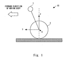
- Fig. 1 shows a sensor coordinate system of a moving body with a tilt angle estimating mechanism according to the present invention.
- the moving body 10 includes a vehicle body 1 and a wheel 2 fixed to the vehicle body 1 through a drive mechanism which is not shown.
- An axis which is orthogonal to a forward direction (that is, moving direction, pitch direction) of the moving body 10 and which extends in a substantially horizontal direction (that is, rolling direction) is set as an X-axis
- the forward direction (that is, moving direction, pitch direction) of the moving body 10 is set as a Y-axis
- a vertical direction thereof is set as a Z-axis.
- an angle formed between a line connecting the vehicle body 1 and a rotation center of the wheel 2, and the Z-axis is set as a tilt angle of a vehicle body.
- the moving body 10 includes a single-axis gyro sensor (angular velocity sensor) for measuring an angular velocity in an X-axis direction. Furthermore, in the moving body 10, a tilt angle estimating mechanism for inputting a detection signal of each of the acceleration sensor and the gyro sensor and a control signal to estimate (calculate) the tilt angle of the vehicle body is implemented by a computer.
- a single-axis gyro sensor angular velocity sensor
- a tilt angle estimating mechanism for inputting a detection signal of each of the acceleration sensor and the gyro sensor and a control signal to estimate (calculate) the tilt angle of the vehicle body is implemented by a computer.
- the tilt angle estimating mechanism includes: means for estimating a tilt angle based on the acceleration detected by the acceleration sensor; means for estimating a tilt angle based on the angular velocity detected by the gyro sensor; and means for estimating a tilt angle in accordance with the tilt angle based on the acceleration sensor and the tilt angle based on the gyro sensor, with a linear model equation of the moving body being regarded as an observer.
- the means for estimating the tilt angle performs estimation by setting the tilt angle based on the gyro sensor as a reference value for the observer and by performing feedback so that an estimated value follows the tilt angle based on the gyro sensor.
- Fig. 2 is a block diagram for explaining processing for estimating a tilt angle according to the present invention.
- a control signal is input to I 1
- an acceleration signal detected in the Y-axis direction by an Y-axis acceleration sensor is input to I 2
- an acceleration signal detected in the Z-axis direction by a Z-axis acceleration sensor is input to I 3
- an angular velocity signal detected by the single-axis gyro sensor is input to I 4 .
- a tilt angle of a vehicle body is geometrically calculated according to the above Equation (1).
- the accuracy of the tilt angle calculated here is high with respect to a direct current (DC) component to a low frequency range but is low with respect to a medium to high frequency range because disturbance is applied to the acceleration sensor during a motion involving acceleration/deceleration.
- DC direct current
- the control signal, the calculated tilt angle of the vehicle body, and the angular velocity detected by the gyro sensor are input. Further, feedback processing is performed by an external force observer to ultimately calculate a tilt angle, a tilt angular velocity, and an external force to be output from O 1 , O 2 , and O 3 , respectively.
- Equation (4) is taken into consideration because it is only necessary to carry out estimation of the tilt angle ⁇ of the vehicle body in the present invention.
- Equation (5) is used for obtaining a tilt angular velocity.
- the external force observer is created using Equation (6) as a basic model.
- a ⁇ term in the right-hand side of Equation (6) functions as an external force of the ⁇ equation.
- the estimation error is increased. Accordingly, in order to prevent the estimation error, the external force observer is constructed in consideration of an external force f as a state quantity.
- the external force observer can be expressed by the following Equation (10).
- X ⁇ ⁇ A ⁇ X ⁇ + Bu + K ⁇ Y - C ⁇ X ⁇ X ⁇ : estimated value
- K observer gain
- the observer gain (feedback gain) K represented in Equation (10) is set as K1, K2, and K3 for each of a state quantity ⁇ , a ⁇ dot, and f.
- an estimated convergence rate is determined. That is, according to the magnitude of a pole of the characteristic equation obtained from Equation (10), the estimated convergence rate is determined.
- K (K1, K2, K3)
- K1 is large
- K2 is made large
- K2 is made large.
- K2 is made large.
- K2 is made large.
- K2 is made large. If an operating frequency can be estimated in advance, K is set according to the frequency.
- K is determined by considering a trade-off between the following cases (A) and (B).
- the estimated value is determined such that higher priority is given to the observable, with the result that the effect of the basic model is reduced.
- the estimated value is likely to be affected by sensor noise. Further, in this case, the estimated convergence rate becomes higher.
- the observable which is an input of the acceleration sensor is greatly smoothed.
- the effect of the observable is reduced.
- the estimated value basically follows the basic model.
- the estimated value is hardly affected by the sensor noise. Further, in this case, the estimated convergence rate becomes lower.
- the observer gain K is set such that the high frequency component of the tilt angle, which is estimated based on the gyro sensor, is output as it is and such that the low frequency range and direct current components are set so as to obtain the tilt angle estimated based on the acceleration sensor, whereby the tilt angle can be estimated with high accuracy in a wide frequency range from the direct current component to the high frequency range.
- the external force observer employed in the present invention is provided so as to estimate the direct current component of the tilt angle, there is no problem if a response thereof is slow. A slower response indicates that noise can be further reduced, so the estimation with high accuracy is expected. Further, since the observer which is slow in response is employed, the pole is set to be relatively close to the real axis.
- the equation of motion (model information) corresponding to the tilt angle is used as the external force observer.
- the tilt angle is estimated with high accuracy in the medium to high frequency range.
- the tilt angle estimated based on the biaxial acceleration sensor as well as the single-axis gyro sensor is set as a reference value for the observer, and feedback control is executed so that the estimated value follows the reference value.
- the tilt angle can be estimated with high accuracy in a wide frequency range from the direct current component to the high frequency range.
- the effect of noise of the acceleration sensor can be reduced by appropriately setting the observer gain K.
- the external force observer of a continuous system as ultimately designed is discretized, thereby making it possible to design the external force observer.
- the control of the observer gain K is executed by a control mechanism.
- Fig. 3 shows a flowchart of the control.
- the control mechanism determines whether the angular velocity detected by the gyro sensor or the like is within a predetermined range (S101).
- the angular velocity is set as a reference because it is possible to detect whether the moving body is in the longitudinal acceleration state. Accordingly, in the example shown in Fig. 3 , it is detected whether the moving body is in the longitudinal acceleration state based on the angular velocity.
- the present invention is not limited thereto, and it may be detected whether the moving body is in the longitudinal acceleration state based on another parameter.
- the control mechanism does not execute the control for changing the value of the observer gain K.
- the control mechanism when determining that the angular velocity is not within the predetermined range, that is, out of the predetermined range, the control mechanism further determines whether the angular velocity is higher than the predetermined range (S102). As a result of the determination, when determining that the angular velocity is higher than the predetermined range, the control mechanism executes control for making the value of the observer gain K small (S103).
- the moving body is in the longitudinal acceleration state and is in a state where disturbance noise is more likely to occur in the acceleration sensor, so the effect on the acceleration sensor can be reduced.
- the control mechanism executes control for making the value of the observer gain K large (S104).
- the magnitude of the value of the observer gain K may be controlled by selecting one of an output value obtained when the estimation processing is executed by making the observer gain K small, and an output value obtained when the estimation processing is executed by making the observer gain K large.
- control is executed such that the tilt angle estimation is not carried out based on the sensor that is out of order, that is, such that the tilt angle estimation is carried out based on only the sensor that is not out of order.
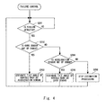
- the control mechanism determines whether a failure such as disconnection or a sensor failure is detected by a watchdog or the like (S201). When determining that the failure is detected, the control mechanism determines whether the gyro sensor is out of order (S202). When determining that the gyro sensor is out of order, the control mechanism estimates the tilt angle of the vehicle body by using the acceleration sensor that is not out of order (S203). Meanwhile, when determining that the gyro sensor is not out of order, the control mechanism determines that the acceleration sensor is out of order (S204).
- a failure such as disconnection or a sensor failure is detected by a watchdog or the like
- the control mechanism estimates the tilt angle of the vehicle body by using the gyro sensor that is not out of order (S205).
- the control mechanism stops the estimation processing (S206).
- the use of model information of the moving body enables improvement of the accuracy of estimating the tilt angle.
- the estimation processing is executed by limiting the estimated value to the predetermined value when the estimated value exceeds the predetermined value, whereby a deviation between the true value and the estimated value is limited. As a result, it is possible to prevent degradation of the estimation accuracy.
- the moving body 10 is an inverted two-wheeled unstable vehicle, but the present invention is not limited thereto.
- a walking type moving body or a caterpillar-driven moving body may be employed.
- the moving body 10 can be applied to a boarding-type moving body, a moving body incorporated into the lower body of a robot, and a moving body that moves while carrying a load.
- the present invention relates to a moving body with a tilt angle estimating mechanism, and more particularly, the present invention is widely applicable to an inverted two-wheeled vehicle with a tilt angle estimating mechanism.
Landscapes
- Physics & Mathematics (AREA)
- General Physics & Mathematics (AREA)
- Engineering & Computer Science (AREA)
- Radar, Positioning & Navigation (AREA)
- Remote Sensing (AREA)
- Motorcycle And Bicycle Frame (AREA)
- Control Of Position, Course, Altitude, Or Attitude Of Moving Bodies (AREA)
- Length Measuring Devices With Unspecified Measuring Means (AREA)
- Gyroscopes (AREA)
Abstract
Description
- The present invention relates to a moving body with a tilt angle estimating mechanism, and more particularly, to an inverted two-wheeled vehicle with a tilt angle estimating mechanism.
- For a moving body such as an inverted two-wheeled vehicle, it is necessary to estimate a tilt angle with high accuracy in order to maintain an inverted posture. Not only for the two-wheeled type vehicle but also for a walking type moving body or a caterpillar-driven moving body, the estimation of the tilt angle with high accuracy is required.
- Conventionally, mechanisms for estimating a tilt angle include a system using a gyro (angular velocity) sensor and a system using an acceleration sensor. In the system using a gyro sensor, a tilt angle is obtained by integrating an output signal of the gyro sensor. However, an offset noise is originally superimposed on the output signal of the gyro sensor, so there is a problem in that a deviation from a true value is gradually increased.
- In the system using an acceleration sensor, the tilt angle is calculated using a geometric relation obtained by a two or more axial acceleration sensor. According to the system, the tilt angle is calculated from values of a biaxial gravity acceleration, so there is a problem in that the estimation accuracy is degraded unless the estimation is carried out in a static state. In particular, when the moving body is accelerated/decelerated, a component generated by the acceleration/deceleration is superimposed as noise on the biaxial acceleration sensor.
- Further, there is also proposed a system for estimating a tilt angle by an autonomous inertia navigation system (INS) using a gyro sensor and a triaxial acceleration sensor. However, the problem of the offset noise in the gyro sensor and the problem of the noise caused by the acceleration/deceleration of the acceleration sensor as described above are still unsolved.
- Note that
Patent Document 1 discloses a technique for using a gyro sensor and an accelerometer to be switched for each frequency band. However, the technique is not relevant to the moving body with a tilt angle estimating mechanism. - [Patent Document 1] Japanese Unexamined Patent Application Publication No.
4-346021 - As described above, the use of a gyro sensor or an acceleration sensor enables obtainment of a tilt angle of a vehicle body, but the accuracy thereof is a problem.
- The present invention has been made to solve the above-mentioned problem, and it is an object of the present invention to provide a moving body with a tilt angle estimating mechanism capable of estimating a tilt angle of a vehicle body with high accuracy.
- A moving body according to the present invention includes: an acceleration sensor for detecting an acceleration in two axial directions; a gyro sensor for detecting an angular velocity of a vehicle body; and a tilt angle estimating mechanism for estimating a tilt angle of the vehicle body, in which the tilt angle estimating mechanism includes: means for estimating a first tilt angle based on the acceleration detected by the acceleration sensor; means for estimating a second tilt angle based on the angular velocity detected by the gyro sensor according to a linear model equation of the moving body; and means for estimating a tilt angle by executing feedback control so that the second tilt angle follows the first tilt angle with the first tilt angle being set as a reference value for an observer.
- Here, it is desirable that the tilt angle estimating mechanism include setting means for setting an observer gain K for adjusting the effect of the first tilt angle, to an arbitrary value.
- Further, the setting means may set the observer gain K to a small value when the moving body is in a longitudinal acceleration state.
- In addition, it is desirable that the setting means set the observer gain K according to a failure condition of each of the acceleration sensor and the gyro sensor.
Further, a low-pass filter may be provided in a subsequent stage of the acceleration sensor.
A moving body according to a preferred embodiment of the present invention is an inverted two-wheeled vehicle. - According to the present invention, it is possible to provide a moving body with a tilt angle estimating mechanism capable of estimating a tilt angle of a vehicle body with high accuracy.
-
-
Fig. 1 is a diagram for explaining a sensor coordinate system of a moving body according to an embodiment of the present invention. -
Fig. 2 is a block diagram showing a method of estimating a tilt angle of a moving body according to the embodiment of the present invention. -
Fig. 3 is a flowchart showing the method of estimating a tilt angle of a moving body according to the embodiment of the present invention. -
Fig. 4 is a flowchart showing the method of estimating a tilt angle of a moving body according to the embodiment of the present invention. -
- 1
- VEHICLE BODY
- 2
- WHEEL
- 10
- MOVING BODY
-
Fig. 1 shows a sensor coordinate system of a moving body with a tilt angle estimating mechanism according to the present invention. As shown inFig. 1 , the movingbody 10 includes avehicle body 1 and awheel 2 fixed to thevehicle body 1 through a drive mechanism which is not shown. - An axis which is orthogonal to a forward direction (that is, moving direction, pitch direction) of the
moving body 10 and which extends in a substantially horizontal direction (that is, rolling direction) is set as an X-axis, the forward direction (that is, moving direction, pitch direction) of themoving body 10 is set as a Y-axis, and a vertical direction thereof is set as a Z-axis. In this example, an angle formed between a line connecting thevehicle body 1 and a rotation center of thewheel 2, and the Z-axis is set as a tilt angle of a vehicle body. - The moving
body 10 includes an acceleration sensor for measuring accelerations in a Y-axis direction and a Z-axis direction, and a low-pass filter which is provided in a subsequent stage thereof and which has a low cutoff frequency. Based on accelerations u(1) and u(2) which are detected in the Y-axis direction and the Z-axis direction, respectively, by those two acceleration sensors, a tilt angle of a vehicle body (that is, pitch angle) η can be obtained according to the following equation.
- Further, the moving
body 10 includes a single-axis gyro sensor (angular velocity sensor) for measuring an angular velocity in an X-axis direction. Furthermore, in themoving body 10, a tilt angle estimating mechanism for inputting a detection signal of each of the acceleration sensor and the gyro sensor and a control signal to estimate (calculate) the tilt angle of the vehicle body is implemented by a computer. - The tilt angle estimating mechanism includes: means for estimating a tilt angle based on the acceleration detected by the acceleration sensor; means for estimating a tilt angle based on the angular velocity detected by the gyro sensor; and means for estimating a tilt angle in accordance with the tilt angle based on the acceleration sensor and the tilt angle based on the gyro sensor, with a linear model equation of the moving body being regarded as an observer. In this case, the means for estimating the tilt angle performs estimation by setting the tilt angle based on the gyro sensor as a reference value for the observer and by performing feedback so that an estimated value follows the tilt angle based on the gyro sensor.
-
Fig. 2 is a block diagram for explaining processing for estimating a tilt angle according to the present invention. As shown in the figure, a control signal is input to I1, an acceleration signal detected in the Y-axis direction by an Y-axis acceleration sensor is input to I2, an acceleration signal detected in the Z-axis direction by a Z-axis acceleration sensor is input to I3, and an angular velocity signal detected by the single-axis gyro sensor is input to I4. - First, based on the acceleration in the Y-axis direction, which is input to I2, and based on the acceleration in the Z-axis direction, which is input to I3, a tilt angle of a vehicle body is geometrically calculated according to the above Equation (1). The accuracy of the tilt angle calculated here is high with respect to a direct current (DC) component to a low frequency range but is low with respect to a medium to high frequency range because disturbance is applied to the acceleration sensor during a motion involving acceleration/deceleration.
- Next, the control signal, the calculated tilt angle of the vehicle body, and the angular velocity detected by the gyro sensor are input. Further, feedback processing is performed by an external force observer to ultimately calculate a tilt angle, a tilt angular velocity, and an external force to be output from O1, O2, and O3, respectively. Note that, in
Fig. 2 , an equation regarding the external force observer, y(n) = Cx(n) + Du(n), is defined as Equation (2), and x(n + 1) = Ax(n) + Bu(n) is defined as Equation (3). - Next, details of design of the external force observer are described.
First, linear modeling for the tilt angle of the vehicle body is executed. A vehicle body model (equation of motion) of an inverted two-wheel vehicle can be expressed by the following equation:

where η represents a tilt angle of a vehicle body; θ: a rotation angle of a wheel; m1: a mass of a vehicle body; m2: a mass of a wheel; 1: a distance between a center of gravity of a vehicle body and an axle; J1: an inertia moment about a center of gravity of a vehicle body; Jm: an inertia moment of a motor rotor; Jw: an inertia moment about a rotation axis of a wheel; n: a gear ratio (motor : wheel = 1 : n); r: a wheel radius; fr: a resistance of a drive system; and u: a torque value of a motor. - Of the above Equations (4) and (5), only Equation (4) is taken into consideration because it is only necessary to carry out estimation of the tilt angle η of the vehicle body in the present invention. Note that Equation (5) is used for obtaining a tilt angular velocity. When the left-hand side of Equation (4) is expressed using "η", Equation (6) is obtained as follows.

- The external force observer is created using Equation (6) as a basic model. Here, a θ term in the right-hand side of Equation (6) functions as an external force of the η equation. In the present invention, when the θ term is neglected, the estimation error is increased. Accordingly, in order to prevent the estimation error, the external force observer is constructed in consideration of an external force f as a state quantity.
- Next, derivation of the basic model for the external force observer is described. Now, the state quantity is defined by the following Equation (7):

where f represents an external force. - When Equation (6) is changed to a state equation representation by using the state quantity represented in Equation (7), Equations (8) and (9) are obtained as follows:


where the external force f is set in a stepwise manner so as to obtain a constant value in a sample period, and a derivative value obtained in the period is set to 0. - Next, a description is given of a method of determining a gain of the external force observer.
The external force observer can be expressed by the following Equation (10).
- The observer gain (feedback gain) K represented in Equation (10) is set as K1, K2, and K3 for each of a state quantity η, a η dot, and f. According to the magnitude of the observer gain K represented in Equation (10), an estimated convergence rate is determined. That is, according to the magnitude of a pole of the characteristic equation obtained from Equation (10), the estimated convergence rate is determined.
Assuming that K = (K1, K2, K3), when K1 is large, the estimated convergence rate approaches an estimated value obtained by the acceleration sensor, and when K2 is large, the estimated convergence rate approaches an estimated value obtained by the gyro sensor. At low frequencies, it is determined that the estimated value obtained by the acceleration sensor is correct, so K2 is made large. At medium to high frequencies, K2 is made large. If an operating frequency can be estimated in advance, K is set according to the frequency. - Specifically, K is determined by considering a trade-off between the following cases (A) and (B).
- In this case, the effect of an observable which is an input of the acceleration sensor is increased. Accordingly, the estimated value is determined such that higher priority is given to the observable, with the result that the effect of the basic model is reduced. Thus, the estimated value is likely to be affected by sensor noise. Further, in this case, the estimated convergence rate becomes higher.
- In this case, the observable which is an input of the acceleration sensor is greatly smoothed. In other words, the effect of the observable is reduced. Accordingly, the estimated value basically follows the basic model. As a result, the estimated value is hardly affected by the sensor noise. Further, in this case, the estimated convergence rate becomes lower.
- The observer gain K is set such that the high frequency component of the tilt angle, which is estimated based on the gyro sensor, is output as it is and such that the low frequency range and direct current components are set so as to obtain the tilt angle estimated based on the acceleration sensor, whereby the tilt angle can be estimated with high accuracy in a wide frequency range from the direct current component to the high frequency range.
- Since the external force observer employed in the present invention is provided so as to estimate the direct current component of the tilt angle, there is no problem if a response thereof is slow. A slower response indicates that noise can be further reduced, so the estimation with high accuracy is expected. Further, since the observer which is slow in response is employed, the pole is set to be relatively close to the real axis.
- In the present invention, as described above, the equation of motion (model information) corresponding to the tilt angle is used as the external force observer. Based on the model information and the angular velocity detected by the single-axis gyro sensor, the tilt angle is estimated with high accuracy in the medium to high frequency range. Further, in the present invention, the tilt angle estimated based on the biaxial acceleration sensor as well as the single-axis gyro sensor is set as a reference value for the observer, and feedback control is executed so that the estimated value follows the reference value. As a result, the tilt angle can be estimated with high accuracy in a wide frequency range from the direct current component to the high frequency range. Furthermore, the effect of noise of the acceleration sensor can be reduced by appropriately setting the observer gain K.
- The external force observer of a continuous system as ultimately designed is discretized, thereby making it possible to design the external force observer.
- Further, in the present invention, the control of the observer gain K is executed by a control mechanism.
Fig. 3 shows a flowchart of the control. First, the control mechanism determines whether the angular velocity detected by the gyro sensor or the like is within a predetermined range (S101). Here, the angular velocity is set as a reference because it is possible to detect whether the moving body is in the longitudinal acceleration state. Accordingly, in the example shown inFig. 3 , it is detected whether the moving body is in the longitudinal acceleration state based on the angular velocity. However, the present invention is not limited thereto, and it may be detected whether the moving body is in the longitudinal acceleration state based on another parameter. When determining that the angular velocity is within the predetermined range, the control mechanism does not execute the control for changing the value of the observer gain K. - Next, when determining that the angular velocity is not within the predetermined range, that is, out of the predetermined range, the control mechanism further determines whether the angular velocity is higher than the predetermined range (S102). As a result of the determination, when determining that the angular velocity is higher than the predetermined range, the control mechanism executes control for making the value of the observer gain K small (S103). Thus, the moving body is in the longitudinal acceleration state and is in a state where disturbance noise is more likely to occur in the acceleration sensor, so the effect on the acceleration sensor can be reduced.
- As a result of the determination, when determining that the angular velocity is not higher than the predetermined range, that is, lower than the predetermined range, the control mechanism executes control for making the value of the observer gain K large (S104). Note that the magnitude of the value of the observer gain K may be controlled by selecting one of an output value obtained when the estimation processing is executed by making the observer gain K small, and an output value obtained when the estimation processing is executed by making the observer gain K large.
- Next, a description is given of a failure control for the sensors. Though the gyro sensor and the acceleration sensor are provided in the present invention, when one of the sensors is out of order, control is executed such that the tilt angle estimation is not carried out based on the sensor that is out of order, that is, such that the tilt angle estimation is carried out based on only the sensor that is not out of order.
- Specifically, the control mechanism determines whether a failure such as disconnection or a sensor failure is detected by a watchdog or the like (S201). When determining that the failure is detected, the control mechanism determines whether the gyro sensor is out of order (S202). When determining that the gyro sensor is out of order, the control mechanism estimates the tilt angle of the vehicle body by using the acceleration sensor that is not out of order (S203). Meanwhile, when determining that the gyro sensor is not out of order, the control mechanism determines that the acceleration sensor is out of order (S204). As a result of the determination, when determining that the acceleration sensor is out of order, the control mechanism estimates the tilt angle of the vehicle body by using the gyro sensor that is not out of order (S205). When determining that the acceleration sensor is not out of order, the control mechanism stops the estimation processing (S206).
- Further, in the present invention, the use of model information of the moving body enables improvement of the accuracy of estimating the tilt angle. For example, in a case where the tilt angle is smaller than a predetermined value due to restrictions on the structure of a vehicle, the estimation processing is executed by limiting the estimated value to the predetermined value when the estimated value exceeds the predetermined value, whereby a deviation between the true value and the estimated value is limited. As a result, it is possible to prevent degradation of the estimation accuracy.
- Note that, in the above-mentioned example, the moving
body 10 is an inverted two-wheeled unstable vehicle, but the present invention is not limited thereto. A walking type moving body or a caterpillar-driven moving body may be employed. Further, the movingbody 10 can be applied to a boarding-type moving body, a moving body incorporated into the lower body of a robot, and a moving body that moves while carrying a load. - The present invention relates to a moving body with a tilt angle estimating mechanism, and more particularly, the present invention is widely applicable to an inverted two-wheeled vehicle with a tilt angle estimating mechanism.
Claims (6)
- A moving body, comprising:an acceleration sensor for detecting an acceleration in two axial directions;a gyro sensor for detecting an angular velocity of a vehicle body; anda tilt angle estimating mechanism for estimating a tilt angle of the vehicle body,wherein the tilt angle estimating mechanism includes:means for estimating a first tilt angle based on the acceleration detected by the acceleration sensor;means for estimating a second tilt angle based on the angular velocity detected by the gyro sensor according to a linear model equation of the moving body; andmeans for estimating a tilt angle by executing feedback control so that the second tilt angle follows the first tilt angle, with the first tilt angle being set as a reference value for an observer.
- The moving body according to claim 1, wherein the tilt angle estimating mechanism includes setting means for setting an observer gain K for adjusting an effect of the first tilt angle, to an arbitrary value.
- The moving body according to claim 2, wherein the setting means sets the observer gain K to a small value when the moving body is in a longitudinal acceleration state.
- The moving body according to claim 2, wherein the setting means sets the observer gain K according to a failure condition of each of the acceleration sensor and the gyro sensor.
- The moving body according to any one of claims 1 to 4, wherein the acceleration sensor includes a low-pass filter provided in a subsequent stage thereof.
- The moving body according to any one of claims 1 to 5, wherein the moving body is an inverted two-wheeled vehicle.
Applications Claiming Priority (2)
| Application Number | Priority Date | Filing Date | Title |
|---|---|---|---|
| JP2006273622A JP4281777B2 (en) | 2006-10-05 | 2006-10-05 | Mobile object with tilt angle estimation mechanism |
| PCT/JP2007/069404 WO2008041732A1 (en) | 2006-10-05 | 2007-09-27 | Moving object with tilt angle estimating mechanism |
Publications (3)
| Publication Number | Publication Date |
|---|---|
| EP2077432A1 true EP2077432A1 (en) | 2009-07-08 |
| EP2077432A4 EP2077432A4 (en) | 2012-11-14 |
| EP2077432B1 EP2077432B1 (en) | 2014-03-19 |
Family
ID=39268585
Family Applications (1)
| Application Number | Title | Priority Date | Filing Date |
|---|---|---|---|
| EP07829143.2A Not-in-force EP2077432B1 (en) | 2006-10-05 | 2007-09-27 | Moving object with tilt angle estimating mechanism |
Country Status (5)
| Country | Link |
|---|---|
| US (1) | US8000925B2 (en) |
| EP (1) | EP2077432B1 (en) |
| JP (1) | JP4281777B2 (en) |
| CN (1) | CN101443628B (en) |
| WO (1) | WO2008041732A1 (en) |
Cited By (2)
| Publication number | Priority date | Publication date | Assignee | Title |
|---|---|---|---|---|
| CN102174884A (en) * | 2011-02-28 | 2011-09-07 | 重庆华渝电气仪表总厂 | Directional gyro inclinometer spot measurement device |
| FR2999699A1 (en) * | 2012-12-19 | 2014-06-20 | Commissariat Energie Atomique | METHOD FOR DETERMINING THE INCLINATION OF AN OBJECT |
Families Citing this family (28)
| Publication number | Priority date | Publication date | Assignee | Title |
|---|---|---|---|---|
| WO2010032493A1 (en) * | 2008-09-17 | 2010-03-25 | 株式会社村田製作所 | Fall prevention controller and computer program |
| JP5109990B2 (en) * | 2009-01-26 | 2012-12-26 | 株式会社エクォス・リサーチ | vehicle |
| WO2010084762A1 (en) * | 2009-01-26 | 2010-07-29 | 株式会社エクォス・リサーチ | Vehicle |
| JP5110009B2 (en) * | 2009-03-11 | 2012-12-26 | 株式会社エクォス・リサーチ | vehicle |
| US8443920B2 (en) * | 2009-09-18 | 2013-05-21 | Honda Motor Co., Ltd. | Inverted pendulum type vehicle |
| JP5488095B2 (en) * | 2010-03-23 | 2014-05-14 | トヨタ自動車株式会社 | Inverted moving body and control method thereof |
| US9429940B2 (en) | 2011-01-05 | 2016-08-30 | Sphero, Inc. | Self propelled device with magnetic coupling |
| US9090214B2 (en) | 2011-01-05 | 2015-07-28 | Orbotix, Inc. | Magnetically coupled accessory for a self-propelled device |
| US10281915B2 (en) | 2011-01-05 | 2019-05-07 | Sphero, Inc. | Multi-purposed self-propelled device |
| US9114838B2 (en) | 2011-01-05 | 2015-08-25 | Sphero, Inc. | Self-propelled device for interpreting input from a controller device |
| US9218316B2 (en) | 2011-01-05 | 2015-12-22 | Sphero, Inc. | Remotely controlling a self-propelled device in a virtualized environment |
| JP5429427B2 (en) | 2011-02-23 | 2014-02-26 | 株式会社村田製作所 | Walking assistance vehicle |
| US8548722B2 (en) * | 2011-08-12 | 2013-10-01 | Deere & Company | Tilt sensor and method for determining the tilt of a vehicle |
| HK1207455A1 (en) | 2012-05-14 | 2016-01-29 | 斯飞乐有限公司 | Operating a computing device by detecting rounded objects in an image |
| US9827487B2 (en) | 2012-05-14 | 2017-11-28 | Sphero, Inc. | Interactive augmented reality using a self-propelled device |
| US10056791B2 (en) * | 2012-07-13 | 2018-08-21 | Sphero, Inc. | Self-optimizing power transfer |
| EP2910460B1 (en) * | 2012-10-16 | 2018-02-21 | Toyota Jidosha Kabushiki Kaisha | Inverted mobile body and control method thereof |
| JP5907037B2 (en) * | 2012-10-16 | 2016-04-20 | 株式会社豊田中央研究所 | Moving body |
| JP6123906B2 (en) * | 2013-10-10 | 2017-05-10 | 株式会社村田製作所 | Wheelbarrow |
| US9829882B2 (en) | 2013-12-20 | 2017-11-28 | Sphero, Inc. | Self-propelled device with center of mass drive system |
| JP5979322B2 (en) * | 2013-12-25 | 2016-08-24 | 株式会社村田製作所 | Wheelbarrow |
| CN104296722B (en) * | 2014-01-07 | 2017-11-14 | 郑州宇通客车股份有限公司 | Vehicle roll condition detection method |
| JP5962689B2 (en) * | 2014-02-14 | 2016-08-03 | トヨタ自動車株式会社 | Autonomous mobile body and failure determination method thereof |
| JP6187310B2 (en) * | 2014-02-24 | 2017-08-30 | トヨタ自動車株式会社 | Inverted moving body |
| KR20170070944A (en) * | 2015-12-14 | 2017-06-23 | 현대오트론 주식회사 | Apparatus for pitch angle detecting of vehicle using gyro sensor and acceleration sensor and method therof |
| CN105509693B (en) * | 2015-12-31 | 2018-04-06 | 山东科技大学 | A kind of portable middle part chute detection means and its application |
| US10551407B2 (en) * | 2016-07-29 | 2020-02-04 | Blackberry Limited | Determining an open/close status of a barrier |
| CN110514178B (en) * | 2019-09-03 | 2021-11-26 | 北京源清慧虹信息科技有限公司 | Inclination angle measuring method and device based on single-axis acceleration sensor |
Family Cites Families (13)
| Publication number | Priority date | Publication date | Assignee | Title |
|---|---|---|---|---|
| JP2653197B2 (en) | 1989-12-18 | 1997-09-10 | 日産自動車株式会社 | Rolling control device for vehicle |
| JPH0797033B2 (en) | 1991-05-23 | 1995-10-18 | 日本航空電子工業株式会社 | Electrostatic levitation starter |
| US6581714B1 (en) * | 1993-02-24 | 2003-06-24 | Deka Products Limited Partnership | Steering control of a personal transporter |
| US6678631B2 (en) * | 1998-11-19 | 2004-01-13 | Delphi Technologies, Inc. | Vehicle attitude angle estimator and method |
| JP2002318274A (en) | 2001-02-13 | 2002-10-31 | Mazda Motor Corp | Body movement measurement apparatus, body movement measurement method, and recording medium recording the method |
| WO2003016031A1 (en) | 2001-08-16 | 2003-02-27 | Riken | Rapid prototyping method and device using v-cad data |
| KR100956539B1 (en) * | 2002-04-26 | 2010-05-07 | 혼다 기켄 고교 가부시키가이샤 | Magnetic Posture Estimator for Legged Mobile Robot |
| JP4138546B2 (en) | 2003-03-26 | 2008-08-27 | トヨタ自動車株式会社 | Mobile cart and control method of mobile cart |
| JP4145741B2 (en) * | 2003-07-03 | 2008-09-03 | 三菱電機株式会社 | Vehicle rollover discrimination device and vehicle rollover discrimination method |
| US7363993B2 (en) * | 2003-11-04 | 2008-04-29 | Toyota Jidosha Kabushiki Kaisha | Traveling apparatus and method for controlling thereof |
| DE10360728A1 (en) | 2003-12-23 | 2005-07-21 | Daimlerchrysler Ag | Method and device for determining a vehicle condition |
| US7222007B2 (en) * | 2004-01-07 | 2007-05-22 | Ford Global Technologies, Llc | Attitude sensing system for an automotive vehicle relative to the road |
| JP4315918B2 (en) | 2005-02-09 | 2009-08-19 | 株式会社クボタ | Inclination angle measuring device |
-
2006
- 2006-10-05 JP JP2006273622A patent/JP4281777B2/en active Active
-
2007
- 2007-09-27 WO PCT/JP2007/069404 patent/WO2008041732A1/en not_active Ceased
- 2007-09-27 EP EP07829143.2A patent/EP2077432B1/en not_active Not-in-force
- 2007-09-27 US US12/297,323 patent/US8000925B2/en not_active Expired - Fee Related
- 2007-09-27 CN CN2007800175536A patent/CN101443628B/en not_active Expired - Fee Related
Cited By (4)
| Publication number | Priority date | Publication date | Assignee | Title |
|---|---|---|---|---|
| CN102174884A (en) * | 2011-02-28 | 2011-09-07 | 重庆华渝电气仪表总厂 | Directional gyro inclinometer spot measurement device |
| FR2999699A1 (en) * | 2012-12-19 | 2014-06-20 | Commissariat Energie Atomique | METHOD FOR DETERMINING THE INCLINATION OF AN OBJECT |
| EP2746722A1 (en) * | 2012-12-19 | 2014-06-25 | Commissariat à l'Énergie Atomique et aux Énergies Alternatives | Method for determining the inclination of an object |
| US9476708B2 (en) | 2012-12-19 | 2016-10-25 | Commissariat à l'énergie atomique et aux énergies alternatives | Accelerometer based attitude determination |
Also Published As
| Publication number | Publication date |
|---|---|
| EP2077432B1 (en) | 2014-03-19 |
| WO2008041732A1 (en) | 2008-04-10 |
| US20090138232A1 (en) | 2009-05-28 |
| JP4281777B2 (en) | 2009-06-17 |
| EP2077432A4 (en) | 2012-11-14 |
| JP2008089531A (en) | 2008-04-17 |
| CN101443628A (en) | 2009-05-27 |
| US8000925B2 (en) | 2011-08-16 |
| WO2008041732A8 (en) | 2008-07-03 |
| CN101443628B (en) | 2010-12-08 |
Similar Documents
| Publication | Publication Date | Title |
|---|---|---|
| EP2077432B1 (en) | Moving object with tilt angle estimating mechanism | |
| JP7036080B2 (en) | Inertial navigation system | |
| US12000702B2 (en) | Dynamic gyroscope bias offset compensation | |
| EP2517941B1 (en) | Roll angle estimation device and transport equipment | |
| US8200452B2 (en) | Attitude-angle detecting apparatus and attitude-angle detecting method | |
| US8583354B2 (en) | Continuous computation of center of gravity of a vehicle | |
| JP5029442B2 (en) | Vehicle attitude angle estimation device and program | |
| CN110217239B (en) | Method and equipment for measuring yaw rate of vehicle | |
| JP2008076389A (en) | Navigation system and navigation method | |
| CN107074241A (en) | Estimate the method for vehicle side-slip angle, implement the computer program of methods described, be mounted with the control unit of the computer program and the vehicle including described control unit | |
| US20220252399A1 (en) | Composite sensor and angular velocity correction method | |
| AU2015305864B2 (en) | Earthmoving machine comprising weighted state estimator | |
| US12151764B2 (en) | Body posture detection device and straddle type vehicle | |
| CN109677415B (en) | Apparatus and method for estimating radius of curvature of a vehicle | |
| KR101733880B1 (en) | Apparatus and method for estimating position of vehicle using nonlinear tire model | |
| KR20110108208A (en) | Driving mode determination method, navigation system using the driving mode determination and its providing method | |
| US20060041367A1 (en) | Vehicle stabilizing control apparatus | |
| JP6900341B2 (en) | Position calculation device and dump truck | |
| JP2009198279A (en) | On-vehicle navigation system and navigation method | |
| JP7360976B2 (en) | Sensor error correction device | |
| JP6409625B2 (en) | Vehicle position calculation device | |
| KR20160103750A (en) | Apparatus and method for estimating radius of curvature in vehicle | |
| EP2505498B1 (en) | Method and system for detecting forces on aircraft | |
| Adabala | Precision in Pitch and Roll: A Critical Component for Stability, Control, and Safety in Automotive and Electronics Systems | |
| JP2006145259A (en) | Status detection apparatus and status calculation method thereof |
Legal Events
| Date | Code | Title | Description |
|---|---|---|---|
| PUAI | Public reference made under article 153(3) epc to a published international application that has entered the european phase |
Free format text: ORIGINAL CODE: 0009012 |
|
| 17P | Request for examination filed |
Effective date: 20090501 |
|
| AK | Designated contracting states |
Kind code of ref document: A1 Designated state(s): AT BE BG CH CY CZ DE DK EE ES FI FR GB GR HU IE IS IT LI LT LU LV MC MT NL PL PT RO SE SI SK TR |
|
| DAX | Request for extension of the european patent (deleted) | ||
| A4 | Supplementary search report drawn up and despatched |
Effective date: 20121016 |
|
| RIC1 | Information provided on ipc code assigned before grant |
Ipc: G01B 21/22 20060101ALI20121010BHEP Ipc: B62K 3/00 20060101ALI20121010BHEP Ipc: G01C 9/08 20060101AFI20121010BHEP |
|
| RAP1 | Party data changed (applicant data changed or rights of an application transferred) |
Owner name: TOYOTA JIDOSHA KABUSHIKI KAISHA |
|
| GRAP | Despatch of communication of intention to grant a patent |
Free format text: ORIGINAL CODE: EPIDOSNIGR1 |
|
| INTG | Intention to grant announced |
Effective date: 20131008 |
|
| GRAS | Grant fee paid |
Free format text: ORIGINAL CODE: EPIDOSNIGR3 |
|
| GRAA | (expected) grant |
Free format text: ORIGINAL CODE: 0009210 |
|
| AK | Designated contracting states |
Kind code of ref document: B1 Designated state(s): AT BE BG CH CY CZ DE DK EE ES FI FR GB GR HU IE IS IT LI LT LU LV MC MT NL PL PT RO SE SI SK TR |
|
| REG | Reference to a national code |
Ref country code: GB Ref legal event code: FG4D |
|
| REG | Reference to a national code |
Ref country code: CH Ref legal event code: EP |
|
| REG | Reference to a national code |
Ref country code: IE Ref legal event code: FG4D |
|
| REG | Reference to a national code |
Ref country code: AT Ref legal event code: REF Ref document number: 657952 Country of ref document: AT Kind code of ref document: T Effective date: 20140415 |
|
| REG | Reference to a national code |
Ref country code: DE Ref legal event code: R096 Ref document number: 602007035690 Country of ref document: DE Effective date: 20140430 |
|
| PG25 | Lapsed in a contracting state [announced via postgrant information from national office to epo] |
Ref country code: LT Free format text: LAPSE BECAUSE OF FAILURE TO SUBMIT A TRANSLATION OF THE DESCRIPTION OR TO PAY THE FEE WITHIN THE PRESCRIBED TIME-LIMIT Effective date: 20140319 |
|
| REG | Reference to a national code |
Ref country code: NL Ref legal event code: VDEP Effective date: 20140319 |
|
| REG | Reference to a national code |
Ref country code: AT Ref legal event code: MK05 Ref document number: 657952 Country of ref document: AT Kind code of ref document: T Effective date: 20140319 |
|
| REG | Reference to a national code |
Ref country code: LT Ref legal event code: MG4D |
|
| PG25 | Lapsed in a contracting state [announced via postgrant information from national office to epo] |
Ref country code: FI Free format text: LAPSE BECAUSE OF FAILURE TO SUBMIT A TRANSLATION OF THE DESCRIPTION OR TO PAY THE FEE WITHIN THE PRESCRIBED TIME-LIMIT Effective date: 20140319 Ref country code: CY Free format text: LAPSE BECAUSE OF FAILURE TO SUBMIT A TRANSLATION OF THE DESCRIPTION OR TO PAY THE FEE WITHIN THE PRESCRIBED TIME-LIMIT Effective date: 20140319 Ref country code: SE Free format text: LAPSE BECAUSE OF FAILURE TO SUBMIT A TRANSLATION OF THE DESCRIPTION OR TO PAY THE FEE WITHIN THE PRESCRIBED TIME-LIMIT Effective date: 20140319 |
|
| PG25 | Lapsed in a contracting state [announced via postgrant information from national office to epo] |
Ref country code: LV Free format text: LAPSE BECAUSE OF FAILURE TO SUBMIT A TRANSLATION OF THE DESCRIPTION OR TO PAY THE FEE WITHIN THE PRESCRIBED TIME-LIMIT Effective date: 20140319 |
|
| PG25 | Lapsed in a contracting state [announced via postgrant information from national office to epo] |
Ref country code: BE Free format text: LAPSE BECAUSE OF FAILURE TO SUBMIT A TRANSLATION OF THE DESCRIPTION OR TO PAY THE FEE WITHIN THE PRESCRIBED TIME-LIMIT Effective date: 20140319 Ref country code: CZ Free format text: LAPSE BECAUSE OF FAILURE TO SUBMIT A TRANSLATION OF THE DESCRIPTION OR TO PAY THE FEE WITHIN THE PRESCRIBED TIME-LIMIT Effective date: 20140319 Ref country code: NL Free format text: LAPSE BECAUSE OF FAILURE TO SUBMIT A TRANSLATION OF THE DESCRIPTION OR TO PAY THE FEE WITHIN THE PRESCRIBED TIME-LIMIT Effective date: 20140319 Ref country code: RO Free format text: LAPSE BECAUSE OF FAILURE TO SUBMIT A TRANSLATION OF THE DESCRIPTION OR TO PAY THE FEE WITHIN THE PRESCRIBED TIME-LIMIT Effective date: 20140319 Ref country code: IS Free format text: LAPSE BECAUSE OF FAILURE TO SUBMIT A TRANSLATION OF THE DESCRIPTION OR TO PAY THE FEE WITHIN THE PRESCRIBED TIME-LIMIT Effective date: 20140719 Ref country code: EE Free format text: LAPSE BECAUSE OF FAILURE TO SUBMIT A TRANSLATION OF THE DESCRIPTION OR TO PAY THE FEE WITHIN THE PRESCRIBED TIME-LIMIT Effective date: 20140319 Ref country code: BG Free format text: LAPSE BECAUSE OF FAILURE TO SUBMIT A TRANSLATION OF THE DESCRIPTION OR TO PAY THE FEE WITHIN THE PRESCRIBED TIME-LIMIT Effective date: 20140619 |
|
| PG25 | Lapsed in a contracting state [announced via postgrant information from national office to epo] |
Ref country code: PL Free format text: LAPSE BECAUSE OF FAILURE TO SUBMIT A TRANSLATION OF THE DESCRIPTION OR TO PAY THE FEE WITHIN THE PRESCRIBED TIME-LIMIT Effective date: 20140319 Ref country code: AT Free format text: LAPSE BECAUSE OF FAILURE TO SUBMIT A TRANSLATION OF THE DESCRIPTION OR TO PAY THE FEE WITHIN THE PRESCRIBED TIME-LIMIT Effective date: 20140319 Ref country code: SK Free format text: LAPSE BECAUSE OF FAILURE TO SUBMIT A TRANSLATION OF THE DESCRIPTION OR TO PAY THE FEE WITHIN THE PRESCRIBED TIME-LIMIT Effective date: 20140319 Ref country code: ES Free format text: LAPSE BECAUSE OF FAILURE TO SUBMIT A TRANSLATION OF THE DESCRIPTION OR TO PAY THE FEE WITHIN THE PRESCRIBED TIME-LIMIT Effective date: 20140319 |
|
| REG | Reference to a national code |
Ref country code: DE Ref legal event code: R097 Ref document number: 602007035690 Country of ref document: DE |
|
| PG25 | Lapsed in a contracting state [announced via postgrant information from national office to epo] |
Ref country code: PT Free format text: LAPSE BECAUSE OF FAILURE TO SUBMIT A TRANSLATION OF THE DESCRIPTION OR TO PAY THE FEE WITHIN THE PRESCRIBED TIME-LIMIT Effective date: 20140721 |
|
| PLBE | No opposition filed within time limit |
Free format text: ORIGINAL CODE: 0009261 |
|
| STAA | Information on the status of an ep patent application or granted ep patent |
Free format text: STATUS: NO OPPOSITION FILED WITHIN TIME LIMIT |
|
| PG25 | Lapsed in a contracting state [announced via postgrant information from national office to epo] |
Ref country code: DK Free format text: LAPSE BECAUSE OF FAILURE TO SUBMIT A TRANSLATION OF THE DESCRIPTION OR TO PAY THE FEE WITHIN THE PRESCRIBED TIME-LIMIT Effective date: 20140319 |
|
| 26N | No opposition filed |
Effective date: 20141222 |
|
| PG25 | Lapsed in a contracting state [announced via postgrant information from national office to epo] |
Ref country code: IT Free format text: LAPSE BECAUSE OF FAILURE TO SUBMIT A TRANSLATION OF THE DESCRIPTION OR TO PAY THE FEE WITHIN THE PRESCRIBED TIME-LIMIT Effective date: 20140319 |
|
| REG | Reference to a national code |
Ref country code: DE Ref legal event code: R097 Ref document number: 602007035690 Country of ref document: DE Effective date: 20141222 |
|
| PG25 | Lapsed in a contracting state [announced via postgrant information from national office to epo] |
Ref country code: LU Free format text: LAPSE BECAUSE OF FAILURE TO SUBMIT A TRANSLATION OF THE DESCRIPTION OR TO PAY THE FEE WITHIN THE PRESCRIBED TIME-LIMIT Effective date: 20140927 Ref country code: MC Free format text: LAPSE BECAUSE OF FAILURE TO SUBMIT A TRANSLATION OF THE DESCRIPTION OR TO PAY THE FEE WITHIN THE PRESCRIBED TIME-LIMIT Effective date: 20140319 |
|
| REG | Reference to a national code |
Ref country code: CH Ref legal event code: PL |
|
| REG | Reference to a national code |
Ref country code: DE Ref legal event code: R084 Ref document number: 602007035690 Country of ref document: DE |
|
| REG | Reference to a national code |
Ref country code: IE Ref legal event code: MM4A |
|
| REG | Reference to a national code |
Ref country code: GB Ref legal event code: 746 Effective date: 20150618 |
|
| PG25 | Lapsed in a contracting state [announced via postgrant information from national office to epo] |
Ref country code: CH Free format text: LAPSE BECAUSE OF NON-PAYMENT OF DUE FEES Effective date: 20140930 Ref country code: SI Free format text: LAPSE BECAUSE OF FAILURE TO SUBMIT A TRANSLATION OF THE DESCRIPTION OR TO PAY THE FEE WITHIN THE PRESCRIBED TIME-LIMIT Effective date: 20140319 Ref country code: LI Free format text: LAPSE BECAUSE OF NON-PAYMENT OF DUE FEES Effective date: 20140930 |
|
| PG25 | Lapsed in a contracting state [announced via postgrant information from national office to epo] |
Ref country code: IE Free format text: LAPSE BECAUSE OF NON-PAYMENT OF DUE FEES Effective date: 20140927 |
|
| PG25 | Lapsed in a contracting state [announced via postgrant information from national office to epo] |
Ref country code: GR Free format text: LAPSE BECAUSE OF FAILURE TO SUBMIT A TRANSLATION OF THE DESCRIPTION OR TO PAY THE FEE WITHIN THE PRESCRIBED TIME-LIMIT Effective date: 20140620 Ref country code: MT Free format text: LAPSE BECAUSE OF FAILURE TO SUBMIT A TRANSLATION OF THE DESCRIPTION OR TO PAY THE FEE WITHIN THE PRESCRIBED TIME-LIMIT Effective date: 20140319 |
|
| PG25 | Lapsed in a contracting state [announced via postgrant information from national office to epo] |
Ref country code: HU Free format text: LAPSE BECAUSE OF FAILURE TO SUBMIT A TRANSLATION OF THE DESCRIPTION OR TO PAY THE FEE WITHIN THE PRESCRIBED TIME-LIMIT; INVALID AB INITIO Effective date: 20070927 Ref country code: TR Free format text: LAPSE BECAUSE OF FAILURE TO SUBMIT A TRANSLATION OF THE DESCRIPTION OR TO PAY THE FEE WITHIN THE PRESCRIBED TIME-LIMIT Effective date: 20140319 |
|
| REG | Reference to a national code |
Ref country code: FR Ref legal event code: PLFP Year of fee payment: 10 |
|
| PGFP | Annual fee paid to national office [announced via postgrant information from national office to epo] |
Ref country code: DE Payment date: 20160920 Year of fee payment: 10 Ref country code: GB Payment date: 20160921 Year of fee payment: 10 |
|
| PGFP | Annual fee paid to national office [announced via postgrant information from national office to epo] |
Ref country code: FR Payment date: 20160816 Year of fee payment: 10 |
|
| REG | Reference to a national code |
Ref country code: DE Ref legal event code: R119 Ref document number: 602007035690 Country of ref document: DE |
|
| GBPC | Gb: european patent ceased through non-payment of renewal fee |
Effective date: 20170927 |
|
| REG | Reference to a national code |
Ref country code: FR Ref legal event code: ST Effective date: 20180531 |
|
| PG25 | Lapsed in a contracting state [announced via postgrant information from national office to epo] |
Ref country code: DE Free format text: LAPSE BECAUSE OF NON-PAYMENT OF DUE FEES Effective date: 20180404 Ref country code: GB Free format text: LAPSE BECAUSE OF NON-PAYMENT OF DUE FEES Effective date: 20170927 |
|
| PG25 | Lapsed in a contracting state [announced via postgrant information from national office to epo] |
Ref country code: FR Free format text: LAPSE BECAUSE OF NON-PAYMENT OF DUE FEES Effective date: 20171002 |