EP2077309A1 - Method and system of heating a fluid catalytic cracking unit having a regenerator and a reactor - Google Patents
Method and system of heating a fluid catalytic cracking unit having a regenerator and a reactor Download PDFInfo
- Publication number
- EP2077309A1 EP2077309A1 EP08254091A EP08254091A EP2077309A1 EP 2077309 A1 EP2077309 A1 EP 2077309A1 EP 08254091 A EP08254091 A EP 08254091A EP 08254091 A EP08254091 A EP 08254091A EP 2077309 A1 EP2077309 A1 EP 2077309A1
- Authority
- EP
- European Patent Office
- Prior art keywords
- gas
- reactor
- expander
- syngas
- coke
- Prior art date
- Legal status (The legal status is an assumption and is not a legal conclusion. Google has not performed a legal analysis and makes no representation as to the accuracy of the status listed.)
- Withdrawn
Links
- 238000000034 method Methods 0.000 title claims abstract description 51
- 238000010438 heat treatment Methods 0.000 title claims abstract description 13
- 238000004231 fluid catalytic cracking Methods 0.000 title claims description 20
- 239000003054 catalyst Substances 0.000 claims abstract description 103
- 239000000571 coke Substances 0.000 claims abstract description 84
- 238000006243 chemical reaction Methods 0.000 claims abstract description 28
- 238000002309 gasification Methods 0.000 claims abstract description 23
- 230000009467 reduction Effects 0.000 claims abstract description 10
- CURLTUGMZLYLDI-UHFFFAOYSA-N Carbon dioxide Chemical compound O=C=O CURLTUGMZLYLDI-UHFFFAOYSA-N 0.000 claims description 39
- 238000002485 combustion reaction Methods 0.000 claims description 28
- 229910002092 carbon dioxide Inorganic materials 0.000 claims description 24
- 239000012530 fluid Substances 0.000 claims description 20
- 238000004891 communication Methods 0.000 claims description 18
- 239000001569 carbon dioxide Substances 0.000 claims description 15
- 238000001816 cooling Methods 0.000 claims description 10
- 239000002904 solvent Substances 0.000 claims description 5
- 230000001172 regenerating effect Effects 0.000 claims description 3
- 239000007789 gas Substances 0.000 description 84
- UGFAIRIUMAVXCW-UHFFFAOYSA-N Carbon monoxide Chemical compound [O+]#[C-] UGFAIRIUMAVXCW-UHFFFAOYSA-N 0.000 description 31
- 150000002430 hydrocarbons Chemical class 0.000 description 24
- 229930195733 hydrocarbon Natural products 0.000 description 23
- 239000000047 product Substances 0.000 description 20
- 229910002091 carbon monoxide Inorganic materials 0.000 description 17
- 239000004215 Carbon black (E152) Substances 0.000 description 16
- 239000003546 flue gas Substances 0.000 description 14
- 230000008569 process Effects 0.000 description 13
- 238000005336 cracking Methods 0.000 description 11
- 238000000926 separation method Methods 0.000 description 11
- XLYOFNOQVPJJNP-UHFFFAOYSA-N water Substances O XLYOFNOQVPJJNP-UHFFFAOYSA-N 0.000 description 11
- JJWKPURADFRFRB-UHFFFAOYSA-N carbonyl sulfide Chemical compound O=C=S JJWKPURADFRFRB-UHFFFAOYSA-N 0.000 description 10
- 239000000463 material Substances 0.000 description 10
- 229910001868 water Inorganic materials 0.000 description 10
- OKTJSMMVPCPJKN-UHFFFAOYSA-N Carbon Chemical compound [C] OKTJSMMVPCPJKN-UHFFFAOYSA-N 0.000 description 9
- 229910052799 carbon Inorganic materials 0.000 description 9
- 239000000446 fuel Substances 0.000 description 9
- 239000003921 oil Substances 0.000 description 9
- 239000003502 gasoline Substances 0.000 description 8
- RWSOTUBLDIXVET-UHFFFAOYSA-N Dihydrogen sulfide Chemical compound S RWSOTUBLDIXVET-UHFFFAOYSA-N 0.000 description 5
- 239000007787 solid Substances 0.000 description 5
- 238000010586 diagram Methods 0.000 description 4
- 238000005194 fractionation Methods 0.000 description 4
- 239000001257 hydrogen Substances 0.000 description 4
- 229910052739 hydrogen Inorganic materials 0.000 description 4
- 229910000037 hydrogen sulfide Inorganic materials 0.000 description 4
- 238000004519 manufacturing process Methods 0.000 description 4
- IJGRMHOSHXDMSA-UHFFFAOYSA-N Atomic nitrogen Chemical compound N#N IJGRMHOSHXDMSA-UHFFFAOYSA-N 0.000 description 3
- UFHFLCQGNIYNRP-UHFFFAOYSA-N Hydrogen Chemical compound [H][H] UFHFLCQGNIYNRP-UHFFFAOYSA-N 0.000 description 3
- NINIDFKCEFEMDL-UHFFFAOYSA-N Sulfur Chemical compound [S] NINIDFKCEFEMDL-UHFFFAOYSA-N 0.000 description 3
- 239000006096 absorbing agent Substances 0.000 description 3
- QVGXLLKOCUKJST-UHFFFAOYSA-N atomic oxygen Chemical compound [O] QVGXLLKOCUKJST-UHFFFAOYSA-N 0.000 description 3
- 238000009835 boiling Methods 0.000 description 3
- 230000001965 increasing effect Effects 0.000 description 3
- 229910052760 oxygen Inorganic materials 0.000 description 3
- 239000001301 oxygen Substances 0.000 description 3
- 238000003860 storage Methods 0.000 description 3
- 229910052717 sulfur Inorganic materials 0.000 description 3
- 239000011593 sulfur Substances 0.000 description 3
- 150000001336 alkenes Chemical class 0.000 description 2
- 230000008901 benefit Effects 0.000 description 2
- 230000015572 biosynthetic process Effects 0.000 description 2
- 238000004523 catalytic cracking Methods 0.000 description 2
- 230000003197 catalytic effect Effects 0.000 description 2
- 230000006835 compression Effects 0.000 description 2
- 238000007906 compression Methods 0.000 description 2
- 230000000694 effects Effects 0.000 description 2
- -1 for example Chemical compound 0.000 description 2
- VNWKTOKETHGBQD-UHFFFAOYSA-N methane Chemical compound C VNWKTOKETHGBQD-UHFFFAOYSA-N 0.000 description 2
- 239000000203 mixture Substances 0.000 description 2
- JRZJOMJEPLMPRA-UHFFFAOYSA-N olefin Natural products CCCCCCCC=C JRZJOMJEPLMPRA-UHFFFAOYSA-N 0.000 description 2
- 230000003647 oxidation Effects 0.000 description 2
- 238000007254 oxidation reaction Methods 0.000 description 2
- 238000010248 power generation Methods 0.000 description 2
- 230000008929 regeneration Effects 0.000 description 2
- 238000011069 regeneration method Methods 0.000 description 2
- 238000011160 research Methods 0.000 description 2
- 239000002002 slurry Substances 0.000 description 2
- 239000007858 starting material Substances 0.000 description 2
- 238000003786 synthesis reaction Methods 0.000 description 2
- 235000019738 Limestone Nutrition 0.000 description 1
- 238000010521 absorption reaction Methods 0.000 description 1
- 230000002411 adverse Effects 0.000 description 1
- 230000029936 alkylation Effects 0.000 description 1
- 238000005804 alkylation reaction Methods 0.000 description 1
- 150000001412 amines Chemical class 0.000 description 1
- 125000003118 aryl group Chemical group 0.000 description 1
- 230000000903 blocking effect Effects 0.000 description 1
- 239000006227 byproduct Substances 0.000 description 1
- 125000004432 carbon atom Chemical group C* 0.000 description 1
- 239000006229 carbon black Substances 0.000 description 1
- 230000008859 change Effects 0.000 description 1
- 238000004939 coking Methods 0.000 description 1
- 150000001875 compounds Chemical class 0.000 description 1
- 239000000356 contaminant Substances 0.000 description 1
- 230000008021 deposition Effects 0.000 description 1
- 238000013461 design Methods 0.000 description 1
- 238000009826 distribution Methods 0.000 description 1
- 239000012717 electrostatic precipitator Substances 0.000 description 1
- 230000002708 enhancing effect Effects 0.000 description 1
- 239000000284 extract Substances 0.000 description 1
- 239000002737 fuel gas Substances 0.000 description 1
- 150000002605 large molecules Chemical class 0.000 description 1
- 239000006028 limestone Substances 0.000 description 1
- 230000007774 longterm Effects 0.000 description 1
- 229920002521 macromolecule Polymers 0.000 description 1
- 238000012423 maintenance Methods 0.000 description 1
- 230000014759 maintenance of location Effects 0.000 description 1
- 229910052751 metal Inorganic materials 0.000 description 1
- 239000002184 metal Substances 0.000 description 1
- 150000002739 metals Chemical class 0.000 description 1
- 238000002156 mixing Methods 0.000 description 1
- 230000004048 modification Effects 0.000 description 1
- 238000012986 modification Methods 0.000 description 1
- 229910052757 nitrogen Inorganic materials 0.000 description 1
- 229910017464 nitrogen compound Inorganic materials 0.000 description 1
- 150000002830 nitrogen compounds Chemical class 0.000 description 1
- TVMXDCGIABBOFY-UHFFFAOYSA-N octane Chemical compound CCCCCCCC TVMXDCGIABBOFY-UHFFFAOYSA-N 0.000 description 1
- 125000001741 organic sulfur group Chemical group 0.000 description 1
- 150000002902 organometallic compounds Chemical class 0.000 description 1
- 230000001590 oxidative effect Effects 0.000 description 1
- 239000002245 particle Substances 0.000 description 1
- 238000006116 polymerization reaction Methods 0.000 description 1
- 239000002994 raw material Substances 0.000 description 1
- 238000011084 recovery Methods 0.000 description 1
- 238000004064 recycling Methods 0.000 description 1
- 238000007670 refining Methods 0.000 description 1
- 230000008439 repair process Effects 0.000 description 1
- 238000005201 scrubbing Methods 0.000 description 1
- 238000010517 secondary reaction Methods 0.000 description 1
- 150000003384 small molecules Chemical class 0.000 description 1
- 239000011343 solid material Substances 0.000 description 1
- 238000001179 sorption measurement Methods 0.000 description 1
- 238000012546 transfer Methods 0.000 description 1
- 230000003245 working effect Effects 0.000 description 1
Images

Classifications
-
- C—CHEMISTRY; METALLURGY
- C10—PETROLEUM, GAS OR COKE INDUSTRIES; TECHNICAL GASES CONTAINING CARBON MONOXIDE; FUELS; LUBRICANTS; PEAT
- C10G—CRACKING HYDROCARBON OILS; PRODUCTION OF LIQUID HYDROCARBON MIXTURES, e.g. BY DESTRUCTIVE HYDROGENATION, OLIGOMERISATION, POLYMERISATION; RECOVERY OF HYDROCARBON OILS FROM OIL-SHALE, OIL-SAND, OR GASES; REFINING MIXTURES MAINLY CONSISTING OF HYDROCARBONS; REFORMING OF NAPHTHA; MINERAL WAXES
- C10G11/00—Catalytic cracking, in the absence of hydrogen, of hydrocarbon oils
- C10G11/14—Catalytic cracking, in the absence of hydrogen, of hydrocarbon oils with preheated moving solid catalysts
- C10G11/18—Catalytic cracking, in the absence of hydrogen, of hydrocarbon oils with preheated moving solid catalysts according to the "fluidised-bed" technique
- C10G11/182—Regeneration
-
- B—PERFORMING OPERATIONS; TRANSPORTING
- B01—PHYSICAL OR CHEMICAL PROCESSES OR APPARATUS IN GENERAL
- B01J—CHEMICAL OR PHYSICAL PROCESSES, e.g. CATALYSIS OR COLLOID CHEMISTRY; THEIR RELEVANT APPARATUS
- B01J38/00—Regeneration or reactivation of catalysts, in general
- B01J38/04—Gas or vapour treating; Treating by using liquids vaporisable upon contacting spent catalyst
- B01J38/12—Treating with free oxygen-containing gas
-
- B—PERFORMING OPERATIONS; TRANSPORTING
- B01—PHYSICAL OR CHEMICAL PROCESSES OR APPARATUS IN GENERAL
- B01J—CHEMICAL OR PHYSICAL PROCESSES, e.g. CATALYSIS OR COLLOID CHEMISTRY; THEIR RELEVANT APPARATUS
- B01J38/00—Regeneration or reactivation of catalysts, in general
- B01J38/04—Gas or vapour treating; Treating by using liquids vaporisable upon contacting spent catalyst
- B01J38/12—Treating with free oxygen-containing gas
- B01J38/16—Oxidation gas comprising essentially steam and oxygen
-
- B—PERFORMING OPERATIONS; TRANSPORTING
- B01—PHYSICAL OR CHEMICAL PROCESSES OR APPARATUS IN GENERAL
- B01J—CHEMICAL OR PHYSICAL PROCESSES, e.g. CATALYSIS OR COLLOID CHEMISTRY; THEIR RELEVANT APPARATUS
- B01J38/00—Regeneration or reactivation of catalysts, in general
- B01J38/04—Gas or vapour treating; Treating by using liquids vaporisable upon contacting spent catalyst
- B01J38/12—Treating with free oxygen-containing gas
- B01J38/30—Treating with free oxygen-containing gas in gaseous suspension, e.g. fluidised bed
-
- B—PERFORMING OPERATIONS; TRANSPORTING
- B01—PHYSICAL OR CHEMICAL PROCESSES OR APPARATUS IN GENERAL
- B01J—CHEMICAL OR PHYSICAL PROCESSES, e.g. CATALYSIS OR COLLOID CHEMISTRY; THEIR RELEVANT APPARATUS
- B01J38/00—Regeneration or reactivation of catalysts, in general
- B01J38/04—Gas or vapour treating; Treating by using liquids vaporisable upon contacting spent catalyst
- B01J38/12—Treating with free oxygen-containing gas
- B01J38/30—Treating with free oxygen-containing gas in gaseous suspension, e.g. fluidised bed
- B01J38/36—Treating with free oxygen-containing gas in gaseous suspension, e.g. fluidised bed and with substantially complete oxidation of carbon monoxide to carbon dioxide within regeneration zone
-
- B—PERFORMING OPERATIONS; TRANSPORTING
- B01—PHYSICAL OR CHEMICAL PROCESSES OR APPARATUS IN GENERAL
- B01J—CHEMICAL OR PHYSICAL PROCESSES, e.g. CATALYSIS OR COLLOID CHEMISTRY; THEIR RELEVANT APPARATUS
- B01J8/00—Chemical or physical processes in general, conducted in the presence of fluids and solid particles; Apparatus for such processes
- B01J8/18—Chemical or physical processes in general, conducted in the presence of fluids and solid particles; Apparatus for such processes with fluidised particles
- B01J8/1836—Heating and cooling the reactor
-
- B—PERFORMING OPERATIONS; TRANSPORTING
- B01—PHYSICAL OR CHEMICAL PROCESSES OR APPARATUS IN GENERAL
- B01J—CHEMICAL OR PHYSICAL PROCESSES, e.g. CATALYSIS OR COLLOID CHEMISTRY; THEIR RELEVANT APPARATUS
- B01J8/00—Chemical or physical processes in general, conducted in the presence of fluids and solid particles; Apparatus for such processes
- B01J8/18—Chemical or physical processes in general, conducted in the presence of fluids and solid particles; Apparatus for such processes with fluidised particles
- B01J8/24—Chemical or physical processes in general, conducted in the presence of fluids and solid particles; Apparatus for such processes with fluidised particles according to "fluidised-bed" technique
- B01J8/26—Chemical or physical processes in general, conducted in the presence of fluids and solid particles; Apparatus for such processes with fluidised particles according to "fluidised-bed" technique with two or more fluidised beds, e.g. reactor and regeneration installations
-
- C—CHEMISTRY; METALLURGY
- C10—PETROLEUM, GAS OR COKE INDUSTRIES; TECHNICAL GASES CONTAINING CARBON MONOXIDE; FUELS; LUBRICANTS; PEAT
- C10G—CRACKING HYDROCARBON OILS; PRODUCTION OF LIQUID HYDROCARBON MIXTURES, e.g. BY DESTRUCTIVE HYDROGENATION, OLIGOMERISATION, POLYMERISATION; RECOVERY OF HYDROCARBON OILS FROM OIL-SHALE, OIL-SAND, OR GASES; REFINING MIXTURES MAINLY CONSISTING OF HYDROCARBONS; REFORMING OF NAPHTHA; MINERAL WAXES
- C10G11/00—Catalytic cracking, in the absence of hydrogen, of hydrocarbon oils
- C10G11/14—Catalytic cracking, in the absence of hydrogen, of hydrocarbon oils with preheated moving solid catalysts
- C10G11/18—Catalytic cracking, in the absence of hydrogen, of hydrocarbon oils with preheated moving solid catalysts according to the "fluidised-bed" technique
- C10G11/185—Energy recovery from regenerator effluent gases
-
- F—MECHANICAL ENGINEERING; LIGHTING; HEATING; WEAPONS; BLASTING
- F01—MACHINES OR ENGINES IN GENERAL; ENGINE PLANTS IN GENERAL; STEAM ENGINES
- F01K—STEAM ENGINE PLANTS; STEAM ACCUMULATORS; ENGINE PLANTS NOT OTHERWISE PROVIDED FOR; ENGINES USING SPECIAL WORKING FLUIDS OR CYCLES
- F01K13/00—General layout or general methods of operation of complete plants
-
- F—MECHANICAL ENGINEERING; LIGHTING; HEATING; WEAPONS; BLASTING
- F02—COMBUSTION ENGINES; HOT-GAS OR COMBUSTION-PRODUCT ENGINE PLANTS
- F02C—GAS-TURBINE PLANTS; AIR INTAKES FOR JET-PROPULSION PLANTS; CONTROLLING FUEL SUPPLY IN AIR-BREATHING JET-PROPULSION PLANTS
- F02C3/00—Gas-turbine plants characterised by the use of combustion products as the working fluid
- F02C3/20—Gas-turbine plants characterised by the use of combustion products as the working fluid using a special fuel, oxidant, or dilution fluid to generate the combustion products
- F02C3/22—Gas-turbine plants characterised by the use of combustion products as the working fluid using a special fuel, oxidant, or dilution fluid to generate the combustion products the fuel or oxidant being gaseous at standard temperature and pressure
-
- F—MECHANICAL ENGINEERING; LIGHTING; HEATING; WEAPONS; BLASTING
- F02—COMBUSTION ENGINES; HOT-GAS OR COMBUSTION-PRODUCT ENGINE PLANTS
- F02C—GAS-TURBINE PLANTS; AIR INTAKES FOR JET-PROPULSION PLANTS; CONTROLLING FUEL SUPPLY IN AIR-BREATHING JET-PROPULSION PLANTS
- F02C6/00—Plural gas-turbine plants; Combinations of gas-turbine plants with other apparatus; Adaptations of gas-turbine plants for special use
- F02C6/04—Gas-turbine plants providing heated or pressurised working fluid for other apparatus, e.g. without mechanical power output
-
- F—MECHANICAL ENGINEERING; LIGHTING; HEATING; WEAPONS; BLASTING
- F02—COMBUSTION ENGINES; HOT-GAS OR COMBUSTION-PRODUCT ENGINE PLANTS
- F02C—GAS-TURBINE PLANTS; AIR INTAKES FOR JET-PROPULSION PLANTS; CONTROLLING FUEL SUPPLY IN AIR-BREATHING JET-PROPULSION PLANTS
- F02C6/00—Plural gas-turbine plants; Combinations of gas-turbine plants with other apparatus; Adaptations of gas-turbine plants for special use
- F02C6/04—Gas-turbine plants providing heated or pressurised working fluid for other apparatus, e.g. without mechanical power output
- F02C6/10—Gas-turbine plants providing heated or pressurised working fluid for other apparatus, e.g. without mechanical power output supplying working fluid to a user, e.g. a chemical process, which returns working fluid to a turbine of the plant
-
- B—PERFORMING OPERATIONS; TRANSPORTING
- B01—PHYSICAL OR CHEMICAL PROCESSES OR APPARATUS IN GENERAL
- B01J—CHEMICAL OR PHYSICAL PROCESSES, e.g. CATALYSIS OR COLLOID CHEMISTRY; THEIR RELEVANT APPARATUS
- B01J38/00—Regeneration or reactivation of catalysts, in general
- B01J38/04—Gas or vapour treating; Treating by using liquids vaporisable upon contacting spent catalyst
- B01J38/12—Treating with free oxygen-containing gas
- B01J38/40—Treating with free oxygen-containing gas and forming useful by-products
-
- B—PERFORMING OPERATIONS; TRANSPORTING
- B01—PHYSICAL OR CHEMICAL PROCESSES OR APPARATUS IN GENERAL
- B01J—CHEMICAL OR PHYSICAL PROCESSES, e.g. CATALYSIS OR COLLOID CHEMISTRY; THEIR RELEVANT APPARATUS
- B01J38/00—Regeneration or reactivation of catalysts, in general
- B01J38/72—Regeneration or reactivation of catalysts, in general including segregation of diverse particles
-
- Y—GENERAL TAGGING OF NEW TECHNOLOGICAL DEVELOPMENTS; GENERAL TAGGING OF CROSS-SECTIONAL TECHNOLOGIES SPANNING OVER SEVERAL SECTIONS OF THE IPC; TECHNICAL SUBJECTS COVERED BY FORMER USPC CROSS-REFERENCE ART COLLECTIONS [XRACs] AND DIGESTS
- Y02—TECHNOLOGIES OR APPLICATIONS FOR MITIGATION OR ADAPTATION AGAINST CLIMATE CHANGE
- Y02E—REDUCTION OF GREENHOUSE GAS [GHG] EMISSIONS, RELATED TO ENERGY GENERATION, TRANSMISSION OR DISTRIBUTION
- Y02E20/00—Combustion technologies with mitigation potential
- Y02E20/34—Indirect CO2mitigation, i.e. by acting on non CO2directly related matters of the process, e.g. pre-heating or heat recovery
-
- Y—GENERAL TAGGING OF NEW TECHNOLOGICAL DEVELOPMENTS; GENERAL TAGGING OF CROSS-SECTIONAL TECHNOLOGIES SPANNING OVER SEVERAL SECTIONS OF THE IPC; TECHNICAL SUBJECTS COVERED BY FORMER USPC CROSS-REFERENCE ART COLLECTIONS [XRACs] AND DIGESTS
- Y02—TECHNOLOGIES OR APPLICATIONS FOR MITIGATION OR ADAPTATION AGAINST CLIMATE CHANGE
- Y02P—CLIMATE CHANGE MITIGATION TECHNOLOGIES IN THE PRODUCTION OR PROCESSING OF GOODS
- Y02P30/00—Technologies relating to oil refining and petrochemical industry
- Y02P30/40—Ethylene production
Definitions
- the present invention relates to methods and systems of reducing carbon dioxide emissions in a fluid catalytic cracking unit.
- the fluidized catalytic cracking of hydrocarbons is the mainstay process for the production of gasoline and light hydrocarbon products from heavy hydrocarbon charge stocks such as vacuum gas oils (VGO) or residual feeds.
- heavy hydrocarbon charge stocks such as vacuum gas oils (VGO) or residual feeds.
- VGO vacuum gas oils
- Large hydrocarbon molecules associated with the heavy hydrocarbon feed are cracked to break the large hydrocarbon chains thereby producing lighter hydrocarbons.
- lighter hydrocarbons are recovered as product and can be used directly or further processed to raise the octane barrel yield relative to the heavy hydrocarbon feed.
- the basic equipment or apparatus for the fluidized catalytic cracking (FCC) of hydrocarbons has been in existence since the early 1940's.
- the basic components of the FCC process include a reactor, a regenerator, and a catalyst stripper.
- the reactor includes a contact zone where the hydrocarbon feed is contacted with a particulate catalyst and a separation zone where product vapors from the cracking reaction are separated from the catalyst. Further product separation takes place in a catalyst stripper that receives catalyst from the separation zone and removes entrained hydrocarbons from the catalyst by countercurrent contact with steam or another stripping medium.
- the FCC process is carried out by contacting the starting material - generally VGO, reduced crude, or another source of relatively high boiling hydrocarbons - with a catalyst made up of a finely divided or particulate solid material.
- the catalyst is transported like a fluid by passing gas or vapor through it at sufficient velocity to produce a desired regime of fluid transport.
- Contact of the oil with the fluidized material catalyzes the cracking reaction.
- the cracking reaction deposits coke on the catalyst.
- Coke is comprised of hydrogen and carbon and can include other materials in trace quantities such as sulfur and metals that enter the process with the starting material. Coke interferes with the catalytic activity of the catalyst by blocking active sites on the catalyst surface where the cracking reactions take place.
- Catalyst is traditionally transferred from the stripper to a regenerator for purposes of removing the coke by oxidation with an oxygen-containing gas.
- An inventory of catalyst having a reduced coke content relative to the catalyst in the stripper, hereinafter referred to as regenerated catalyst, is collected for return to the reaction zone.
- Oxidizing the coke from the catalyst surface releases a large amount of heat, a portion of which escapes the regenerator with gaseous products of coke oxidation generally referred to as flue gas.
- flue gas gaseous products of coke oxidation
- the balance of the heat leaves the regenerator with the regenerated catalyst.
- the fluidized catalyst is continuously circulated from the reaction zone to the regeneration zone and then again to the reaction zone.
- the fluidized catalyst acts as a vehicle for the transfer of heat from zone to zone.
- Catalyst exiting the reaction zone is spoken of as being spent, i.e., partially deactivated by the deposition of coke upon the catalyst.
- Specific details of the various contact zones, regeneration zones, and stripping zones along with arrangements for conveying the catalyst between the various zones are well known to those skilled in the art.
- One solution to reducing carbon dioxide emissions involves operating the FCC regenerator at gasification conditions and supplying the regenerator with a feed comprising recycled carbon dioxide and oxygen. In this scenario, carbon dioxide is reduced in part because the carbon dioxide is being recycled from a synthesis gas separator unit.
- One issue with this solution is that under gasification conditions, the regenerator may not supply enough heat to the FCC reactor for cracking the hydrocarbon feedstock with the catalyst.
- Embodiments of the present invention generally provide methods and systems of heating a fluid catalytic cracking unit having a reactor and a regenerator operating at gasification conditions for overall carbon dioxide reduction.
- the methods and systems of the present invention provide solutions to generating sufficient heat for operating the reactor at reaction temperature.
- a method of heating a fluid catalytic cracking unit having a regenerator and a reactor for overall carbon dioxide reduction comprises compressing syngas at an inlet pressure to a predetermined high pressure to define compressed syngas.
- the syngas comprises carbon dioxide (CO 2 ), carbon monoxide (CO), water (H 2 O), hydrogen sulfide (H 2 S) and carbonyl sulfide (COS).
- a first stream of gas comprising CO 2 is separated from the compressed syngas.
- the first stream of gas is expanded with a second stream of gas comprising oxygen (O 2 ) to a predetermined low pressure to define a feed gas.
- the feed gas is introduced to the regenerator at gasification conditions to burn coke from coke heavy spent catalyst advanced from the reactor. Burning of the coke produces the syngas and heat for operating the reactor at reaction temperatures.
- the method further comprises providing a turbo-expander train including a first compressor, an expander, and a shaft operatively coupled to both the first compressor and the expander such that the expander rotates the shaft which drives the first compressor.
- the syngas is compressed by the first compressor to define the compressed syngas.
- the expander expands the first stream of gas with the second stream of gas to produce the feed gas and to extract energy from the first and second streams of gas to drive the expander to rotate the shaft.
- a system for heating a fluid catalytic cracking unit having a regenerator and a reactor for overall reduction of carbon dioxide reduction comprises a compressor for compressing syngas at an inlet pressure to a predetermined high pressure to define compressed syngas.
- the syngas comprises CO 2 , CO, H 2 O, H 2 S and COS.
- a separator unit In fluid communication with the compressor is a separator unit.
- the separator unit is configured to separate a first stream of gas comprising CO 2 from the compressed syngas.
- An expander is in fluid communication with the separator unit.
- the expander is configured for expanding the first stream of gas with a second stream of gas comprising O 2 to define a feed gas.
- At gasification conditions is the regenerator for regenerating coke heavy spent catalyst from the reactor.
- the regenerator is configured for receiving the feed gas to burn coke from the coke heavy spent catalyst, producing the syngas and heat for operating the reactor at reaction temperatures.
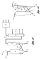
- Figure 1a is a schematic diagram of a fluid catalytic cracking unit
- Figure 1b is a schematic diagram of a reactor and a regenerator of the fluid catalytic cracking unit of Figure 1a ;
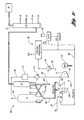
- Figure 1c is a schematic diagram of a fluid catalytic cracking unit in accordance with at least one embodiment of the present invention.
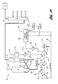
- Figure 1d is a schematic diagram of a fluid catalytic cracking unit in accordance with at least another embodiment of the present invention.
- Figure 2 is a flow chart of an example of a method of heating a fluid catalytic cracking in accordance with the present invention.
- Examples of the present invention seek to overcome some of the concerns associated with heating a fluid catalytic cracking unit while reducing overall CO 2 emissions from the refinery.
- a conventional fluid catalytic cracking unit burns coke from the spent catalyst by feeding gas comprising air and/or O 2 into the regenerator, producing flue gas, which contains CO 2 but is typically rich in nitrogen (N 2 ).
- a feed gas comprising O 2 with CO 2 and/or H 2 O may be produced.
- the CO 2 and the O 2 in the feed gas may react with the carbon-hydrogen based coke to produce CO 2 , CO, H 2 O and H 2 by a "dry” gasification process and the H 2 O and the O 2 in the feed gas may react with the coke to produce CO 2 , CO and H 2 by a "wet” gasification process.
- the H 2 in the syngas may be used as a raw material source for other operations within the refinery which may reduce the need for an additional fuel source, such as a hydrogen furnace. Additionally, the CO 2 in the syngas may be more easily sequestered than CO 2 in N 2 rich flue gas, such as for example, by limestone structures or any other suitable means known to those skilled in the art. By reducing or eliminating the need for a hydrogen furnace and by sequestering the CO 2 for recycling as a feed gas for operating the regenerator at gasification conditions, overall CO 2 emission may be reduced from the refinery.
- burning coke on spent catalyst under gasification conditions is not as exothermic a process as burning coke in air and/or O 2 .
- the coke fuel is typically limited because only about 4%, for example, of a VGO feedstock fed to the reactor is converted to coke which is deposited upon the catalyst. Accordingly, less heat is generated under gasification conditions and since the heat generated in the regenerator is recovered by the reactor for the cracking reaction, the reactor may be at a lower temperature which could adversely affect cracking of the hydrocarbon feedstock. Applicant has discovered that by introducing a high Conradson carbon feedstock into the reactor, a "coke heavy" spent catalyst may be generated which provides more fuel to the regenerator and thus, more heat is produced to support the operation of the reactor at reaction temperatures.
- a vacuum residue feedstock is fed into the reactor producing the coke heavy spent catalyst.
- a solvent deasphalter pitch (SDA pitch) is fed into the reactor to produce the coke heavy spent catalyst.
- Vacuum residue is defined herein as a low value hydrocarbon fraction of crude which is rich in asphaltenes and heavy Conradson carbon e.g. 18 to 30 or more.
- SDA pitch is defined herein as being that portion of the vacuum residue that is insoluble in a paraffinic solvent. SDA pitch contains the majority of the vacuum residue's asphaltenes and Conradson carbon and is therefore very rich in carbon.
- Coke heavy spent catalyst is defined herein as being catalyst having at least about 12 percent by weight of the crude that is fed to the reactor being converted to coke which is deposited onto the catalyst.
- the significantly higher coke content provides additional fuel.
- the additional fuel/coke generates more heat when it is burned and thus, allows the reactor to operate at reaction temperatures for cracking the feedstock.
- FIG. 1 a illustrates a fluid catalytic cracking (FCC) unit and separation system 10.
- the FCC unit 10 comprises a reactor 12 that is configured to receive crude or a hydrocarbon feedstock 30 (fresh feed) and a regenerator 14 in fluid communication with the reactor 12 to receive spent catalyst.
- the reactor 12 cracks the feedstock 30 therein to an effluent containing hydrocarbons ranging from methane through relatively high boiling point materials along with H 2 and H 2 S.
- a carbonaceous by-product is deposited on the circulating catalyst. This material, termed "coke,” is continuously burned off the spent catalyst in the regenerator 14 as will be mentioned below.
- the FCC unit 10 comprises the regenerator 14 for regenerating spent catalyst from the reactor 12.
- the regenerator 14 is configured to receive a feed gas 22 from an outside source and spent catalyst from the reactor 12. From the reactor 12, the spent catalyst has coke deposited thereon, reducing the activity of the catalyst.
- the regenerator 14 receives the feed gas 22 to burn the coke off the spent catalyst, thereby producing a flue gas 26 that exits a flue gas line 28 to a flue-gas system.
- the flue gas 26 may comprise CO, CO 2 , H 2 O (steam), SO x and N 2 , but it is typically very rich in N 2
- the regenerator 14 is configured to rejuvenate or reactivate the spent catalyst by burning the deposited coke off the spent catalyst with the feed gas 22.
- the regenerator 14 reactivates the catalyst so that, when returned to the reactor 12, the catalyst is in optimum condition to perform its cracking function.
- the regenerator 14 serves to gasify the coke from the catalyst particles and, at the same time, to impart sensible heat to the circulating catalyst.
- the energy carried by the hot regenerator catalyst is used to satisfy the thermal requirements for the reactor 12 of the FCC unit 10.
- the FCC unit 10 may have a number of optional units associated with the flue-gas system.
- the flue gas 26 may comprise catalyst fines, N 2 from air used for combustion, products of coke combustions (e.g., oxides of carbon, sulfur, nitrogen, and water vapor), and trace quantities of other compounds.
- the flue gas 26 exits the regenerator 14 at a temperature of approximately 1325 degrees Fahrenheit (F), but may be as high as 1400 degrees F or as low as 1200 degrees F, and at pressures of between about 20 and 50 pounds per square inch gauge (psig).
- the thermal and kinetic energy of the flue gas 26 can be converted to steam or used to drive a turbo-expander generator system for electrical power generation.
- Unconverted CO in the flue gas 26 can be combusted to CO 2 in a CO boiler with production of high-pressure steam. Catalyst fines may be removed by a solid removal unit, such as for example, an electrostatic precipitator. CO 2 from the regenerator and/or CO boiler is released to the atmosphere.
- a solid removal unit such as for example, an electrostatic precipitator.
- hot regenerated catalyst is fed back to the reactor 12 via reactivated catalyst return line 20 and vaporizes the hydrocarbon feedstock 30 to define resultant vapors.
- the resultant vapors carry the catalyst upward through a riser 16 of the reactor 12 with a minimum of back mixing.
- desired cracking reactions have been completed and the catalyst is quickly separated from the hydrocarbon vapors to minimize secondary reactions.
- the catalyst-hydrocarbon mixture from the riser 16 is discharged into the reactor 12 vessel through a separation device 18, e.g., a riser termination device, achieving a substantial degree of catalyst-gas separation, e.g., at least 90 weight percent product vapor separation from catalyst.
- a final separation of catalyst and product vapor may be accomplished by cyclone separation.
- the reactor effluent is directed to a main fractionator or fractionation column 50 of the unit 10 for resolution into gaseous light olefin co-products, FCC gasoline, and cycle stocks.
- the spent catalyst drops from within the reactor 12 vessel into a stripping section 24 thereof, where a countercurrent flow of steam removes interstitial and some adsorbed hydrocarbon vapors, defining stripped spent catalyst. Stripped spent catalyst descends through a first standpipe 23 and into the regenerator 14.
- fresh catalyst may be introduced into the circulating-catalyst system by any suitable manner. For example, this may be accomplished by way of a catalyst storage hopper (not shown). Moreover, an additional storage hopper (not shown) may be used to hold spent catalyst withdrawn from the circulating system as necessary to maintain the desired working activity and to hold all catalyst inventory when the FCC unit 10 is shut down for maintenance and repairs.
- fresh feedstock 30 and (depending on product-distribution objectives) recycled cycle oils are introduced into the bottom of the riser 16 together with a controlled amount of regenerated catalyst.
- the charge may be preheated, either by heat exchange or, for some applications, by means of a fired heater.
- Feedstocks 30 for the FCC process include mixtures of hydrocarbons of various types, including relatively small molecules such as found in gasoline to large molecules of 60 or more carbon atoms.
- the feedstock 30 may include a relatively small content of contaminant materials such as organic sulfur, nitrogen compounds, and organometallic compounds. It is to be noted that the relative proportions of all such materials will vary with the geographic origin of the crude and the particular boiling range of the FCC feedstock 30. However, the feedstocks 30 may be ranked in terms of their "crackabilities," or the ease with which they can be converted in an FCC unit. Crackability may be defined by a function of the relative proportions of paraffinic, naphthenic, and aromatic species in the feed.
- the FCC unit 10 further includes a main-fractionation column 50 through which the reactor effluent is separated into various products.
- the main-fractionation comprises an overhead line 52, a first side cut line 54, a second side line 56, a third side cut line 58, and a bottom line 60.
- the overhead line 52 includes gasoline and lighter material
- the first side cut line 54 includes naphtha
- the second side cut line 56 includes light cycle oil
- the third side cut line 58 includes heavy cycle oil
- the bottom line 60 includes slurry oil.
- the lines may include other products without falling beyond the scope or spirit of the present invention.
- Reactor-product vapors are directed to the main fractionator 50 at which gasoline and gaseous olefin-rich co-products are taken overhead and routed to a gas-concentration unit 70.
- main-fractionator 50 At the main-fractionator 50, light-cycle oil is recovered as a side cut with the net yield of this material being stripped for removal of light ends and sent to storage. Net column bottoms are yielded as slurry or clarified oil. Because of the high efficiency of the catalyst-hydrocarbon separation system utilized in the reactor design, catalyst carry-over to the fractionator 50 is minimized and it is not necessary to clarify the net heavy product yielded from the bottom of the fractionator 50 unless the material is to be used in some specific application requiring low solids content such as the production of carbon black. In some instances, heavy material can be recycled to the reactor riser 16.
- the gas-concentration column 70 is in fluid communication with overhead line of the main-fractionation column 50. From the overhead line 52, the gas-concentration column 50 receives unstable gasoline and lighter products that are separated therethrough into fuel gas for alkylation, polymerization, and debutanized gasoline.
- the gas-concentration section 70 may be one or an assembly of absorbers and fractionators that separate the main-column overhead into gasoline and other desired light products. Olefinic gases from other processes such as coking may be also sent to the FCC gas-concentration section.
- the gas-concentration unit may have one or a plurality of columns.
- the gas-concentration unit may be a "four-column" gas-concentration plant comprising a primary absorber, a secondary absorber, a stripper, and a debutanizer.
- the system 80 comprises a compressor 82 for compressing syngas 84 at an inlet pressure to a predetermined high pressure to define a compressed syngas 85.
- the syngas 84 is comprised of CO 2 , CO, H 2 O and COS and may further include H 2 and H 2 S.
- the compressor 82 has a compression ratio between about 5:1 and 10:1 and preferably has a compression ratio of about 7:1.
- the inlet pressure may be, for example, between about 25 and 35 psig.
- the compressor 82 preferably compresses the syngas 84 to a pressure between about 150 and 500 psig.
- a separator unit 86 is in fluid communication with the compressor 82.
- the separator unit 86 is configured to separate at least CO 2 from the compressed syngas 85 to produce a first stream of gas 88 comprising CO 2 .
- the separator unit uses a wet gas scrubbing process such as amine absorption, Rectisol TM , or Selexol TM , which is used to remove and/or separate H 2 S, COS, and CO 2 from the compressed syngas 85 to produce the first stream of gas 88.
- a wet gas scrubbing process such as amine absorption, Rectisol TM , or Selexol TM , which is used to remove and/or separate H 2 S, COS, and CO 2 from the compressed syngas 85 to produce the first stream of gas 88.
- Other suitable forms of separating known to those skilled in the art may also be used.
- the syngas gas 85 may also contain CO and H 2 , which can be mixed with steam and sent to a water-gas shift reactor to convert CO to CO 2 , thus producing additional H 2 .
- the H 2 may be further separated from the CO 2 via a process known as pressure swing adsorption.
- the separated H 2 72 may minimize the need to burn hydrocarbon fuels elsewhere in the plant for use by another system, thereby reducing overall CO 2 emissions from the refinery.
- the separated H 2 72 may be used by another system by being burned as a fuel or used to hydro-treat or hydrocrack other hydrocarbons.
- Heat recovery and cooling by a cooling unit 90 may be performed subsequent to compressing the syngas 84 by the compressor 82 but prior to the compressed syngas 85 being processed by the separation unit 86.
- the cooling unit 90 cools the compressed syngas 85 having a temperature between about 600 and 800 degrees F to between about 300 and 500 degrees F.
- the first stream of gas 88 which may contain a portion of the separated CO plus H 2 that is in excess of the amount required for refinery H 2 production, is supplied to an expander 100 which is in fluid communication with the separator unit 86.
- a second stream of gas 96 comprising O 2 may also be supplied to the expander 100.
- the first stream of gas 88 may initially be supplied to a combustion zone 92 or combustor with the second stream of gas 96. In this scenario, the combustion zone 92 is in direct fluid communication with the separator unit 86.
- the first stream of gas 88 may be supplied initially to a second compressor 94 which is in fluid communication with both the separator unit 86 and the combustion zone 92.
- the second compressor 94 further compresses the first stream of gas 88 prior to the combustion zone 92 receiving the gas 88.
- the combustion zone 92 is configured for combusting the second stream of gas 96 comprising O 2 with the first stream of gas 88 to a predetermined high temperature to produce heated gas 98. If the first stream of gas 88 contains any H 2 and/or CO, preferably the first and second streams of gas are combusted in the combustion zone 92 prior to being received by the expander 100. In one example, the predetermined high temperature is between about 1800 and 2100 degrees F. The combustion zone combusts any H 2 and/or CO from the first stream of gas 88 with the O 2 from the second stream of gas 96 to produce the heated gas 98 comprising CO 2 and/or H 2 O.
- some of the O 2 from the second stream of gas 96 will preferably remain un-reacted, especially if the second stream of gas is stoichiometrically in excess to the first stream of gas 88. In this scenario, the excess O 2 forms a portion of the heated gas 98.
- the expander 100 may be in direct fluid communication with the separator unit 86. Alternatively, the expander 100 may be in direct fluid communication with the combustion zone 92 and be in indirect fluid communication with the separator unit 86.
- the expander 100 is configured for expanding the first and second streams of gas 88 and 96 to a predetermined low pressure to define a feed gas 102. If the first and second streams of gas 88 and 96 are initially directed to the combustion zone 92, then the expander 100 expands these streams of gas 88 and 96 in the form of the heated gas 98.
- the expander 100 is a 10 to 15 stage turbo-expander.
- the feed gas 102 has a pressure between about 30 and 70 psig and preferably between about 30 and 40 psig and may have a temperature between about 1200 and 1600 degrees F when the combustion zone 92 is used. Alternatively, if the first and second streams of gas 88 and 96 are not combusted, the feed gas 102 may have a temperature of about 100 degrees F.
- the reactor 12 is configured for receiving a low value crude feed 104 rich in asphaltenes and Conradson carbon.
- the low value crude feed 104 is substantially vacuum residue.
- the low value crude feed 104 is substantially SDA pitch.
- the reactor 12 cracks the low value crude feed 104 with catalyst, producing coke heavy spent catalyst 106 which is advanced to the regenerator 14 via the first standpipe 23.
- the regenerator 14 receives the feed gas 102, which in one example comprises O 2 and CO 2 .
- the feed gas 102 may further include H 2 O.
- the regenerator 14 is operating at gasification conditions, burning coke from the coke heavy spent catalyst 106 with the feed gas 102.
- the additional coke deposited on the coke heavy spent catalyst 106 fuels the burning process and increases the combustion energy within the regenerator 14, enhancing the gasification process and producing syngas and heat.
- the syngas is preferably at a temperature between about 1200 and 1850 degrees F and may also be rich in CO and H 2 .
- the compressor 82, the combustion zone 92 and the expander 100 may be part of a turbo-expander train 110.
- the turbo-expander train 110 includes a shaft 112 operably coupled to both the expander 100 and the compressor 82 such that the expander 100 rotates the shaft 112 which drives the compressor 82.
- the expander 100 acting as a turbine engine, extracts energy from the heated gas 98 by expanding the heated gas 98.
- the expander 100 converts the extracted energy to rotational energy which rotates the shaft 112.
- the turbo-expander train 110 may further include a second compressor 94 which is operably coupled to the shaft 112 and is also driven by the expander 100.
- the system 80 may include a solid removal unit 114 and a cooling unit 116.
- the cooling unit 116 is in fluid communication with the solid removal unit 114 and the compressor 82.
- the solid removal unit 114 is in fluid communication with the regenerator 14 and may be used to remove catalyst fines from the syngas 84 prior to the syngas 84 being received by the cooling unit 116 and/or the compressor 82.
- the cooling unit 116 cools the syngas 84 from a temperature between about 1200 and 1850 degrees F, but preferably between about 1200 and 1400 degrees F, to a temperature between about 300 and 600 degrees F.
- the turbo-expander train 110 further includes a motor generator 118.
- the motor generator 118 is operably coupled to the shaft 112 and is driven by the expander 100.
- the motor generator 118 produces electrical power when the shaft 112 is rotated.
- the electrical power may be used for various processes within the plant. In one example, this electrical power minimizes the need to burn fuel elsewhere in the plant for power generation, thereby reducing overall CO 2 emissions from the refinery.
- At least one embodiment for a method of heating a fluid catalytic cracking unit having a regenerator and a reactor for overall carbon dioxide reduction comprises compressing syngas 120 at an inlet pressure to a predetermined high pressure to define compressed syngas.
- the inlet pressure is between about 25 and 35 psig and the predetermined high pressure is between about 150 and 500 psig.
- CO 2 is separated from the compressed syngas to provide a first stream of gas 122 comprising CO 2 .
- the first stream of gas is combusted with a second stream of gas comprising O 2 to produce heated gas.
- the heated gas may have a temperature between about 1800 and 2100 degrees F.
- the first and second streams of gas may be expanded 126 to a low pressure to define a feed gas.
- the expander expands the first and second streams of gas in the form of the heated gas.
- the feed gas is introduced to the regenerator 128.
- the regenerator is at gasification conditions to burn coke from coke heavy spent catalyst, which was advanced from the reactor. Burning of the coke produces the syngas and heat for operating the reactor at reaction temperatures.
- the feed gas has a temperature between about 1200 and 1600 degrees F and the syngas produced within the regenerator has a temperature between 1200 and 1850 degrees F and preferably between about 1200 and 1400 degrees F.
- the method further includes removing catalyst fines and cooling the syngas to a temperature between 400 and 600 degrees F prior to the step of compressing.
- the compressed syngas may also be cooled to a temperature between 300 and 500°F.
- this example calculates the total heat required by the reactor when a feedstock enters the riser at 450°F and the reactor product exits at 980°F.
- the total heat available in the regenerator is calculated with the regenerator operating at 1275°F and circulating 7 Ibs of catalyst per pound of FCC feedstock. Assuming the coke has an approximate formula of C 22 H 11 and contains an indistinguishable amount of sulfur, the example requires 13.75 Ibs of air (under combustion conditions) to burn each pound of coke. Based on these operating conditions and assumptions, the reactor has a total heat requirement of 620 Btu per Ib of feedstock. The regenerator, under combustion conditions, has a total heat available of 13,332 Btu per Ib of coke.
- the minimum amount of coke on catalyst to supply the required heat to the reactor is 0.047 Ib coke/Ib feedstock [(620 Btu/Ib of feedstock) / (13,332 Btu/Ib of coke)] or about 4.7%.
- this example shifts from combustion conditions to gasification conditions in the regenerator. If reactor conditions remain the same as Table 1 (i.e. feedstock entering at 450°F and product exiting at 980°F), then the total heat required by the reactor will remain the same (620 Btu per Ib of feedstock). Additionally, the regenerator will have to supply catalyst to the reactor at the same rate and temperature. Under gasification conditions, the total heat available can vary depending on the concentration of O 2 and CO 2 in the feed gas. In this example, assume the following reaction represents the heat of combustion based on one ratio of O 2 to CO 2 (C 22 H 11 + 81 ⁇ 2 O 2 + 5 CO 2 ⁇ 27 CO + 51 ⁇ 2H 2 ). This reaction produces approximately 2,711 Btu per Ib of coke.
- the regenerator under gasification conditions, has a total heat available of 1,885 Btu per Ib of coke.
- the minimum amount of coke on catalyst to supply the required heat to the reactor is 0.329 Ib coke/Ib feedstock [(620 Btu/Ib of feedstock) / (1,885 Btu/Ib of coke)] or about 32.9%.
- this increased coke level is not typically achieved during normal operations of the FCC unit e.g. a VGO feedstock produces only about 4% by weight of coke/feedstock.
- a coke heavy spent catalyst can be produced, which when burned within the regenerator may produce enough heat to satisfy the energy requirement of the reactor.
- the coke heavy spent catalyst burns to produce at least about a 600 BTU/Ib of the feedstock for operating the reactor at reaction temperatures. TABLE 2.
Landscapes
- Chemical & Material Sciences (AREA)
- Engineering & Computer Science (AREA)
- Chemical Kinetics & Catalysis (AREA)
- Organic Chemistry (AREA)
- Combustion & Propulsion (AREA)
- Mechanical Engineering (AREA)
- General Engineering & Computer Science (AREA)
- Materials Engineering (AREA)
- Oil, Petroleum & Natural Gas (AREA)
- General Chemical & Material Sciences (AREA)
- Production Of Liquid Hydrocarbon Mixture For Refining Petroleum (AREA)
Abstract


Description
- This application claims the benefit of
U.S. Non-Provisional Application Serial no. 11/962,740, filed on December 21, 2007 - This application is the result of a joint research agreement between UOP LLC and BP Products North America Inc.
- The present invention relates to methods and systems of reducing carbon dioxide emissions in a fluid catalytic cracking unit.
- The fluidized catalytic cracking of hydrocarbons is the mainstay process for the production of gasoline and light hydrocarbon products from heavy hydrocarbon charge stocks such as vacuum gas oils (VGO) or residual feeds. Large hydrocarbon molecules associated with the heavy hydrocarbon feed are cracked to break the large hydrocarbon chains thereby producing lighter hydrocarbons. These lighter hydrocarbons are recovered as product and can be used directly or further processed to raise the octane barrel yield relative to the heavy hydrocarbon feed.
- The basic equipment or apparatus for the fluidized catalytic cracking (FCC) of hydrocarbons has been in existence since the early 1940's. The basic components of the FCC process include a reactor, a regenerator, and a catalyst stripper. The reactor includes a contact zone where the hydrocarbon feed is contacted with a particulate catalyst and a separation zone where product vapors from the cracking reaction are separated from the catalyst. Further product separation takes place in a catalyst stripper that receives catalyst from the separation zone and removes entrained hydrocarbons from the catalyst by countercurrent contact with steam or another stripping medium.
- The FCC process is carried out by contacting the starting material - generally VGO, reduced crude, or another source of relatively high boiling hydrocarbons - with a catalyst made up of a finely divided or particulate solid material. The catalyst is transported like a fluid by passing gas or vapor through it at sufficient velocity to produce a desired regime of fluid transport. Contact of the oil with the fluidized material catalyzes the cracking reaction. The cracking reaction deposits coke on the catalyst. Coke is comprised of hydrogen and carbon and can include other materials in trace quantities such as sulfur and metals that enter the process with the starting material. Coke interferes with the catalytic activity of the catalyst by blocking active sites on the catalyst surface where the cracking reactions take place. Catalyst is traditionally transferred from the stripper to a regenerator for purposes of removing the coke by oxidation with an oxygen-containing gas. An inventory of catalyst having a reduced coke content relative to the catalyst in the stripper, hereinafter referred to as regenerated catalyst, is collected for return to the reaction zone. Oxidizing the coke from the catalyst surface releases a large amount of heat, a portion of which escapes the regenerator with gaseous products of coke oxidation generally referred to as flue gas. The balance of the heat leaves the regenerator with the regenerated catalyst. The fluidized catalyst is continuously circulated from the reaction zone to the regeneration zone and then again to the reaction zone. The fluidized catalyst, as well as providing a catalytic function, acts as a vehicle for the transfer of heat from zone to zone. Catalyst exiting the reaction zone is spoken of as being spent, i.e., partially deactivated by the deposition of coke upon the catalyst. Specific details of the various contact zones, regeneration zones, and stripping zones along with arrangements for conveying the catalyst between the various zones are well known to those skilled in the art.
- Refining companies are under increased pressure to reduce CO2 emissions as a result of carbon tax legislation and other drivers such as a desire to demonstrate long-term sustainability. Thus, there is a need to provide a way to reduce the carbon dioxide emissions of a fluid catalytic cracking unit.
- One solution to reducing carbon dioxide emissions involves operating the FCC regenerator at gasification conditions and supplying the regenerator with a feed comprising recycled carbon dioxide and oxygen. In this scenario, carbon dioxide is reduced in part because the carbon dioxide is being recycled from a synthesis gas separator unit. One issue with this solution, however, is that under gasification conditions, the regenerator may not supply enough heat to the FCC reactor for cracking the hydrocarbon feedstock with the catalyst.
- Embodiments of the present invention generally provide methods and systems of heating a fluid catalytic cracking unit having a reactor and a regenerator operating at gasification conditions for overall carbon dioxide reduction. The methods and systems of the present invention provide solutions to generating sufficient heat for operating the reactor at reaction temperature.
- In at least one embodiment, a method of heating a fluid catalytic cracking unit having a regenerator and a reactor for overall carbon dioxide reduction is provided. The method comprises compressing syngas at an inlet pressure to a predetermined high pressure to define compressed syngas. The syngas comprises carbon dioxide (CO2), carbon monoxide (CO), water (H2O), hydrogen sulfide (H2S) and carbonyl sulfide (COS). A first stream of gas comprising CO2 is separated from the compressed syngas. The first stream of gas is expanded with a second stream of gas comprising oxygen (O2) to a predetermined low pressure to define a feed gas. The feed gas is introduced to the regenerator at gasification conditions to burn coke from coke heavy spent catalyst advanced from the reactor. Burning of the coke produces the syngas and heat for operating the reactor at reaction temperatures.
- In one aspect of the present invention, the method further comprises providing a turbo-expander train including a first compressor, an expander, and a shaft operatively coupled to both the first compressor and the expander such that the expander rotates the shaft which drives the first compressor. The syngas is compressed by the first compressor to define the compressed syngas. The expander expands the first stream of gas with the second stream of gas to produce the feed gas and to extract energy from the first and second streams of gas to drive the expander to rotate the shaft.
- In at least one other embodiment of the present invention, a system for heating a fluid catalytic cracking unit having a regenerator and a reactor for overall reduction of carbon dioxide reduction is provided. The system comprises a compressor for compressing syngas at an inlet pressure to a predetermined high pressure to define compressed syngas. The syngas comprises CO2, CO, H2O, H2S and COS. In fluid communication with the compressor is a separator unit. The separator unit is configured to separate a first stream of gas comprising CO2 from the compressed syngas. An expander is in fluid communication with the separator unit. The expander is configured for expanding the first stream of gas with a second stream of gas comprising O2 to define a feed gas. At gasification conditions is the regenerator for regenerating coke heavy spent catalyst from the reactor. The regenerator is configured for receiving the feed gas to burn coke from the coke heavy spent catalyst, producing the syngas and heat for operating the reactor at reaction temperatures.
- Further objects, features and advantages of the invention will become apparent from consideration from the following description and the appended claims when taken in connection with the accompanying drawings.
-
Figure 1a is a schematic diagram of a fluid catalytic cracking unit; -
Figure 1b is a schematic diagram of a reactor and a regenerator of the fluid catalytic cracking unit ofFigure 1a ; -
Figure 1c is a schematic diagram of a fluid catalytic cracking unit in accordance with at least one embodiment of the present invention; -
Figure 1d is a schematic diagram of a fluid catalytic cracking unit in accordance with at least another embodiment of the present invention; and -
Figure 2 is a flow chart of an example of a method of heating a fluid catalytic cracking in accordance with the present invention. - Detailed embodiments of the present invention are disclosed herein. It is understood however, that the disclosed embodiments are merely exemplary of the invention that may be embodied in various and alternative forms. The figures are not necessarily to scale; some figures may be configured to show the details of a particular component. Therefore, specific structural and functional details disclosed herein are not interpreted as limiting but merely as a representative basis with the claims and for teaching one skilled in the art to practice the present invention.
- Examples of the present invention seek to overcome some of the concerns associated with heating a fluid catalytic cracking unit while reducing overall CO2 emissions from the refinery. A conventional fluid catalytic cracking unit burns coke from the spent catalyst by feeding gas comprising air and/or O2 into the regenerator, producing flue gas, which contains CO2 but is typically rich in nitrogen (N2). However, by introducing a feed gas comprising O2 with CO2 and/or H2O into the regenerator, a synthesis gas (syngas) may be produced. Specifically, the CO2 and the O2 in the feed gas may react with the carbon-hydrogen based coke to produce CO2, CO, H2O and H2 by a "dry" gasification process and the H2O and the O2 in the feed gas may react with the coke to produce CO2, CO and H2 by a "wet" gasification process.
- The H2 in the syngas may be used as a raw material source for other operations within the refinery which may reduce the need for an additional fuel source, such as a hydrogen furnace. Additionally, the CO2 in the syngas may be more easily sequestered than CO2 in N2 rich flue gas, such as for example, by limestone structures or any other suitable means known to those skilled in the art. By reducing or eliminating the need for a hydrogen furnace and by sequestering the CO2 for recycling as a feed gas for operating the regenerator at gasification conditions, overall CO2 emission may be reduced from the refinery.
- However, burning coke on spent catalyst under gasification conditions is not as exothermic a process as burning coke in air and/or O2. Moreover, the coke fuel is typically limited because only about 4%, for example, of a VGO feedstock fed to the reactor is converted to coke which is deposited upon the catalyst.
Accordingly, less heat is generated under gasification conditions and since the heat generated in the regenerator is recovered by the reactor for the cracking reaction, the reactor may be at a lower temperature which could adversely affect cracking of the hydrocarbon feedstock. Applicant has discovered that by introducing a high Conradson carbon feedstock into the reactor, a "coke heavy" spent catalyst may be generated which provides more fuel to the regenerator and thus, more heat is produced to support the operation of the reactor at reaction temperatures. In one example, a vacuum residue feedstock is fed into the reactor producing the coke heavy spent catalyst. In an alternative example, a solvent deasphalter pitch (SDA pitch) is fed into the reactor to produce the coke heavy spent catalyst. Vacuum residue is defined herein as a low value hydrocarbon fraction of crude which is rich in asphaltenes and heavy Conradson carbon e.g. 18 to 30 or more. SDA pitch is defined herein as being that portion of the vacuum residue that is insoluble in a paraffinic solvent. SDA pitch contains the majority of the vacuum residue's asphaltenes and Conradson carbon and is therefore very rich in carbon. Coke heavy spent catalyst is defined herein as being catalyst having at least about 12 percent by weight of the crude that is fed to the reactor being converted to coke which is deposited onto the catalyst. When the coke heavy spent catalyst is regenerated in the regenerator, the significantly higher coke content provides additional fuel. The additional fuel/coke generates more heat when it is burned and thus, allows the reactor to operate at reaction temperatures for cracking the feedstock. - Referring now to the drawings,
Figure 1 a illustrates a fluid catalytic cracking (FCC) unit andseparation system 10. As shown, theFCC unit 10 comprises areactor 12 that is configured to receive crude or a hydrocarbon feedstock 30 (fresh feed) and aregenerator 14 in fluid communication with thereactor 12 to receive spent catalyst. Thereactor 12 cracks thefeedstock 30 therein to an effluent containing hydrocarbons ranging from methane through relatively high boiling point materials along with H2 and H2S. During the cracking reaction, a carbonaceous by-product is deposited on the circulating catalyst. This material, termed "coke," is continuously burned off the spent catalyst in theregenerator 14 as will be mentioned below. - The
FCC unit 10 comprises theregenerator 14 for regenerating spent catalyst from thereactor 12. Theregenerator 14 is configured to receive afeed gas 22 from an outside source and spent catalyst from thereactor 12. From thereactor 12, the spent catalyst has coke deposited thereon, reducing the activity of the catalyst. Theregenerator 14 receives thefeed gas 22 to burn the coke off the spent catalyst, thereby producing aflue gas 26 that exits aflue gas line 28 to a flue-gas system. Theflue gas 26 may comprise CO, CO2, H2O (steam), SOx and N2, but it is typically very rich in N2 Theregenerator 14 is configured to rejuvenate or reactivate the spent catalyst by burning the deposited coke off the spent catalyst with thefeed gas 22. - The
regenerator 14 reactivates the catalyst so that, when returned to thereactor 12, the catalyst is in optimum condition to perform its cracking function. Theregenerator 14 serves to gasify the coke from the catalyst particles and, at the same time, to impart sensible heat to the circulating catalyst. The energy carried by the hot regenerator catalyst is used to satisfy the thermal requirements for thereactor 12 of theFCC unit 10. - It is to be noted that the
FCC unit 10 may have a number of optional units associated with the flue-gas system. In one embodiment, theflue gas 26 may comprise catalyst fines, N2 from air used for combustion, products of coke combustions (e.g., oxides of carbon, sulfur, nitrogen, and water vapor), and trace quantities of other compounds. Theflue gas 26 exits theregenerator 14 at a temperature of approximately 1325 degrees Fahrenheit (F), but may be as high as 1400 degrees F or as low as 1200 degrees F, and at pressures of between about 20 and 50 pounds per square inch gauge (psig). The thermal and kinetic energy of theflue gas 26 can be converted to steam or used to drive a turbo-expander generator system for electrical power generation. Unconverted CO in theflue gas 26 can be combusted to CO2 in a CO boiler with production of high-pressure steam. Catalyst fines may be removed by a solid removal unit, such as for example, an electrostatic precipitator. CO2 from the regenerator and/or CO boiler is released to the atmosphere. - Referring now to
Figures 1 a to 1b, from theregenerator 14, hot regenerated catalyst is fed back to thereactor 12 via reactivatedcatalyst return line 20 and vaporizes thehydrocarbon feedstock 30 to define resultant vapors. The resultant vapors carry the catalyst upward through ariser 16 of thereactor 12 with a minimum of back mixing. At the top of theriser 16, desired cracking reactions have been completed and the catalyst is quickly separated from the hydrocarbon vapors to minimize secondary reactions. The catalyst-hydrocarbon mixture from theriser 16 is discharged into thereactor 12 vessel through aseparation device 18, e.g., a riser termination device, achieving a substantial degree of catalyst-gas separation, e.g., at least 90 weight percent product vapor separation from catalyst. A final separation of catalyst and product vapor may be accomplished by cyclone separation. - The reactor effluent is directed to a main fractionator or
fractionation column 50 of theunit 10 for resolution into gaseous light olefin co-products, FCC gasoline, and cycle stocks. The spent catalyst drops from within thereactor 12 vessel into a strippingsection 24 thereof, where a countercurrent flow of steam removes interstitial and some adsorbed hydrocarbon vapors, defining stripped spent catalyst. Stripped spent catalyst descends through afirst standpipe 23 and into theregenerator 14. - To maintain the activity of the working-catalyst inventory at a desired level and to make-up for any catalyst lost from the system with the
flue gas 26, fresh catalyst may be introduced into the circulating-catalyst system by any suitable manner. For example, this may be accomplished by way of a catalyst storage hopper (not shown). Moreover, an additional storage hopper (not shown) may be used to hold spent catalyst withdrawn from the circulating system as necessary to maintain the desired working activity and to hold all catalyst inventory when theFCC unit 10 is shut down for maintenance and repairs. - As shown in
Figures 1a and 1b , in the operation of theFCC unit 10,fresh feedstock 30 and (depending on product-distribution objectives) recycled cycle oils are introduced into the bottom of theriser 16 together with a controlled amount of regenerated catalyst. The charge may be preheated, either by heat exchange or, for some applications, by means of a fired heater. -
Feedstocks 30 for the FCC process include mixtures of hydrocarbons of various types, including relatively small molecules such as found in gasoline to large molecules of 60 or more carbon atoms. Thefeedstock 30 may include a relatively small content of contaminant materials such as organic sulfur, nitrogen compounds, and organometallic compounds. It is to be noted that the relative proportions of all such materials will vary with the geographic origin of the crude and the particular boiling range of theFCC feedstock 30. However, thefeedstocks 30 may be ranked in terms of their "crackabilities," or the ease with which they can be converted in an FCC unit. Crackability may be defined by a function of the relative proportions of paraffinic, naphthenic, and aromatic species in the feed. - The
FCC unit 10 further includes a main-fractionation column 50 through which the reactor effluent is separated into various products. The main-fractionation comprises anoverhead line 52, a first side cutline 54, asecond side line 56, a third side cutline 58, and abottom line 60. As shown, theoverhead line 52 includes gasoline and lighter material, the first side cutline 54 includes naphtha, the second side cutline 56 includes light cycle oil, the third side cutline 58 includes heavy cycle oil, and thebottom line 60 includes slurry oil. The lines may include other products without falling beyond the scope or spirit of the present invention. - Reactor-product vapors are directed to the
main fractionator 50 at which gasoline and gaseous olefin-rich co-products are taken overhead and routed to a gas-concentration unit 70. At the main-fractionator 50, light-cycle oil is recovered as a side cut with the net yield of this material being stripped for removal of light ends and sent to storage. Net column bottoms are yielded as slurry or clarified oil. Because of the high efficiency of the catalyst-hydrocarbon separation system utilized in the reactor design, catalyst carry-over to thefractionator 50 is minimized and it is not necessary to clarify the net heavy product yielded from the bottom of thefractionator 50 unless the material is to be used in some specific application requiring low solids content such as the production of carbon black. In some instances, heavy material can be recycled to thereactor riser 16. - Maximum usage is made of the heat available at the
main column 50. Typically, light-cycle and heavy-cycle oils are utilized in the gas-concentration section 70 for heat-exchange purposes, and steam is generated by circulating main-column bottoms stream. - The gas-
concentration column 70 is in fluid communication with overhead line of the main-fractionation column 50. From theoverhead line 52, the gas-concentration column 50 receives unstable gasoline and lighter products that are separated therethrough into fuel gas for alkylation, polymerization, and debutanized gasoline. - The gas-
concentration section 70 may be one or an assembly of absorbers and fractionators that separate the main-column overhead into gasoline and other desired light products. Olefinic gases from other processes such as coking may be also sent to the FCC gas-concentration section. The gas-concentration unit may have one or a plurality of columns. For example, the gas-concentration unit may be a "four-column" gas-concentration plant comprising a primary absorber, a secondary absorber, a stripper, and a debutanizer. - Referring now to
Figure 1c , at least one embodiment of asystem 80 for heating a fluid catalytic cracking unit that has aregenerator 14 and areactor 12 for overall carbon dioxide reduction is provided. Thesystem 80 comprises acompressor 82 for compressingsyngas 84 at an inlet pressure to a predetermined high pressure to define acompressed syngas 85. Thesyngas 84 is comprised of CO2, CO, H2O and COS and may further include H2 and H2S. In one example, thecompressor 82 has a compression ratio between about 5:1 and 10:1 and preferably has a compression ratio of about 7:1. The inlet pressure may be, for example, between about 25 and 35 psig. Thecompressor 82 preferably compresses thesyngas 84 to a pressure between about 150 and 500 psig. - A
separator unit 86 is in fluid communication with thecompressor 82. Theseparator unit 86 is configured to separate at least CO2 from the compressedsyngas 85 to produce a first stream ofgas 88 comprising CO2. In one example, the separator unit uses a wet gas scrubbing process such as amine absorption, Rectisol™, or Selexol™, which is used to remove and/or separate H2S, COS, and CO2 from the compressedsyngas 85 to produce the first stream ofgas 88. Other suitable forms of separating known to those skilled in the art may also be used. Thesyngas gas 85 may also contain CO and H2, which can be mixed with steam and sent to a water-gas shift reactor to convert CO to CO2, thus producing additional H2. The H2 may be further separated from the CO2 via a process known as pressure swing adsorption. In this scenario, the separatedH 2 72 may minimize the need to burn hydrocarbon fuels elsewhere in the plant for use by another system, thereby reducing overall CO2 emissions from the refinery. For example, the separatedH 2 72 may be used by another system by being burned as a fuel or used to hydro-treat or hydrocrack other hydrocarbons. - Heat recovery and cooling by a cooling
unit 90 may be performed subsequent to compressing thesyngas 84 by thecompressor 82 but prior to the compressedsyngas 85 being processed by theseparation unit 86. In one example, the coolingunit 90 cools the compressedsyngas 85 having a temperature between about 600 and 800 degrees F to between about 300 and 500 degrees F. - In one embodiment, the first stream of
gas 88, which may contain a portion of the separated CO plus H2 that is in excess of the amount required for refinery H2 production, is supplied to anexpander 100 which is in fluid communication with theseparator unit 86. A second stream ofgas 96 comprising O2 may also be supplied to theexpander 100. Alternatively and as illustrated inFigure 1c , the first stream ofgas 88 may initially be supplied to acombustion zone 92 or combustor with the second stream ofgas 96. In this scenario, thecombustion zone 92 is in direct fluid communication with theseparator unit 86. In still yet another example and as illustrated inFigure 1d , the first stream ofgas 88 may be supplied initially to asecond compressor 94 which is in fluid communication with both theseparator unit 86 and thecombustion zone 92. Thesecond compressor 94 further compresses the first stream ofgas 88 prior to thecombustion zone 92 receiving thegas 88. - The
combustion zone 92 is configured for combusting the second stream ofgas 96 comprising O2 with the first stream ofgas 88 to a predetermined high temperature to produceheated gas 98. If the first stream ofgas 88 contains any H2 and/or CO, preferably the first and second streams of gas are combusted in thecombustion zone 92 prior to being received by theexpander 100. In one example, the predetermined high temperature is between about 1800 and 2100 degrees F. The combustion zone combusts any H2 and/or CO from the first stream ofgas 88 with the O2 from the second stream ofgas 96 to produce theheated gas 98 comprising CO2 and/or H2O. Moreover, some of the O2 from the second stream ofgas 96 will preferably remain un-reacted, especially if the second stream of gas is stoichiometrically in excess to the first stream ofgas 88. In this scenario, the excess O2 forms a portion of theheated gas 98. - The
expander 100 may be in direct fluid communication with theseparator unit 86. Alternatively, theexpander 100 may be in direct fluid communication with thecombustion zone 92 and be in indirect fluid communication with theseparator unit 86. Theexpander 100 is configured for expanding the first and second streams ofgas feed gas 102. If the first and second streams ofgas combustion zone 92, then theexpander 100 expands these streams ofgas heated gas 98. In one embodiment, theexpander 100 is a 10 to 15 stage turbo-expander. Thefeed gas 102 has a pressure between about 30 and 70 psig and preferably between about 30 and 40 psig and may have a temperature between about 1200 and 1600 degrees F when thecombustion zone 92 is used. Alternatively, if the first and second streams ofgas feed gas 102 may have a temperature of about 100 degrees F. - In at least one embodiment, the
reactor 12 is configured for receiving a low valuecrude feed 104 rich in asphaltenes and Conradson carbon. In one example, the low valuecrude feed 104 is substantially vacuum residue. In another example, the low valuecrude feed 104 is substantially SDA pitch. - The
reactor 12 cracks the low valuecrude feed 104 with catalyst, producing coke heavy spentcatalyst 106 which is advanced to theregenerator 14 via thefirst standpipe 23. Preferably at least about, with increasing preference in the order given, 12%, 14%, 16%, 18% and 20% by weight of the low valuecrude feed 104 is converted to coke which is deposited onto the catalyst to form the coke heavy spentcatalyst 106. - The
regenerator 14 receives thefeed gas 102, which in one example comprises O2 and CO2. Thefeed gas 102 may further include H2O. Theregenerator 14 is operating at gasification conditions, burning coke from the coke heavy spentcatalyst 106 with thefeed gas 102. The additional coke deposited on the coke heavy spentcatalyst 106 fuels the burning process and increases the combustion energy within theregenerator 14, enhancing the gasification process and producing syngas and heat. The syngas is preferably at a temperature between about 1200 and 1850 degrees F and may also be rich in CO and H2. - Referring to
Figures 1c and1d , thecompressor 82, thecombustion zone 92 and theexpander 100 may be part of a turbo-expander train 110. The turbo-expander train 110 includes ashaft 112 operably coupled to both theexpander 100 and thecompressor 82 such that theexpander 100 rotates theshaft 112 which drives thecompressor 82. Theexpander 100, acting as a turbine engine, extracts energy from theheated gas 98 by expanding theheated gas 98. Theexpander 100 converts the extracted energy to rotational energy which rotates theshaft 112. In another example, the turbo-expander train 110 may further include asecond compressor 94 which is operably coupled to theshaft 112 and is also driven by theexpander 100. - The
system 80 may include asolid removal unit 114 and acooling unit 116. Thecooling unit 116 is in fluid communication with thesolid removal unit 114 and thecompressor 82. Thesolid removal unit 114 is in fluid communication with theregenerator 14 and may be used to remove catalyst fines from thesyngas 84 prior to thesyngas 84 being received by thecooling unit 116 and/or thecompressor 82. In one example, thecooling unit 116 cools thesyngas 84 from a temperature between about 1200 and 1850 degrees F, but preferably between about 1200 and 1400 degrees F, to a temperature between about 300 and 600 degrees F. - In at least one other embodiment, the turbo-
expander train 110 further includes amotor generator 118. Themotor generator 118 is operably coupled to theshaft 112 and is driven by theexpander 100. Themotor generator 118 produces electrical power when theshaft 112 is rotated. The electrical power may be used for various processes within the plant. In one example, this electrical power minimizes the need to burn fuel elsewhere in the plant for power generation, thereby reducing overall CO2 emissions from the refinery. - Referring to
Figure 2 , at least one embodiment for a method of heating a fluid catalytic cracking unit having a regenerator and a reactor for overall carbon dioxide reduction is provided. The method comprises compressingsyngas 120 at an inlet pressure to a predetermined high pressure to define compressed syngas. In one example, the inlet pressure is between about 25 and 35 psig and the predetermined high pressure is between about 150 and 500 psig. - CO2 is separated from the compressed syngas to provide a first stream of
gas 122 comprising CO2. In one example, the first stream of gas is combusted with a second stream of gas comprising O2 to produce heated gas. The heated gas may have a temperature between about 1800 and 2100 degrees F. - The first and second streams of gas may be expanded 126 to a low pressure to define a feed gas. In the example where the first and second streams of gas are combusted, the expander expands the first and second streams of gas in the form of the heated gas.
- The feed gas is introduced to the regenerator 128. The regenerator is at gasification conditions to burn coke from coke heavy spent catalyst, which was advanced from the reactor. Burning of the coke produces the syngas and heat for operating the reactor at reaction temperatures. In one example, the feed gas has a temperature between about 1200 and 1600 degrees F and the syngas produced within the regenerator has a temperature between 1200 and 1850 degrees F and preferably between about 1200 and 1400 degrees F.
- In at least one other embodiment, the method further includes removing catalyst fines and cooling the syngas to a temperature between 400 and 600 degrees F prior to the step of compressing. The compressed syngas may also be cooled to a temperature between 300 and 500°F.
- The following example (displayed in Tables 1 and 2) further illustrates embodiments of the invention. A comparison is made between: (1) a FCC unit with a reactor and a regenerator operating under combustion conditions (i.e. using air as the feed gas to the regenerator) and (2) a FCC unit with a reactor and a regenerator operating under gasification conditions (i.e. using an artificially created feed gas comprising CO2 and O2). Under normal FCC operations, the heat produced in the regenerator under combustion and gasification conditions ("total heat available") is transferred to operate the reactor ("total heat required").
- In Table 1, this example calculates the total heat required by the reactor when a feedstock enters the riser at 450°F and the reactor product exits at 980°F. The total heat available in the regenerator is calculated with the regenerator operating at 1275°F and circulating 7 Ibs of catalyst per pound of FCC feedstock. Assuming the coke has an approximate formula of C22H11 and contains an indistinguishable amount of sulfur, the example requires 13.75 Ibs of air (under combustion conditions) to burn each pound of coke. Based on these operating conditions and assumptions, the reactor has a total heat requirement of 620 Btu per Ib of feedstock. The regenerator, under combustion conditions, has a total heat available of 13,332 Btu per Ib of coke. Therefore, the minimum amount of coke on catalyst to supply the required heat to the reactor is 0.047 Ib coke/Ib feedstock [(620 Btu/Ib of feedstock) / (13,332 Btu/Ib of coke)] or about 4.7%.
TABLE 1. FCC Unit Operating Under Combustion Conditions Reactor Regenerator Source Btu/Ib of feed Source Btu/Ib of coke ΔH Feed 475 ΔH Air/Flue Gas -3,452 ΔH Reaction 132 ΔH Combustion 16, 775 ΔH Steam 10 Heat Loss -255 Heat Loss 3 Total Heat Required 620 Total Heat Available 13,332 Coke = Total Heat Required/Total Heat Available = 620/13332 * 100% = 4.7% - In Table 2, this example shifts from combustion conditions to gasification conditions in the regenerator. If reactor conditions remain the same as Table 1 (i.e. feedstock entering at 450°F and product exiting at 980°F), then the total heat required by the reactor will remain the same (620 Btu per Ib of feedstock). Additionally, the regenerator will have to supply catalyst to the reactor at the same rate and temperature. Under gasification conditions, the total heat available can vary depending on the concentration of O2 and CO2 in the feed gas. In this example, assume the following reaction represents the heat of combustion based on one ratio of O2 to CO2 (C22H11 + 8½ O2 + 5 CO2 → 27 CO + 5½H2). This reaction produces approximately 2,711 Btu per Ib of coke. Assuming that the incoming feed gas must be heated from 100°F to 1275°F, the heat requirement is approximately 571 Btu per Ib of coke ((1.8 Ib gas per Ib coke * 0.27 Btu per Ib °F * (1275°F-100°F)). The regenerator, under gasification conditions, has a total heat available of 1,885 Btu per Ib of coke. In this example, the minimum amount of coke on catalyst to supply the required heat to the reactor is 0.329 Ib coke/Ib feedstock [(620 Btu/Ib of feedstock) / (1,885 Btu/Ib of coke)] or about 32.9%. As discussed, this increased coke level is not typically achieved during normal operations of the FCC unit e.g. a VGO feedstock produces only about 4% by weight of coke/feedstock. However, by introducing a high Conradson carbon feedstock into the reactor a coke heavy spent catalyst can be produced, which when burned within the regenerator may produce enough heat to satisfy the energy requirement of the reactor. In one example, the coke heavy spent catalyst burns to produce at least about a 600 BTU/Ib of the feedstock for operating the reactor at reaction temperatures.
TABLE 2. FCC Unit Operating Under Gasification Conditions Reactor Regenerator Source Btu/Ib of feed Source Btu/Ib of coke ΔH Feed 475 ΔH Feed Gas/Syngas -571 ΔH Reaction 132 ΔH Combustion 2,711 ΔH Steam 10 Heat Loss -255 Heat Loss 3 Total Heat Required 620 Total Heat Available 1,885 Coke = Total Heat Required/Total Heat Available = 620/1885 * 100% = 32.9% - As a person skilled in the art will readily appreciate, the above description is meant as an illustration of the implementation of the principles of this invention. This description is not intended to limit the scope or application of the invention in that the invention is susceptible to modification, variation and change without departing from the spirit of this invention, as defined in the following claims.
Claims (25)
- A method of heating a fluid catalytic cracking unit having a regenerator and a reactor for overall carbon dioxide reduction, the method comprising:compressing syngas comprising CO2, CO, H2O, H2S and COS at an inlet pressure to a predetermined high pressure to define compressed syngas;separating a first stream of gas comprising CO2 from the compressed syngas;expanding the first stream of gas with a second stream of gas comprising O2 to a predetermined low pressure to define a feed gas; andintroducing the feed gas to the regenerator having coke heavy spent catalyst from the reactor, the regenerator at gasification conditions to burn coke from the coke heavy spent catalyst, producing the syngas and heat for operating the reactor at reaction temperatures.
- The method according to claim 1 wherein the reactor is configured for receiving feedstock that reacts with catalyst to produce the coke heavy spent catalyst and the heat for operating the reactor at reaction temperatures is at least about 600 BTU per pound of the feedstock.
- The method according to claim 2 wherein the feedstock comprises vacuum residue and at least about 12 percent by weight of the vacuum residue is converted to the coke which is deposited onto the catalyst to produce the coke heavy spent catalyst.
- The method according to claim 2 or claim 3 wherein the feedstock comprises solvent deasphalter pitch and at least about 12 percent by weight of the solvent deasphalter pitch is converted to the coke which is deposited onto the catalyst to produce the coke heavy spent catalyst.
- The method according to any one of the preceding claims wherein the syngas further comprises H2 and the first stream of gas further comprises at least one of CO and H2 and the method further comprises combusting the first stream of gas with the second stream of gas to a predetermined high temperature to produce a heated gas, and the step of expanding includes expanding the heated gas to define the feed gas.
- The method according to claim 5 wherein the predetermined high temperature is between about 1800 and 2100 degrees Fahrenheit (F).
- The method according to claim 5 or 6 further comprising separating at least a portion of the H2 from the compressed syngas, the portion of the H2 being used for another system, reducing overall CO2 emissions.
- The method according to any one of the preceding claims wherein the predetermined high pressure is between about 150 and 500 psig.
- The method according to any one of the preceding claims wherein the predetermined low pressure is between about 30 and 70 psig.
- The method according to any one of the preceding claims wherein the feed gas has a temperature between about 1200 and 1600 degrees Fahrenheit (F).
- The method according to any one of the preceding claims wherein the syngas produced at the reactor has a temperature between about 1200 and 1850 degrees Fahrenheit (F).
- The method according to any one of the preceding claims wherein the feed gas comprises CO2, O2 and H2O.
- The method according to any one of the preceding claims further comprising removing catalyst fines and cooling the syngas to a temperature between about 300 and 600 degrees Fahrenheit (F) prior to the step of compressing.
- The method according to any one of the preceding claims further comprising cooling the compressed syngas to a temperature between about 300 and 500 degrees Fahrenheit (F).
- A method of heating a fluid catalytic cracking unit having a regenerator and a reactor for overall carbon dioxide reduction, the method comprising:providing a turbo-expander train including a first compressor, an expander, and a shaft operatively coupled to both the expander and the first compressor such that the expander rotates the shaft which drives the first compressor;compressing syngas comprising CO2, CO, H2O, H2S and COS at an inlet pressure with the first compressor to a predetermined high pressure to define compressed syngas;separating a first stream of gas comprising CO2 from the compressed syngas;expanding the first stream of gas with a second stream of gas comprising O2 by the expander to a predetermined low pressure, producing a feed gas and extracting energy from the first and second streams of gas to drive the expander to rotate the shaft; andintroducing the feed gas to the regenerator having coke heavy spent catalyst from the reactor, the regenerator at gasification conditions to burn coke from the coke heavy spent catalyst, producing the syngas and heat for operating the reactor at reaction temperatures.
- The method according to claim 15 wherein the turbo-expander train further includes a combustion zone in fluid communication with the expander and the first stream of gas further comprises at least one of CO and H2 and the method further comprises combusting the first and second streams of gas by the combustion zone to a predetermined high temperature to produce heated gas, and the step of expanding includes expanding the heated gas, producing the feed gas and extracting energy from the heated gas by the expander to drive the expander to rotate the shaft.
- The method according to claim 15 or 16 wherein the turbo-expander train further includes a second compressor in fluid communication with the combustion zone and operatively coupled to the shaft such that rotation of the shaft drives the second compressor, and the method further includes compressing the first stream of gas prior to the step of combusting.
- The method according to any one of claims 15 to 17 wherein the turbo-expander train further includes a motor generator operatively coupled to the shaft such that rotation of the shaft drives the motor generator, and the method further comprises driving the motor generator producing electrical energy.
- A system for heating a fluid catalytic cracking unit having a regenerator and a reactor for overall carbon dioxide reduction, the system comprising:a compressor for compressing syngas comprising CO2, CO, H2O, H2S and COS at an inlet pressure to a predetermined high pressure to define compressed syngas;a separator unit in fluid communication with the compressor and configured to separate a first stream of gas comprising CO2 from the compressed syngas;an expander in fluid communication with the separator unit and configured for expanding the first stream of gas with a second stream of gas comprising O2 to a predetermined low pressure to define a feed gas; andthe regenerator at gasification conditions for regenerating coke heavy spent catalyst from the reactor and configured for receiving the feed gas to burn coke from the coke heavy spent catalyst, producing the syngas and heat for operating the reactor at reaction temperatures.
- The system according to claim 19 wherein the compressor and the expander are part of a turbo-expander train, the turbo-expander train including a combustion zone in fluid communication with the separator unit and the expander, and a shaft operatively coupled to both the expander and the compressor such that the expander rotates the shaft which drives the first compressor, the combustion zone configured for combusting the first and second streams of gas to a predetermined high temperature to produce heated gas, and the expander configured for extracting energy from the heated gas, rotating the shaft.
- The system according to claim 19 or 20 wherein the predetermined high temperature is between about 1800 and 2100 degrees Fahrenheit (F) and the feed gas has a temperature between about 1200 and 1600 degrees Fahrenheit (F).
- The system according to any one of claims 19 to 21 further comprising the reactor configured for receiving feedstock, the feedstock comprising at least one of vacuum residue and solvent deasphalter pitch to produce the coke heavy spent catalyst.
- The system according to any one of claims 19 to 22 wherein the predetermined high pressure is between about 150 and 500 psig and the predetermined low pressure is between about 30 and 70 psig.
- The system according to any one of claims 19 to 23 wherein the syngas further comprises H2 and the separator unit is further configured to separate at least a portion of the H2 from the compressed syngas, the portion of the H2 being used for another system, reducing overall CO2 emissions.
- The system according to any one of claims 19 to 24 wherein the reactor is configured for receiving feedstock that reacts with catalyst to produce the coke heavy spent catalyst and the heat for operating the reactor at reaction temperatures is at least about 600 BTU per pound of feedstock.
Applications Claiming Priority (1)
| Application Number | Priority Date | Filing Date | Title |
|---|---|---|---|
| US11/962,740 US7699974B2 (en) | 2007-12-21 | 2007-12-21 | Method and system of heating a fluid catalytic cracking unit having a regenerator and a reactor |
Publications (1)
| Publication Number | Publication Date |
|---|---|
| EP2077309A1 true EP2077309A1 (en) | 2009-07-08 |
Family
ID=40551959
Family Applications (1)
| Application Number | Title | Priority Date | Filing Date |
|---|---|---|---|
| EP08254091A Withdrawn EP2077309A1 (en) | 2007-12-21 | 2008-12-19 | Method and system of heating a fluid catalytic cracking unit having a regenerator and a reactor |
Country Status (4)
| Country | Link |
|---|---|
| US (1) | US7699974B2 (en) |
| EP (1) | EP2077309A1 (en) |
| CN (1) | CN101497811A (en) |
| AU (1) | AU2008261146A1 (en) |
Families Citing this family (8)
| Publication number | Priority date | Publication date | Assignee | Title |
|---|---|---|---|---|
| US7811446B2 (en) * | 2007-12-21 | 2010-10-12 | Uop Llc | Method of recovering energy from a fluid catalytic cracking unit for overall carbon dioxide reduction |
| US7935245B2 (en) * | 2007-12-21 | 2011-05-03 | Uop Llc | System and method of increasing synthesis gas yield in a fluid catalytic cracking unit |
| BRPI0804120A2 (en) * | 2008-09-09 | 2010-07-06 | Petróleo Brasileiro S/A - Petrobras | method for the production of ethylene and synthesis gas in circulating fluidized bed |
| US9181496B2 (en) | 2012-03-23 | 2015-11-10 | Uop Llc | Process for modifying a fluid catalytic cracking unit, and an apparatus relating thereto |
| CN102614674B (en) * | 2012-03-29 | 2014-01-22 | 中国寰球工程公司 | System and method for discharging waste solvent of vacuum solvent evaporation type regenerator |
| EP3165585B1 (en) * | 2015-11-07 | 2018-07-18 | INDIAN OIL CORPORATION Ltd. | Process of upgradation of residual oil feedstock |
| CN109652104B (en) * | 2017-10-12 | 2021-02-09 | 中国石油化工股份有限公司 | Down bed-entrained flow bed pyrolysis-gasification integrated method and device |
| US11459515B2 (en) | 2020-10-02 | 2022-10-04 | Saudi Arabian Oil Company | Process for upgrading hydrocarbon feedstock utilizing low pressure hydroprocessing and catalyst rejuvenation/regeneration steps |
Citations (3)
| Publication number | Priority date | Publication date | Assignee | Title |
|---|---|---|---|---|
| EP0162251A1 (en) * | 1984-04-13 | 1985-11-27 | Air Products And Chemicals, Inc. | Process for the recovery and recycle of effluent gas from the regeneration of particulate matter with oxygen and carbon dioxide |
| EP1935966A1 (en) * | 2006-12-21 | 2008-06-25 | Uop Llc | System and method of reducing carbon dioxide emissions in a fluid catalytic cracking unit |
| EP1939269A1 (en) * | 2006-12-21 | 2008-07-02 | Uop Llc | Preheating process and apparatus for FCC regenerator |
Family Cites Families (82)
| Publication number | Priority date | Publication date | Assignee | Title |
|---|---|---|---|---|
| GB711208A (en) | 1949-10-04 | 1954-06-30 | Nat Res Dev | Improvements in or relating to the pyrolysis and/or cracking of organic substances |
| US2888395A (en) * | 1954-03-29 | 1959-05-26 | Universal Oil Prod Co | Hydrocarbon conversion process in the presence of hydrogen produced in the process |
| US2905622A (en) * | 1954-04-29 | 1959-09-22 | Phillips Petroleum Co | Production of fuel gas and liquid hydrocarbon fuels |
| US3012962A (en) * | 1954-08-23 | 1961-12-12 | Shell Oil Co | Method of bringing a fluidized catalytic cracker-regenerator system on stream |
| US3137133A (en) * | 1964-01-17 | 1964-06-16 | Shell Oil Co | Combustion with fluidization and after-burning |
| US3401124A (en) * | 1964-10-26 | 1968-09-10 | Exxon Research Engineering Co | Recovering energy from flue gas |
| US3363993A (en) * | 1966-12-02 | 1968-01-16 | Exxon Research Engineering Co | Method and system for using the carbon monoxide content of gases |
| DE1667573B2 (en) | 1967-08-10 | 1976-10-21 | Krupp-Koppers Gmbh, 4300 Essen | METHOD AND DEVICE FOR GENERATING A HYDROGEN-RICH GAS BY THE SPREAD OF A MIXTURE OF GASEOUS AND / OR LIQUID HYDROCARBONS AND WATER VAPOR |
| US3554903A (en) * | 1968-12-10 | 1971-01-12 | Shell Oil Co | Catalytic cracking process |
| DE2021787C3 (en) | 1970-05-04 | 1979-04-05 | Shell Internationale Research Maatschappij B.V., Den Haag (Niederlande) | Catalytic cracking process |
| US3726791A (en) * | 1970-07-16 | 1973-04-10 | Exxon Research Engineering Co | Hydrogen production from an integrated coker gasifier system |
| US3856659A (en) * | 1972-12-19 | 1974-12-24 | Mobil Oil Corp | Multiple reactor fcc system relying upon a dual cracking catalyst composition |
| US3886060A (en) * | 1973-04-30 | 1975-05-27 | Mobil Oil Corp | Method for catalytic cracking of residual oils |
| US3928172A (en) * | 1973-07-02 | 1975-12-23 | Mobil Oil Corp | Catalytic cracking of FCC gasoline and virgin naphtha |
| US4304659A (en) * | 1976-06-30 | 1981-12-08 | Texaco, Inc. | Method for controlling regenerator temperature in a fluidized catalytic cracking process |
| US4075831A (en) * | 1976-10-27 | 1978-02-28 | Texaco Inc. | Process for production of purified and humidified fuel gas |
| NL7807843A (en) * | 1977-07-28 | 1979-01-30 | Ici Ltd | PROCESSING OF HYDROCARBONS. |
| BE875477A (en) | 1978-04-13 | 1979-10-10 | Ici Ltd | START-UP OF THE PROCESS |
| US4539303A (en) * | 1978-06-28 | 1985-09-03 | Texaco Inc. | Process for improving power recovery from regeneration gas under turndown conditions |
| GB2024033B (en) | 1978-06-28 | 1983-02-23 | Texaco Development Corp | Power recovery from catalyst regeneration gas |
| US4276150A (en) * | 1979-11-05 | 1981-06-30 | Standard Oil Company (Indiana) | Fluid catalytic cracking of heavy petroleum fractions |
| US4316794A (en) * | 1980-03-06 | 1982-02-23 | Mobil Oil Corporation | Direct conversion of residual oils |
| US4338788A (en) * | 1980-07-22 | 1982-07-13 | Uop Inc. | Cogeneration process linking FCC regenerator and power plant turbine |
| US4399651A (en) * | 1981-05-28 | 1983-08-23 | Elliott Turbomachinery Co., Inc. | Method for starting an FCC power recovery string |
| US4452048A (en) * | 1981-05-28 | 1984-06-05 | Elliott Turbomachinery Company, Inc. | Method and apparatus for starting an FCC power recovery string |
| US4425259A (en) * | 1981-08-05 | 1984-01-10 | Ashland Oil, Inc. | Endothermic removal of coke deposited on catalytic materials during carbo-metallic oil conversion |
| GB2107205B (en) | 1981-10-06 | 1985-01-09 | Chevron Res | Method of removing coke from particulate catalyst |
| US4422925A (en) * | 1981-12-28 | 1983-12-27 | Texaco Inc. | Catalytic cracking |
| EP0083462B1 (en) | 1982-01-06 | 1986-08-27 | Shell Internationale Researchmaatschappij B.V. | Process for the recovery of power from hot gases and an apparatus therefor |
| DE3364626D1 (en) | 1982-04-19 | 1986-08-28 | Ashland Oil Inc | Regeneration of catalyst used in the conversion of carbo-metallic containing residual oils |
| EP0113380A1 (en) | 1982-07-12 | 1984-07-18 | Uop Inc. | Cogeneration process linking FCC regenerator and power plant turbine |
| US4600499A (en) * | 1982-07-29 | 1986-07-15 | Ashland Oil, Inc. | Combination process for upgrading reduced crude |
| CA1201106A (en) | 1982-08-03 | 1986-02-25 | William P. Hegarty | Process for the regeneration of particulate matter with oxygen and carbon dioxide |
| JPS5952529A (en) | 1982-09-21 | 1984-03-27 | Toshiba Corp | High temperature combustion catalyst |
| US4431529A (en) * | 1982-09-30 | 1984-02-14 | Uop Inc. | Power recovery in gas concentration units |
| US4776948A (en) * | 1984-01-30 | 1988-10-11 | Williams, Phillips & Umphlett | Fractionation method with quench liquid recycle |
| US4551229A (en) | 1984-03-19 | 1985-11-05 | Chevron Research Company | Cracking of heavy hydrocarbons with improved yields of valuable liquid products |
| JPS6232181A (en) | 1985-08-05 | 1987-02-12 | Kawasaki Heavy Ind Ltd | Device for energy recovery from gas generated in regeneration tower of fluid catalytic cracking equipment |
| JPS6256919A (en) | 1985-09-05 | 1987-03-12 | Ricoh Co Ltd | Power varying method for optical scanning system |
| DE3635269A1 (en) | 1985-10-17 | 1987-04-23 | Inst Francais Du Petrole | METHOD AND TURBINE FOR RECOVERING ENERGY IN A METHOD FOR CATALYTIC CRACKING IN THE FLUID STATE, ESPECIALLY OF HEAVY BATCHES |
| FR2596059B1 (en) | 1986-03-21 | 1988-05-20 | Inst Francais Du Petrole | EQUIPMENT ARRANGEMENT IN A FLUID CATALYTIC CRACKING PROCESS, ESPECIALLY HEAVY LOADS |
| US4888103A (en) * | 1986-09-03 | 1989-12-19 | Herbst Joseph A | Process of stripping in a catalytic cracking operation employing a catalyst mixture which includes a shape selective medium pore silicate zeolite component |
| GB2197390A (en) | 1986-10-30 | 1988-05-18 | Shell Int Research | Process and apparatus for the recovery of energy from flue gases |
| US5021148A (en) | 1988-11-29 | 1991-06-04 | Carbon Fuels Corporation | Method of refining coal by short residence time partial liquefaction to produce petroleum substitutes and chemical feedstocks |
| US4997800A (en) * | 1987-08-12 | 1991-03-05 | Mobil Oil Corporation | Fluidized bed combustion |
| FR2624762B1 (en) | 1987-12-21 | 1990-06-08 | Total France | METHOD AND DEVICE FOR REGENERATING A FLUIDIZED BED CATALYST |
| EP0332536B1 (en) * | 1988-03-09 | 1992-07-29 | Total Raffinage Distribution S.A. | Process and apparatus for regenerating a catalyst in a fluidized bed |
| US4927348A (en) * | 1988-11-14 | 1990-05-22 | Mobil Oil Corporation | Circulating fluid bed combustion with CO combustion promoter and reduced combustion air |
| US4904372A (en) | 1988-11-18 | 1990-02-27 | Stone & Webster Engineering Corporation | Process and apparatus for recovering heat energy from catalyst regenerator flue gases |
| US5114682A (en) * | 1988-11-18 | 1992-05-19 | Stone & Webster Engineering Corporation | Apparatus for recovering heat energy from catalyst regenerator flue gases |
| DE4005748A1 (en) | 1990-02-23 | 1991-08-29 | Kernforschungsz Karlsruhe | DRAINING DEVICE FOR A GLASS MELTING STOVE |
| GB9027038D0 (en) | 1990-12-13 | 1991-02-06 | Shell Int Research | Process and apparatus for removal of carbonaceous materials from particles containing such materials |
| GB9200715D0 (en) | 1992-01-14 | 1992-03-11 | Klavers Hendrick W | Power generation |
| JPH05320863A (en) | 1992-03-16 | 1993-12-07 | Toshiba Corp | Alloy member resistant against heat and corrosion and its production |
| JPH06256239A (en) | 1993-03-01 | 1994-09-13 | Mitsubishi Gas Chem Co Inc | Production of methanol |
| US5401282A (en) | 1993-06-17 | 1995-03-28 | Texaco Inc. | Partial oxidation process for producing a stream of hot purified gas |
| US5346613A (en) * | 1993-09-24 | 1994-09-13 | Uop | FCC process with total catalyst blending |
| US5538623A (en) * | 1993-12-17 | 1996-07-23 | Johnson; David L. | FCC catalyst stripping with vapor recycle |
| US5565089A (en) * | 1994-09-30 | 1996-10-15 | The Boc Group, Inc. | Process for decoking catalysts |
| CA2156582C (en) * | 1994-09-30 | 1999-01-26 | Raghu K. Menon | Hydrocarbon catalytic cracking process |
| US5624964A (en) | 1995-06-06 | 1997-04-29 | Mobil Oil Corporation | Integration of steam reforming unit and cogeneration power plant |
| US5800697A (en) * | 1995-06-19 | 1998-09-01 | Uop Llc | FCC process with dual function catalyst cooling |
| US6048451A (en) * | 1997-01-14 | 2000-04-11 | Bp Amoco Corporation | Sulfur removal process |
| ZA982986B (en) | 1997-04-11 | 1998-10-13 | Shell Int Research | FLuidized-bed catalytic cracking process |
| BR9812136A (en) | 1997-09-01 | 2000-07-18 | Inst Francais Du Petrole | Separation and removal device, and its use in catalytic cracking in fluidized layer |
| US6324895B1 (en) * | 1998-02-13 | 2001-12-04 | Mobil Oil Corporation | Process for determining the amount of erosive material entering a power recovery turbine |
| US6110356A (en) * | 1998-05-06 | 2000-08-29 | Uop Llc | Slurry circulation process and system for fluidized particle contacting |
| US6113776A (en) * | 1998-06-08 | 2000-09-05 | Uop Llc | FCC process with high temperature cracking zone |
| FR2796932B1 (en) | 1999-07-29 | 2002-05-31 | Inst Francais Du Petrole | INSTALLATION AND METHOD FOR THE PRODUCTION OF SYNTHETIC GAS COMPRISING AT LEAST ONE GAS TURBINE |
| US20010032803A1 (en) | 2000-03-23 | 2001-10-25 | Eduardo Mon | FCC process |
| BE1013378A6 (en) | 2000-04-07 | 2001-12-04 | Oxipar Sprl | Method and device of gas self summary by partial oxidation. |
| WO2002004347A1 (en) | 2000-04-21 | 2002-01-17 | Institut Français Du Petrole | Hydrogen derived from methanol cracking is used as a clean fuel for power generation while reinjecting co-product carbon dioxide |
| US6913687B2 (en) * | 2000-11-01 | 2005-07-05 | Warden W. Mayes, Jr. | Method of producing synthesis gas from a regeneration of spent cracking catalyst |
| US20040045272A1 (en) | 2000-12-26 | 2004-03-11 | Norihisa Miyoshi | Fluidized-bed gasification method and apparatus |
| US6596780B2 (en) | 2001-10-23 | 2003-07-22 | Texaco Inc. | Making fischer-tropsch liquids and power |
| GB0200891D0 (en) | 2002-01-16 | 2002-03-06 | Ici Plc | Hydrocarbons |
| US6866771B2 (en) * | 2002-04-18 | 2005-03-15 | Uop Llc | Process and apparatus for upgrading FCC product with additional reactor with catalyst recycle |
| BRPI0403184B1 (en) * | 2004-07-30 | 2015-04-07 | Petroleo Brasileiro Sa | Process for changing the distribution of hydrocarbon fluid catalytic cracking products |
| US7727486B2 (en) * | 2007-08-01 | 2010-06-01 | Uop Llc | Apparatus for heating regeneration gas |
| US7682576B2 (en) * | 2007-08-01 | 2010-03-23 | Uop Llc | Apparatus for recovering power from FCC product |
| US7727380B2 (en) * | 2007-08-01 | 2010-06-01 | Uop Llc | Process for heating regeneration gas |
| EP2022838A1 (en) | 2007-08-01 | 2009-02-11 | Uop Llc | Process and apparatus for heating regeneration gas in Fluid Catalytic Cracking |
-
2007
- 2007-12-21 US US11/962,740 patent/US7699974B2/en active Active
-
2008
- 2008-12-19 CN CNA2008101074609A patent/CN101497811A/en active Pending
- 2008-12-19 EP EP08254091A patent/EP2077309A1/en not_active Withdrawn
- 2008-12-19 AU AU2008261146A patent/AU2008261146A1/en not_active Abandoned
Patent Citations (3)
| Publication number | Priority date | Publication date | Assignee | Title |
|---|---|---|---|---|
| EP0162251A1 (en) * | 1984-04-13 | 1985-11-27 | Air Products And Chemicals, Inc. | Process for the recovery and recycle of effluent gas from the regeneration of particulate matter with oxygen and carbon dioxide |
| EP1935966A1 (en) * | 2006-12-21 | 2008-06-25 | Uop Llc | System and method of reducing carbon dioxide emissions in a fluid catalytic cracking unit |
| EP1939269A1 (en) * | 2006-12-21 | 2008-07-02 | Uop Llc | Preheating process and apparatus for FCC regenerator |
Also Published As
| Publication number | Publication date |
|---|---|
| US7699974B2 (en) | 2010-04-20 |
| US20090158657A1 (en) | 2009-06-25 |
| CN101497811A (en) | 2009-08-05 |
| AU2008261146A1 (en) | 2009-07-09 |
Similar Documents
| Publication | Publication Date | Title |
|---|---|---|
| US7811446B2 (en) | Method of recovering energy from a fluid catalytic cracking unit for overall carbon dioxide reduction | |
| US7699975B2 (en) | Method and system of heating a fluid catalytic cracking unit for overall CO2 reduction | |
| EP1935966A1 (en) | System and method of reducing carbon dioxide emissions in a fluid catalytic cracking unit | |
| US7935245B2 (en) | System and method of increasing synthesis gas yield in a fluid catalytic cracking unit | |
| US7932204B2 (en) | Method of regenerating catalyst in a fluidized catalytic cracking unit | |
| US7699974B2 (en) | Method and system of heating a fluid catalytic cracking unit having a regenerator and a reactor | |
| EP0706971B1 (en) | Transport partial oxidation method | |
| US5114682A (en) | Apparatus for recovering heat energy from catalyst regenerator flue gases | |
| EP1939269A1 (en) | Preheating process and apparatus for FCC regenerator | |
| US20100034710A1 (en) | Residual Oil Coking Scheme | |
| CN111575050A (en) | Integration of heavy liquid fuel coking and chemical looping concepts | |
| CA1332232C (en) | Process and apparatus for recovering heat energy from catalyst regenerator flue gases | |
| US7767075B2 (en) | System and method of producing heat in a fluid catalytic cracking unit | |
| US8980195B2 (en) | Systems and methods for controlling transport reactors | |
| US20080152552A1 (en) | System and method of recycling spent catalyst in a fluid catalytic cracking unit | |
| Winter et al. | Particle fluidization and reaction engineering activities at the Institute of Chemical Engineering, TU Wien | |
| Reklaitis et al. | Systems studies of coal conversion processes using a reference simulator. Quarterly report, July 1, 1977--September 30, 1977 |
Legal Events
| Date | Code | Title | Description |
|---|---|---|---|
| PUAI | Public reference made under article 153(3) epc to a published international application that has entered the european phase |
Free format text: ORIGINAL CODE: 0009012 |
|
| AK | Designated contracting states |
Kind code of ref document: A1 Designated state(s): AT BE BG CH CY CZ DE DK EE ES FI FR GB GR HR HU IE IS IT LI LT LU LV MC MT NL NO PL PT RO SE SI SK TR |
|
| AX | Request for extension of the european patent |
Extension state: AL BA MK RS |
|
| 17P | Request for examination filed |
Effective date: 20100105 |
|
| 17Q | First examination report despatched |
Effective date: 20100204 |
|
| AKX | Designation fees paid |
Designated state(s): DE ES NL |
|
| STAA | Information on the status of an ep patent application or granted ep patent |
Free format text: STATUS: THE APPLICATION IS DEEMED TO BE WITHDRAWN |
|
| 18D | Application deemed to be withdrawn |
Effective date: 20170701 |