EP2077205A2 - A multi-axis pivoting detent joint assembly for an exterior vehicle mirror - Google Patents
A multi-axis pivoting detent joint assembly for an exterior vehicle mirror Download PDFInfo
- Publication number
- EP2077205A2 EP2077205A2 EP08173112A EP08173112A EP2077205A2 EP 2077205 A2 EP2077205 A2 EP 2077205A2 EP 08173112 A EP08173112 A EP 08173112A EP 08173112 A EP08173112 A EP 08173112A EP 2077205 A2 EP2077205 A2 EP 2077205A2
- Authority
- EP
- European Patent Office
- Prior art keywords
- mounting bracket
- pivot plate
- pivot
- assembly
- support arm
- Prior art date
- Legal status (The legal status is an assumption and is not a legal conclusion. Google has not performed a legal analysis and makes no representation as to the accuracy of the status listed.)
- Withdrawn
Links
- 238000009434 installation Methods 0.000 claims abstract description 7
- 230000000295 complement effect Effects 0.000 claims description 9
- 239000002184 metal Substances 0.000 claims description 4
- 239000011248 coating agent Substances 0.000 claims description 3
- 238000000576 coating method Methods 0.000 claims description 3
- 230000000712 assembly Effects 0.000 description 5
- 238000000429 assembly Methods 0.000 description 5
- 230000006835 compression Effects 0.000 description 2
- 238000007906 compression Methods 0.000 description 2
- 230000002028 premature Effects 0.000 description 2
- 238000004026 adhesive bonding Methods 0.000 description 1
- 230000015572 biosynthetic process Effects 0.000 description 1
- 238000010276 construction Methods 0.000 description 1
- 230000001419 dependent effect Effects 0.000 description 1
- 238000005755 formation reaction Methods 0.000 description 1
- 238000005470 impregnation Methods 0.000 description 1
- 238000004519 manufacturing process Methods 0.000 description 1
- 238000000034 method Methods 0.000 description 1
Images


Classifications
-
- B—PERFORMING OPERATIONS; TRANSPORTING
- B60—VEHICLES IN GENERAL
- B60R—VEHICLES, VEHICLE FITTINGS, OR VEHICLE PARTS, NOT OTHERWISE PROVIDED FOR
- B60R1/00—Optical viewing arrangements; Real-time viewing arrangements for drivers or passengers using optical image capturing systems, e.g. cameras or video systems specially adapted for use in or on vehicles
- B60R1/02—Rear-view mirror arrangements
- B60R1/06—Rear-view mirror arrangements mounted on vehicle exterior
- B60R1/076—Rear-view mirror arrangements mounted on vehicle exterior yieldable to excessive external force and provided with an indexed use position
-
- B—PERFORMING OPERATIONS; TRANSPORTING
- B60—VEHICLES IN GENERAL
- B60R—VEHICLES, VEHICLE FITTINGS, OR VEHICLE PARTS, NOT OTHERWISE PROVIDED FOR
- B60R1/00—Optical viewing arrangements; Real-time viewing arrangements for drivers or passengers using optical image capturing systems, e.g. cameras or video systems specially adapted for use in or on vehicles
- B60R1/02—Rear-view mirror arrangements
- B60R1/06—Rear-view mirror arrangements mounted on vehicle exterior
- B60R1/0605—Rear-view mirror arrangements mounted on vehicle exterior specially adapted for mounting on trucks, e.g. by C-shaped support means
Definitions
- the present invention relates to exterior vehicle mirror assemblies, and more particularly, to a detent joint for large commercial vehicle mirror assemblies that involves rounded cooperating surface geometries to allow for multi-axis movement to accommodate misalignment between a mounting bracket and support arm when mounted to the vehicle, while maintaining the proper detent function to hold the mirror assembly in a desired position.
- Exterior mirror assemblies are known to include a detent connection joint between a mounting bracket attached to the vehicle and a support arm carrying the mirror head so that the mirror can be selectively positioned and held in place.
- manufacturing variances for large exterior vehicle mirror assemblies typically result in some degree of misalignment between the two detent surfaces when mounted to the vehicle.
- the parts are flexible enough to accommodate slight misalignment. This, however, leads to line and point contact location that create premature wear and tear on the joint. This wear will eventually cause the detent joint to loosen over time from vibration. Eventually, the joint will no longer hold the mirror in position. In other cases, the mirror assembly system will not accommodate misalignment and results in poor or limited detent performance when mounted to the vehicle.
- U.S. Patent No. 4,186,905 shows a truck mirror that includes a detent member with grooves and a complementary engaging member that includes spaced projections. Axial compression of a spring moves the grooves into engagement with the projections. There is no disclosure in the specification of any tolerance for misalignment in this arrangement. Movement of this detent mechanism is limited strictly to a single vertical axis.
- U.S. Patent No. 5,081,546 shows a vehicle exterior mirror that includes detent formations that includes a compression spring. Misalignment is prevented by allowing a wobble in the washer connector as described in the specification at col. 3, lines 10-20. There is no disclosure of cooperating rounded surfaces on the detent mechanism to allow for multi-axis movement.
- U.S. Patent No. 7,137,715 shows an external vehicle mirror that includes cooperating engaging members to form a detent arrangement, and a spring adapted to hold the detent arrangement engaged. There is no disclosure of cooperating rounded surfaces on the detent mechanism to accommodate misalignment and allow for multi-axis movement.
- the above objectives are accomplished according to the present invention by providing a spherical geometry to the detent joint between the two interacting joint parts. More particularly, the above objectives are accomplished according to the present invention by providing a mirror assembly comprising a mounting bracket for attachment to a vehicle exterior; a support arm carried by the mounting bracket for carrying a mirror head; an arm connector carried generally at a distal end of the support arm being pivotally connected to the mounting bracket; and a multi-axis pivoting detent joint interconnecting the mounting bracket and the arm connector.
- the detent joint includes a first pivot plate carried by the mounting bracket having a concave upper surface with a series of grooves formed therein; and, a second pivot plate carried by the arm connector having a rounded convex base surface received into a recess defined by the concave upper surface of the first pivot plate, and a plurality of rounded teeth protruding from the base surface engaging the grooves in the first pivot plate so that the base surface is spaced from the concave upper surface to form a pivot gap there between; whereby the pivot gap allows the rounded teeth to both pivot and slide in the grooves of the first pivot plate so that the arm connector is pivotal in a multi-axis arrangement with the mounting bracket to accommodate misalignment between the mounting bracket and the support arm during installation on a vehicle.
- the first pivot plate includes a central opening aligned with an interior cavity of the mounting bracket to provide a continuous passage through the first pivot plate into the interior cavity.
- the second pivot plate includes a complementary central opening aligned with the central opening of the first pivot plate.
- the arm connector includes a connector post extending through the central opening of the first pivot plate and the second pivot plate into the interior cavity of the mounting bracket in a pivoting arrangement so that the connector post moves within the interior cavity.
- the connector post includes a hollow interior channel defining a continuous passage from the arm connector to the interior cavity of the mounting bracket.
- a securing rod is disposed in the hollow interior channel of the arm connector interconnecting the arm connector to the mounting bracket.
- the securing rod is spring biased to direct the first pivot plate against the second pivot plate to maintain proper resistance of the detent joint to prevent unwanted movement of the support arm.
- the concave upper surface and the convex base surface each have a radius of curvature comprising a spherical segment.
- the base surface includes a radius of curvature complementary to the radius of curvature of the concave upper surface so that the pivot gap is maintained between the base surface and the concave upper surface during pivotal movement of the arm connector on the mounting bracket.
- the pivot gap allows for a pivotal movement of at least +/- 2° between the arm connector and the mounting bracket.
- the rounded teeth include a metal coating to harden and enhance the durability of the teeth.
- Figure 1 shows a perspective view of a mirror assembly for mounting to a vehicle exterior having a multi-axis pivoting detent joint according to the present invention
- Figure 2 shows a detailed perspective view of a detent joint according to the present invention
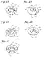
- Figures 3A-3C show perspective views of several embodiments of the first pivot plate according to the present invention.
- FIGS 4A-4B show perspective views of several embodiments of the second pivot plate according to the present invention.
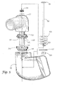
- Figure 5 shows an exploded perspective view of the detent joint according to the present invention
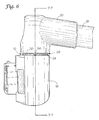
- Figure 6 shows a side elevation view of the detent joint according to the present invention
- Figure 7A shows a cross-section view of the detent joint in Figure 6 according to the present invention
- Figure 7B shows a cross-section view of the detent joint in Figure 7A in an angled orientation according to the present invention.
- Figures 8A-8B show cross-section views of alternative embodiments of the pivot plates according to the present invention.
- an external vehicle mirror assembly designated generally as 10, which includes a multi-axis pivoting detent joint, designated generally as 12, on both an upper mounting bracket 14 and lower mounting bracket 16.
- Mounting brackets 14 and 16 are generally identical and the following detailed description in regard to mounting bracket 16 applies equally to mounting bracket 14.
- the illustrated embodiment shows both an upper and lower mounting bracket 14 and 16, it is understood that various alternative mirror assembly designs that hang from a single upper mounting bracket or rest on a single lower mounting bracket are considered within the spirit and scope of the present invention. Incorporating both an upper and lower mounting bracket may not be required for practicing the present invention and is dependent upon the qualified design for a given vehicle.
- Mounting bracket 16 is adapted for attachment to a vehicle exterior.
- a support arm 18 is attached to mounting bracket 16.
- the connection of support arm 18 to mounting bracket 16 is accomplished by providing an arm connector 20, which interconnects mounting bracket 16 and support arm 18 in a multi-axis pivotal cooperation as described herein below.
- Support arm 18 is secured to arm connector 20 using any of various methods well-known to those skilled in the art, such as through bolting, screwing, gluing or friction fit.
- arm connector 20 and its elements, such as connector post 46 as detailed herein, can be a molded end of support arm 18 as opposed to a separate component.
- arm connector 20 is spring biased against mounting bracket 16 to provide resistance for detent joint 12 to hold mirror head 22 and support arm 18 in a desired position.
- detent joint 12 Disposed between mounting bracket 16 and arm connector 20 is detent joint 12 having rounded cooperating surface geometries to allow for multi-axis pivoting. This arrangement allows arm connector 20, and thus support arm 18, to pivot in a multi-axis arrangement on mounting bracket 16 to accommodate misalignment during installation on the vehicle.
- detent joint 12 includes a first pivot plate 24 carried by mounting bracket 16.
- First pivot plate 24 is fixed to mounting bracket 16 to resist rotation on mounting bracket 16 to provide a first half of detent joint 12.
- first pivot plate 24 includes an upper surface, designated generally as 25, having a concave shape.
- a series of grooves 26 are defined into upper surface 25.
- grooves 26 are curved to follow the same radius of curvature as upper surface 25.
- grooves 26 may be formed in a generally straight configuration.
- Grooves 26 essentially segment upper surface 25 into a series of ridges 28, which together with grooves 26 provide a first half of the detent function to detent joint 12.
- the concave shape of upper surface 25 is a spherical segment in that the radius of curvature is such that if extended would form a sphere. Accordingly, while the concave shape of upper surface 25 is only a spherical segment, it is spherical in radius of curvature to provide a rounded uniform engaging surface across first pivot plate 24. Alternatively, a non-spherical radius of curvatures may be used but is not the preferred embodiment as such a surface on first pivot plate 24 can result in uneven wear and possible premature joint failure due to the uneven application of forces.
- the other half of detent joint 12 includes a second pivot plate 30 carried by arm connector 20 that includes a convex rounded base surface 32 complementary to the concave shape of first pivot plate 24.
- Convex rounded base surface 32 is received into a recess 34 defined by concave upper surface 25 of first pivot plate 24.
- Second pivot plate 30 includes a plurality of rounded teeth 36 protruding from the convex shaped base surface 32 engaging in a complimentary fashion with grooves 26 of first pivot plate 24 so that base surface 32 is spaced from concave upper surface 25 to form a pivot gap 38 ( Fig. 6 ) there between.
- Pivot gap 38 allows rounded teeth 36 to both pivot and slide in grooves 26 of first pivot plate 24 so that arm connector 20 is pivotal in a multi-axis arrangement with mounting bracket 16 to accommodate misalignment between mounting bracket 16 and support arm 18 during installation on a vehicle.
- base surface 32 includes a radius of curvature complementary to the radius of curvature of concave upper surface 25, which is preferably spherical, so that pivot gap 38 is maintained between base surface 32 and concave upper surface 25 during pivotal movement of arm connector 20 on mounting bracket 16.
- Pivot gap 38 provided by rounded teeth 36 prevents base surface 32 from engagement with upper surface 25 of first pivot plate 24.
- pivot gap 38 allows second pivot plate 30 to pivot in any direction approximately +/- 5°.
- rounded teeth 36 are rounded to conform to grooves 26 in first pivot plate 24. This allows teeth 36 to easily slide laterally within grooves 26 to accommodate pivoting along a first axis. Further, rounded teeth 36 also allow second pivot plate 30 to easily pivot within a groove, for example in a fore and aft direction within the grooves, to accommodate pivoting along a second axis.
- the engagement of teeth 36 with grooves 26 creates the typical detent function between first pivot plate 24 and second pivot plate 30 when the mechanism is spring loaded to create a bias tension between mounting bracket 16 and arm connector 20.
- rounded teeth 36 may include a metal coating, designated generally as 40 in Fig. 3 , or metal impregnation to harden and enhance the engaging surface with first pivot plate 24.
- first pivot plate 24 is formed with a convex upper surface 25 into which grooves 26 are formed.
- Second pivot plate 30 is then formed with a concave base surface 32 that forms a recess 34 for receiving convex upper surface 25 of first pivot plate 24.
- the resulting cooperation between the pivot plates is thus generally the same as outline above and a multi-axis pivoting detent joint is provided that maintains the same pivot gap 38.
- a central opening 42 is provided in first pivot plate 24.
- Central opening 42 is aligned with an interior cavity 44 of mounting bracket 16 to provide a continuous passage through first pivot plate 24 into interior cavity 44.
- Arm connector 20 includes a connector post 46 extending outward from arm connector 20.
- Second pivot plate 30 includes a complementary central opening 48 receiving connector post 46, which then extends through central opening 42 of first pivot plate 24 and into interior cavity 44 of mounting bracket 16 in a pivoting arrangement so that connector post 46 moves within interior cavity 44.
- Connector post 46 includes a hollow interior channel, designated generally as 50, defining a continuous passage from arm connector 20 to interior cavity 44 of mounting bracket 16.
- a securing rod 52 is disposed in hollow interior channel 50 interconnecting arm connector 20 to mounting bracket 16.
- Securing rod 52 is spring biased to compress arm connector 20 and mounting bracket 16 together.
- a pair of bias springs 54 and 55 are disposed at opposite distal ends of securing rod 52.
- spring 54 is secured to arm connector 20 by bolt head 51.
- Washer 57 is bolted to second distal end 53 by nut 59 to secure spring 55 around connector post 46 in interior cavity 44 of mounting bracket 16.
- the spring bias on securing rod 52 directs arm connector 20 against mounting bracket 16 to force first and second pivot plates together to provide sufficient resistant for detent joint 12. Referring to Fig.
- the detent function is provided by the spherical geometry of first pivot plate 24 and teeth 36 of second pivot plate 30.
- one half of detent joint 12 is one of a concave or convex shaped plate which includes a series of grooves and ridges.
- the other half of the joint comprised the other of a convex or concave shaped plate with a plurality of teeth for engaging the grooves in a complimentary arrangement.
- the contact between the components creates the typical detent function when the mechanism is spring loaded.
- a pivot gap 38 between the two pivot plates 24 and 30 of detent joint 12 allows for misalignment forgiveness by pivoting arm connector 20 in a multi-axis arrangement on mounting bracket 16.
Landscapes
- Engineering & Computer Science (AREA)
- Multimedia (AREA)
- Mechanical Engineering (AREA)
- Rear-View Mirror Devices That Are Mounted On The Exterior Of The Vehicle (AREA)
Abstract
Description
- This application claims priority from US Provisional Application filed January 2, 2008 under Application Number
61/009,760 - 1) Field of the Invention
- The present invention relates to exterior vehicle mirror assemblies, and more particularly, to a detent joint for large commercial vehicle mirror assemblies that involves rounded cooperating surface geometries to allow for multi-axis movement to accommodate misalignment between a mounting bracket and support arm when mounted to the vehicle, while maintaining the proper detent function to hold the mirror assembly in a desired position.
- 2) Description of Related Art
- Exterior mirror assemblies are known to include a detent connection joint between a mounting bracket attached to the vehicle and a support arm carrying the mirror head so that the mirror can be selectively positioned and held in place. However, manufacturing variances for large exterior vehicle mirror assemblies typically result in some degree of misalignment between the two detent surfaces when mounted to the vehicle. In some cases the parts are flexible enough to accommodate slight misalignment. This, however, leads to line and point contact location that create premature wear and tear on the joint. This wear will eventually cause the detent joint to loosen over time from vibration. Eventually, the joint will no longer hold the mirror in position. In other cases, the mirror assembly system will not accommodate misalignment and results in poor or limited detent performance when mounted to the vehicle.
-
U.S. Patent No. 4,186,905 (Brudy ) shows a truck mirror that includes a detent member with grooves and a complementary engaging member that includes spaced projections. Axial compression of a spring moves the grooves into engagement with the projections. There is no disclosure in the specification of any tolerance for misalignment in this arrangement. Movement of this detent mechanism is limited strictly to a single vertical axis. -
U.S. Patent No. 5,081,546 (Bottrill ) shows a vehicle exterior mirror that includes detent formations that includes a compression spring. Misalignment is prevented by allowing a wobble in the washer connector as described in the specification at col. 3, lines 10-20. There is no disclosure of cooperating rounded surfaces on the detent mechanism to allow for multi-axis movement. -
U.S. Patent No. 7,137,715 (Schuurmans et al. ) shows an external vehicle mirror that includes cooperating engaging members to form a detent arrangement, and a spring adapted to hold the detent arrangement engaged. There is no disclosure of cooperating rounded surfaces on the detent mechanism to accommodate misalignment and allow for multi-axis movement. - None of the cited patents or known prior art teach a detent joint having a rounded, and preferably partial spherical segment, surface to allow for multi-axis rotation while maintaining proper detent resistance. Thus, there is a need for improvement in the art to provide a detent joint for exterior mirror assemblies that maintains a proper detent connection while preventing uneven wear and accommodating misalignment.
- Accordingly, it is an object of the present invention to provide a detent connection that will forgive misalignment between a mounting bracket and support arm.
- It is a further object of the present invention to provide a detent geometry in which the engaging components are rounded in a generally spherical segment shape to allow for multi-axis movement.
- The above objectives are accomplished according to the present invention by providing a spherical geometry to the detent joint between the two interacting joint parts. More particularly, the above objectives are accomplished according to the present invention by providing a mirror assembly comprising a mounting bracket for attachment to a vehicle exterior; a support arm carried by the mounting bracket for carrying a mirror head; an arm connector carried generally at a distal end of the support arm being pivotally connected to the mounting bracket; and a multi-axis pivoting detent joint interconnecting the mounting bracket and the arm connector. The detent joint includes a first pivot plate carried by the mounting bracket having a concave upper surface with a series of grooves formed therein; and, a second pivot plate carried by the arm connector having a rounded convex base surface received into a recess defined by the concave upper surface of the first pivot plate, and a plurality of rounded teeth protruding from the base surface engaging the grooves in the first pivot plate so that the base surface is spaced from the concave upper surface to form a pivot gap there between; whereby the pivot gap allows the rounded teeth to both pivot and slide in the grooves of the first pivot plate so that the arm connector is pivotal in a multi-axis arrangement with the mounting bracket to accommodate misalignment between the mounting bracket and the support arm during installation on a vehicle.
- In a further embodiment, the first pivot plate includes a central opening aligned with an interior cavity of the mounting bracket to provide a continuous passage through the first pivot plate into the interior cavity.
- In a further embodiment, the second pivot plate includes a complementary central opening aligned with the central opening of the first pivot plate.
- In a further embodiment, the arm connector includes a connector post extending through the central opening of the first pivot plate and the second pivot plate into the interior cavity of the mounting bracket in a pivoting arrangement so that the connector post moves within the interior cavity.
- In a further embodiment, the connector post includes a hollow interior channel defining a continuous passage from the arm connector to the interior cavity of the mounting bracket.
- In a further embodiment, a securing rod is disposed in the hollow interior channel of the arm connector interconnecting the arm connector to the mounting bracket. The securing rod is spring biased to direct the first pivot plate against the second pivot plate to maintain proper resistance of the detent joint to prevent unwanted movement of the support arm.
- In a further embodiment, the concave upper surface and the convex base surface each have a radius of curvature comprising a spherical segment.
- In a further embodiment, the base surface includes a radius of curvature complementary to the radius of curvature of the concave upper surface so that the pivot gap is maintained between the base surface and the concave upper surface during pivotal movement of the arm connector on the mounting bracket.
- In a further embodiment, the pivot gap allows for a pivotal movement of at least +/- 2° between the arm connector and the mounting bracket.
- In a further embodiment, the rounded teeth include a metal coating to harden and enhance the durability of the teeth.
- The construction designed to carry out the invention will hereinafter be described, together with other features thereof. The invention will be more readily understood from a reading of the following specification and by reference to the accompanying drawings forming a part thereof, wherein an example of the invention is shown and wherein:
-
Figure 1 shows a perspective view of a mirror assembly for mounting to a vehicle exterior having a multi-axis pivoting detent joint according to the present invention; -
Figure 2 shows a detailed perspective view of a detent joint according to the present invention; -
Figures 3A-3C show perspective views of several embodiments of the first pivot plate according to the present invention; -
Figures 4A-4B show perspective views of several embodiments of the second pivot plate according to the present invention; -
Figure 5 shows an exploded perspective view of the detent joint according to the present invention; -
Figure 6 shows a side elevation view of the detent joint according to the present invention; -
Figure 7A shows a cross-section view of the detent joint inFigure 6 according to the present invention; -
Figure 7B shows a cross-section view of the detent joint inFigure 7A in an angled orientation according to the present invention; and, -
Figures 8A-8B show cross-section views of alternative embodiments of the pivot plates according to the present invention. - With reference to the drawings, the invention will now be described in more detail. Referring to
Figs. 1 and2 , an external vehicle mirror assembly, designated generally as 10, is shown which includes a multi-axis pivoting detent joint, designated generally as 12, on both anupper mounting bracket 14 andlower mounting bracket 16.Mounting brackets bracket 16 applies equally to mountingbracket 14. Further, while the illustrated embodiment shows both an upper andlower mounting bracket -
Mounting bracket 16 is adapted for attachment to a vehicle exterior. Asupport arm 18 is attached to mountingbracket 16. In the illustrated embodiment, the connection ofsupport arm 18 to mountingbracket 16 is accomplished by providing anarm connector 20, which interconnects mountingbracket 16 and supportarm 18 in a multi-axis pivotal cooperation as described herein below.Support arm 18 is secured toarm connector 20 using any of various methods well-known to those skilled in the art, such as through bolting, screwing, gluing or friction fit. Alternatively,arm connector 20 and its elements, such as connector post 46 as detailed herein, can be a molded end ofsupport arm 18 as opposed to a separate component. Preferably,arm connector 20 is spring biased against mountingbracket 16 to provide resistance for detent joint 12 to holdmirror head 22 andsupport arm 18 in a desired position. Disposed between mountingbracket 16 andarm connector 20 is detent joint 12 having rounded cooperating surface geometries to allow for multi-axis pivoting. This arrangement allowsarm connector 20, and thus supportarm 18, to pivot in a multi-axis arrangement on mountingbracket 16 to accommodate misalignment during installation on the vehicle. - Referring to
Figs. 2 ,5 and6 , detent joint 12 includes afirst pivot plate 24 carried by mountingbracket 16.First pivot plate 24 is fixed to mountingbracket 16 to resist rotation on mountingbracket 16 to provide a first half of detent joint 12. Further referring toFigs 3A and 3C ,first pivot plate 24 includes an upper surface, designated generally as 25, having a concave shape. A series ofgrooves 26 are defined intoupper surface 25. Referring toFig. 3C , in apreferred embodiment grooves 26 are curved to follow the same radius of curvature asupper surface 25. Alternatively, however, as shown inFig. 3A ,grooves 26 may be formed in a generally straight configuration.Grooves 26 essentially segmentupper surface 25 into a series ofridges 28, which together withgrooves 26 provide a first half of the detent function to detent joint 12. In a preferred embodiment, the concave shape ofupper surface 25 is a spherical segment in that the radius of curvature is such that if extended would form a sphere. Accordingly, while the concave shape ofupper surface 25 is only a spherical segment, it is spherical in radius of curvature to provide a rounded uniform engaging surface acrossfirst pivot plate 24. Alternatively, a non-spherical radius of curvatures may be used but is not the preferred embodiment as such a surface onfirst pivot plate 24 can result in uneven wear and possible premature joint failure due to the uneven application of forces. - Further referring to
Fig. 4A and8A , the other half of detent joint 12 includes asecond pivot plate 30 carried byarm connector 20 that includes a convexrounded base surface 32 complementary to the concave shape offirst pivot plate 24. Convex roundedbase surface 32 is received into arecess 34 defined by concaveupper surface 25 offirst pivot plate 24.Second pivot plate 30 includes a plurality ofrounded teeth 36 protruding from the convex shapedbase surface 32 engaging in a complimentary fashion withgrooves 26 offirst pivot plate 24 so thatbase surface 32 is spaced from concaveupper surface 25 to form a pivot gap 38 (Fig. 6 ) there between.Pivot gap 38 allows roundedteeth 36 to both pivot and slide ingrooves 26 offirst pivot plate 24 so thatarm connector 20 is pivotal in a multi-axis arrangement with mountingbracket 16 to accommodate misalignment between mountingbracket 16 andsupport arm 18 during installation on a vehicle. In a preferred embodiment,base surface 32 includes a radius of curvature complementary to the radius of curvature of concaveupper surface 25, which is preferably spherical, so thatpivot gap 38 is maintained betweenbase surface 32 and concaveupper surface 25 during pivotal movement ofarm connector 20 on mountingbracket 16.Pivot gap 38 provided byrounded teeth 36 preventsbase surface 32 from engagement withupper surface 25 offirst pivot plate 24. Preferably,pivot gap 38 allowssecond pivot plate 30 to pivot in any direction approximately +/- 5°. - Preferably,
rounded teeth 36 are rounded to conform togrooves 26 infirst pivot plate 24. This allowsteeth 36 to easily slide laterally withingrooves 26 to accommodate pivoting along a first axis. Further,rounded teeth 36 also allowsecond pivot plate 30 to easily pivot within a groove, for example in a fore and aft direction within the grooves, to accommodate pivoting along a second axis. The engagement ofteeth 36 withgrooves 26 creates the typical detent function betweenfirst pivot plate 24 andsecond pivot plate 30 when the mechanism is spring loaded to create a bias tension between mountingbracket 16 andarm connector 20. To increase durability, roundedteeth 36 may include a metal coating, designated generally as 40 inFig. 3 , or metal impregnation to harden and enhance the engaging surface withfirst pivot plate 24. - Referring to
Figs. 3B, 4B , and8B , an alternative arrangement is illustrated for detent joint 12 in which the surface geometries offirst pivot plate 24 andsecond pivot plate 30 are reversed. In this embodiment,first pivot plate 24 is formed with a convexupper surface 25 into whichgrooves 26 are formed.Second pivot plate 30 is then formed with aconcave base surface 32 that forms arecess 34 for receiving convexupper surface 25 offirst pivot plate 24. The resulting cooperation between the pivot plates is thus generally the same as outline above and a multi-axis pivoting detent joint is provided that maintains thesame pivot gap 38. - Referring further to
Figures 5 ,7A and7B , in the illustrated embodiment acentral opening 42 is provided infirst pivot plate 24.Central opening 42 is aligned with aninterior cavity 44 of mountingbracket 16 to provide a continuous passage throughfirst pivot plate 24 intointerior cavity 44.Arm connector 20 includes aconnector post 46 extending outward fromarm connector 20.Second pivot plate 30 includes a complementarycentral opening 48 receivingconnector post 46, which then extends throughcentral opening 42 offirst pivot plate 24 and intointerior cavity 44 of mountingbracket 16 in a pivoting arrangement so thatconnector post 46 moves withininterior cavity 44.Connector post 46 includes a hollow interior channel, designated generally as 50, defining a continuous passage fromarm connector 20 tointerior cavity 44 of mountingbracket 16. A securingrod 52 is disposed in hollowinterior channel 50interconnecting arm connector 20 to mountingbracket 16. Securingrod 52 is spring biased to compressarm connector 20 and mountingbracket 16 together. Preferably, a pair of bias springs 54 and 55 are disposed at opposite distal ends of securingrod 52. In the illustrated embodiment,spring 54 is secured toarm connector 20 bybolt head 51.Washer 57 is bolted to seconddistal end 53 bynut 59 to securespring 55 aroundconnector post 46 ininterior cavity 44 of mountingbracket 16. The spring bias on securingrod 52 directsarm connector 20 against mountingbracket 16 to force first and second pivot plates together to provide sufficient resistant for detent joint 12. Referring toFig. 7B , whenarm connector 20 is moved to a maximum allowable pivot range, connector post 46 contacts aside wall 56 ofinterior cavity 44 in mountingbracket 16 to prevent further movement. By adjusting the gap betweenside walls interior cavity 44, the extent to whicharm connector 20 pivots can be controlled. Most preferably, the pivot range betweenarm connector 20 and mountingbracket 16 is limited to +/- 2° to avoid unintended play in the mirror assembly. - In summary, the detent function is provided by the spherical geometry of
first pivot plate 24 andteeth 36 ofsecond pivot plate 30. In the illustrated embodiment, one half of detent joint 12 is one of a concave or convex shaped plate which includes a series of grooves and ridges. The other half of the joint comprised the other of a convex or concave shaped plate with a plurality of teeth for engaging the grooves in a complimentary arrangement. The contact between the components creates the typical detent function when the mechanism is spring loaded. However, apivot gap 38 between the twopivot plates arm connector 20 in a multi-axis arrangement on mountingbracket 16. - While a preferred embodiment of the invention has been described using specific terms, such description is for illustrative purposes only, and it is to be understood that changes and variations may be made without departing from the spirit or scope of the following claims.
Claims (20)
- An exterior vehicle mirror assembly having a pivoting detent joint, said mirror assembly comprising:a mounting bracket for attachment to a vehicle exterior;a support arm carried by said mounting bracket for carrying a mirror head;an arm connector carried generally at a distal end of said support arm being pivotally connected to said mounting bracket;a multi-axis pivoting detent joint interconnecting said mounting bracket and said arm connector, said detent joint including:whereby said pivot gap allows said rounded teeth to both pivot and slide in said grooves of said first pivot plate so that said arm connector is pivotal in a multi-axis arrangement with said mounting bracket to accommodate misalignment between said mounting bracket and said support arm during installation on a vehicle.a first pivot plate carried by said mounting bracket having a concave upper surface with a series of grooves formed therein; and,a second pivot plate carried by said arm connector having a rounded convex base surface received into a recess defined by said concave upper surface of said first pivot plate, and a plurality of rounded teeth protruding from said base surface engaging said grooves in said first pivot plate so that said base surface is spaced from said concave upper surface to form a pivot gap there between;
- The assembly of claim 1 wherein said first pivot plate includes a central opening aligned with an interior cavity of said mounting bracket to provide a continuous passage through said first pivot plate into said interior cavity.
- The assembly of claim 2 wherein said second pivot plate includes a complementary central opening aligned with said central opening of said first pivot plate.
- The assembly of claim 3 wherein said arm connector includes a connector post extending through said central opening of said first pivot plate and said second pivot plate into said interior cavity of said mounting bracket in a pivoting arrangement so that said connector post moves within said interior cavity.
- The assembly of claim 4 wherein said connector post includes a hollow interior channel defining a continuous passage from said arm connector to said interior cavity of said mounting bracket.
- The assembly of claim 5 including a securing rod disposed in said hollow interior channel of said arm connector interconnecting said arm connector to said mounting bracket.
- The assembly of claim 6 wherein said securing rod is spring biased to direct said first pivot plate against said second pivot plate to maintain proper resistance of said detent joint to prevent unwanted movement of said support arm.
- The assembly of claim 1 wherein said concave upper surface and said convex base surface each have a radius of curvature comprising a spherical segment.
- The assembly of claim 1 wherein said base surface includes a radius of curvature complementary to said radius of curvature of said concave upper surface so that said pivot gap is maintained between said base surface and said concave upper surface during pivotal movement of said arm connector on said mounting bracket.
- The assembly of claim 1 wherein said pivot gap allows for a pivotal movement of at least +/- 2° between said arm connector and said mounting bracket.
- The assembly of claim 1 wherein said rounded teeth include a metal coating to harden and enhance the durability of said teeth.
- A multi-axis pivoting detent joint assembly for an exterior vehicle mirror comprising:a mounting bracket for attachment to a vehicle exterior;a first pivot plate included in said mounting bracket having a concave upper surface with a series of grooves formed therein;a support arm pivotally carried on said first pivot plate of said mounting bracket; and,a second pivot plate carried by said support arm having a base surface with a plurality of protruding teeth engaging said grooves in said first pivot plate so that a pivot gap is defined between said upper surface of said first pivot plate and said base surface of second pivot plate;whereby said pivot gap allows said teeth to both pivot and slide in said grooves of said first pivot plate so that said support arm is pivotal in a multi-axis arrangement with said mounting bracket to accommodate misalignment between said mounting bracket and said support arm during installation on a vehicle.
- The assembly of claim 12 wherein said grooves are curved to follow the same radius of curvature as said concave upper surface.
- The assembly of claim 12 wherein said base surface has a convex shape and is received into a recess defined by said concave upper surface of said first pivot plate.
- The assembly of claim 12 wherein said first pivot plate includes a central opening aligned with an interior cavity of said mounting bracket to provide a continuous passage through said first pivot plate into said interior cavity.
- The assembly of claim 15 wherein said support arm includes a connector post extending through said central opening of said first pivot plate and into said interior cavity of said mounting bracket in a pivoting arrangement so that said connector post moves within said interior cavity.
- The assembly of claim 16 wherein said connector post includes a hollow interior channel defining a continuous passage generally from said support arm to said interior cavity of said mounting bracket.
- The assembly of claim 17 including a securing rod disposed in said hollow interior channel being spring biased to direct said first pivot plate against said second pivot plate to maintain proper resistance of said detent joint to prevent unwanted movement of said support arm.
- A multi-axis pivoting detent joint assembly for an exterior vehicle mirror comprising:a mounting bracket for attachment to a vehicle exterior;a first pivot plate carried by said mounting bracket having a convex upper surface with a series of grooves formed therein;a support arm pivotally carried on said first pivot plate of said mounting bracket; and,a second pivot plate carried by said support arm having a concave base surface with a plurality of protruding teeth engaging said grooves in said first pivot plate so that a pivot gap is defined between said upper surface of said first pivot plate and said base surface of second pivot plate;whereby said pivot gap allows said teeth to both pivot and slide in said grooves of said first pivot plate so that said support arm is pivotal in a multi-axis arrangement with said mounting bracket to accommodate misalignment between said mounting bracket and said support arm during installation on a vehicle.
- The assembly of claim 19 wherein said concave base surface includes a radius of curvature complementary to said radius of curvature of said convex upper surface so that said pivot gap is maintained between said base surface and said concave upper surface during pivotal movement of said support arm on said mounting bracket.
Applications Claiming Priority (2)
| Application Number | Priority Date | Filing Date | Title |
|---|---|---|---|
| US976008P | 2008-01-02 | 2008-01-02 | |
| US12/317,365 US7878477B2 (en) | 2008-01-02 | 2008-12-22 | Multi-axis pivoting detent joint assembly for an exterior vehicle mirror |
Publications (2)
| Publication Number | Publication Date |
|---|---|
| EP2077205A2 true EP2077205A2 (en) | 2009-07-08 |
| EP2077205A3 EP2077205A3 (en) | 2009-11-04 |
Family
ID=40551291
Family Applications (1)
| Application Number | Title | Priority Date | Filing Date |
|---|---|---|---|
| EP08173112A Withdrawn EP2077205A3 (en) | 2008-01-02 | 2008-12-30 | A multi-axis pivoting detent joint assembly for an exterior vehicle mirror |
Country Status (1)
| Country | Link |
|---|---|
| EP (1) | EP2077205A3 (en) |
Cited By (4)
| Publication number | Priority date | Publication date | Assignee | Title |
|---|---|---|---|---|
| GB2474435A (en) * | 2009-10-13 | 2011-04-20 | Ashtree Glass Ltd | A mirror assembly having various indexed positions suitable for a vehicle |
| CN102476604A (en) * | 2010-11-25 | 2012-05-30 | 苏州卫生职业技术学院 | Lateral side road condition observation mirror for automobile |
| CN109969085A (en) * | 2017-12-07 | 2019-07-05 | 玛泽胜创新有限公司 | Rear view device, method of assembling the same, and motor vehicle with rear view device |
| EP3756951A1 (en) | 2019-06-28 | 2020-12-30 | CNH Industrial Belgium N.V. | Remote retractable mirror |
Citations (3)
| Publication number | Priority date | Publication date | Assignee | Title |
|---|---|---|---|---|
| US4186905A (en) | 1975-06-09 | 1980-02-05 | Dominion Auto Accessories Limited | Retractable truck mirror |
| US5081546A (en) | 1989-07-22 | 1992-01-14 | Britax Wingard Limited | Vehicle exterior mirror |
| US7137715B2 (en) | 2001-03-26 | 2006-11-21 | Schefenacker Vision Systems Australia Pty Ltd. | External vehicle mirror having a self-loading pivot and an end stop |
Family Cites Families (2)
| Publication number | Priority date | Publication date | Assignee | Title |
|---|---|---|---|---|
| JPH04136949U (en) * | 1991-06-17 | 1992-12-21 | 株式会社村上開明堂 | foldable door mirror |
| WO2005068257A1 (en) * | 2004-01-13 | 2005-07-28 | Truck-Lite Co., Inc. | Clutch assembly for breakaway mirror |
-
2008
- 2008-12-30 EP EP08173112A patent/EP2077205A3/en not_active Withdrawn
Patent Citations (3)
| Publication number | Priority date | Publication date | Assignee | Title |
|---|---|---|---|---|
| US4186905A (en) | 1975-06-09 | 1980-02-05 | Dominion Auto Accessories Limited | Retractable truck mirror |
| US5081546A (en) | 1989-07-22 | 1992-01-14 | Britax Wingard Limited | Vehicle exterior mirror |
| US7137715B2 (en) | 2001-03-26 | 2006-11-21 | Schefenacker Vision Systems Australia Pty Ltd. | External vehicle mirror having a self-loading pivot and an end stop |
Cited By (7)
| Publication number | Priority date | Publication date | Assignee | Title |
|---|---|---|---|---|
| GB2474435A (en) * | 2009-10-13 | 2011-04-20 | Ashtree Glass Ltd | A mirror assembly having various indexed positions suitable for a vehicle |
| GB2474435B (en) * | 2009-10-13 | 2015-11-25 | Ashtree Vision & Safety Ltd | A mirror arm assembly |
| CN102476604A (en) * | 2010-11-25 | 2012-05-30 | 苏州卫生职业技术学院 | Lateral side road condition observation mirror for automobile |
| CN109969085A (en) * | 2017-12-07 | 2019-07-05 | 玛泽胜创新有限公司 | Rear view device, method of assembling the same, and motor vehicle with rear view device |
| EP3756951A1 (en) | 2019-06-28 | 2020-12-30 | CNH Industrial Belgium N.V. | Remote retractable mirror |
| WO2020260521A1 (en) | 2019-06-28 | 2020-12-30 | Cnh Industrial Belgium Nv | Remote retractable mirror |
| US11789231B2 (en) | 2019-06-28 | 2023-10-17 | Cnh Industrial America Llc | Remote retractable mirror |
Also Published As
| Publication number | Publication date |
|---|---|
| EP2077205A3 (en) | 2009-11-04 |
Similar Documents
| Publication | Publication Date | Title |
|---|---|---|
| US7878477B2 (en) | Multi-axis pivoting detent joint assembly for an exterior vehicle mirror | |
| EP2110283A1 (en) | Pivoting Detent Joint | |
| US8246266B2 (en) | Linkage arrangement for the adjustment of rearview mirrors | |
| US9987972B2 (en) | High extraction force ball socket | |
| US9464663B2 (en) | Ball joint | |
| EP2077205A2 (en) | A multi-axis pivoting detent joint assembly for an exterior vehicle mirror | |
| EP1731368A1 (en) | Conical joint for a vehicle mirror | |
| JP2002534311A (en) | Automotive wiper with means for connecting wiper blades | |
| JP7088844B2 (en) | Door holder | |
| US7658360B2 (en) | Seat sliding apparatus for vehicle | |
| CN108778835A (en) | System and method for auxiliary clamp component to be fixed on to vehicle part | |
| EP0285262B1 (en) | Wiperblade of windshield wiper | |
| CN107640068B (en) | Hinge locking mechanism for seat back | |
| US20060059960A1 (en) | Flexible mounting assembly for a laundry appliance and method of use | |
| PL201458B1 (en) | Wiper arm | |
| US20100328795A1 (en) | Mirror Damper | |
| US3711134A (en) | One-piece clevis | |
| US6105944A (en) | Mount and bonded component therefor with shape factor reducing notches | |
| US10240712B2 (en) | Ball mount assembly for vehicle | |
| US20050104413A1 (en) | High rotation angle for gas spring connection | |
| CN112914407B (en) | Hinge for mounting a toilet support | |
| US3933058A (en) | Universal support for vehicle mirror | |
| KR101503758B1 (en) | Retention hinge component, in particular for maintaining an external rearview mirror of a utility vehicle and external rearview mirror for a utility vehicle comprising said type of retention hinge component | |
| JP3695161B2 (en) | Automotive headrest structure | |
| CN210715530U (en) | Cable assembly and vehicle with same |
Legal Events
| Date | Code | Title | Description |
|---|---|---|---|
| PUAI | Public reference made under article 153(3) epc to a published international application that has entered the european phase |
Free format text: ORIGINAL CODE: 0009012 |
|
| AK | Designated contracting states |
Kind code of ref document: A2 Designated state(s): AT BE BG CH CY CZ DE DK EE ES FI FR GB GR HR HU IE IS IT LI LT LU LV MC MT NL NO PL PT RO SE SI SK TR |
|
| AX | Request for extension of the european patent |
Extension state: AL BA MK RS |
|
| PUAL | Search report despatched |
Free format text: ORIGINAL CODE: 0009013 |
|
| AK | Designated contracting states |
Kind code of ref document: A3 Designated state(s): AT BE BG CH CY CZ DE DK EE ES FI FR GB GR HR HU IE IS IT LI LT LU LV MC MT NL NO PL PT RO SE SI SK TR |
|
| AX | Request for extension of the european patent |
Extension state: AL BA MK RS |
|
| RAP1 | Party data changed (applicant data changed or rights of an application transferred) |
Owner name: MEKRA LANG GMBH & CO. KG |
|
| AKX | Designation fees paid | ||
| STAA | Information on the status of an ep patent application or granted ep patent |
Free format text: STATUS: THE APPLICATION IS DEEMED TO BE WITHDRAWN |
|
| 18D | Application deemed to be withdrawn |
Effective date: 20100505 |
|
| REG | Reference to a national code |
Ref country code: DE Ref legal event code: 8566 |