EP2075937A2 - Frame-interleaving systems and methods for 100G optical transport enabling multi-level optical transmission - Google Patents
Frame-interleaving systems and methods for 100G optical transport enabling multi-level optical transmission Download PDFInfo
- Publication number
- EP2075937A2 EP2075937A2 EP08253358A EP08253358A EP2075937A2 EP 2075937 A2 EP2075937 A2 EP 2075937A2 EP 08253358 A EP08253358 A EP 08253358A EP 08253358 A EP08253358 A EP 08253358A EP 2075937 A2 EP2075937 A2 EP 2075937A2
- Authority
- EP
- European Patent Office
- Prior art keywords
- client signal
- paths
- transport
- frame
- optical
- Prior art date
- Legal status (The legal status is an assumption and is not a legal conclusion. Google has not performed a legal analysis and makes no representation as to the accuracy of the status listed.)
- Withdrawn
Links
- 230000003287 optical effect Effects 0.000 title claims abstract description 95
- 238000000034 method Methods 0.000 title claims abstract description 82
- 230000005540 biological transmission Effects 0.000 title abstract description 20
- 238000009432 framing Methods 0.000 claims abstract description 20
- 238000012937 correction Methods 0.000 claims abstract description 14
- 239000000872 buffer Substances 0.000 claims description 28
- 238000012423 maintenance Methods 0.000 claims description 15
- 238000012544 monitoring process Methods 0.000 claims description 13
- 238000013507 mapping Methods 0.000 claims description 11
- 230000002776 aggregation Effects 0.000 claims description 4
- 238000004220 aggregation Methods 0.000 claims description 4
- 238000010586 diagram Methods 0.000 description 30
- 238000004891 communication Methods 0.000 description 12
- 238000000638 solvent extraction Methods 0.000 description 4
- 239000000470 constituent Substances 0.000 description 3
- 238000011161 development Methods 0.000 description 3
- 230000018109 developmental process Effects 0.000 description 3
- 238000005516 engineering process Methods 0.000 description 3
- 230000010363 phase shift Effects 0.000 description 3
- 238000013459 approach Methods 0.000 description 2
- 230000003595 spectral effect Effects 0.000 description 2
- 230000001360 synchronised effect Effects 0.000 description 2
- 238000009825 accumulation Methods 0.000 description 1
- 230000007547 defect Effects 0.000 description 1
- 239000006185 dispersion Substances 0.000 description 1
- 238000002474 experimental method Methods 0.000 description 1
- 230000006855 networking Effects 0.000 description 1
- 239000013307 optical fiber Substances 0.000 description 1
- 238000012545 processing Methods 0.000 description 1
- 230000008929 regeneration Effects 0.000 description 1
- 238000011069 regeneration method Methods 0.000 description 1
Images



Classifications
-
- H—ELECTRICITY
- H04—ELECTRIC COMMUNICATION TECHNIQUE
- H04J—MULTIPLEX COMMUNICATION
- H04J3/00—Time-division multiplex systems
- H04J3/02—Details
- H04J3/04—Distributors combined with modulators or demodulators
- H04J3/047—Distributors with transistors or integrated circuits
-
- H—ELECTRICITY
- H04—ELECTRIC COMMUNICATION TECHNIQUE
- H04J—MULTIPLEX COMMUNICATION
- H04J3/00—Time-division multiplex systems
- H04J3/16—Time-division multiplex systems in which the time allocation to individual channels within a transmission cycle is variable, e.g. to accommodate varying complexity of signals, to vary number of channels transmitted
- H04J3/1605—Fixed allocated frame structures
- H04J3/1652—Optical Transport Network [OTN]
-
- H—ELECTRICITY
- H04—ELECTRIC COMMUNICATION TECHNIQUE
- H04J—MULTIPLEX COMMUNICATION
- H04J3/00—Time-division multiplex systems
- H04J3/16—Time-division multiplex systems in which the time allocation to individual channels within a transmission cycle is variable, e.g. to accommodate varying complexity of signals, to vary number of channels transmitted
- H04J3/1605—Fixed allocated frame structures
- H04J3/1652—Optical Transport Network [OTN]
- H04J3/1658—Optical Transport Network [OTN] carrying packets or ATM cells
-
- H—ELECTRICITY
- H04—ELECTRIC COMMUNICATION TECHNIQUE
- H04L—TRANSMISSION OF DIGITAL INFORMATION, e.g. TELEGRAPHIC COMMUNICATION
- H04L1/00—Arrangements for detecting or preventing errors in the information received
- H04L1/004—Arrangements for detecting or preventing errors in the information received by using forward error control
- H04L1/0056—Systems characterized by the type of code used
- H04L1/0071—Use of interleaving
Definitions
- the present invention relates generally to the optical networking field. More specifically, the preferred embodiment relates to frame-interleaving systems and methods for Optical Transport Unit K (OTUK) (i.e. Optical Transport Unit 4 (OTU4)), 100Gb/s Ethernet (100GbE), and other 100Gb/s (100G) optical transport enabling multi-level optical transmission.
- OTUK Optical Transport Unit K
- OTU4 Optical Transport Unit 4
- 100Gb/s Ethernet 100Gb/s Ethernet
- 100Gb/s (100G) optical transport enabling multi-level optical transmission.
- the frame-interleaving systems and methods of the present invention support the multiplexing of sub-rate clients, such as 10x10Gb/s (10G) clients, 2x40Gb/s (40G) plus 2x10G clients, etc., into two 50Gb/s (50G) transport signals, four 25Gb/s (25G) transport signals, etc.
- a 100G client signal or 100G aggregate client signal carried over two or more channels is frame-deinterleaved, followed by even/odd sub-channel FEC encoding and framing.
- a 100G client signal or 100G aggregate client signal carried over two or more channels is received and processed by a single 100G FEC framer, followed by frame-deinterleaving into two or more sub-rate channels.
- transmission and modulation format development falls into two categories: 1) 100G serial optical transmission as demonstrated by network gear providers and other researchers performing 100G optical transmission "hero" experiments, which focus on the accumulation of knowledge but not necessarily efficiency or cost-effectiveness, and 2) realistic transmission and modulation schemes that are based on present and future optical and electronic technologies, which typically involve transmission and modulation schemes that attempt to provide greater spectral efficiency, solve dispersion problems, and limit baud rates by providing multiple bits-per-symbol encodings and/or by using enhanced forward error correction (FEC) schemes, such as duo-binary modulation, Differential Phase Shift Keying (DPSK), Differential Quadrature Phase Shift Keying (DQPSK), and the like.
- FEC forward error correction
- OFDM Optical Transport Unit 4
- ITU-T International Telecommunications Union
- the present invention relates to a transport method as claimed in claims 1, 9 and 19 and a transport system as claimed in claim 17 and 18.
- the preferred embodiment provides frame-interleaving systems and methods for Optical Transport Unit K (OTUK) (i.e. Optical Transport Unit 4 (OTU4)), 100Gb/s Ethernet (100GbE), and other 100Gb/s (100G) optical transport enabling multi-level optical transmission.
- OTUK Optical Transport Unit K
- OTU4 Optical Transport Unit 4
- 100Gb/s Ethernet 100GbE
- 100Gb/s 100Gb/s
- 100Gb/s 100Gb/s
- 100Gb/s 100Gb/s Ethernet
- 100Gb/s 100Gb/s
- the frame-interleaving systems and methods of the present invention support the multiplexing of sub-rate clients, such as 10x10Gb/s (10G) clients, 2x40Gb/s (40G) plus 2x10G clients, etc., into two 50Gb/s (50G) transport signals, four 25Gb/s (25G) transport signals, etc.
- a 100G client signal or 100G aggregate client signal carried over two or more channels is frame-deinterleaved, followed by even/odd sub-channel FEC encoding and framing.
- a 100G client signal or 100G aggregate client signal carried over two or more channels is received and processed by a single 100G FEC framer, followed by frame-deinterleaving into two or more sub-rate channels.
- the frame-interleaving systems and methods of the present invention can be implemented in digital circuitry (i.e. a field-programmable gate array (FPGA) or the like) available today.
- FPGA field-programmable gate array
- the present invention provides a transport method, including: receiving an aggregate client signal; and deinterleaving the aggregate client signal across N paths, each of the N paths carrying one of every N frames into which the aggregate client signal is deinterleaved.
- Each of the N paths include a set of Optical Transport Network (OTN) overhead for individual path operations, administration, maintenance, and provisioning (OAM&P).
- Each of the N paths also include a set of Optical Transport Network (OTN) overhead for coordinated path operations, administration, maintenance, and provisioning (OAM&P).
- the transport method also includes performing forward error correction (FEC) decoding for each of the N paths one of prior to and subsequent to deinterleaving, performing overhead monitoring/termination/generation for each of the N paths one of prior to and subsequent to deinterleaving, performing forward error correction (FEC) encoding for each of the N paths one of prior to and subsequent to deinterleaving, performing Optical Data Unit K (ODUK) mapping for each of the N paths subsequent to deinterleaving, performing Generic Framing Protocol (GFP) mapping for each of the N paths subsequent to deinterleaving, and/or inserting one or more frame buffers into selected paths of the N paths subsequent to deinterleaving.
- FEC forward error correction
- ODUK Optical Data Unit K
- the aggregate client signal consists of an aggregate client signal selected from the group consisting of an Optical Transport Unit 4 (OTU4) client signal, an Optical Transport Unit K (OTUK) client signal, a constant bit rate (CBR) client signal, a 100Gb/s (100G) client signal, a 100Gb/s Ethernet (100GbE) Local Area Network (LAN) client signal, a 100Gb/s Ethernet (100GbE) Wide Area Network (WAN) client signal, a 100Gb/s Ethernet (100GbE) Generic Framing Protocol (GFP)-mapped client signal, a 10Gb/s Ethernet (10GbE) client signal, an Optical Channel 192 (OC192) client signal, an Optical Transport Unit 2 (OTU2) client signal, an Optical Transport Unit 2E (OTU2E) client signal, an Optical Data Unit 2 (ODU2) client signal, an Optical Data Unit 2 (ODU2) Local Area Network (LAN) (ODU2L) client signal, a subset thereof,
- the present invention provides a transport method, including: receiving N transport signals distributed across N paths; and interleaving the N transport signals to form an aggregate client signal, each of the N paths carrying one of every N frames from which the aggregate client signal is interleaved.
- Each of the N paths includes a set of Optical Transport Network (OTN) overhead for individual path operations, administration, maintenance, and provisioning (OAM&P).
- Each of the N paths also include a set of Optical Transport Network (OTN) overhead for coordinated path operations, administration, maintenance, and provisioning (OAM&P).
- the transport method also includes performing forward error correction (FEC) decoding for each of the N paths prior to interleaving, performing overhead monitoring/termination/generation for each of the N paths one of prior to and subsequent to interleaving, performing forward error correction (FEC) encoding for each of the N paths one of prior to and subsequent to interleaving, performing Optical Data Unit K (ODUK) demapping for each of the N paths prior to interleaving, performing Generic Framing Protocol (GFP) demapping for each of the N paths prior to interleaving, and/or inserting one or more frame buffers into selected paths of the N paths prior to interleaving.
- FEC forward error correction
- ODUK Optical Data Unit K
- GFP Generic Framing Protocol
- the aggregate client signal consists of an aggregate client signal selected from the group consisting of an Optical Transport Unit 4 (OTU4) client signal, an Optical Transport Unit K (OTUK) client signal, a constant bit rate (CBR) client signal, a 100Gb/s (100G) client signal, a 100Gb/s Ethernet (100GbE) Local Area Network (LAN) client signal, a 100Gb/s Ethernet (100GbE) Wide Area Network (WAN) client signal, a 100Gb/s Ethernet (100GbE) Generic Framing Protocol (GFP)-mapped client signal, a 10Gb/s Ethernet (10GbE) client signal, an Optical Channel 192 (OC192) client signal, an Optical Transport Unit 2 (OTU2) client signal, an Optical Transport Unit 2E (OTU2E) client signal, an Optical Data Unit 2 (ODU2) client signal, an Optical Data Unit 2 (ODU2) Local Area Network (LAN) (ODU2L) client signal, a subset thereof,
- the present invention provides transport system, including: one or more inputs for receiving an aggregate client signal; and a deinterleaver for deinterleaving the aggregate client signal across N paths, each of the N paths carrying one of every N frames into which the aggregate client signal is deinterleaved.
- the present provides a transport system, including: one or more inputs for receiving N transport signals distributed across N paths; and an interleaver for interleaving the N transport signals to form an aggregate client signal, each of the N paths carrying one of every N frames from which the aggregate client signal is interleaved.
- the present provides a transport method, including: transporting one of every N frames associated with an aggregate client signal over a selected one of N channels; wherein each of the N channels include a set of Optical Transport Network (OTN) overhead for individual path operations, administration, maintenance, and provisioning (OAM&P); and wherein each of the N channels include a set of Optical Transport Network (OTN) overhead for coordinated path operations, administration, maintenance, and provisioning (OAM&P).
- OTN Optical Transport Network
- OAM&P Optical Transport Network
- the present invention provides frame-interleaving systems and methods for Optical Transport Unit K (OTUK) (i.e. Optical Transport Unit 4 (OTU4)), 100Gb/s Ethernet (100GbE), and other 100Gb/s (100G) optical transport enabling multi-level optical transmission.
- OTUK Optical Transport Unit K
- OTU4 Optical Transport Unit 4
- 100Gb/s Ethernet 100GbE
- 100Gb/s 100Gb/s
- 100Gb/s 100Gb/s
- 100Gb/s 100Gb/s Ethernet
- 100Gb/s 100Gb/s
- the frame-interleaving systems and methods of the present invention support the multiplexing of sub-rate clients, such as 10x10Gb/s (10G) clients, 2x40Gb/s (40G) plus 2x10G clients, etc., into two 50Gb/s (50G) transport signals, four 25Gb/s (25G) transport signals, etc.
- a 100G client signal or 100G aggregate client signal carried over two or more channels is frame-deinterleaved, followed by even/odd sub-channel FEC encoding and framing.
- a 100G client signal or 100G aggregate client signal carried over two or more channels is received and processed by a single 100G FEC framer, followed by frame-deinterleaving into two or more sub-rate channels.
- the frame-interleaving systems and methods of the present invention can be implemented in digital circuitry (i.e.
- the frame-interleaving approach of the present invention is particularly applicable to the sub-rate multiplexing of multiple sub-rate client signals into a 100G transport signals, or a 2x50G or 4x25G architecture.
- serial 100G optical transmission is not feasible from a performance and cost standpoint.
- 100G optical transmission is very feasible if alternate modulation schemes are used to improve the spectral efficiency and baud rate of the optical transmission, without compromising the overall throughput or regenerated distance limits.
- Modulation schemes such as Return-to-Zero-Differential Quadrature Phase Shift Keying (RZ-DQPSK) and the like, allow for multiple bits per symbol, and also allow for a 100G logical flow to be broken into 2x50G or 4x25G logical flows for processing using electronic components available today.
- RZ-DQPSK Return-to-Zero-Differential Quadrature Phase Shift Keying
- 100G transponder and multiplexing transponder (MUXPONDER) applications are vital in long haul optical transport networks as optical fiber bandwidth continues to be absorbed by voice, video, and other data-centric applications, first in highly populated urban networks, and eventually in worldwide networks.
- Single wavelength, spectrally efficient transport techniques solve this problem without compromising regeneration distances.
- each path carries one-half of the frames - one path carrying the odd frames and the other path carrying the even frames.
- OAM&P Optical Transport Network
- each path can be individually framed, FEC encoded/decoded, monitored for an alarm indication signal (AIS), an open connection indication (OCI), a locked (LCK) state, and a backwards defect indication (BDI).
- AIS alarm indication signal
- OCI open connection indication
- LCK locked
- BDI backwards defect indication
- each path can be monitored individually for bit errors because an OTN bit parity (BIP) is calculated over the current frame and inserted two frames later.
- BIP OTN bit parity
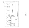
- FIG. 1 is a schematic diagram illustrating one exemplary embodiment of an Optical Transport Unit K (OTUK) frame 10 used in conjunction with the frame-interleaving systems and methods of the present invention.
- the OTUK frame 10 includes frame alignment (FAS) bytes 12, multi-frame alignment (MF) bytes 14, OTUK overhead (OH) bytes 16, Optical Data Unit K overhead (ODUK OH) bytes 18, Optical Payload Unit K overhead (OPUK OH) bytes 20, Optical Payload Unit (OPU) payload bytes 22, and FEC bytes 24 arranged over a plurality of rows 26 and columns 28.
- FES frame alignment
- MF multi-frame alignment
- OH OTUK overhead
- ODUK OH Optical Data Unit K overhead
- OPUK OH Optical Payload Unit K overhead
- OPU Optical Payload Unit
- FEC FEC bytes 24 arranged over a plurality of rows 26 and columns 28.
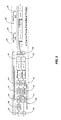
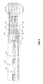
- FIG. 2 is a schematic diagram illustrating one exemplary embodiment of a two-channel frame-deinterleaving process 30 of the present invention.
- a client data signal 32 consisting of odd OTUK frames 34 (illustrated in white) and even OTUK frames 36 (illustrated in gray) is frame-deinterleaved into its constituent odd OTUK frames 34 and even OTUK frames 36 by a frame-deinterleaver 38.
- the odd frames 34 and even frames 36 are each FEC decoded by an FEC decoder 40, OH monitoring/termination/generation is performed by an OH monitor/terminator/generator 42, and FEC encoding is performed by an FEC encoder 44.
- the OH monitors/terminators/generators 42 share a communication path 46, such that OAM&P can be coordinated.
- a one-frame buffer 48 is inserted into the odd frame-path and channel 1 50, consisting of the odd frames 34, and channel 2 52, consisting of the even frames 36, result.
- This two-channel frame-deinterleaving process 30 is electrical throughout and each channel 50 and 52 can be transmitted over a single wavelength.
- This example can apply to any OTUK frame, but is especially applicable to OTU4 frames due to their relatively high data rate - with the high-data rate base signal being transmitted over two lower-data rate signals.
- FEC decoding/encoding and OH monitoring/termination/generation is correspondingly enabled in two lower-speed circuits.
- the MF bytes 14 ( FIG. 1 ) are used to select the odd/even frames 34 and 36 for the frame-deinterleave process 30, as well as to ensure proper frame ordering for the frame-interleave process 60 ( FIG. 3 ).
- the odd (even) frame bit parity overhead (BIP OH) applies to BIP errors over channel 1 (channel 2).
- FEC is terminated each frame.
- the OH in each frame is monitored for errors, faults, maintenance signals, and performance signals, and can be terminated/generated as required.
- multi-frame OAM&P can be coordinated between the two channels.
- larger interleave frame buffers can be used to accommodate large transport-induced skews between the two channels. Skews approaching 64 frames and larger can be accommodated by adding a secondary counter in unused OH that increments every full multi-frame, for example.
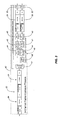
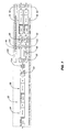
- FIG. 3 is a schematic diagram illustrating one exemplary embodiment of a two-channel frame-interleaving process 60 of the present invention.
- channel 1 50 consisting of the odd OTUK frames 34 (again illustrated in white)
- channel 2 52 consisting of the even OTUK frames 36 (again illustrated in gray)
- FEC decoder 40 OH monitoring/termination/generation is performed by an OH monitor/terminator/generator 42
- FEC encoding is performed by an FEC encoder 44.
- the OH monitors/terminators/generators 42 share a communication path 46, such that OAM&P can be coordinated.
- a one-frame buffer 48 is inserted into the even frame-path.
- the odd frames 34 and even frames 36 are frame-interleaved into the client data signal 32 by a frame-interleaver 62.
- this two-channel frame-interleaving process 60 is electrical throughout and each channel 50 and 52 can be transmitted over a single wavelength.
- This example can apply to any OTUK frame, but is especially applicable to OTU4 frames due to their relatively high data rate - with the high-data rate base signal being transmitted over two lower-data rate signals.
- FEC decoding/encoding and OH monitoring/termination/generation is correspondingly enabled in two lower-speed circuits.
- the MF bytes 14 ( FIG. 1 ) are used to select the odd/even frames 34 and 36 for the frame-deinterleave process 30 ( FIG. 2 ), as well as to ensure proper frame ordering for the frame-interleave process 60.
- the odd (even) frame BIP OH applies to BIP errors over channel 1 (channel 2).
- FEC is terminated each frame.
- the OH in each frame is monitored for errors, faults, maintenance signals, and performance signals, and can be terminated/generated as required.
- multi-frame OAM&P can be coordinated between the two channels.
- larger interleave frame buffers can be used to accommodate large transport-induced skews between the two channels. Skews approaching 64 frames and larger can be accommodated by adding a secondary counter in unused OH that increments every full multi-frame, for example.
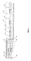
- FIG. 4 is a schematic diagram illustrating another exemplary embodiment of a two-channel frame-deinterleaving process 70 of the present invention - with most functionality partitioned to higher speed circuits.
- the client data signal 32 consisting of the odd OTUK frames 34 (again illustrated in white) and the even OTUK frames 36 (again illustrated in gray) is FEC decoded by an FEC decoder 40, OH monitoring/termination/generation is performed by an OH monitor/terminator/generator 42, and FEC encoding is performed by an FEC encoder 44.
- the client data signal 32 is frame-deinterleaved into its constituent odd OTUK frames 34 and even OTUK frames 36 by a frame-deinterleaver 38.
- a one-frame buffer 48 is inserted into the odd frame-path and channel 1 50, consisting of the odd frames 34, and channel 2 52, consisting of the even frames 36, result.
- FIG. 5 is a schematic diagram illustrating another exemplary embodiment of a two-channel frame-interleaving process 80 of the present invention - with base signal FEC partitioned to higher speed circuits.
- channel 1 50 consisting of the odd OTUK frames 34 (again illustrated in white)
- channel 2 52 consisting of the even OTUK frames 36 (again illustrated in gray)
- OH monitoring/termination/generation is performed by an OH monitor/terminator/generator 42.
- the OH monitors/terminators/generators 42 share a communication path 46, such that OAM&P can be coordinated.
- a one-frame buffer 48 is inserted into the even frame-path.
- the odd frames 34 and even frames 36 are frame-interleaved into the client data signal 32 by a frame-interleaver 62 and FEC encoding is performed by an FEC encoder 44.
- FIG. 6 is a schematic diagram illustrating a further exemplary embodiment of a two-channel frame-deinterleaving process 90 of the present invention - with transport signal FEC partitioned to lower speed circuits.
- the client data signal 32 consisting of the odd OTUK frames 34 (again illustrated in white) and the even OTUK frames 36 (again illustrated in gray) is FEC decoded by an FEC decoder 40 and OH monitoring/termination/generation is performed by an OH monitor/terminator/generator 42.
- the client data signal 32 is frame-deinterleaved into its constituent odd OTUK frames 34 and even OTUK frames 36 by a frame-deinterleaver 38.
- each of the odd frames 34 and even frames 36 are FEC encoded by an FEC encoder 44.
- a one-frame buffer 48 is inserted into the odd frame-path and channel 1 50, consisting of the odd frames 34, and channel 2 52, consisting of the even frames 36, result.
- FIG. 7 is a schematic diagram illustrating a further exemplary embodiment of a two-channel frame-interleaving process 100 of the present invention - with transport signal OH termination partitioned to lower speed circuits and base signal OH generation partitioned to higher speed circuits.
- channel 1 50 consisting of the odd OTUK frames 34 (again illustrated in white)
- channel 2 52 consisting of the even OTUK frames 36 (again illustrated in gray)
- OH termination is performed by an OH terminator 102.
- the OH terminators 102 share a communication path 46, such that OAM&P can be coordinated.
- a one-frame buffer 48 is inserted into the even frame-path.
- odd frames 34 and even frames 36 are frame-interleaved into the client data signal 32 by a frame-interleaver 62, OH generation is performed by an OH generator 104, and FEC encoding is performed by an FEC encoder 44.
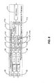
- FIG. 8 is a schematic diagram illustrating one exemplary embodiment of a Constant Bit Rate (CBR) client frame-deinterleaving process 110 of the present invention - with the CBR client mapped to two channels for transport.
- CBR Constant Bit Rate
- a CBR stream 111 consisting of a future odd frame portion (illustrated in white) and a future even frame portion (illustrated in gray) is frame-deinterleaved into odd OTUK frames 34 and even OTUK frames 36 by a payload frame-deinterleaver 112.
- a one-payload frame buffer 113 is inserted into the odd frame-path.
- each of the odd frames 34 and even frames 34 is ODUK mapped by an ODUK mapper 114, OH generation is performed by an OH generator 115, and FEC encoding is performed by an FEC encoder 116.
- the ODUK mappers 114 and OH generators 115 each share a communication path 118, such that OAM&P can be coordinated.
- the output is channel 1 50, consisting of the odd frames 34, and channel 2 52, consisting of the even frames 36.
- control of the payload frame-deinterleave/interleave and payload frame buffer operate with a constant relationship between the client bytes and transport bytes available. Functionality can be portioned to optimize the use of low-speed and high-speed circuits and supports different deinterleave/interleave partitioning.
- control of the payload frame-deinterleave/interleave and payload frame buffer adjust timing an buffer size according to the applicable justification requirements between the client bytes and transport bytes available.
- control of the payload frame-deinterleave/interleave and payload frame buffer operate with a constant relationship between the GFP bytes and transport bytes available.
- a GFP mapper adjusts between the GFP bytes available and the client bytes.
- FIG. 9 is a schematic diagram illustrating one exemplary embodiment of a CBR client frame-interleaving process 120 of the present invention - with the CBR client demapped from two channels for transport.
- channel 1 50 consisting of the odd OTUK frames 34 (again illustrated in white)
- channel 2 52 consisting of the even OTUK frames 36 (again illustrated in gray)
- FEC decoder 121 is each FEC decoded by an FEC decoder 121
- OH termination is performed by an OH terminator 122
- ODUK demapping is performed by an ODUK demapper 123.
- the OH terminators 122 and ODUK demappers 123 each share a communication path 118, such that OAM&P can be coordinated.
- a one-payload frame buffer 124 is inserted into the even frame-path.
- the odd frames 34 and even frames 36 are frame-interleaved into the CBR stream 111 by a payload frame-interleaver 125.
- control of the payload frame-deinterleave/interleave and payload frame buffer operate with a constant relationship between the client bytes and transport bytes available.
- Functionality can be portioned to optimize the use of low-speed and high-speed circuits and supports different deinterleave/interleave partitioning.
- control of the payload frame-deinterleave/interleave and payload frame buffer adjust timing an buffer size according to the applicable justification requirements between the client bytes and transport bytes available.
- control of the payload frame-deinterleave/interleave and payload frame buffer operate with a constant relationship between the GFP bytes and transport bytes available.
- a GFP mapper adjusts between the GFP bytes available and the client bytes.
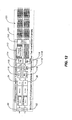
- FIG. 10 is a schematic diagram illustrating one exemplary embodiment of a client signal frame-deinterleaving process 130 of the present invention - with the client signal GFP mapped to two channels for transport.
- a client signal 131 consisting of a future odd frame portion (again illustrated in white) and a future even frame portion (again illustrated in gray) is frame-deinterleaved into odd OTUK frames 34 and even OTUK frames 36 by a payload frame-deinterleaver 112.
- each of the odd and even streams is GFP mapped by a GFP mapper 132.
- a one-payload frame buffer 113 is inserted into the odd frame-path.
- each of the odd frames 34 and even frames 34 is ODUK mapped by an ODUK mapper 114, OH generation is performed by an OH generator 115, and FEC encoding is performed by an FEC encoder 116.
- the GFP mappers 132 and OH generators 115 each share a communication path 118, such that OAM&P can be coordinated.
- the output is channel 1 50, consisting of the odd frames 34, and channel 2 52, consisting of the even frames 36.
- FIG. 11 is a schematic diagram illustrating one exemplary embodiment of a client signal frame-interleaving process 140 of the present invention - with the client signal GFP demapped from two channels for transport.
- channel 1 50 consisting of the odd OTUK frames 34 (again illustrated in white)
- channel 2 52 consisting of the even OTUK frames 36 (again illustrated in gray)
- FEC decoder 121 is each FEC decoded by an FEC decoder 121
- OH termination is performed by an OH terminator 122
- ODUK demapping is performed by an ODUK demapper 123.
- a one-payload frame buffer 124 is inserted into the even frame-path.
- each of the odd and even streams is GFP demapped by a GFP demapper 141.
- the OH terminators 122 and GFP demappers 141 each share a communication path 118, such that OAM&P can be coordinated.
- the odd frames 34 and even frames 36 are frame-interleaved into the client signal 131 by a payload frame-interleaver 125.
- FIG. 12 is a schematic diagram illustrating one exemplary embodiment of a 10-client OTU4-compliant multiplexer transported over two interleaved channels in accordance with the systems and methods 150 of the present invention.
- an N-client stream 151 consisting of a future odd frame portion (illustrated in white) and a future even frame portion (illustrated in gray) is interleaved into odd OTUK frames 34 and even OTUK frames 36 by an ODU2E4 interleaver 152.
- a one-payload frame buffer 113 is inserted into the odd frame-path.
- each of the odd frames 34 and even frames 34 is ODUK mapped by an ODUK mapper 114, OH generation is performed by an OH generator 115, and FEC encoding is performed by an FEC encoder 116.
- the ODUK mappers 114 and OH generators 115 each share a communication path 118, such that OAM&P can be coordinated.
- the output is channel 1 50, consisting of the odd frames 34, and channel 2 52, consisting of the even frames 36.
- This process 150 could apply to 10x or 2 N clients multiplexed into an OTU4, for example.
- Exemplary clients include 10GbE LAN, 10GbE WAN, 10GbE GFP mapped, OC192, OTU2, OTU2E, ODU2 LAN, and combinations thereof.
- the functionality can be apportioned to optimize the use of low-speed and high-speed circuits and supports differing deinterleaving and interleaving partitioning.
- An OTU4-compatible process 150 produces an OTU4 stream with 10 tribs multiplexed into each frame, but requires payload coordination between channels.
- a non-compatible process 160 ( FIG.
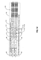
- FIG. 13 is a schematic diagram illustrating one exemplary embodiment of a 10-client OTU4-compliant demultiplexer transported over two interleaved channels in accordance with the systems and methods 160 of the present invention.
- channel 1 50 consisting of the odd OTUK frames 34 (again illustrated in white)
- channel 2 52 consisting of the even OTUK frames 36 (again illustrated in gray)
- FEC decoder 121 is each FEC decoded by an FEC decoder 121
- OH termination is performed by an OH terminator 122
- ODUK demapping is performed by an ODUK demapper 123.
- the OH terminators 122 and ODUK demappers 123 each share a communication path 118, such that OAM&P can be coordinated.
- a one-payload frame buffer 124 is inserted into the even frame-path.
- the odd frames 34 and even frames 36 are deinterleaved into the N-client stream 151 by an ODU2E4 deinterleaver 161.
- this process 160 could apply to 10x or 2 N clients multiplexed into an OTU4, for example.
- Exemplary clients include 10GbE LAN, 10GbE WAN, 10GbE GFP mapped, OC192, OTU2, OTU2E, ODU2 LAN, and combinations thereof.
- the functionality can be apportioned to optimize the use of low-speed and high-speed circuits and supports differing deinterleaving and interleaving partitioning.
- An OTU4-compatible process 150 ( FIG.
- a non-compatible process 160 results in OTU4 frames with the first 5 tribs multiplexed into odd frames and the second 5 tribs multiplexed into even frames, creating two 5-trib multiplexing framers but not requiring interleave/deinterleave.
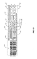
- FIG. 14 is a schematic diagram illustrating one exemplary embodiment of a 10-client non-compliant multiplexer transported over two individual channels in accordance with the systems and methods 170 of the present invention.
- an N-client stream 151 consisting of a future odd frame portion (again illustrated in white) and a future even frame portion (again illustrated in gray) is received.
- a one-payload frame buffer 113 is inserted into the odd frame-path.
- each of the odd frames 34 and even frames 34 is ODUK mapped by an ODUK mapper 114, OH generation is performed by an OH generator 115, and FEC encoding is performed by an FEC encoder 116.
- the ODUK mappers 114 and OH generators 115 each share a communication path 118, such that OAM&P can be coordinated.
- the output is channel 1 50, consisting of the odd frames 34, and channel 2 52, consisting of the even frames 36.
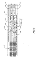
- FIG. 15 is a schematic diagram illustrating one exemplary embodiment of a 10-client non-compliant demultiplexer transported over two individual channels in accordance with the systems and methods 180 of the present invention.
- channel 1 50 consisting of the odd OTUK frames 34 (again illustrated in white)
- channel 2 52 consisting of the even OTUK frames 36 (again illustrated in gray)
- FEC decoder 121 is each FEC decoded by an FEC decoder 121
- OH termination is performed by an OH terminator 122
- ODUK demapping is performed by an ODUK demapper 123.
- the OH terminators 122 and ODUK demappers 123 each share a communication path 118, such that OAM&P can be coordinated.
- a one-payload frame buffer 124 is inserted into the even frame-path.
- the N-client stream 151 is output.
Landscapes
- Engineering & Computer Science (AREA)
- Computer Networks & Wireless Communication (AREA)
- Signal Processing (AREA)
- Microelectronics & Electronic Packaging (AREA)
- Detection And Prevention Of Errors In Transmission (AREA)
- Time-Division Multiplex Systems (AREA)
- Error Detection And Correction (AREA)
- Optical Communication System (AREA)
Abstract
Description
- The present invention relates generally to the optical networking field. More specifically, the preferred embodiment relates to frame-interleaving systems and methods for Optical Transport Unit K (OTUK) (i.e. Optical Transport Unit 4 (OTU4)), 100Gb/s Ethernet (100GbE), and other 100Gb/s (100G) optical transport enabling multi-level optical transmission. The frame-interleaving systems and methods of the present invention support the multiplexing of sub-rate clients, such as 10x10Gb/s (10G) clients, 2x40Gb/s (40G) plus 2x10G clients, etc., into two 50Gb/s (50G) transport signals, four 25Gb/s (25G) transport signals, etc. that are forward error correction (FEC) encoded and carried on a single wavelength to provide useful, efficient, and cost-effective 100G optical transport solutions today. In one exemplary configuration, a 100G client signal or 100G aggregate client signal carried over two or more channels is frame-deinterleaved, followed by even/odd sub-channel FEC encoding and framing. In another exemplary configuration, a 100G client signal or 100G aggregate client signal carried over two or more channels is received and processed by a single 100G FEC framer, followed by frame-deinterleaving into two or more sub-rate channels.
- At present, state-of-the-art 100Gb/s (100G) optical transport work is occurring in two areas: 1) transmission and modulation format development and 2) framing and standards body work required to define 100G optical transport framing and multiplexing standards. Transmission and modulation format development falls into two categories: 1) 100G serial optical transmission as demonstrated by network gear providers and other researchers performing 100G optical transmission "hero" experiments, which focus on the accumulation of knowledge but not necessarily efficiency or cost-effectiveness, and 2) realistic transmission and modulation schemes that are based on present and future optical and electronic technologies, which typically involve transmission and modulation schemes that attempt to provide greater spectral efficiency, solve dispersion problems, and limit baud rates by providing multiple bits-per-symbol encodings and/or by using enhanced forward error correction (FEC) schemes, such as duo-binary modulation, Differential Phase Shift Keying (DPSK), Differential Quadrature Phase Shift Keying (DQPSK), and the like.
- In general, standards bodies are looking several years into the future to define framing formats (i.e. Optical Transport Unit 4 (OTU4) in International Telecommunications Union (ITU-T) Study Group 15), backplane interface standards, and multiplexing schemes, which are unrealizable for 100G optical transport today but will become feasible in the future. Thus, for network providers that desire 100G optical transport solutions sooner rather than later, a disconnect exists.
- At present, state-of-the-art 100G optical transmission systems/methods do not exist in deployed networks. They are, however, actively being researched and designed to address the need for ever-increasing packet bandwidth and logical flow requirements. Long-haul 100G serial optical transmission is possible but very unrealistic today given present optical and electronic technologies, and the same is true for the foreseeable future. Coupled with the forthcoming OTU4 100G optical framing standard, the stage is set for present optical and electronic technologies to fall short in delivering an efficient and cost-effective 100G optical transport system that suits the needs of today's bandwidth-hungry network providers. Thus, what is needed in the art is an approach that preserves standard framing formats and interoperability while enabling spectrally efficient 100G optical transport today.
- The present invention relates to a transport method as claimed in
claims 1, 9 and 19 and a transport system as claimed inclaim - In various exemplary embodiments, the preferred embodiment provides frame-interleaving systems and methods for Optical Transport Unit K (OTUK) (i.e. Optical Transport Unit 4 (OTU4)), 100Gb/s Ethernet (100GbE), and other 100Gb/s (100G) optical transport enabling multi-level optical transmission. The frame-interleaving systems and methods of the present invention support the multiplexing of sub-rate clients, such as 10x10Gb/s (10G) clients, 2x40Gb/s (40G) plus 2x10G clients, etc., into two 50Gb/s (50G) transport signals, four 25Gb/s (25G) transport signals, etc. that are forward error correction (FEC) encoded and carried on a single wavelength to provide useful, efficient, and cost-effective 100G optical transport solutions today. In one exemplary configuration, a 100G client signal or 100G aggregate client signal carried over two or more channels is frame-deinterleaved, followed by even/odd sub-channel FEC encoding and framing. In another exemplary configuration, a 100G client signal or 100G aggregate client signal carried over two or more channels is received and processed by a single 100G FEC framer, followed by frame-deinterleaving into two or more sub-rate channels. Advantageously, the frame-interleaving systems and methods of the present invention can be implemented in digital circuitry (i.e. a field-programmable gate array (FPGA) or the like) available today.
- In one exemplary embodiment, the present invention provides a transport method, including: receiving an aggregate client signal; and deinterleaving the aggregate client signal across N paths, each of the N paths carrying one of every N frames into which the aggregate client signal is deinterleaved. Each of the N paths include a set of Optical Transport Network (OTN) overhead for individual path operations, administration, maintenance, and provisioning (OAM&P). Each of the N paths also include a set of Optical Transport Network (OTN) overhead for coordinated path operations, administration, maintenance, and provisioning (OAM&P). The transport method also includes performing forward error correction (FEC) decoding for each of the N paths one of prior to and subsequent to deinterleaving, performing overhead monitoring/termination/generation for each of the N paths one of prior to and subsequent to deinterleaving, performing forward error correction (FEC) encoding for each of the N paths one of prior to and subsequent to deinterleaving, performing Optical Data Unit K (ODUK) mapping for each of the N paths subsequent to deinterleaving, performing Generic Framing Protocol (GFP) mapping for each of the N paths subsequent to deinterleaving, and/or inserting one or more frame buffers into selected paths of the N paths subsequent to deinterleaving. The aggregate client signal consists of an aggregate client signal selected from the group consisting of an Optical Transport Unit 4 (OTU4) client signal, an Optical Transport Unit K (OTUK) client signal, a constant bit rate (CBR) client signal, a 100Gb/s (100G) client signal, a 100Gb/s Ethernet (100GbE) Local Area Network (LAN) client signal, a 100Gb/s Ethernet (100GbE) Wide Area Network (WAN) client signal, a 100Gb/s Ethernet (100GbE) Generic Framing Protocol (GFP)-mapped client signal, a 10Gb/s Ethernet (10GbE) client signal, an Optical Channel 192 (OC192) client signal, an Optical Transport Unit 2 (OTU2) client signal, an Optical Transport Unit 2E (OTU2E) client signal, an Optical Data Unit 2 (ODU2) client signal, an Optical Data Unit 2 (ODU2) Local Area Network (LAN) (ODU2L) client signal, a subset thereof, an aggregation thereof, and a combination thereof. The N frames consist of OTUK frames.
- In another exemplary embodiment, the present invention provides a transport method, including: receiving N transport signals distributed across N paths; and interleaving the N transport signals to form an aggregate client signal, each of the N paths carrying one of every N frames from which the aggregate client signal is interleaved. Each of the N paths includes a set of Optical Transport Network (OTN) overhead for individual path operations, administration, maintenance, and provisioning (OAM&P). Each of the N paths also include a set of Optical Transport Network (OTN) overhead for coordinated path operations, administration, maintenance, and provisioning (OAM&P). The transport method also includes performing forward error correction (FEC) decoding for each of the N paths prior to interleaving, performing overhead monitoring/termination/generation for each of the N paths one of prior to and subsequent to interleaving, performing forward error correction (FEC) encoding for each of the N paths one of prior to and subsequent to interleaving, performing Optical Data Unit K (ODUK) demapping for each of the N paths prior to interleaving, performing Generic Framing Protocol (GFP) demapping for each of the N paths prior to interleaving, and/or inserting one or more frame buffers into selected paths of the N paths prior to interleaving. The aggregate client signal consists of an aggregate client signal selected from the group consisting of an Optical Transport Unit 4 (OTU4) client signal, an Optical Transport Unit K (OTUK) client signal, a constant bit rate (CBR) client signal, a 100Gb/s (100G) client signal, a 100Gb/s Ethernet (100GbE) Local Area Network (LAN) client signal, a 100Gb/s Ethernet (100GbE) Wide Area Network (WAN) client signal, a 100Gb/s Ethernet (100GbE) Generic Framing Protocol (GFP)-mapped client signal, a 10Gb/s Ethernet (10GbE) client signal, an Optical Channel 192 (OC192) client signal, an Optical Transport Unit 2 (OTU2) client signal, an Optical Transport Unit 2E (OTU2E) client signal, an Optical Data Unit 2 (ODU2) client signal, an Optical Data Unit 2 (ODU2) Local Area Network (LAN) (ODU2L) client signal, a subset thereof, an aggregation thereof, and a combination thereof. The N frames consist of OTUK frames.
- In a further exemplary embodiment, the present invention provides transport system, including: one or more inputs for receiving an aggregate client signal; and a deinterleaver for deinterleaving the aggregate client signal across N paths, each of the N paths carrying one of every N frames into which the aggregate client signal is deinterleaved.
- In a still further exemplary embodiment, the present provides a transport system, including: one or more inputs for receiving N transport signals distributed across N paths; and an interleaver for interleaving the N transport signals to form an aggregate client signal, each of the N paths carrying one of every N frames from which the aggregate client signal is interleaved.
- In a still further exemplary embodiment, the present provides a transport method, including: transporting one of every N frames associated with an aggregate client signal over a selected one of N channels; wherein each of the N channels include a set of Optical Transport Network (OTN) overhead for individual path operations, administration, maintenance, and provisioning (OAM&P); and wherein each of the N channels include a set of Optical Transport Network (OTN) overhead for coordinated path operations, administration, maintenance, and provisioning (OAM&P).
- The preferred embodiment is illustrated and described herein with reference to the various drawings, in which like reference numbers are used to denote like system components/method steps, as appropriate, and in which:
-
FIG. 1 is a schematic diagram illustrating one exemplary embodiment of an Optical Transport Unit K (OTUK) frame used in conjunction with the frame-interleaving systems and methods of the present invention; -
FIG. 2 is a schematic diagram illustrating one exemplary embodiment of a two-channel frame-deinterleaving process of the present invention; -
FIG. 3 is a schematic diagram illustrating one exemplary embodiment of a two-channel frame-interleaving process of the present invention; -
FIG. 4 is a schematic diagram illustrating another exemplary embodiment of a two-channel frame-deinterleaving process of the present invention - with most functionality partitioned to higher speed circuits; -
FIG. 5 is a schematic diagram illustrating another exemplary embodiment of a two-channel frame-interleaving process of the present invention - with base signal forward error correction (FEC) partitioned to higher speed circuits; -
FIG. 6 is a schematic diagram illustrating a further exemplary embodiment of a two-channel frame-deinterleaving process of the present invention - with transport signal FEC partitioned to lower speed circuits; -
FIG. 7 is a schematic diagram illustrating a further exemplary embodiment of a two-channel frame-interleaving process of the present invention - with transport signal overhead (OH) termination partitioned to lower speed circuits and base signal OH generation partitioned to higher speed circuits; -
FIG. 8 is a schematic diagram illustrating one exemplary embodiment of a Constant Bit Rate (CBR) client frame-deinterleaving process of the present invention - with the CBR client mapped to two channels for transport; -
FIG. 9 is a schematic diagram illustrating one exemplary embodiment of a CBR client frame-interleaving process of the present invention - with the CBR client demapped from two channels for transport; -
FIG. 10 is a schematic diagram illustrating one exemplary embodiment of a client signal frame-deinterleaving process of the present invention - with the client signal Generic Framing Protocol (GFP) mapped to two channels for transport; -
FIG. 11 is a schematic diagram illustrating one exemplary embodiment of a client signal frame-interleaving process of the present invention - with the client signal GFP demapped from two channels for transport; -
FIG. 12 is a schematic diagram illustrating one exemplary embodiment of a 10-client OTU4-compliant multiplexer transported over two interleaved channels.in accordance with the systems and methods of the present invention; -
FIG. 13 is a schematic diagram illustrating one exemplary embodiment of a 10-client OTU4-compliant demultiplexer transported over two interleaved channels in accordance with the systems and methods of the present invention; -
FIG. 14 is a schematic diagram illustrating one exemplary embodiment of a 10-client non-compliant multiplexer transported over two individual channels in accordance with the systems and methods of the present invention; and -
FIG. 15 is a schematic diagram illustrating one exemplary embodiment of a 10-client non-compliant demultiplexer transported over two individual channels in accordance with the systems and methods of the present invention. - Again, the present invention provides frame-interleaving systems and methods for Optical Transport Unit K (OTUK) (i.e. Optical Transport Unit 4 (OTU4)), 100Gb/s Ethernet (100GbE), and other 100Gb/s (100G) optical transport enabling multi-level optical transmission. The frame-interleaving systems and methods of the present invention support the multiplexing of sub-rate clients, such as 10x10Gb/s (10G) clients, 2x40Gb/s (40G) plus 2x10G clients, etc., into two 50Gb/s (50G) transport signals, four 25Gb/s (25G) transport signals, etc. that are forward error correction (FEC) encoded and carried on a single wavelength to provide useful, efficient, and cost-effective 100G optical transport solutions today. In one exemplary configuration, a 100G client signal or 100G aggregate client signal carried over two or more channels is frame-deinterleaved, followed by even/odd sub-channel FEC encoding and framing. In another exemplary configuration, a 100G client signal or 100G aggregate client signal carried over two or more channels is received and processed by a single 100G FEC framer, followed by frame-deinterleaving into two or more sub-rate channels. Advantageously, the frame-interleaving systems and methods of the present invention can be implemented in digital circuitry (i.e. a field-programmable gate array (FPGA) or the like) available today. The frame-interleaving approach of the present invention is particularly applicable to the sub-rate multiplexing of multiple sub-rate client signals into a 100G transport signals, or a 2x50G or 4x25G architecture.
- At present, serial 100G optical transmission is not feasible from a performance and cost standpoint. However, 100G optical transmission is very feasible if alternate modulation schemes are used to improve the spectral efficiency and baud rate of the optical transmission, without compromising the overall throughput or regenerated distance limits. Modulation schemes, such as Return-to-Zero-Differential Quadrature Phase Shift Keying (RZ-DQPSK) and the like, allow for multiple bits per symbol, and also allow for a 100G logical flow to be broken into 2x50G or 4x25G logical flows for processing using electronic components available today. If a modulation scheme is developed that allows a 100G OTU4-framed signal (the proposed International Telecommunications Union (ITU-T) transport framing standard for 100G optical transmission) to be carried seamlessly by spectrally efficient means, using today's electronic components, this would allow for a much more cost-efficient deployment of 100G optical transport gear. This would occur much sooner than serial 100G optical transmission, while providing for much greater distance performance without compromising client-side interoperability or requiring exotic electronic component development.
- 100G transponder and multiplexing transponder (MUXPONDER) applications are vital in long haul optical transport networks as optical fiber bandwidth continues to be absorbed by voice, video, and other data-centric applications, first in highly populated urban networks, and eventually in worldwide networks. Single wavelength, spectrally efficient transport techniques solve this problem without compromising regeneration distances.
- In general, the frame-interleaving systems and methods of the present invention deinterleave OTU4 frames across N paths (where N = 2, 4, 8, etc.). Each path carries one of every N frames. For the two-path (i.e. N = 2) case, for example, each path carries one-half of the frames - one path carrying the odd frames and the other path carrying the even frames. Each path contains a full set of Optical Transport Network (OTN) overhead allowing for individual path operations, administration, maintenance, and provisioning (OAM&P), as well as combined OAM&P. For example, each path can be individually framed, FEC encoded/decoded, monitored for an alarm indication signal (AIS), an open connection indication (OCI), a locked (LCK) state, and a backwards defect indication (BDI). In the two-path (i.e. N = 2) implementation, each path can be monitored individually for bit errors because an OTN bit parity (BIP) is calculated over the current frame and inserted two frames later. Thus, deinterleaving as applied to client mapping and multiplexing allows a client signal to be mapped directly into the deinterleaved frames instead of having to map/multiplex directly into a single high-speed payload.
-
FIG. 1 is a schematic diagram illustrating one exemplary embodiment of an Optical Transport Unit K (OTUK)frame 10 used in conjunction with the frame-interleaving systems and methods of the present invention. As will be readily apparent to those of ordinary skill in the art, theOTUK frame 10 includes frame alignment (FAS) bytes 12, multi-frame alignment (MF) bytes 14, OTUK overhead (OH) bytes 16, Optical Data Unit K overhead (ODUK OH) bytes 18, Optical Payload Unit K overhead (OPUK OH) bytes 20, Optical Payload Unit (OPU)payload bytes 22, and FEC bytes 24 arranged over a plurality ofrows 26 andcolumns 28. -
FIG. 2 is a schematic diagram illustrating one exemplary embodiment of a two-channel frame-deinterleaving process 30 of the present invention. First, a client data signal 32 consisting of odd OTUK frames 34 (illustrated in white) and even OTUK frames 36 (illustrated in gray) is frame-deinterleaved into its constituent odd OTUK frames 34 and even OTUK frames 36 by a frame-deinterleaver 38. Next, theodd frames 34 and even frames 36 are each FEC decoded by anFEC decoder 40, OH monitoring/termination/generation is performed by an OH monitor/terminator/generator 42, and FEC encoding is performed by anFEC encoder 44. Preferably, the OH monitors/terminators/generators 42 share acommunication path 46, such that OAM&P can be coordinated. Finally, a one-frame buffer 48 is inserted into the odd frame-path andchannel 1 50, consisting of theodd frames 34, andchannel 2 52, consisting of the even frames 36, result. This two-channel frame-deinterleaving process 30 is electrical throughout and eachchannel FIG. 1 ) are used to select the odd/even frames 34 and 36 for the frame-deinterleave process 30, as well as to ensure proper frame ordering for the frame-interleave process 60 (FIG. 3 ). The odd (even) frame bit parity overhead (BIP OH) applies to BIP errors over channel 1 (channel 2). Preferably, FEC is terminated each frame. The OH in each frame is monitored for errors, faults, maintenance signals, and performance signals, and can be terminated/generated as required. Advantageously, multi-frame OAM&P can be coordinated between the two channels. Finally, larger interleave frame buffers can be used to accommodate large transport-induced skews between the two channels. Skews approaching 64 frames and larger can be accommodated by adding a secondary counter in unused OH that increments every full multi-frame, for example. -
FIG. 3 is a schematic diagram illustrating one exemplary embodiment of a two-channel frame-interleavingprocess 60 of the present invention. First,channel 1 50, consisting of the odd OTUK frames 34 (again illustrated in white), andchannel 2 52, consisting of the even OTUK frames 36 (again illustrated in gray), are each FEC decoded by anFEC decoder 40, OH monitoring/termination/generation is performed by an OH monitor/terminator/generator 42, and FEC encoding is performed by anFEC encoder 44. Preferably, the OH monitors/terminators/generators 42 share acommunication path 46, such that OAM&P can be coordinated. Next, a one-frame buffer 48 is inserted into the even frame-path. Finally, theodd frames 34 and even frames 36 are frame-interleaved into the client data signal 32 by a frame-interleaver 62. Again, this two-channel frame-interleavingprocess 60 is electrical throughout and eachchannel FIG. 1 ) are used to select the odd/even frames 34 and 36 for the frame-deinterleave process 30 (FIG. 2 ), as well as to ensure proper frame ordering for the frame-interleave process 60. The odd (even) frame BIP OH applies to BIP errors over channel 1 (channel 2). Preferably, FEC is terminated each frame. The OH in each frame is monitored for errors, faults, maintenance signals, and performance signals, and can be terminated/generated as required. Advantageously, multi-frame OAM&P can be coordinated between the two channels. Finally, larger interleave frame buffers can be used to accommodate large transport-induced skews between the two channels. Skews approaching 64 frames and larger can be accommodated by adding a secondary counter in unused OH that increments every full multi-frame, for example. -
FIG. 4 is a schematic diagram illustrating another exemplary embodiment of a two-channel frame-deinterleaving process 70 of the present invention - with most functionality partitioned to higher speed circuits. First, the client data signal 32 consisting of the odd OTUK frames 34 (again illustrated in white) and the even OTUK frames 36 (again illustrated in gray) is FEC decoded by anFEC decoder 40, OH monitoring/termination/generation is performed by an OH monitor/terminator/generator 42, and FEC encoding is performed by anFEC encoder 44. Next, the client data signal 32 is frame-deinterleaved into its constituent odd OTUK frames 34 and even OTUK frames 36 by a frame-deinterleaver 38. Finally, a one-frame buffer 48 is inserted into the odd frame-path andchannel 1 50, consisting of theodd frames 34, andchannel 2 52, consisting of the even frames 36, result. -
FIG. 5 is a schematic diagram illustrating another exemplary embodiment of a two-channel frame-interleavingprocess 80 of the present invention - with base signal FEC partitioned to higher speed circuits. First,channel 1 50, consisting of the odd OTUK frames 34 (again illustrated in white), andchannel 2 52, consisting of the even OTUK frames 36 (again illustrated in gray), are each FEC decoded by anFEC decoder 40 and OH monitoring/termination/generation is performed by an OH monitor/terminator/generator 42. Preferably, the OH monitors/terminators/generators 42 share acommunication path 46, such that OAM&P can be coordinated. Next, a one-frame buffer 48 is inserted into the even frame-path. Finally, theodd frames 34 and even frames 36 are frame-interleaved into the client data signal 32 by a frame-interleaver 62 and FEC encoding is performed by anFEC encoder 44. -
FIG. 6 is a schematic diagram illustrating a further exemplary embodiment of a two-channel frame-deinterleaving process 90 of the present invention - with transport signal FEC partitioned to lower speed circuits. First, the client data signal 32 consisting of the odd OTUK frames 34 (again illustrated in white) and the even OTUK frames 36 (again illustrated in gray) is FEC decoded by anFEC decoder 40 and OH monitoring/termination/generation is performed by an OH monitor/terminator/generator 42. Next, the client data signal 32 is frame-deinterleaved into its constituent odd OTUK frames 34 and even OTUK frames 36 by a frame-deinterleaver 38. Subsequently, each of theodd frames 34 and even frames 36 are FEC encoded by anFEC encoder 44. Finally, a one-frame buffer 48 is inserted into the odd frame-path andchannel 1 50, consisting of theodd frames 34, andchannel 2 52, consisting of the even frames 36, result. -
FIG. 7 is a schematic diagram illustrating a further exemplary embodiment of a two-channel frame-interleaving process 100 of the present invention - with transport signal OH termination partitioned to lower speed circuits and base signal OH generation partitioned to higher speed circuits. First,channel 1 50, consisting of the odd OTUK frames 34 (again illustrated in white), andchannel 2 52, consisting of the even OTUK frames 36 (again illustrated in gray), are each FEC decoded by anFEC decoder 40 and OH termination is performed by anOH terminator 102. Preferably, theOH terminators 102 share acommunication path 46, such that OAM&P can be coordinated. Next, a one-frame buffer 48 is inserted into the even frame-path. Finally, theodd frames 34 and even frames 36 are frame-interleaved into the client data signal 32 by a frame-interleaver 62, OH generation is performed by anOH generator 104, and FEC encoding is performed by anFEC encoder 44. -
FIG. 8 is a schematic diagram illustrating one exemplary embodiment of a Constant Bit Rate (CBR) client frame-deinterleaving process 110 of the present invention - with the CBR client mapped to two channels for transport. First, aCBR stream 111 consisting of a future odd frame portion (illustrated in white) and a future even frame portion (illustrated in gray) is frame-deinterleaved into odd OTUK frames 34 and even OTUK frames 36 by a payload frame-deinterleaver 112. Next, a one-payload frame buffer 113 is inserted into the odd frame-path. Subsequently, each of theodd frames 34 and even frames 34 is ODUK mapped by anODUK mapper 114, OH generation is performed by anOH generator 115, and FEC encoding is performed by anFEC encoder 116. Preferably, theODUK mappers 114 andOH generators 115 each share acommunication path 118, such that OAM&P can be coordinated. The output ischannel 1 50, consisting of theodd frames 34, andchannel 2 52, consisting of the even frames 36. Thisprocess 110 could apply to any client signal mapped into an OTU4 frame, such as a 100GbE client signal at 103.125Gb/s, a 100GbE client signal that is FEC decoded and Generic Framing Protocol (GFP) mapped, etc. It can be extended to OTU4 over 2N channels, where N = 1, 2, etc. For synchronized CBR mappings, control of the payload frame-deinterleave/interleave and payload frame buffer operate with a constant relationship between the client bytes and transport bytes available. Functionality can be portioned to optimize the use of low-speed and high-speed circuits and supports different deinterleave/interleave partitioning. For asynchronous CBR mappings, control of the payload frame-deinterleave/interleave and payload frame buffer adjust timing an buffer size according to the applicable justification requirements between the client bytes and transport bytes available. For GFP mappings, control of the payload frame-deinterleave/interleave and payload frame buffer operate with a constant relationship between the GFP bytes and transport bytes available. A GFP mapper adjusts between the GFP bytes available and the client bytes. -
FIG. 9 is a schematic diagram illustrating one exemplary embodiment of a CBR client frame-interleaving process 120 of the present invention - with the CBR client demapped from two channels for transport. First,channel 1 50, consisting of the odd OTUK frames 34 (again illustrated in white), andchannel 2 52, consisting of the even OTUK frames 36 (again illustrated in gray), are each FEC decoded by anFEC decoder 121, OH termination is performed by anOH terminator 122, and ODUK demapping is performed by anODUK demapper 123. Preferably, theOH terminators 122 andODUK demappers 123 each share acommunication path 118, such that OAM&P can be coordinated. Next, a one-payload frame buffer 124 is inserted into the even frame-path. Finally, theodd frames 34 and even frames 36 are frame-interleaved into theCBR stream 111 by a payload frame-interleaver 125. Again, thisprocess 120 could apply to any client signal mapped into an OTU4 frame, such as a 100GbE client signal at 103.125Gb/s, a 100GbE client signal that is FEC decoded and GFP mapped, etc. It can be extended to OTU4 over 2N channels, where N = 1, 2, etc. For synchronized CBR mappings, control of the payload frame-deinterleave/interleave and payload frame buffer operate with a constant relationship between the client bytes and transport bytes available. Functionality can be portioned to optimize the use of low-speed and high-speed circuits and supports different deinterleave/interleave partitioning. For asynchronous CBR mappings, control of the payload frame-deinterleave/interleave and payload frame buffer adjust timing an buffer size according to the applicable justification requirements between the client bytes and transport bytes available. For GFP mappings, control of the payload frame-deinterleave/interleave and payload frame buffer operate with a constant relationship between the GFP bytes and transport bytes available. A GFP mapper adjusts between the GFP bytes available and the client bytes. -
FIG. 10 is a schematic diagram illustrating one exemplary embodiment of a client signal frame-deinterleaving process 130 of the present invention - with the client signal GFP mapped to two channels for transport. First, aclient signal 131 consisting of a future odd frame portion (again illustrated in white) and a future even frame portion (again illustrated in gray) is frame-deinterleaved into odd OTUK frames 34 and even OTUK frames 36 by a payload frame-deinterleaver 112. Next, each of the odd and even streams is GFP mapped by aGFP mapper 132. Next, a one-payload frame buffer 113 is inserted into the odd frame-path. Subsequently, each of theodd frames 34 and even frames 34 is ODUK mapped by anODUK mapper 114, OH generation is performed by anOH generator 115, and FEC encoding is performed by anFEC encoder 116. Preferably, theGFP mappers 132 andOH generators 115 each share acommunication path 118, such that OAM&P can be coordinated. The output ischannel 1 50, consisting of theodd frames 34, andchannel 2 52, consisting of the even frames 36. -
FIG. 11 is a schematic diagram illustrating one exemplary embodiment of a client signal frame-interleaving process 140 of the present invention - with the client signal GFP demapped from two channels for transport. First,channel 1 50, consisting of the odd OTUK frames 34 (again illustrated in white), andchannel 2 52, consisting of the even OTUK frames 36 (again illustrated in gray), are each FEC decoded by anFEC decoder 121, OH termination is performed by anOH terminator 122, and ODUK demapping is performed by anODUK demapper 123. Next, a one-payload frame buffer 124 is inserted into the even frame-path. Next, each of the odd and even streams is GFP demapped by aGFP demapper 141. Preferably, theOH terminators 122 andGFP demappers 141 each share acommunication path 118, such that OAM&P can be coordinated. Finally, theodd frames 34 and even frames 36 are frame-interleaved into theclient signal 131 by a payload frame-interleaver 125. -
FIG. 12 is a schematic diagram illustrating one exemplary embodiment of a 10-client OTU4-compliant multiplexer transported over two interleaved channels in accordance with the systems and methods 150 of the present invention. First, an N-client stream 151 consisting of a future odd frame portion (illustrated in white) and a future even frame portion (illustrated in gray) is interleaved into odd OTUK frames 34 and even OTUK frames 36 by an ODU2E4 interleaver 152. Next, a one-payload frame buffer 113 is inserted into the odd frame-path. Subsequently, each of theodd frames 34 and even frames 34 is ODUK mapped by anODUK mapper 114, OH generation is performed by anOH generator 115, and FEC encoding is performed by anFEC encoder 116. Preferably, theODUK mappers 114 andOH generators 115 each share acommunication path 118, such that OAM&P can be coordinated. The output ischannel 1 50, consisting of theodd frames 34, andchannel 2 52, consisting of the even frames 36. This process 150 could apply to 10x or 2N clients multiplexed into an OTU4, for example. Exemplary clients include 10GbE LAN, 10GbE WAN, 10GbE GFP mapped, OC192, OTU2, OTU2E, ODU2 LAN, and combinations thereof. The functionality can be apportioned to optimize the use of low-speed and high-speed circuits and supports differing deinterleaving and interleaving partitioning. An OTU4-compatible process 150 produces an OTU4 stream with 10 tribs multiplexed into each frame, but requires payload coordination between channels. A non-compatible process 160 (FIG. 13 ) results in OTU4 frames with the first 5 tribs multiplexed into odd frames and the second 5 tribs multiplexed into even frames, creating two 5-trib multiplexing framers but not requiring interleave/deinterleave. -
FIG. 13 is a schematic diagram illustrating one exemplary embodiment of a 10-client OTU4-compliant demultiplexer transported over two interleaved channels in accordance with the systems andmethods 160 of the present invention. First,channel 1 50, consisting of the odd OTUK frames 34 (again illustrated in white), andchannel 2 52, consisting of the even OTUK frames 36 (again illustrated in gray), are each FEC decoded by anFEC decoder 121, OH termination is performed by anOH terminator 122, and ODUK demapping is performed by anODUK demapper 123. Preferably, theOH terminators 122 andODUK demappers 123 each share acommunication path 118, such that OAM&P can be coordinated. Next, a one-payload frame buffer 124 is inserted into the even frame-path. Finally, theodd frames 34 and even frames 36 are deinterleaved into the N-client stream 151 by anODU2E4 deinterleaver 161. Again, thisprocess 160 could apply to 10x or 2N clients multiplexed into an OTU4, for example. Exemplary clients include 10GbE LAN, 10GbE WAN, 10GbE GFP mapped, OC192, OTU2, OTU2E, ODU2 LAN, and combinations thereof. The functionality can be apportioned to optimize the use of low-speed and high-speed circuits and supports differing deinterleaving and interleaving partitioning. An OTU4-compatible process 150 (FIG. 12 ) produces an OTU4 stream with 10 tribs multiplexed into each frame, but requires payload coordination between channels. Anon-compatible process 160 results in OTU4 frames with the first 5 tribs multiplexed into odd frames and the second 5 tribs multiplexed into even frames, creating two 5-trib multiplexing framers but not requiring interleave/deinterleave. -
FIG. 14 is a schematic diagram illustrating one exemplary embodiment of a 10-client non-compliant multiplexer transported over two individual channels in accordance with the systems andmethods 170 of the present invention. First, an N-client stream 151 consisting of a future odd frame portion (again illustrated in white) and a future even frame portion (again illustrated in gray) is received. Next, a one-payload frame buffer 113 is inserted into the odd frame-path. Subsequently, each of theodd frames 34 and even frames 34 is ODUK mapped by anODUK mapper 114, OH generation is performed by anOH generator 115, and FEC encoding is performed by anFEC encoder 116. Preferably, theODUK mappers 114 andOH generators 115 each share acommunication path 118, such that OAM&P can be coordinated. The output ischannel 1 50, consisting of theodd frames 34, andchannel 2 52, consisting of the even frames 36. -
FIG. 15 is a schematic diagram illustrating one exemplary embodiment of a 10-client non-compliant demultiplexer transported over two individual channels in accordance with the systems andmethods 180 of the present invention. First,channel 1 50, consisting of the odd OTUK frames 34 (again illustrated in white), andchannel 2 52, consisting of the even OTUK frames 36 (again illustrated in gray), are each FEC decoded by anFEC decoder 121, OH termination is performed by anOH terminator 122, and ODUK demapping is performed by anODUK demapper 123. Preferably, theOH terminators 122 andODUK demappers 123 each share acommunication path 118, such that OAM&P can be coordinated. Next, a one-payload frame buffer 124 is inserted into the even frame-path. Finally, the N-client stream 151 is output. - Although the present invention has been illustrated and described herein with reference to preferred embodiments and specific examples thereof, it will be readily apparent to those of ordinary skill in the art that other embodiments and examples may perform similar functions and/or achieve like results. All such equivalent embodiments and examples are within the scope of the present invention, are contemplated thereby, and are intended to be covered by the following claims.
Claims (19)
- A transport method, comprising:receiving an aggregate client signal; anddeinterleaving the aggregate client signal across N paths, each of the N paths carrying one of every N frames into which the aggregate client signal is deinterleaved.
- The transport method of claim 1, wherein each of the N paths comprise either:(i) a set of Optical Transport Network (OTN) overhead for individual path operations, administration, maintenance, and provisioning (OAM&P); or(ii) a set of Optical Transport Network (OTN) overhead for coordinated path operations, administration, maintenance, and provisioning (OAM&P).
- The transport method of claim 1 or 2, further comprising either:(i) performing forward error correction (FEC) decoding for each of the N paths one of prior to and subsequent to deinterleaving; and/or(ii) performing forward error correction (FEC) encoding for each of the N paths one of prior to and subsequent to deinterleaving.
- The transport method of claim 1, 2 or 3, further comprising performing overhead monitoring/termination/generation for each of the N paths one of prior to and subsequent to deinterleaving.
- The transport method of any preceding claim, further comprising either:(i) performing Optical Data Unit K (ODUK) mapping for each of the N paths subsequent to deinterleaving; and/or(ii) performing Generic Framing Protocol (GFP) mapping for each of the N paths subsequent to deinterleaving.
- The transport method of any preceding claim, further comprising inserting one or more frame buffers into selected paths of the N paths subsequent to deinterleaving.
- The transport method of any preceding claim, wherein the aggregate client signal comprises an aggregate client signal selected from the group consisting of an Optical Transport Unit 4 (OTU4) client signal, an Optical Transport Unit K (OTUK) client signal, a constant bit rate (CBR) client signal, a 100Gb/s (100G) client signal, a 100Gb/s Ethernet (100GbE) Local Area Network (LAN) client signal, a 100Gb/s Ethernet (100GbE) Wide Area Network (WAN) client signal, a 100Gb/s Ethernet (100GbE) Generic Framing Protocol (GFP)-mapped client signal, a 10Gb/s Ethernet (10GbE) client signal, an Optical Channel 192 (OC192) client signal, an Optical Transport Unit 2 (OTU2) client signal, an Optical Transport Unit 2E (OTU2E) client signal, an Optical Data Unit 2 (ODU2) client signal, an Optical Data Unit 2 (ODU2) Local Area Network (LAN) (ODU2L) client signal, a subset thereof, an aggregation thereof, and a combination thereof.
- The transport method of any preceding claim, wherein the N frames comprise OTUK frames.
- A transport method, comprising:receiving N transport signals distributed across N paths; andinterleaving the N transport signals to form an aggregate client signal, each of the N paths carrying one of every N frames from which the aggregate client signal is interleaved.
- The transport method of claim 9, wherein each of the N paths comprise either:(i) a set of Optical Transport Network (OTN) overhead for individual path operations, administration, maintenance, and provisioning (OAM&P); and/or(ii) a set of Optical Transport Network (OTN) overhead for coordinated path operations, administration, maintenance, and provisioning (OAM&P).
- The transport method of claim 9 or 10, further comprising either:(i) performing forward error correction (FEC) decoding for each of the N paths prior to interleaving; and/or(ii) performing forward error correction (FEC) encoding for each of the N paths one of prior to and subsequent to interleaving.
- The transport method of claim 9, 10 or 11, further comprising performing overhead monitoring/termination/generation for each of the N paths one of prior to and subsequent to interleaving.
- The transport method of any of claims 9-12, further comprising either:(i) performing Optical Data Unit K (ODUK) demapping for each of the N paths prior to interleaving; and/or(ii) performing Generic Framing Protocol (GFP) demapping for each of the N paths prior to interleaving.
- The transport method of any of claims 9-13, further comprising inserting one or more frame buffers into selected paths of the N paths prior to interleaving.
- The transport method of any of claims 9-14, wherein the aggregate client signal comprises an aggregate client signal selected from the group consisting of an Optical Transport Unit 4 (OTU4) client signal, an Optical Transport Unit K (OTUK) client signal, a constant bit rate (CBR) client signal, a 100Gb/s (100G) client signal, a 100Gb/s Ethernet (100GbE) Local Area Network (LAN) client signal, a 100Gb/s Ethernet (100GbE) Wide Area Network (WAN) client signal, a 100Gb/s Ethernet (100GbE) Generic Framing Protocol (GFP)-mapped client signal, a 10Gb/s Ethernet (10GbE) client signal, an Optical Channel 192 (OC192) client signal, an Optical Transport Unit 2 (OTU2) client signal, an Optical Transport Unit 2E (OTU2E) client signal, an Optical Data Unit 2 (ODU2) client signal, an Optical Data Unit 2 (ODU2) Local Area Network (LAN) (ODU2L) client signal, a subset thereof, an aggregation thereof, and a combination thereof.
- The transport method of any of claims 9-15, wherein the N frames comprise OTUK frames.
- A transport system, comprising:one or more inputs for receiving an aggregate client signal; anda deinterleaver for deinterleaving the aggregate client signal across N paths, each of the N paths carrying one of every N frames into which the aggregate client signal is deinterleaved.
- A transport system, comprising:one or more inputs for receiving N transport signals distributed across N paths; andan interleaver for interleaving the N transport signals to form an aggregate client signal, each of the N paths carrying one of every N frames from which the aggregate client signal is interleaved.
- A transport method, comprising:transporting one of every N frames associated with an aggregate client signal over a selected one of N channels;wherein each of the N channels comprise a set of Optical Transport Network (OTN) overhead for individual path operations, administration, maintenance, and provisioning (OAM&P); andwherein each of the N channels comprise a set of Optical Transport Network (OTN) overhead for coordinated path operations, administration, maintenance, and provisioning (OAM&P).
Applications Claiming Priority (1)
| Application Number | Priority Date | Filing Date | Title |
|---|---|---|---|
| US11/964,468 US8213446B2 (en) | 2007-12-26 | 2007-12-26 | Frame-interleaving systems and methods for 100G optical transport enabling multi-level optical transmission |
Publications (2)
| Publication Number | Publication Date |
|---|---|
| EP2075937A2 true EP2075937A2 (en) | 2009-07-01 |
| EP2075937A3 EP2075937A3 (en) | 2009-12-16 |
Family
ID=40111026
Family Applications (1)
| Application Number | Title | Priority Date | Filing Date |
|---|---|---|---|
| EP08253358A Withdrawn EP2075937A3 (en) | 2007-12-26 | 2008-10-16 | Frame-interleaving systems and methods for 100G optical transport enabling multi-level optical transmission |
Country Status (3)
| Country | Link |
|---|---|
| US (1) | US8213446B2 (en) |
| EP (1) | EP2075937A3 (en) |
| CN (1) | CN101472201A (en) |
Cited By (2)
| Publication number | Priority date | Publication date | Assignee | Title |
|---|---|---|---|---|
| EP2874332A4 (en) * | 2012-07-30 | 2015-08-26 | Huawei Tech Co Ltd | METHOD AND DEVICE FOR TRANSPORTING AND RECEIVING CLIENT SIGNAL IN OPTICAL TRANSPORT NETWORK |
| EP2950496A4 (en) * | 2013-03-29 | 2016-04-27 | Huawei Tech Co Ltd | METHOD, APPARATUS AND SYSTEM FOR DATA TRANSMISSION ON ETHERNET |
Families Citing this family (17)
| Publication number | Priority date | Publication date | Assignee | Title |
|---|---|---|---|---|
| WO2009105281A2 (en) * | 2008-02-22 | 2009-08-27 | Opvista Incorporated | Spectrally efficient parallel optical wdm channels for long-haul man and wan optical networks |
| US7948975B2 (en) * | 2008-03-03 | 2011-05-24 | IPLight Ltd. | Transparent switching fabric for multi-gigabit transport |
| CN101615967B (en) | 2008-06-26 | 2011-04-20 | 华为技术有限公司 | Method, device and system for transmitting and receiving service data |
| CN101989888B (en) * | 2009-08-05 | 2014-03-12 | 中兴通讯股份有限公司 | Indicating method and system for opening/closing forward error correction coding (FEC) function |
| JP2012044574A (en) * | 2010-08-23 | 2012-03-01 | Nec Corp | Transmission system |
| US9124383B1 (en) | 2010-09-23 | 2015-09-01 | Ciena Corporation | High capacity fiber-optic integrated transmission and switching systems |
| US10257596B2 (en) | 2012-02-13 | 2019-04-09 | Ciena Corporation | Systems and methods for managing excess optical capacity and margin in optical networks |
| US9374166B2 (en) | 2012-02-13 | 2016-06-21 | Ciena Corporation | High speed optical communication systems and methods with flexible bandwidth adaptation |
| US9088387B2 (en) * | 2013-07-24 | 2015-07-21 | Ciena Corporation | Chain encoding and decoding of high speed signals |
| WO2015089741A1 (en) | 2013-12-17 | 2015-06-25 | 华为技术有限公司 | Data reception method and device, and data sending method and device |
| WO2016111430A1 (en) * | 2015-01-05 | 2016-07-14 | 엘지전자(주) | Broadcast signal transmission apparatus, broadcast signal reception apparatus, broadcast signal transmission method, and broadcast signal reception method |
| CN104811278A (en) * | 2015-05-13 | 2015-07-29 | 北京中经赛博科技有限公司 | Forward error correction technology for OTN (Optical Transport Network) equipment |
| CN106559141B (en) | 2015-09-25 | 2020-01-10 | 华为技术有限公司 | Signal sending and receiving method, device and system |
| US9831947B2 (en) | 2016-04-20 | 2017-11-28 | Ciena Corporation | Margin determination systems and methods in optical networks |
| CN109818705B (en) * | 2017-11-22 | 2020-05-19 | 华为技术有限公司 | Method, apparatus and equipment for transmitting and receiving sub-rate signal |
| US10587339B1 (en) | 2018-11-27 | 2020-03-10 | Ciena Corporation | Systems and methods for achieving best effort home route capacity on protection paths during optical restoration |
| US20250125876A1 (en) * | 2023-10-12 | 2025-04-17 | Cisco Technology, Inc. | Increasing burst error tolerance on otn |
Family Cites Families (6)
| Publication number | Priority date | Publication date | Assignee | Title |
|---|---|---|---|---|
| US6351832B1 (en) * | 1999-05-28 | 2002-02-26 | Lucent Technologies Inc. | Turbo code symbol interleaver |
| US20030048813A1 (en) * | 2001-09-05 | 2003-03-13 | Optix Networks Inc. | Method for mapping and multiplexing constant bit rate signals into an optical transport network frame |
| US8274892B2 (en) * | 2001-10-09 | 2012-09-25 | Infinera Corporation | Universal digital framer architecture for transport of client signals of any client payload and format type |
| US7570671B2 (en) * | 2002-11-20 | 2009-08-04 | Infinera Corporation | Method and apparatus for deploying forward error correction in optical transmission networks and the deployment of photonic integrated circuit (PIC) chips with the same |
| CN100373847C (en) * | 2004-12-14 | 2008-03-05 | 华为技术有限公司 | Method for transmitting low rate service signal in optical transport network |
| US20060126641A1 (en) * | 2004-12-15 | 2006-06-15 | Joobin Song | Mapping system of virtual concatenation group signals |
-
2007
- 2007-12-26 US US11/964,468 patent/US8213446B2/en active Active
-
2008
- 2008-10-16 EP EP08253358A patent/EP2075937A3/en not_active Withdrawn
- 2008-11-24 CN CNA200810181147XA patent/CN101472201A/en active Pending
Cited By (13)
| Publication number | Priority date | Publication date | Assignee | Title |
|---|---|---|---|---|
| US10256915B2 (en) | 2012-07-30 | 2019-04-09 | Huawei Technologies Co., Ltd. | Method and apparatus for transmitting and receiving client signal in optical transport network |
| JP2015531194A (en) * | 2012-07-30 | 2015-10-29 | ▲ホア▼▲ウェイ▼技術有限公司 | Method and apparatus for transmitting and receiving client signals in an optical transmission network |
| AU2013299259B2 (en) * | 2012-07-30 | 2016-04-28 | Huawei Technologies Co., Ltd. | Method and apparatus for transmitting and receiving client signal in optical transport network |
| US9531477B2 (en) | 2012-07-30 | 2016-12-27 | Huawei Technologies Co., Ltd. | Method and apparatus for transmitting and receiving client signal in optical transport network |
| EP3300266A1 (en) * | 2012-07-30 | 2018-03-28 | Huawei Technologies Co., Ltd. | Method and apparatus for transmitting and receiving client signal in optical transport network |
| EP2874332A4 (en) * | 2012-07-30 | 2015-08-26 | Huawei Tech Co Ltd | METHOD AND DEVICE FOR TRANSPORTING AND RECEIVING CLIENT SIGNAL IN OPTICAL TRANSPORT NETWORK |
| EP3627727A1 (en) * | 2012-07-30 | 2020-03-25 | Huawei Technologies Co., Ltd. | Method and apparatus for transmitting and receiving client signal in optical transport network |
| US10887020B2 (en) | 2012-07-30 | 2021-01-05 | Huawei Technologies Co., Ltd. | Method and apparatus for transmitting and receiving client signal in optical transport network |
| EP4102744A1 (en) * | 2012-07-30 | 2022-12-14 | Huawei Technologies Co., Ltd. | Method and apparatus for transmitting and receiving client signal in optical transport network |
| US11595130B2 (en) | 2012-07-30 | 2023-02-28 | Huawei Technologies Co., Ltd. | Method and apparatus for transmitting and receiving client signal in optical transport network |
| US12483334B2 (en) | 2012-07-30 | 2025-11-25 | Huawei Technologies Co., Ltd. | Method and apparatus for transmitting and receiving client signal in optical transport network |
| EP2950496A4 (en) * | 2013-03-29 | 2016-04-27 | Huawei Tech Co Ltd | METHOD, APPARATUS AND SYSTEM FOR DATA TRANSMISSION ON ETHERNET |
| US10313089B2 (en) | 2013-03-29 | 2019-06-04 | Huawei Technologies Co., Ltd. | Method, apparatus, and system for transmitting data in ethernet |
Also Published As
| Publication number | Publication date |
|---|---|
| EP2075937A3 (en) | 2009-12-16 |
| CN101472201A (en) | 2009-07-01 |
| US8213446B2 (en) | 2012-07-03 |
| US20090169204A1 (en) | 2009-07-02 |
Similar Documents
| Publication | Publication Date | Title |
|---|---|---|
| US8213446B2 (en) | Frame-interleaving systems and methods for 100G optical transport enabling multi-level optical transmission | |
| US8045863B2 (en) | Byte-interleaving systems and methods for 100G optical transport enabling multi-level optical transmission | |
| CN101507155B (en) | Multiplex transmission system and multiplex transmission method | |
| CN101615967B (en) | Method, device and system for transmitting and receiving service data | |
| USRE41517E1 (en) | Recovery and transmission of return-to-zero formatted data using non-return-to-zero devices | |
| US9882672B2 (en) | Method and apparatus for mapping and de-mapping in an optical transport network | |
| EP2745476B1 (en) | Resizing existing traffic flow in optical transport network | |
| EP3300266B1 (en) | Method and apparatus for transmitting and receiving client signal in optical transport network | |
| US20020039211A1 (en) | Variable rate high-speed input and output in optical communication networks | |
| EP2747318B1 (en) | Method and apparatus for transmitting signals in an optical transport network | |
| US9571375B2 (en) | Method and node for detecting subframe sequence error in inverse multiplexing | |
| Gorshe | OTN interface standards for rates beyond 100 Gb/s | |
| US8125979B2 (en) | Multi-channel optical transport network training signal wrapper | |
| CN103997388A (en) | Data mapping and de-mapping method and apparatus | |
| US8160057B2 (en) | Multi-channel optical transport network training signal | |
| CN101827285B (en) | Method and device for transmitting business | |
| CN1398064A (en) | Transmission interface of different sorts of effective load for line application on high frequency | |
| JP6283304B2 (en) | Framer, optical transmission device, and framing method | |
| KR20110127077A (en) | Method and apparatus for packet transmission in optical transmission network | |
| Gorshe | Beyond 100G OTN interface standardization | |
| Abou-Shaban | Over-clocked optical transport network | |
| EP2988436A1 (en) | Method to operate a network unit and network unit |
Legal Events
| Date | Code | Title | Description |
|---|---|---|---|
| PUAI | Public reference made under article 153(3) epc to a published international application that has entered the european phase |
Free format text: ORIGINAL CODE: 0009012 |
|
| AK | Designated contracting states |
Kind code of ref document: A2 Designated state(s): AT BE BG CH CY CZ DE DK EE ES FI FR GB GR HR HU IE IS IT LI LT LU LV MC MT NL NO PL PT RO SE SI SK TR |
|
| AX | Request for extension of the european patent |
Extension state: AL BA MK RS |
|
| PUAL | Search report despatched |
Free format text: ORIGINAL CODE: 0009013 |
|
| AK | Designated contracting states |
Kind code of ref document: A3 Designated state(s): AT BE BG CH CY CZ DE DK EE ES FI FR GB GR HR HU IE IS IT LI LT LU LV MC MT NL NO PL PT RO SE SI SK TR |
|
| AX | Request for extension of the european patent |
Extension state: AL BA MK RS |
|
| AKY | No designation fees paid | ||
| REG | Reference to a national code |
Ref country code: DE Ref legal event code: 8566 |
|
| STAA | Information on the status of an ep patent application or granted ep patent |
Free format text: STATUS: THE APPLICATION IS DEEMED TO BE WITHDRAWN |
|
| 18D | Application deemed to be withdrawn |
Effective date: 20100617 |