EP2075758B1 - Method and device for calculating the salience map of an audio video document - Google Patents
Method and device for calculating the salience map of an audio video document Download PDFInfo
- Publication number
- EP2075758B1 EP2075758B1 EP08172370.2A EP08172370A EP2075758B1 EP 2075758 B1 EP2075758 B1 EP 2075758B1 EP 08172370 A EP08172370 A EP 08172370A EP 2075758 B1 EP2075758 B1 EP 2075758B1
- Authority
- EP
- European Patent Office
- Prior art keywords
- audio
- channel
- video
- image
- salience
- Prior art date
- Legal status (The legal status is an assumption and is not a legal conclusion. Google has not performed a legal analysis and makes no representation as to the accuracy of the status listed.)
- Ceased
Links
Images


Classifications
-
- G—PHYSICS
- G11—INFORMATION STORAGE
- G11B—INFORMATION STORAGE BASED ON RELATIVE MOVEMENT BETWEEN RECORD CARRIER AND TRANSDUCER
- G11B27/00—Editing; Indexing; Addressing; Timing or synchronising; Monitoring; Measuring tape travel
- G11B27/10—Indexing; Addressing; Timing or synchronising; Measuring tape travel
- G11B27/19—Indexing; Addressing; Timing or synchronising; Measuring tape travel by using information detectable on the record carrier
- G11B27/28—Indexing; Addressing; Timing or synchronising; Measuring tape travel by using information detectable on the record carrier by using information signals recorded by the same method as the main recording
-
- G—PHYSICS
- G06—COMPUTING OR CALCULATING; COUNTING
- G06F—ELECTRIC DIGITAL DATA PROCESSING
- G06F18/00—Pattern recognition
- G06F18/20—Analysing
- G06F18/25—Fusion techniques
- G06F18/254—Fusion techniques of classification results, e.g. of results related to same input data
- G06F18/256—Fusion techniques of classification results, e.g. of results related to same input data of results relating to different input data, e.g. multimodal recognition
-
- G—PHYSICS
- G06—COMPUTING OR CALCULATING; COUNTING
- G06V—IMAGE OR VIDEO RECOGNITION OR UNDERSTANDING
- G06V10/00—Arrangements for image or video recognition or understanding
- G06V10/70—Arrangements for image or video recognition or understanding using pattern recognition or machine learning
- G06V10/77—Processing image or video features in feature spaces; using data integration or data reduction, e.g. principal component analysis [PCA] or independent component analysis [ICA] or self-organising maps [SOM]; Blind source separation
- G06V10/80—Fusion, i.e. combining data from various sources at the sensor level, preprocessing level, feature extraction level or classification level
- G06V10/809—Fusion, i.e. combining data from various sources at the sensor level, preprocessing level, feature extraction level or classification level of classification results, e.g. where the classifiers operate on the same input data
- G06V10/811—Fusion, i.e. combining data from various sources at the sensor level, preprocessing level, feature extraction level or classification level of classification results, e.g. where the classifiers operate on the same input data the classifiers operating on different input data, e.g. multi-modal recognition
-
- G—PHYSICS
- G06—COMPUTING OR CALCULATING; COUNTING
- G06V—IMAGE OR VIDEO RECOGNITION OR UNDERSTANDING
- G06V20/00—Scenes; Scene-specific elements
- G06V20/40—Scenes; Scene-specific elements in video content
Definitions
- the invention relates more particularly to the recognition of the audio characteristics for determining the salient of an audio video document.
- the determination of the salient zones of an audio video document is useful for different applications such as compression (the salient zones are coded on a greater number of bits for example or the quantization step for said zone is modified), indexing (it is possible to index the documents by using the information in these salient zones), etc.
- the European patent EP1695288 filed in the name of Thomson Licensing on 14 December 2004 describes a particularly effective method for establishing the salience map of a video document.
- the video does not enable the salience of an audio video document to be obtained in sufficiently accurate manner.
- WO 2004/043054 and US 2004/0088726 discloses methods taking into account audio signal for assessing audio video images.
- the invention proposes to associate audio characteristics with the visual characteristics, by means of the method according to claim 1.
- the weighting function of each channel is a linear function such that the pixels located on the channel side have a greater weighting than the pixels located spatially distant from the channel.
- the pixels located to the left of the picture will have a greater weighting for the weighting function of the left-hand channel and a lower weighting for the pixels located to the right of the picture.
- the salience map is weighted by a coefficient dependent on the temporal variation of the sound level.
- the invention also relates to a device according to claim 5.
- modules shown are functional units that may or may not correspond to physically distinguishable units.
- these modules or some of them can be grouped together in a single component, or constitute functions of the same software.
- some modules may be composed of separate physical entities.
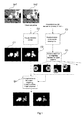
- Figure 1 shows an embodiment of a preferred mode of the invention applied to a video sequence showing one golf ball talking with another golf ball.
- the salience map is determined by a video document from a visual attention model. A salience map is thus obtained as determined in the views C1 and C2 respectively for each picture Im1 and lm2. It is then observed that on the two salience maps C1 and C2 obtained, the salience associated with each ball is very similar. Indeed, the two balls have very similar characteristics, however, the sound associated with these balls are very different. Indeed, the right-hand ball listens whereas the left-hand ball talks. The attention of a person who watches the audio video document naturally focuses on the left-hand ball.
- the salience maps C1 and C2 obtained are therefore not sufficiently representative of the audio video document.
- audio descriptors representative of the audio content of the audio video document are determined. Among these descriptors, descriptors from the audio tracks are determined:
- a weighting function is determined during a step E3.
- This weighting function associates each pixel with a higher or lower weight depending on whether the salience is required to be emphasised or reduced.
- This function therefore has a support having the resolution of the picture as a dimension. By default, namely when no audio data is available, the weighting function is uniform, that is of the value "1" for the entire picture.
- a stereo sound there are two channels, one for each side of the picture.
- the sound is not necessarily overall for a picture but can be more local.
- the left can be distinguished from the right.
- Dolby 5.1 sound the left, right, front, back, etc. can be distinguished.
- Each channel defines a weighting function having a gain dependent on its audio masking capacity. A low amplitude sound with respect to the others cannot be heard so the channel that carries this sound has a low gain.
- the weighting functions are preferentially gaussian of unit amplitude, noted Gauss ⁇ ( ⁇ - represents the spatial extent of the gaussian envelope) having different gains.
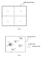
- the centre of application of the weighting functions can be set for each channel by a predetermined grid. An example is given in figure 2 (where there are 6 channels for example as the points are then uniformly distributed on the picture). This figure shows 9 points, the weighting functions have these nine points for their centre.
- the application centre of the weighting functions is preferably located on the salience maxima in each quadrant as shown in figure 3 .
- Salient points are then used having a salience above a predetermined threshold where it is decided to conserve only a predefined number of salient points, or even following the location of the salient points, only one salient point is conserved when a reduced zone of the picture contains a majority of the salient points and that the picture contains several distributed salient zones.
- Laplace type functions can be used, represented by a square window centred on a point with a size, either fixed or variable.
- GainWeight i CSL i p ⁇ + ⁇ j CSL j p
- GainWeight i showing the gain of the channel i and CSLi showing the sound level of the channel i.
- P is an exponent, preferably of the value 2
- ⁇ is a low value constant preventing division by zero. If the channels have the same sound level or a very close sound level, the gain associated with each channel is the same. However, the higher the sound level of a channel in comparison with the sound levels of the other channels, the higher its gain.
- Each channel gain multiplies the gain of a previously defined weighting window, noted as Weight.
- Weight The amplitude of this weighting window depends on the gain of the channel.
- GainWeight ⁇ 2 i GainWeight i * Weight
- a weighting window around this maximum is defined as shown in figure 3 .
- the position of the salience maxima is important for applying this weighting function. Indeed, for a salience maximum located to the right of the picture, it is important to apply to it the GainWeight value of the right-hand channel, and conversely for maxima located to the left of the picture, it is important to apply to it a GainWeight value of the left-hand channel.
- the distance of the salience maxima are calculated with respect to the edges of the picture.
- a high GainWeight coefficient for the maxima located near the right-hand edge of the picture is applied and a low coefficient for the pixels located near the left-hand edge of the picture.
- a high GainWeight coefficient for the maxima located near the left-hand edge of the picture is applied and a low coefficient for the pixels located near the right-hand edge of the picture.
- Figures 4a to 7b show different embodiments of Gainweight2 in the case of a stereo sound, comprising a right-hand channel and a left-hand channel. These embodiments do not change only the salience of the maxima of the visual map as described above but change the salience of all the points of the picture.
- Figure 4a shows a first embodiment for the right-hand channel.
- GainWeight 2 d is maximum for the points located on the right of the picture and becomes equal to 1 for the central point and the points of the picture located to the left of the central point.
- Figure 4b shows a first embodiment for the left-hand channel.
- GainWeight 2 g is maximum for the points located on the left of the picture and becomes equal to 1 for the central point and the points of the picture located to the right of the central point.
- Weight thus represents a linear function.
- This linear function is predefined, the variation being able to depend on the intensity of modulation required by the user.
- the gain of the left-hand channel is greater than the gain of the right-hand channel.
- Figures 5a and 5b show a logarithmic type decrease on the right and on the left.
- Figure 5b shows a second embodiment for the right-hand channel.
- GainWeight 2 d is maximum for the points located on the right of the picture and becomes equal to 1 for the central point and the points of the picture located to the left of the central point. Weight thus represents an increasing exponential function exp(x).
- Figure 5b shows a second embodiment for the left-hand channel.
- GainWeight 2 g is maximum for the points located on the left of the picture and becomes equal to 1 for the central point and the points of the picture located to the right of the central point. Weight thus represents a decreasing exponential function exp(x). This increasing or decreasing exponential function is predefined, the variation being able to depend on the intensity of modulation required by the user.
- Figure 6a shows a third embodiment for the right-hand channel.
- GainWeight 2 d is maximum for the points located on the right of the picture and remain constant for a zone of the picture to the right of the centre, and for example located in the right-hand quarter or the picture. It has the value "1" otherwise.
- Figure 6b shows a third embodiment for the left-hand channel.
- GainWeight 2 d is maximum for the points located on the left of the picture and remain constant for a zone of the picture to the left of the centre, and for example located in the left-hand quarter or the picture. It has the value "1" otherwise. This function is predefined, the variation being able to depend on the intensity of modulation required by the user.
- Figure 7a shows a fourth embodiment for the right-hand channel.
- GainWeight 2 d is maximum for the points located on the right of the picture and decreases linearly up to the left of the picture.
- Figure 7b shows a fourth embodiment for the left-hand channel.
- GainWeight 2 g is maximum for the points located on the left of the picture and decreases linearly up to the right of the picture. The slope of these two last curves is identical.
- the gain of the right-hand channel being greater than the gain of the left-hand channel, the points located on the right of the picture have a greater increase in their salience than the points located to the left of the picture. This function is predefined, the variation being able to depend on the intensity of modulation required by the user.
- the visual salience map is then multiplied by all the N weighting functions.
- the N maps obtained are then averaged to obtain an intermediate map SMMod.
- a step E5 the temporal variations of the sound level are taken into account.
- the sound level changes suddenly, and more particularly when the level goes from a low level to a high level the visual attention increases, is high. Moreover, when passing to silence, the visual attention is certainly less strong.
- TAC modulation coefficient of the salience
- Figure 3 shows an example of change of the TAC coefficient as a function of the overall sound level.
- the temporal attenuation coefficient TAC depends on the temporal variability of the value of the overall sound level OSL, integrated over a few seconds and its amplitude, also temporally averaged. This coefficient is applied uniformly to the salience map. By default, it is 1. In other terms: during a period of silence, the salience is weighted by a coefficient tending toward 0, so as not to give priority to one zone over another.
- SMMod ⁇ 2 CTA ⁇ SMMod
- the invention as described in the different embodiments described previously tends to reduce the salience of the centre of the picture. However, it is sometimes important not to reduce this salience and rather to accentuate it.
- the gains of the different channels are similar (the sound uniformly distributed between the channels), either nothing is done or the centre is accentuated by default.
- the application described above is particularly applied in a context of a dialogue between 2 people. For a more general case, the centre of the picture remains a priority zone of attraction.
Landscapes
- Engineering & Computer Science (AREA)
- Theoretical Computer Science (AREA)
- Computer Vision & Pattern Recognition (AREA)
- General Physics & Mathematics (AREA)
- Physics & Mathematics (AREA)
- Evolutionary Computation (AREA)
- Artificial Intelligence (AREA)
- Data Mining & Analysis (AREA)
- Multimedia (AREA)
- Computing Systems (AREA)
- Bioinformatics & Cheminformatics (AREA)
- Software Systems (AREA)
- Health & Medical Sciences (AREA)
- Medical Informatics (AREA)
- General Health & Medical Sciences (AREA)
- Life Sciences & Earth Sciences (AREA)
- Databases & Information Systems (AREA)
- Bioinformatics & Computational Biology (AREA)
- Evolutionary Biology (AREA)
- General Engineering & Computer Science (AREA)
- Stereophonic System (AREA)
- Information Retrieval, Db Structures And Fs Structures Therefor (AREA)
- Television Signal Processing For Recording (AREA)
- Two-Way Televisions, Distribution Of Moving Picture Or The Like (AREA)
Description
- The invention relates more particularly to the recognition of the audio characteristics for determining the salient of an audio video document.
The determination of the salient zones of an audio video document is useful for different applications such as compression (the salient zones are coded on a greater number of bits for example or the quantization step for said zone is modified), indexing (it is possible to index the documents by using the information in these salient zones), etc.
There are several methods for determining the salience of a video document. The European patentEP1695288 filed in the name of Thomson Licensing on 14 December 2004 describes a particularly effective method for establishing the salience map of a video document.
However, in some cases, the video does not enable the salience of an audio video document to be obtained in sufficiently accurate manner. -
WO 2004/043054 andUS 2004/0088726 discloses methods taking into account audio signal for assessing audio video images. - In addition, the document "Integrating audiovisual information for the control of overt attention" (ONAT, LIBERTUS and KOENING, JOURNAL OF VISION , vol.7, no.10 25 July 2007 (2007-07-25), pages 1-16 XP002491583, ISSN: 1534-7362) mentions the influence of the sound origin direction in the combined audio visual attention.
- To improve the relevance of current methods, the invention proposes to associate audio characteristics with the visual characteristics, by means of the method according to
claim 1. - Preferentially, the weighting function of each channel is a linear function such that the pixels located on the channel side have a greater weighting than the pixels located spatially distant from the channel.
- When the audio is of the stereo type, advantageously, the pixels located to the left of the picture will have a greater weighting for the weighting function of the left-hand channel and a lower weighting for the pixels located to the right of the picture.
- Preferentially, the salience map is weighted by a coefficient dependent on the temporal variation of the sound level.
- The invention also relates to a device according to
claim 5. - The invention will be better understood and illustrated by means of embodiments and implementations, by no means limiting, with reference to the annexed figures, wherein:
-
figure 1 shows an embodiment of the invention and effects of the invention applied to an audio video document, -
figure 2 shows an example of a centre of application of the weighting functions, -
figure 3 represents a preferred embodiment showing, as centre of application, weighting functions, salient point of the video map with their associated weighting window, -
figures 4a and 4b show respectively, for the right-hand and left-hand channel, a first variation example of the weighting functions in the case of stereo, -
figures 5a and 5b show respectively, for the right-hand and left-hand channel, a second variation example of the weighting functions in the case of stereo, -
figures 6a and 6b show respectively, for the right-hand and left-hand channel, a third variation example of the weighting functions in the case of stereo, -
figures 7a and 7b show respectively, for the right-hand and left-hand channel, a fourth variation example of the weighting functions in the case of stereo, -
figure 8 shows the relationship between the overall sound level and the temporal attenuation coefficient. - The modules shown are functional units that may or may not correspond to physically distinguishable units. For example, these modules or some of them can be grouped together in a single component, or constitute functions of the same software. On the contrary, some modules may be composed of separate physical entities.
-
Figure 1 shows an embodiment of a preferred mode of the invention applied to a video sequence showing one golf ball talking with another golf ball.
In step E1, the salience map is determined by a video document from a visual attention model. A salience map is thus obtained as determined in the views C1 and C2 respectively for each picture Im1 and lm2. It is then observed that on the two salience maps C1 and C2 obtained, the salience associated with each ball is very similar. Indeed, the two balls have very similar characteristics, however, the sound associated with these balls are very different. Indeed, the right-hand ball listens whereas the left-hand ball talks. The attention of a person who watches the audio video document naturally focuses on the left-hand ball. The salience maps C1 and C2 obtained are therefore not sufficiently representative of the audio video document.
Hence, during a step E2, audio descriptors representative of the audio content of the audio video document are determined.
Among these descriptors, descriptors from the audio tracks are determined: - The sound level of each channel (CSL) (right (r), left (l), bottom (b), top (t), back right (rl), back left (bl), etc.),
- The overall sound level (OSL) (period of silence, period of activity), that is the overall sum of the sound levels of the CSL channels,
- The acoustic environment (AE),
- The temporal variation of the sound level (SLTV) (passage from silence to strong activity),
- The spatio-temporal variation of the sound level (SLSTV) (passage from left to right, etc.).
- From these audio descriptors, a weighting function is determined during a step E3. This weighting function associates each pixel with a higher or lower weight depending on whether the salience is required to be emphasised or reduced. This function therefore has a support having the resolution of the picture as a dimension. By default, namely when no audio data is available, the weighting function is uniform, that is of the value "1" for the entire picture.
- If a stereo sound is available, there are two channels, one for each side of the picture. When editing the sound on the video, it is therefore possible to give more sound to the right-hand side than the left-hand side if the right-hand side is required to be emphasised, if for example a person who is on the right-hand side of the picture speaks whereas a person on the left-hand side does not speak.
Hence the sound is not necessarily overall for a picture but can be more local. With a stereo sound for example, the left can be distinguished from the right. With Dolby 5.1 sound, the left, right, front, back, etc. can be distinguished. - Each channel defines a weighting function having a gain dependent on its audio masking capacity. A low amplitude sound with respect to the others cannot be heard so the channel that carries this sound has a low gain. The weighting functions are preferentially gaussian of unit amplitude, noted Gaussσ (σ- represents the spatial extent of the gaussian envelope) having different gains.
The centre of application of the weighting functions can be set for each channel by a predetermined grid. An example is given infigure 2 (where there are 6 channels for example as the points are then uniformly distributed on the picture).
This figure shows 9 points, the weighting functions have these nine points for their centre. - The application centre of the weighting functions is preferably located on the salience maxima in each quadrant as shown in
figure 3 . Salient points are then used having a salience above a predetermined threshold where it is decided to conserve only a predefined number of salient points, or even following the location of the salient points, only one salient point is conserved when a reduced zone of the picture contains a majority of the salient points and that the picture contains several distributed salient zones.
In other embodiments, Laplace type functions can be used, represented by a square window centred on a point with a size, either fixed or variable. - The gain of each audio channel is given by the following equation:

- GainWeighti showing the gain of the channel i and CSLi showing the sound level of the channel i.
P is an exponent, preferably of the value 2,
ε is a low value constant preventing division by zero. If the channels have the same sound level or a very close sound level, the gain associated with each channel is the same. However, the higher the sound level of a channel in comparison with the sound levels of the other channels, the higher its gain. - Each channel gain multiplies the gain of a previously defined weighting window, noted as Weight.
The amplitude of this weighting window depends on the gain of the channel.
- Hence, when the application centre of the weighting functions is located on the salience maxima, a weighting window around this maximum is defined as shown in
figure 3 . When in stereo mode, the position of the salience maxima is important for applying this weighting function. Indeed, for a salience maximum located to the right of the picture, it is important to apply to it the GainWeight value of the right-hand channel, and conversely for maxima located to the left of the picture, it is important to apply to it a GainWeight value of the left-hand channel. Hence, the distance of the salience maxima are calculated with respect to the edges of the picture. For the weighting function of the right-hand channel, a high GainWeight coefficient for the maxima located near the right-hand edge of the picture is applied and a low coefficient for the pixels located near the left-hand edge of the picture.
For the weighting function of the left-hand channel, a high GainWeight coefficient for the maxima located near the left-hand edge of the picture is applied and a low coefficient for the pixels located near the right-hand edge of the picture.
When the audio is not stereo but Dolby 5.1, then a distance is not calculated with respect to the edges of the picture but a position in the picture. According to this position, the influence of the channel on this point is determined. - To take distance into account, an additional weighting factor can be added to the previous equation GainWeight2 i = GainWeighti *Weight.
- The equation dependent on the notion of distant thus becomes

α depends on the eccentricity with respect to the centre (xc,yc). Namely, the current point (x,y), alpha(x,y)= (x-xc)2-(y-yc)2. So, if (x,y)=(xc,yc), α tends toward zero, and otherwise alpha increases with the distance with respect to the centre. -
Figures 4a to 7b show different embodiments of Gainweight2 in the case of a stereo sound, comprising a right-hand channel and a left-hand channel. These embodiments do not change only the salience of the maxima of the visual map as described above but change the salience of all the points of the picture.
Figure 4a shows a first embodiment for the right-hand channel. GainWeight2d is maximum for the points located on the right of the picture and becomes equal to 1 for the central point and the points of the picture located to the left of the central point.
Figure 4b shows a first embodiment for the left-hand channel. GainWeight2g is maximum for the points located on the left of the picture and becomes equal to 1 for the central point and the points of the picture located to the right of the central point. Weight thus represents a linear function.
This linear function is predefined, the variation being able to depend on the intensity of modulation required by the user.
Infigures 4a and 4b , it is also noted that the gain of the left-hand channel is greater than the gain of the right-hand channel. Hence, when multiplying by all the weighting functions, a more accentuated salience is obtained for the points to the left than for the points to the right. -
Figures 5a and 5b show a logarithmic type decrease on the right and on the left.
Figure 5b shows a second embodiment for the right-hand channel. GainWeight2d is maximum for the points located on the right of the picture and becomes equal to 1 for the central point and the points of the picture located to the left of the central point. Weight thus represents an increasing exponential function exp(x). -
Figure 5b shows a second embodiment for the left-hand channel. GainWeight2g is maximum for the points located on the left of the picture and becomes equal to 1 for the central point and the points of the picture located to the right of the central point. Weight thus represents a decreasing exponential function exp(x).
This increasing or decreasing exponential function is predefined, the variation being able to depend on the intensity of modulation required by the user. -
Figure 6a shows a third embodiment for the right-hand channel. GainWeight2d is maximum for the points located on the right of the picture and remain constant for a zone of the picture to the right of the centre, and for example located in the right-hand quarter or the picture. It has the value "1" otherwise. -
Figure 6b shows a third embodiment for the left-hand channel. GainWeight2d is maximum for the points located on the left of the picture and remain constant for a zone of the picture to the left of the centre, and for example located in the left-hand quarter or the picture. It has the value "1" otherwise.
This function is predefined, the variation being able to depend on the intensity of modulation required by the user. -
Figure 7a shows a fourth embodiment for the right-hand channel. GainWeight2d is maximum for the points located on the right of the picture and decreases linearly up to the left of the picture.
Figure 7b shows a fourth embodiment for the left-hand channel. GainWeight2g is maximum for the points located on the left of the picture and decreases linearly up to the right of the picture.
The slope of these two last curves is identical. The gain of the right-hand channel being greater than the gain of the left-hand channel, the points located on the right of the picture have a greater increase in their salience than the points located to the left of the picture. This function is predefined, the variation being able to depend on the intensity of modulation required by the user. - During a step E4,
figure 1 , the visual salience map is then multiplied by all the N weighting functions. The N maps obtained are then averaged to obtain an intermediate map SMMod.
Given SM the visual salience map,
Given SMMod the audiovisual salience map,
Given N sound channels,
Given Norm the scale factor,
The audiovisual salience map is then obtained from the following equation:
- During a step E5, the temporal variations of the sound level are taken into account.
When the sound level changes suddenly, and more particularly when the level goes from a low level to a high level, the visual attention increases, is high. Moreover, when passing to silence, the visual attention is certainly less strong. - It is therefore proposed to temporally apply a modulation coefficient of the salience, noted as TAC for temporal attenuation coefficient.
Figure 3 shows an example of change of the TAC coefficient as a function of the overall sound level. - The temporal attenuation coefficient TAC depends on the temporal variability of the value of the overall sound level OSL, integrated over a few seconds and its amplitude, also temporally averaged. This coefficient is applied uniformly to the salience map. By default, it is 1.
In other terms: during a period of silence, the salience is weighted by a coefficient tending toward 0, so as not to give priority to one zone over another.
- It is further noted that the invention as described in the different embodiments described previously tends to reduce the salience of the centre of the picture. However, it is sometimes important not to reduce this salience and rather to accentuate it.
By default, if the gains of the different channels are similar (the sound uniformly distributed between the channels), either nothing is done or the centre is accentuated by default.
The application described above is particularly applied in a context of a dialogue between 2 people. For a more general case, the centre of the picture remains a priority zone of attraction.
Claims (5)
- Method for determining the salience map of an audio video document including a plurality of audio channels characterized in that it comprises the steps of:- calculating (E1) a video salience map in relation to the video part of said document for each image of said video document,- determining (E2), as an audio descriptor representative of the audio content of said audio video document, the sound level of each audio channel,- associating a spatial position in each image for each audio channel,- for each audio channel, calculating (E3)- the gain of said audio channel as a function of the sound level of said audio channel and of the sound level of all the audio channels,- a weighting function which associates for each pixel of the image a weight, which is relative to said audio descriptor for each pixel of the image as a function of its spatial position in the image and the spatial location of said audio channel and of the value of the gain of said audio channel,- for each audio channel, calculating (E4) an audio video salience map by multiplying the video salience map by the weighting function associated with said audio channel,- obtaining a single audio video salience map by averaging the calculated audio video salience maps.
- Method according to claim 1, characterized in that said weighting function of each channel is a linear function such that the pixels located on the channel side have a greater weighting than the pixels located spatially distant from said channel.
- Method according to claim 2, characterized in that when the audio is of the stereo type, the pixels located to the left of the image will have a greater weighting for the weighting function of the left-hand channel and a lower weighting for the pixels located to the right of the image.
- Method according to claim 3, characterized in that the salience map is weighted by a coefficient dependent on the temporal variation of the sound level.
- Device for determining the salience map of an audio video document including a plurality of audio channels characterized in that it comprises:- means for calculating a video salience map in relation to the video part of said document, for each image of said video document,- means for determining, as an audio descriptor representative of the audio content of said audio video document, the sound level of each audio channel- means of associating a spatial position in each image for each audio channel,- for each audio channel, means for calculating (E3)- the gain of said audio channel as a function of the sound level of said audio channel and of the sound level of all the audio channels,- a weighting function which associates for each pixel of the image a weight, which is relative to said audio descriptor for each pixel of the image as a function of its spatial position in the image and the spatial location of said audio channel and of the value of the gain of said audio channel,- means for calculating (E4), for each audio channel, an audio video salience map by multiplying the video salience map by the weighting function associated with said audio channel,- means for obtaining a single audio video salience map by averaging the calculated audio video salience maps.
Applications Claiming Priority (1)
| Application Number | Priority Date | Filing Date | Title |
|---|---|---|---|
| FR0760122 | 2007-12-20 |
Publications (2)
| Publication Number | Publication Date |
|---|---|
| EP2075758A1 EP2075758A1 (en) | 2009-07-01 |
| EP2075758B1 true EP2075758B1 (en) | 2013-04-24 |
Family
ID=39651293
Family Applications (1)
| Application Number | Title | Priority Date | Filing Date |
|---|---|---|---|
| EP08172370.2A Ceased EP2075758B1 (en) | 2007-12-20 | 2008-12-19 | Method and device for calculating the salience map of an audio video document |
Country Status (5)
| Country | Link |
|---|---|
| US (1) | US8374492B2 (en) |
| EP (1) | EP2075758B1 (en) |
| JP (1) | JP5496499B2 (en) |
| CN (1) | CN101470756B (en) |
| TW (1) | TWI455064B (en) |
Families Citing this family (10)
| Publication number | Priority date | Publication date | Assignee | Title |
|---|---|---|---|---|
| US8396282B1 (en) * | 2008-10-31 | 2013-03-12 | Hrl Labortories, Llc | Method and system for computing fused saliency maps from multi-modal sensory inputs |
| US8396249B1 (en) * | 2008-12-23 | 2013-03-12 | Hrl Laboratories, Llc | Robot control based on saliency and invariant spatial representations using hierarchical spatial working memory |
| EP3675029B8 (en) | 2011-04-08 | 2022-05-04 | Dolby Laboratories Licensing Corporation | Local definition of global image transformations |
| KR20140046980A (en) | 2012-10-11 | 2014-04-21 | 한국전자통신연구원 | Apparatus and method for generating audio data, apparatus and method for playing audio data |
| WO2014058275A1 (en) * | 2012-10-11 | 2014-04-17 | 한국전자통신연구원 | Device and method for generating audio data, and device and method for playing audio data |
| US9946795B2 (en) | 2014-01-27 | 2018-04-17 | Fujitsu Limited | User modeling with salience |
| CN103957417B (en) * | 2014-04-21 | 2018-01-12 | 深圳市视晶无线技术有限公司 | The method for video coding and system of a kind of high robust |
| CN104778238B (en) * | 2015-04-03 | 2018-01-05 | 中国农业大学 | The analysis method and device of a kind of saliency |
| KR20220117057A (en) * | 2021-02-16 | 2022-08-23 | 삼성전자주식회사 | Method and apparatus for video quality assessment according to the presence and absence of audio |
| KR102943202B1 (en) | 2023-08-10 | 2026-03-23 | 경희대학교 산학협력단 | Method for localizing sound source using audio-visual spatial information and computing device for executing the same, computer program |
Family Cites Families (11)
| Publication number | Priority date | Publication date | Assignee | Title |
|---|---|---|---|---|
| US6072878A (en) * | 1997-09-24 | 2000-06-06 | Sonic Solutions | Multi-channel surround sound mastering and reproduction techniques that preserve spatial harmonics |
| JP4861593B2 (en) * | 2000-04-19 | 2012-01-25 | エスエヌケー テック インベストメント エル.エル.シー. | Multi-channel surround sound mastering and playback method for preserving 3D spatial harmonics |
| US7274741B2 (en) | 2002-11-01 | 2007-09-25 | Microsoft Corporation | Systems and methods for generating a comprehensive user attention model |
| JP2006505853A (en) * | 2002-11-06 | 2006-02-16 | エージェンシー フォー サイエンス,テクノロジー アンド リサーチ | Method for generating quality-oriented importance map for evaluating image or video quality |
| US7433327B2 (en) * | 2003-10-09 | 2008-10-07 | Hewlett-Packard Development Company, L.P. | Method and system for coordinating communication devices to create an enhanced representation of an ongoing event |
| EP1544792A1 (en) | 2003-12-18 | 2005-06-22 | Thomson Licensing S.A. | Device and method for creating a saliency map of an image |
| JP2006279111A (en) * | 2005-03-25 | 2006-10-12 | Fuji Xerox Co Ltd | Information processor, information processing method and program |
| US7720677B2 (en) * | 2005-11-03 | 2010-05-18 | Coding Technologies Ab | Time warped modified transform coding of audio signals |
| JP2007194928A (en) * | 2006-01-19 | 2007-08-02 | Matsushita Electric Ind Co Ltd | Remote monitoring device and remote monitoring method |
| TWI342718B (en) * | 2006-03-24 | 2011-05-21 | Coding Tech Ab | Decoder and method for deriving headphone down mix signal, receiver, binaural decoder, audio player, receiving method, audio playing method, and computer program |
| EP1936566A1 (en) * | 2006-12-22 | 2008-06-25 | Thomson Licensing | Method for creating the saliency map of an image and system for creating reduced pictures of video frames |
-
2008
- 2008-12-05 TW TW097147218A patent/TWI455064B/en not_active IP Right Cessation
- 2008-12-12 JP JP2008317626A patent/JP5496499B2/en not_active Expired - Fee Related
- 2008-12-19 CN CN200810188512XA patent/CN101470756B/en not_active Expired - Fee Related
- 2008-12-19 EP EP08172370.2A patent/EP2075758B1/en not_active Ceased
-
2009
- 2009-02-04 US US12/316,002 patent/US8374492B2/en not_active Expired - Fee Related
Also Published As
| Publication number | Publication date |
|---|---|
| US8374492B2 (en) | 2013-02-12 |
| EP2075758A1 (en) | 2009-07-01 |
| JP5496499B2 (en) | 2014-05-21 |
| TW200929074A (en) | 2009-07-01 |
| TWI455064B (en) | 2014-10-01 |
| CN101470756B (en) | 2012-12-26 |
| JP2009151785A (en) | 2009-07-09 |
| US20090175595A1 (en) | 2009-07-09 |
| CN101470756A (en) | 2009-07-01 |
Similar Documents
| Publication | Publication Date | Title |
|---|---|---|
| EP2075758A1 (en) | Method and device for calculating the silence of an audio video document | |
| US12335715B2 (en) | Processing object-based audio signals | |
| Barumerli et al. | A Bayesian model for human directional localization of broadband static sound sources | |
| EP1374097B1 (en) | Image processing | |
| US8165416B2 (en) | Automatic gain and exposure control using region of interest detection | |
| EP2936485B1 (en) | Object clustering for rendering object-based audio content based on perceptual criteria | |
| JP4714416B2 (en) | Spatial audio parameter display | |
| US9201958B2 (en) | Video object retrieval system and method | |
| EP3239981B1 (en) | Methods, apparatuses and computer programs relating to modification of a characteristic associated with a separated audio signal | |
| US8126266B2 (en) | Video signal processing method, program for the video signal processing method, recording medium recording the program for the video signal processing method, and video signal processing apparatus | |
| US20160035069A1 (en) | Method and apparatus for correcting image | |
| CN110399848A (en) | Video cover generation method, device and electronic equipment | |
| US20100232685A1 (en) | Image processing apparatus and method, learning apparatus and method, and program | |
| US20100138427A1 (en) | Method of organising content items | |
| KR20080067544A (en) | Image processing method and device | |
| EP3275213B1 (en) | Method and apparatus for driving an array of loudspeakers with drive signals | |
| US20190362475A1 (en) | Method and Computer System of Image Enhancement | |
| KR20090050380A (en) | Audio matrix decoding method and apparatus | |
| CN111144344A (en) | Method, device and equipment for determining age of person and storage medium | |
| CN113313635A (en) | Image processing method, model training method, device and equipment | |
| US20240155289A1 (en) | Context aware soundscape control | |
| KR20190005651A (en) | Apparatus and method for detecting scene change | |
| US20240355348A1 (en) | Detecting environmental noise in user-generated content | |
| Nitanda et al. | Audio signal segmentation and classification using fuzzy c‐means clustering | |
| US20260094436A1 (en) | Audio-visual analytic for object rendering in capture |
Legal Events
| Date | Code | Title | Description |
|---|---|---|---|
| PUAI | Public reference made under article 153(3) epc to a published international application that has entered the european phase |
Free format text: ORIGINAL CODE: 0009012 |
|
| AK | Designated contracting states |
Kind code of ref document: A1 Designated state(s): AT BE BG CH CY CZ DE DK EE ES FI FR GB GR HR HU IE IS IT LI LT LU LV MC MT NL NO PL PT RO SE SI SK TR |
|
| AX | Request for extension of the european patent |
Extension state: AL BA MK RS |
|
| 17P | Request for examination filed |
Effective date: 20091217 |
|
| RAP1 | Party data changed (applicant data changed or rights of an application transferred) |
Owner name: THOMSON LICENSING |
|
| AKX | Designation fees paid |
Designated state(s): DE FR GB |
|
| 17Q | First examination report despatched |
Effective date: 20100215 |
|
| REG | Reference to a national code |
Ref country code: DE Ref legal event code: R079 Ref document number: 602008024030 Country of ref document: DE Free format text: PREVIOUS MAIN CLASS: G06T0005000000 Ipc: G06K0009000000 |
|
| GRAP | Despatch of communication of intention to grant a patent |
Free format text: ORIGINAL CODE: EPIDOSNIGR1 |
|
| RIC1 | Information provided on ipc code assigned before grant |
Ipc: G06F 17/30 20060101ALN20121026BHEP Ipc: G06K 9/00 20060101AFI20121026BHEP Ipc: G11B 27/28 20060101ALI20121026BHEP Ipc: G06K 9/62 20060101ALI20121026BHEP |
|
| GRAS | Grant fee paid |
Free format text: ORIGINAL CODE: EPIDOSNIGR3 |
|
| GRAA | (expected) grant |
Free format text: ORIGINAL CODE: 0009210 |
|
| AK | Designated contracting states |
Kind code of ref document: B1 Designated state(s): DE FR GB |
|
| REG | Reference to a national code |
Ref country code: GB Ref legal event code: FG4D |
|
| REG | Reference to a national code |
Ref country code: DE Ref legal event code: R096 Ref document number: 602008024030 Country of ref document: DE Effective date: 20130620 |
|
| REG | Reference to a national code |
Ref country code: DE Ref legal event code: R084 Ref document number: 602008024030 Country of ref document: DE Effective date: 20130427 |
|
| PLBE | No opposition filed within time limit |
Free format text: ORIGINAL CODE: 0009261 |
|
| STAA | Information on the status of an ep patent application or granted ep patent |
Free format text: STATUS: NO OPPOSITION FILED WITHIN TIME LIMIT |
|
| 26N | No opposition filed |
Effective date: 20140127 |
|
| REG | Reference to a national code |
Ref country code: DE Ref legal event code: R097 Ref document number: 602008024030 Country of ref document: DE Effective date: 20140127 |
|
| GBPC | Gb: european patent ceased through non-payment of renewal fee |
Effective date: 20131219 |
|
| PG25 | Lapsed in a contracting state [announced via postgrant information from national office to epo] |
Ref country code: GB Free format text: LAPSE BECAUSE OF NON-PAYMENT OF DUE FEES Effective date: 20131219 |
|
| REG | Reference to a national code |
Ref country code: FR Ref legal event code: PLFP Year of fee payment: 8 |
|
| REG | Reference to a national code |
Ref country code: FR Ref legal event code: PLFP Year of fee payment: 9 |
|
| REG | Reference to a national code |
Ref country code: DE Ref legal event code: R082 Ref document number: 602008024030 Country of ref document: DE Representative=s name: HOFSTETTER, SCHURACK & PARTNER PATENT- UND REC, DE |
|
| REG | Reference to a national code |
Ref country code: FR Ref legal event code: PLFP Year of fee payment: 10 |
|
| PGFP | Annual fee paid to national office [announced via postgrant information from national office to epo] |
Ref country code: FR Payment date: 20171222 Year of fee payment: 10 |
|
| PGFP | Annual fee paid to national office [announced via postgrant information from national office to epo] |
Ref country code: DE Payment date: 20171218 Year of fee payment: 10 |
|
| REG | Reference to a national code |
Ref country code: DE Ref legal event code: R119 Ref document number: 602008024030 Country of ref document: DE |
|
| PG25 | Lapsed in a contracting state [announced via postgrant information from national office to epo] |
Ref country code: FR Free format text: LAPSE BECAUSE OF NON-PAYMENT OF DUE FEES Effective date: 20181231 Ref country code: DE Free format text: LAPSE BECAUSE OF NON-PAYMENT OF DUE FEES Effective date: 20190702 |