EP2075613A2 - Zoom optical system, optical instrument incorporating the zoom optical system, and method of manufacturing the zoom optical system - Google Patents
Zoom optical system, optical instrument incorporating the zoom optical system, and method of manufacturing the zoom optical system Download PDFInfo
- Publication number
- EP2075613A2 EP2075613A2 EP08172753A EP08172753A EP2075613A2 EP 2075613 A2 EP2075613 A2 EP 2075613A2 EP 08172753 A EP08172753 A EP 08172753A EP 08172753 A EP08172753 A EP 08172753A EP 2075613 A2 EP2075613 A2 EP 2075613A2
- Authority
- EP
- European Patent Office
- Prior art keywords
- lens group
- lens
- optical system
- zoom optical
- focal length
- Prior art date
- Legal status (The legal status is an assumption and is not a legal conclusion. Google has not performed a legal analysis and makes no representation as to the accuracy of the status listed.)
- Granted
Links
- 230000003287 optical effect Effects 0.000 title claims abstract description 176
- 238000004519 manufacturing process Methods 0.000 title claims description 13
- 230000005499 meniscus Effects 0.000 claims description 55
- 230000007423 decrease Effects 0.000 claims description 10
- 238000000034 method Methods 0.000 claims description 2
- 230000004075 alteration Effects 0.000 description 141
- 238000010586 diagram Methods 0.000 description 59
- 230000006641 stabilisation Effects 0.000 description 42
- 238000011105 stabilization Methods 0.000 description 42
- 230000000694 effects Effects 0.000 description 13
- 238000003384 imaging method Methods 0.000 description 12
- 239000011521 glass Substances 0.000 description 8
- 230000009471 action Effects 0.000 description 6
- 230000015556 catabolic process Effects 0.000 description 6
- 238000006731 degradation reaction Methods 0.000 description 6
- 239000011347 resin Substances 0.000 description 6
- 229920005989 resin Polymers 0.000 description 6
- 201000009310 astigmatism Diseases 0.000 description 5
- 230000008859 change Effects 0.000 description 3
- 238000010276 construction Methods 0.000 description 2
- 230000002349 favourable effect Effects 0.000 description 2
- 230000006870 function Effects 0.000 description 2
- 239000004973 liquid crystal related substance Substances 0.000 description 2
- 230000009467 reduction Effects 0.000 description 2
- 230000011514 reflex Effects 0.000 description 2
- 238000000926 separation method Methods 0.000 description 2
- 239000002131 composite material Substances 0.000 description 1
- 239000000470 constituent Substances 0.000 description 1
- 230000000994 depressogenic effect Effects 0.000 description 1
- 230000002542 deteriorative effect Effects 0.000 description 1
- 238000010348 incorporation Methods 0.000 description 1
- 230000007246 mechanism Effects 0.000 description 1
- 239000000203 mixture Substances 0.000 description 1
- 238000000465 moulding Methods 0.000 description 1
- 230000002265 prevention Effects 0.000 description 1
- 238000002834 transmittance Methods 0.000 description 1
Images










Classifications
-
- G—PHYSICS
- G02—OPTICS
- G02B—OPTICAL ELEMENTS, SYSTEMS OR APPARATUS
- G02B15/00—Optical objectives with means for varying the magnification
- G02B15/14—Optical objectives with means for varying the magnification by axial movement of one or more lenses or groups of lenses relative to the image plane for continuously varying the equivalent focal length of the objective
- G02B15/145—Optical objectives with means for varying the magnification by axial movement of one or more lenses or groups of lenses relative to the image plane for continuously varying the equivalent focal length of the objective having five groups only
- G02B15/1451—Optical objectives with means for varying the magnification by axial movement of one or more lenses or groups of lenses relative to the image plane for continuously varying the equivalent focal length of the objective having five groups only the first group being positive
- G02B15/145121—Optical objectives with means for varying the magnification by axial movement of one or more lenses or groups of lenses relative to the image plane for continuously varying the equivalent focal length of the objective having five groups only the first group being positive arranged +-+-+
-
- G—PHYSICS
- G02—OPTICS
- G02B—OPTICAL ELEMENTS, SYSTEMS OR APPARATUS
- G02B27/00—Optical systems or apparatus not provided for by any of the groups G02B1/00 - G02B26/00, G02B30/00
- G02B27/64—Imaging systems using optical elements for stabilisation of the lateral and angular position of the image
- G02B27/646—Imaging systems using optical elements for stabilisation of the lateral and angular position of the image compensating for small deviations, e.g. due to vibration or shake
Definitions
- the present invention relates to a zoom optical system, an optical instrument incorporating the zoom optical system, and a method of manufacturing the zoom optical system.
- zoom optical systems suitable for photographic cameras, digital still cameras, video cameras, and so forth (e.g., cf. Japanese Patent Applications Laid-open No. 8-190051 and Laid-open No. 2005-134870 ).
- the conventional zoom optical systems had the problem that they failed to achieve good optical performance: e.g., they are not corrected well for aberration with image stabilization on.
- the present invention has been accomplished in light of the problem and an object of the present invention is to provide a zoom optical system with good optical performance even with image stabilization on, an optical instrument incorporating the zoom optical system, and a method of manufacturing the zoom optical system.
- a zoom optical system comprises, in the order from an object side: a first lens group having a positive refracting power; a second lens group having a negative refracting power; a third lens group having a positive refracting power; a fourth lens group having a negative refracting power; and a fifth lens group having a positive refracting power, and is configured as follows: the fourth lens group has a cemented lens of a negative lens and a positive lens in the order from the object side; and a condition of the following expression is satisfied: vp > 30.0, where vp is an Abbe number of the positive lens.
- the zoom optical system is preferably configured as follows: the positive lens of the cemented lens has an object-side lens surface of a convex shape on the object side.
- the zoom optical system is preferably configured as follows: at least a part of the fourth lens group is moved in a direction orthogonal to an optical axis.
- the zoom optical system is preferably configured as follows: at least a part of the fourth lens group is moved in a direction orthogonal to an optical axis; and a condition of the following expression is satisfied:
- the zoom optical system is preferably configured as follows: a condition of the following expression is satisfied:
- the zoom optical system is preferably configured as follows: a condition of the following expression is satisfied:
- the zoom optical system is preferably configured as follows: a condition of the following expression is satisfied:
- the zoom optical system is preferably configured as follows: a condition of the following expression is satisfied: 2.0 ⁇ f1/f3 ⁇ 4.7, where f1 is a focal length of the first lens group and f3 is a focal length of the third lens group.
- the zoom optical system is preferably configured as follows:
- the zoom optical system is preferably configured as follows:
- the zoom optical system is preferably configured as follows: the fourth lens group has a cemented lens of a negative lens and a positive lens in the order from the object side.
- the zoom optical system is preferably configured as follows:
- the zoom optical system is preferably configured as follows: a condition of the following expression is satisfied:
- the zoom optical system is preferably configured as follows: a condition of the following expression is satisfied: 0.25 ⁇ Rs/(-f4) ⁇ 0.45, where Rs is a radius of curvature of a cemented surface of the cemented lens and f4 is a focal length of the fourth lens group.
- the zoom optical system is preferably configured as follows: a condition of the following expression is satisfied: 0.07 ⁇ Np-Nn ⁇ 0.20, where Np is a d-line refractive index of the positive lens of the cemented lens and Nn is a d-line refractive index of the negative lens of the cemented lens.
- the zoom optical system is preferably configured as follows: a condition of the following expression is satisfied: 15 ⁇ vn-vp ⁇ 27, where vp is an Abbe number of the positive lens of the cemented lens and vn is an Abbe number of the negative lens of the cemented lens.
- the zoom optical system is preferably configured as follows: the cemented lens is comprised of a cemented lens of a biconcave lens and a positive meniscus lens with a convex surface on the object side in the order from the object side.
- the zoom optical system is preferably configured as follows: at least one surface of a lens in the second lens group is formed in an aspherical shape.
- An optical instrument according to the present invention comprises any one of the above-described zoom optical systems.
- a method of manufacturing a zoom optical system comprises the steps of: arranging a first lens group having a positive refracting power, a second lens group having a negative refracting power, a third lens group having a positive refracting power, a fourth lens group having a negative refracting power, and a fifth lens group having a positive refracting power, in the order from an object side; and moving at least a part of the fourth lens group in a direction orthogonal to the optical axis to make correction for an image surface, wherein a condition of the following expression is satisfied:
- the optical instrument incorporating the zoom optical system, and the zoom method of the zoom optical system are configured as described above, good optical performance is achieved even with image stabilization on.
- Fig. 1 is a sectional view showing a configuration of a zoom optical system according to the first embodiment.
- Fig. 2A is aberration diagrams of various aberrations in the first embodiment in focus at infinity in the wide-angle end state.
- Fig. 2B is a meridional transverse aberration diagram with image stabilization against rotational shake of 0.70° in the first embodiment in the infinity photography state in the wide-angle end state.
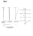
- Fig. 3 is aberration diagrams in the first embodiment in focus at infinity in an intermediate focal length state.
- Fig. 4A is aberration diagrams of various aberrations in the first embodiment in focus at infinity in the telephoto end state.
- Fig. 4B is a meridional transverse aberration diagram with image stabilization against rotational shake of 0.30° in the first embodiment in the infinity photography state in the telephoto end state.
- Fig. 5 is a sectional view showing a configuration of a zoom optical system according to the second embodiment.
- Fig. 6A is aberration diagrams of various aberrations in the second embodiment in focus at infinity in the wide-angle end state.
- Fig. 6B is a meridional transverse aberration diagram with image stabilization against rotational shake of 0.70° in the second embodiment in the infinity photography state in the wide-angle end state.
- Fig. 7 is aberration diagrams in the second embodiment in focus at infinity in an intermediate focal length state.
- Fig. 8A is aberration diagrams of various aberrations in the second embodiment in focus at infinity in the telephoto end state.
- Fig. 8B is a meridional transverse aberration diagram with image stabilization against rotational shake of 0.30° in the second embodiment in the infinity photography state in the telephoto end state.
- Fig. 9 is a sectional view showing a configuration of a zoom optical system according to the third embodiment.
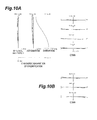
- Fig. 10A is aberration diagram of various aberrations in the third embodiment in focus at infinity in the wide-angle end state.
- Fig. 10B is a meridional transverse aberration diagram with image stabilization against rotational shake of 0.70° in the third embodiment in the infinity photography state in the wide-angle end state.
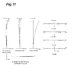
- Fig. 11 is aberration diagrams in the third embodiment in focus at infinity in an intermediate focal length state.
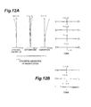
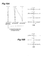
- Fig. 12A is aberration diagrams of various aberrations in the third embodiment in focus at infinity in the telephoto end state.
- Fig. 12B is a meridional transverse aberration diagram with image stabilization against rotational shake of 0.30° in the third embodiment in the infinity photography state in the telephoto end state.
- Fig. 13 is a sectional view showing a configuration of a zoom optical system according to the fourth embodiment.
- Fig. 14A is aberration diagrams of various aberrations in the fourth embodiment in focus at infinity in the wide-angle end state.
- Fig. 14B is a meridional transverse aberration diagram with image stabilization against rotational shake of 0.70° in the fourth embodiment in the infinity photography state in the wide-angle end state.
- Fig. 15 is aberration diagrams in the fourth embodiment in focus at infinity in an intermediate focal length state.
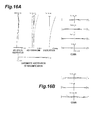
- Fig. 16A is aberration diagrams of various aberrations in the fourth embodiment in focus at infinity in the telephoto end state.
- Fig. 16B is a meridional transverse aberration diagram with image stabilization against rotational shake of 0.30° in the fourth embodiment in the infinity photography state in the telephoto end state.
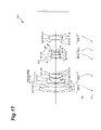
- Fig. 17 is a sectional view showing a configuration of a zoom optical system according to the fifth embodiment.
- Fig. 18A is aberration diagrams of various aberrations in the fifth embodiment in focus at infinity in the wide-angle end state.
- Fig. 18B is a meridional transverse aberration diagram with image stabilization against rotational shake of 0.70° in the fifth embodiment in the infinity photography state in the wide-angle end state.
- Fig. 19 is aberration diagrams in the fifth embodiment in focus at infinity in an intermediate focal length state.
- Fig. 20A is aberration diagrams of various aberrations in the fifth embodiment in focus at infinity in the telephoto end state.
- Fig. 20B is a meridional transverse aberration diagram with image stabilization against rotational shake of 0.30° in the fifth embodiment in the infinity photography state in the telephoto end state.
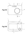
- Fig. 21 A is a front view of a digital still camera equipped with the zoom optical system according to the present invention.
- Fig. 21B is a back view of the digital still camera equipped with the zoom optical system according to the present invention.
- Fig. 22 is a sectional view along line A-A' in Fig. 21A .
- Fig. 23 is a flowchart showing a method of manufacturing the zoom optical system in accordance with the present invention.
- a zoom optical system ZL has a first lens group G1 having a positive refracting power, a second lens group G2 having a negative refracting power, a third lens group G3 having a positive refracting power, a fourth lens group G4 having a negative refracting power, and a fifth lens group having a positive refracting power, in the order from the object side, and, as indicated by arrows in the upper part in Fig. 1 , it is configured to implement image stabilization by moving the fourth lens group G4 in directions orthogonal to the optical axis.
- This zoom optical system ZL shown in Fig. 1 corresponds to the first embodiment described later.
- the fourth lens group G4 has the number of lenses smaller than the other lens groups and is thus easier to reduce the lens diameter, it is more suitable for incorporation of an image stabilization mechanism. This configuration permits the optical system to be corrected well for variation in aberration due to miniaturization of the lens barrel and the image stabilization.
- This zoom optical system ZL is desirably configured so that, upon zooming with change in the lens position state from the wide-angle end state to the telephoto end state, the distance between the first lens group G1 and the second lens group G2 increases, the distance between the second lens group G2 and the third lens group G3 decreases, the distance between the third lens group G3 and the fourth lens group G4 increases, and the distance between the fourth lens group G4 and the fifth lens group G5 decreases.
- This configuration ensures a predetermined zoom ratio while effectively correcting for variation in spherical aberration and curvature of field.
- the zoom optical system ZL is desirably configured so that, upon zooming from the wide-angle end state to the telephoto end state, the first lens group G1, the third lens group G3, and the fifth lens group G5 move in the direction toward the object and a moving distance of the third lens group G3 and a moving distance of the fifth lens group G5 are equal.
- the configuration to move the first lens group G1 to the object side upon zooming from the wide-angle end state to the telephoto end state achieves implementation of reduction in the total length in the wide-angle end state and reduction in the effective diameter of the first lens group G1, and good correction for various aberrations together.
- the zoom function can be served by the lens groups from the third lens group G3 to the fifth lens group G5 and variation in aberration upon zooming can be well corrected for.
- the configuration to equalize the moving distance of the third lens group G3 and the moving distance of the fifth lens group G5 upon zooming permits the third lens group G3 and the fifth lens group G5 to be integrally held.
- This structure suppresses change in mutual decentration of the third lens group G3 and the fifth lens group G5 upon zooming and therefore suppresses occurrence of decentration aberration, thereby achieving good imaging performance.
- the fourth lens group G4 is composed of a cemented lens of a negative lens and a positive lens with an object-side lens surface of a convex shape in the order from the object side and is configured to satisfy condition (1) below: ⁇ p > 30.0 where vp is the Abbe number of the positive lens.
- Condition (1) defines the Abbe number of the positive lens in the fourth lens group G4. When this condition (1) is satisfied, it is feasible to suppress decentration aberration in correction for the image surface with occurrence of camera shake and thus to achieve good imaging performance. If the Abbe number vp is smaller than the lower limit, the fourth lens group G4 will give rise to chromatic aberration so significant as to make correction difficult.
- the fourth lens group G4 is desirably configured to satisfy condition (2) below: 0.20 ⁇ Rs / - f ⁇ 4 ⁇ 0.50 where Rs is a radius of curvature of a cemented surface of the cemented lens and f4 is the focal length of the fourth lens group G4.
- Condition (2) defines the radius of curvature of the cemented surface of the cemented lens to the focal length of the fourth lens group G4. If the ratio is outside the range between the upper limit and the lower limit of condition (2), it will become difficult to correct for spherical aberration and the decentration aberration will be too significant when the fourth lens group G4 is decentered for correction for the image surface with occurrence of camera shake. If the curvature of the cemented surface is too gentle (or if the radius of curvature Rs is too large), it will become difficult to correct for spherical aberration.
- the effect of the present invention can be made more certain by setting the lower limit and the upper limit of condition (2) to 0.25 and 0.40, respectively.
- the fourth lens group G4 is desirably configured to satisfy conditions (3) and (4) below: 0.000 ⁇ Np - Nn ⁇ 0.300 15.0 ⁇ ⁇ n - ⁇ p ⁇ 40.0 where Np is the d-line refractive index of the positive lens in the cemented lens constituting the fourth lens group G4, Nn the d-line refractive index of the negative lens, vn the Abbe number of the negative lens, and vp the Abbe number of the positive lens.
- Condition (3) defines the difference between the refractive indices of the positive lens and the negative lens of the cemented lens constituting the fourth lens group G4. If the difference is outside the range between the upper limit and the lower limit of this condition (3), a tilt of the image surface will become too large to correct for when the fourth lens group G4 is decentered for correction for the image surface with occurrence of camera shake.
- the effect of the present invention can be made more certain by setting the lower limit and the upper limit of condition (3) to 0.005 and 0.200, respectively.
- Condition (4) defines the difference between the Abbe numbers of the positive lens and the negative lens of the cemented lens constituting the fourth lens group G4. If the difference is outside the range between the upper limit and the lower limit of this condition (4), the fourth lens group G4 will give rise to chromatic aberration so significant as to make correction difficult.
- the effect of the present invention can be made more certain by setting the lower limit and the upper limit of condition (4) to 20.0 and 30.0, respectively.
- the zoom optical system ZL is desirably configured to satisfy condition (5) below: 1.0 ⁇ f ⁇ 5 / - f ⁇ 4 ⁇ 2.0 where f4 is the focal length of the fourth lens group G4 and f5 the focal length of the fifth lens group G5.
- Condition (5) defines the focal length of the fifth lens group G5 to the focal length of the fourth lens group G4.
- the zoom optical system ZL satisfies this condition (5), it becomes feasible to ensure the optical performance with image stabilization on and to relieve degradation of optical performance due to manufacturing error.
- the ratio is smaller than the lower limit of condition (5), the refracting power of the fifth lens group G5 will become too strong to correct for comatic aberration. Furthermore, it is unfavorable because it will result in significant degradation of imaging performance against manufacturing error such as decentration among the lens groups, or significant worsening of decentration comatic aberration.
- the ratio is larger than the upper limit of condition (5), the refracting power of the fourth lens group G4 will become too strong. This is unfavorable because spherical aberration and comatic aberration will worsen at the telephoto end.
- the effect of the present invention can be made more certain by setting the upper limit of condition (5) to 1.5.
- the zoom optical system ZL is desirably configured to satisfy condition (6) below: 3.0 ⁇ f ⁇ 1 / - f ⁇ 2 ⁇ 6.9 where f1 is the focal length of the first lens group G1 and f2 the focal length of the second lens group G2.
- Condition (6) defines the focal length of the first lens group G1 to the focal length of the second lens group G2.
- This zoom optical system ZL is able to ensure a sufficient zoom ratio and to implement good optical performance when satisfying the condition (6). If the ratio is smaller than the lower limit of this condition (6), the refracting power of the first lens group G1 will become so strong as to significantly worsen spherical aberration at the telephoto end. It is also unfavorable in that chromatic aberration of magnification will also worsen significantly at the wide-angle end.
- the refracting power of the second lens group G2 will become too strong to correct for off-axis aberrations at the wide-angle end, particularly, curvature of field and astigmatism.
- the effect of the present invention can be made more certain by setting the lower limit and the upper limit of condition (6) to 4.0 and 6.5, respectively.
- the zoom optical system ZL is desirably configured to satisfy condition (7) below: 2.0 ⁇ f ⁇ 1 / f ⁇ 3 ⁇ 4.7 where f1 is the focal length of the first lens group G1 and f3 the focal length of the third lens group G3.
- Condition (7) defines the focal length of the first lens group G 1 to the focal length of the third lens group G3.
- This zoom optical system ZL is able to implement good optical performance and more effective color correction when satisfying the condition (7). If the ratio is larger than the upper limit of condition (7), the refracting power of the third lens group G3 will become too strong to correct for comatic aberration at the wide-angle end and spherical aberration at the telephoto end. It will also result in significant degradation of imaging performance due to manufacturing error. On the other hand, if the ratio is smaller than the lower limit of condition (7), the refracting power of the first lens group G1 will become so strong as to significantly worsen spherical aberration at the telephoto end.
- the effect of the present invention can be made more certain by setting the lower limit and the upper limit of condition (7) to 3.0 and 4.5, respectively.
- the zoom optical system ZL is desirably configured to satisfy condition (8) below: 0.4 ⁇ - f ⁇ 2 / f ⁇ 3 ⁇ 0.9 where f2 is the focal length of the second lens group G2 and f3 the focal length of the third lens group G3.
- Condition (8) defines the focal length of the second lens group G2 to the focal length of the third lens group G3.
- This zoom optical system ZL when satisfying the condition (8), is able to achieve downsizing thereof while ensuring a predetermined back focus. If the ratio is lower than the lower limit of condition (8), the refracting power of the second lens group G2 will become so strong as to worsen curvature of field and astigmatism at the wide-angle end though it is advantageous for securing the back focus. On the other hand, if the ratio is larger than the upper limit of condition (8), the refracting power of the second lens group G2 will become so weak as to increase the moving distance of the second lens group G2 upon zooming and make it difficult to achieve downsizing of the zoom optical system ZL.
- the effect of the present invention can be made more certain by setting the upper limit and the lower limit of condition (8) to 0.8 and 0.5, respectively.
- the first lens group G1 is preferably configured to have a negative lens and two positive lenses. This configuration allows effective correction for spherical aberration.
- the negative lens and one positive lens are preferably constructed as a cemented lens. This permits effective correction for chromatic aberration.
- the second lens group G2 is preferably configured to have three negative lenses and one positive lens. This configuration allows effective correction for various aberrations.
- the second lens group G2 preferably has an aspherical surface and, particularly, it is more preferably configured so that the surface nearest to the object is of an aspherical shape. This permits good correction for curvature of field and distortion at the wide-angle end.
- the two back lenses (positive lens and negative lens nearest to the image surface in the second lens group G2) may be constructed as a cemented lens.
- the third lens group G3 is preferably configured to have a negative lens and two positive lenses. This allows effective correction for spherical aberration.
- the positive lens is preferably constructed in the form of a cemented lens.
- the fourth lens group G4 is preferably configured without any aspheric lens surface.
- the fifth lens group G5 is preferably configured to have a positive single lens and a cemented lens of positive and negative lenses.
- the zoom optical system ZL is configured to make correction for the image surface with occurrence of camera shake by moving the fourth lens group G4 in directions orthogonal to the optical axis as indicated by arrows in the upper part in Fig. 1 .
- the zoom optical system ZL is desirably configured to satisfy condition (9) below: 1.0 ⁇ f ⁇ 4 / f ⁇ 2 ⁇ 3.3 where f2 is the focal length of the second lens group G2 and f4 the focal length of the fourth lens group G4.
- Condition (9) defines the focal length of the fourth lens group G4 to the focal length of the second lens group G2.
- This zoom optical system ZL when satisfying this condition (9), is able to realize good optical performance even with image stabilization on and ensure a predetermined zoom ratio. If the ratio is larger than the upper limit of condition (9), the refracting power of the fourth lens group G4 will become weak. This increases a shift amount of the fourth lens group G4 necessary for the image stabilization and it becomes difficult to simultaneously correct for variation in curvature of field at the wide-angle end and decentration comatic aberration at the telephoto end with image stabilization on.
- the refracting power of the second lens group G2 will become too weak to ensure a predetermined zoom ratio. If the refracting power of the third lens group G3 is increased in order to compensate for it, it will become difficult to correct for spherical aberration at the telephoto end, unfavorably.
- the effect of the present invention can be made more certain by setting the lower limit and the upper limit of condition (9) to 2.0 and3. 0, respectively.
- the zoom optical system ZL is desirably configured to satisfy condition (10) below: 1.0 ⁇ f ⁇ 5 / - f ⁇ 4 ⁇ 2.0 where f4 is the focal length of the fourth lens group G4 and f5 the focal length of the fifth lens group G5.
- Condition (10) defines the focal length of the fifth lens group G5 to the focal length of the fourth lens group G4.
- This zoom optical system ZL when satisfying this condition (10), is able to ensure optical performance with image stabilization on and relieve degradation of optical performance due to manufacturing error. If the ratio is smaller than the lower limit of condition (10), the refracting power of the fifth lens group G5 will become too strong to correct for comatic aberration. Furthermore, it is unfavorable in that it will result in significant degradation of imaging performance against manufacturing error such as decentration among the lens groups, or significant worsening of decentration comatic aberration. On the other hand, if the ratio is larger than the upper limit of condition (10), the refracting power of the fourth lens group G4 will become too strong. This is unfavorable because spherical aberration and comatic aberration will worsen at the telephoto end.
- the effect of the present invention can be made more certain by setting the upper limit of condition (10) to 1.5.
- the zoom optical system ZL is desirably configured to satisfy condition (11) below: 0.4 ⁇ - f ⁇ 2 / f ⁇ 3 ⁇ 0.9 where f2 is the focal length of the second lens group G2 and f3 the focal length of the third lens group G3.
- Condition (11) defines the focal length of the second lens group G2 to the focal length of the third lens group G3.
- This zoom optical system ZL when satisfying condition (11), is able to achieve downsizing thereof while ensuring a predetermined back focus. If the ratio is lower than the lower limit of condition (11), the refracting power of the second lens group G2 will become so strong as to worsen curvature of field and astigmatism at the wide-angle end though it is advantageous for securing the back focus. On the other hand, if the ratio is larger than the upper limit of condition (11), the refracting power of the second lens group G2 will become so weak as to increase the moving distance of the second lens group G2 upon zooming and make it difficult to achieve downsizing of the zoom optical system ZL.
- the effect of the present invention can be made more certain by setting the upper limit and the lower limit of condition (11) to 0.8 and 0.5, respectively.
- the zoom optical system ZL is desirably configured to satisfy condition (12) below: 3.0 ⁇ f ⁇ 1 / - f ⁇ 2 ⁇ 6.9 where f1 is the focal length of the first lens group G1 and f2 the focal length of the second lens group G2.
- Condition (12) defines the focal length of the first lens group G1 to the focal length of the second lens group G2.
- This zoom optical system ZL is able to ensure a sufficient zoom ratio and to implement good optical performance when satisfying the condition (12). If the ratio is smaller than the lower limit of condition (12), the refracting power of the first lens group G1 will become so strong as to significantly worsen spherical aberration at the telephoto end. It is also unfavorable in that chromatic aberration of magnification will also worsen significantly at the wide-angle end.
- the refracting power of the second lens group G2 will become too strong to correct for off-axis aberrations at the wide-angle end, particularly, curvature of field and astigmatism.
- the effect of the present invention can be made more certain by setting the upper limit and the lower limit of condition (12) to 6.5 and 4.0, respectively.
- the zoom optical system ZL is desirably configured to satisfy condition (13) below: 2.0 ⁇ f ⁇ 1 / f ⁇ 3 ⁇ 4.7 where f1 is the focal length of the first lens group G1 and f3 the focal length of the third lens group G3.
- Condition (13) defines the focal length of the first lens group G1 to the focal length of the third lens group G3.
- This zoom optical system ZL is able to implement good optical performance and more effective color correction when satisfying the condition (13). If the ratio is larger than the upper limit of condition (13), the refracting power of the third lens group G3 will become too strong to correct for comatic aberration at the wide-angle end and spherical aberration at the telephoto end. It will also result in significant degradation of imaging performance due to manufacturing error. On the other hand, if the ratio is smaller than the lower limit of condition (13), the refracting power of the first lens group G1 will become so strong as to significantly worsen spherical aberration at the telephoto end.
- the effect of the present invention can be made more certain by setting the lower limit and the upper limit of condition (13) to 3.0 and 4.5, respectively.
- this zoom optical system ZL is configured to make correction for the image surface with occurrence of camera shake by moving the fourth lens group G4 in the directions orthogonal to the optical axis, and when this fourth lens group G4 is composed of a cemented lens of a biconcave negative lens and a positive meniscus lens with a convex surface on the object side in the order from the object side and further configured to satisfy conditions (14)-(16) below, it becomes feasible to suppress decentration aberration in correction for the image surface with occurrence of camera shake and achieve good imaging performance.
- condition (14) preferably satisfies condition (14) below: 0.25 ⁇ Rs / - f ⁇ 4 ⁇ 0.45 where f4 is the focal length of the fourth lens group G4 and Rs the radius of curvature of a cemented surface of the cemented lens.
- Condition (14) defines the radius of curvature of the cemented surface of the cemented lens to the focal length of the fourth lens group G4. If the ratio is smaller than the lower limit of condition (14), the curvature of the cemented surface will become so small as to make negative spherical aberration too significant to correct for. On the other hand, if the ratio is larger than the upper limit of condition (14), the curvature of the cemented surface will become so large as to make positive spherical aberration too significant to correct for. If the ratio is outside the range between the upper limit and the lower limit, it will be difficult to correct for spherical aberration and the decentration aberration will be so significant when the fourth lens group G4 is decentered for correction for the image surface with occurrence of camera shake.
- the effect of the present invention can be made more certain by setting the upper limit and the lower limit of condition (14) to 0.40 and 0.30, respectively.
- the fourth lens group G4 is desirably configured to satisfy condition (15) below: 0.07 ⁇ Np - Nn ⁇ 0.20 where Np is the d-line refractive index of the positive meniscus lens in the cemented lens constituting the fourth lens group G4, and Nn the d-line refractive index of the biconcave lens.
- Condition (15) defines the difference between the refractive indices of the positive meniscus lens and the biconcave lens of the cemented lens constituting the fourth lens group G4. If the difference is outside the range between the upper limit and the lower limit of this condition (15), a tilt of the image surface will become too large to correct for when the fourth lens group G4 is decentered for correction for the image surface with occurrence of camera shake.
- the fourth lens group G4 is desirably configured to satisfy condition (16) below: 15 ⁇ ⁇ n - ⁇ p ⁇ 27 where vp is the Abbe number of the positive meniscus lens in the cemented lens constituting the fourth lens group G4, and vn the Abbe number of the biconcave lens.
- Condition (16) defines the difference between the Abbe numbers of the positive meniscus lens and the biconcave lens of the cemented lens constituting the fourth lens group G4. If the difference is outside the range between the upper limit and the lower limit of this condition (16), the fourth lens group G4 will give rise to chromatic aberration too significant to correct for.
- This zoom optical system ZL is desirably configured so that the second lens group G2 has an aspherical surface. This permits good correction for curvature of field and distortion at the wide-angle end.
- Figs. 21 and 22 show a configuration of a digital still camera 1 (which will be referred to simply as a camera) as an optical instrument equipped with the above-described zoom optical system ZL.
- This camera is configured as follows: when an unrepresented power button is depressed, an unrepresented shutter of a taking lens (zoom optical system ZL) is opened, and light from an unrepresented object is condensed in the zoom optical system ZL to be focused on an image sensor C (e.g., CCD, CMOS, or the like) arranged on the image plane.
- the object image focused on the image sensor C is displayed on a liquid crystal monitor 2 located on the back of the camera 1.
- a photographer determines a composition of the object image while watching the liquid crystal monitor 2.
- the photographer pushes a release button 3 to take the object image by the image sensor C and record to save it in an unrepresented memory.
- This camera 1 is provided with an auxiliary light emitter 4 to emit auxiliary light to a dark object, a wide(W)-tele(T) button 5 for zooming of the zoom optical system ZL from the wide-angle end state (W) to the telephoto end state (T), a function button 6 used for setting various conditions of the camera 1, and so forth.
- the camera 1 may be constructed as a so-called single-lens reflex camera having a quick return mirror, a focusing screen, a pentagonal prism, an eyepiece, and so forth.
- the zoom optical system ZL may be one incorporated in an interchangeable lens to be detachably mounted on the single-lens reflex camera.
- the lens system in the embodiments of the present invention is composed of five movable groups, but it is also possible to add another lens group between the lens groups, or to add another lens group adjacent to the image side or the object side of the lens system.
- the lens groups refers to parts, separated from each other by an air space which varies at the time of varying power, each having at least one lens.
- a single lens group or two or more lens groups, or a partial lens group may be configured as a focusing lens group to be moved in the direction of the optical axis so as to implement focusing from an infinity object to a near object.
- the focusing lens group is also applicable to autofocus, and is also suitable for drive of a motor (e.g., an ultrasonic motor) for autofocus.
- a motor e.g., an ultrasonic motor
- the second lens group G2 be configured as the focusing lens group.
- the first lens group G1 is configured as the focusing lens group.
- the lens system in order to prevent a failure in photography due to blurring of the image caused by camera shake or the like likely to occur in a zoom lens with a high zoom ratio, the lens system is combined with a vibration detector for detecting vibration of the lens system, and a driving device; the whole or a part of one lens group out of the lens groups forming the lens system is decentered as an anti-vibration lens group; the driving device drives the anti-vibration lens group so as to correct the image blur (variation in position of the image plane) caused by vibration of the lens system detected by the vibration detector; the image is shifted thereby to correct the image blur.
- the fourth lens group G4 be configured as the anti-vibration lens group.
- the zoom optical system ZL according to the embodiments of the present invention can be functioned as a so-called anti-vibration optical system.
- the aspherical surface may be any one of an aspherical surface made by grinding, a glass mold aspherical surface made by molding glass into an aspherical shape, and a composite aspherical surface made by forming an aspherical shape of resin on a surface of glass.
- the lens surfaces may also be diffractive surfaces.
- the lenses may be gradient-index lenses (GRIN lenses) or plastic lenses.
- the lens surfaces also may be formed spherical or planar.
- the spherical or planar lens surfaces are favorable in that processing of lenses and adjustment of their assembling are easy, so as to prevent optical performances from deteriorating because of errors in the processing and adjustment of assembling. They are also favorable in that depicting performances deteriorate less even when the image surface is shifted.
- An aperture stop S is preferably arranged near the third lens group G3, but it is also possible to use a lens frame so as to serve as an aperture stop instead thereof, without providing any member as an aperture stop.
- This aperture stop is conceivably positioned before, inside, or after the third lens group G3.
- each lens surface may be coated with an antireflection film having high transmittance in a wide wavelength region, to reduce flares and ghosts, thereby achieving high optical performance.
- the first lens group G1, second lens group G2, third lens group G3, fourth lens group G4, and fifth lens group G5 of this embodiment are built into a cylindrical lens barrel.
- the lens groups may be built into the lens barrel one by one in their order along the optical axis, or a part or all of the lens groups may be integrally held with a holding member and then assembled with a lens barrel member.
- the lens groups are built into the lens barrel, whether or not an image of an object is formed in the state where the lens groups are built into the lens barrel is determined.
- the zoom optical system After the zoom optical system is assembled as mentioned above, its various actions are verified.
- the actions include a varying power action in which at least a part of lens groups moves along the optical axis when varying power, a focusing action in which a lens group for focusing from an object at infinity to an object at a close distance moves along the optical axis, and a camera shake correcting action in which at least a part of lenses moves so as to have a component orthogonal to the optical axis.
- the zoom optical system ZL is desirably configured so that the distance between the first lens group G1 and the second lens group G2 increases, the distance between the second lens group G2 and the third lens group G3 decreases, the distance between the third lens group G3 and the fourth lens group G4 increases, and the distance between the fourth lens group G4 and the fifth lens group G5 decreases.
- the various actions can be verified in any order.
- Fig. 1 is a sectional view showing the configuration of the zoom optical system ZL according to an example of the present invention, and the refracting power layout of this zoom optical system ZL and movement of each of lens groups during change in the focal length state from the wide-angle end state (W) to the telephoto end state (T), namely upon zooming from the wide-angle end state (W) to the telephoto end state (T), are indicated in the lower part by arrows in Fig. 1 .
- Fig. 1 is a sectional view showing the configuration of the zoom optical system ZL according to an example of the present invention, and the refracting power layout of this zoom optical system ZL and movement of each of lens groups during change in the focal length state from the wide-angle end state (W) to the telephoto end state (T), namely upon zooming from the wide-angle end state (W) to the telephoto end state (T), are indicated in the lower part by arrows in Fig. 1 .
- Fig. 1 is a sectional view
- the zoom optical system ZL of the example is composed of the first lens group G1 having a positive refracting power, the second lens group G2 having a negative refracting power, the third lens group G3 having a positive refracting power, the fourth lens group G4 having a negative refracting power, and the fifth lens group G5 having a positive refracting power in the order from the object side.
- the distances between the lens groups vary so as to increase the aerial gap between the first lens group G1 and the second lens group G2, decrease the aerial gap between the second lens group G2 and the third lens group G3, increase the aerial gap between the third lens group G3 and the fourth lens group G4, and decrease the aerial gap between the fourth lens group G4 and the fifth lens group G5.
- the fourth lens group G4 is moved in the directions orthogonal to the optical axis to implement image stabilization (prevention of vibration).
- the second-order aspheric coefficient A2 is 0.
- the aspherical surface is accompanied by mark * on the left of a surface number.
- Fig. 1 is a drawing showing the configuration of the zoom optical system ZL1 according to the first example of the present invention.
- the first lens group G1 is composed of a cemented lens of a negative meniscus lens L11 with a convex surface on the object side and a biconvex positive lens L12, and a positive meniscus lens L13 with a convex surface on the object side in the order from the object side.
- the second lens group G2 is composed of a negative meniscus lens L21 with a convex surface on the object side, a biconcave negative lens L22, a biconvex positive lens L23, and a negative meniscus lens L24 with a concave surface on the object side in the order from the object side, and the negative meniscus lens L21 located nearest to the object in the second lens group G2 is an aspherical lens with aspherical surface made by laying a resin layer on a glass lens surface on the object side.
- the third lens group G3 is composed of a cemented lens of a negative meniscus lens L31 with a convex surface on the object side and a biconvex positive lens L32, and a cemented lens of a biconvex positive lens L33 and a biconcave negative lens L34 in the order from the object side.
- the fourth lens group G4 is composed of a cemented lens of a biconcave negative lens L41 and a positive meniscus lens L42 with a convex surface on the object side in the order from the object side.
- the fifth lens group G5 is composed of a negative meniscus lens L51 with a concave surface on the object side, and a cemented lens of a biconvex positive lens L52 and a negative meniscus lens L53 with a concave surface on the object side in the order from the object side.
- the stop S is located between the second lens group G2 and the third lens group G3 and moves together with the third lens group G3 upon zooming from the wide-angle end state to the telephoto end state. Focusing from a long distance to a short distance is implemented by moving the second lens group G2 in the direction toward the object.
- the moving lens group for image stabilization is moved by (f-tan ⁇ )/K in the direction orthogonal to the optical axis.
- the anti-vibration factor is 1.19 and the focal length is 18.4 (mm); therefore, the moving distance of the fourth lens group G4 for correction for rotational shake of 0.70° is 0.19 (mm).
- the anti-vibration factor is 1.78 and the focal length is 102.0 (mm); therefore, the moving distance of the fourth lens group G4 for correction for rotational shake of 0.30° is 0.30 (mm).
- Table 1 below presents values of specifications in the first example.
- f represents the focal length
- FNO the F number
- ⁇ a half angle of view
- Bf the back focus.
- the surface number shows an order of each lens surface from the object side along the traveling direction of rays
- the surface separation does a spacing on the optical axis from each optical surface to a next optical surface
- the units of the focal length f, radius of curvature, surface separation, and other lengths presented in all the specification values below are generally "mm," but the units do not always have to be limited to it because equivalent optical performance is achieved when the optical system is proportionally enlarged or reduced.
- the radius of curvature of 0.0000 indicates a plane and the refractive index of air, 1.00000, is omitted.
- W, IFL, T, IH, and TLL denote the Wide-angle end, Intermediate focal length, Telephoto end, Image height, and Total lens length, respectively.
- s, r, d, v. and n denote the Surface No., Radius of curvature, Surface distance, Abbe number, and Refractive index, respectively, in the following tables.
- the lens surface of the sixth surface is formed in an aspherical shape.
- Table 2 below shows the data of the aspherical surface, i.e., values of the radius R of curvature at the top, the conic constant ⁇ , and the aspheric constants A4-A14.
- the following distances vary upon zooming: axial aerial gap d1 between the first lens group G1 and the second lens group G2; axial aerial gap d2 between the second lens group G2 and the third lens group G3; axial aerial gap d3 between the third lens group G3 and the fourth lens group G4; and axial aerial gap d4 between the fourth lens group G4 and the fifth lens group G5.
- Table 3 shows the variable gaps at respective focal lengths in the wide-angle end state, in an intermediate focal length state, and in the telephoto end state.
- f1 represents the focal length of the first lens group G1, f2 the focal length of the second lens group G2, f3 the focal length of the third lens group G3, f4 the focal length of the fourth lens group G4, f5 the focal length of the fifth lens group G5, Rs the radius of curvature of the cemented surface of the cemented lens in the fourth lens group G4, Np the refractive index of the positive meniscus lens L42 for the d-line, Nn the refractive index of the biconcave negative lens L41 for the d-line, vn the Abbe number of the positive meniscus lens L42, and vn the Abbe number of the biconcave negative lens L41.
- Np the refractive index of the positive meniscus lens L42 for the d-line
- Nn the refractive index of the biconcave negative lens L41 for the d-line
- vn the Abbe number of the positive meniscus lens L42
- vn Abbe number of the biconcave negative lens L41
- Fig. 2A shows aberration diagrams of aberrations in the first example in focus at infinity in the wide-angle end state
- Fig. 3 aberration diagrams of aberrations in the first example in focus at infinity in the intermediate focal length state
- Fig. 4A aberration diagrams of aberrations in the first example in focus at infinity in the telephoto end state
- Fig. 2B shows a meridional transverse aberration diagram with image stabilization for the rotational shake of 0.70° in the first example in the infinity photography state in the wide-angle end state
- Fig. 4B a meridional transverse aberration diagram with image stabilization for the rotational shake of 0.30° in the first example in the infinity photography state in the telephoto end state.
- each solid line indicates a sagittal image surface and each dashed line a meridional image surface. Furthermore, in each aberration diagram showing spherical aberration, each solid line indicates spherical aberration, and a dashed line the sine condition.
- the same definition of aberration diagrams also applies to the examples hereinafter. It is clearly seen from the aberration diagrams that in the first example the zoom optical system ZL1 is corrected well for the various aberrations in each of the focal length states from the wide-angle end state to the telephoto end state and thus has excellent imaging performance.
- Fig. 5 is a drawing showing the configuration of the zoom optical system ZL2 according to the second example of the present invention.
- the first lens group G1 is composed of a cemented lens of a negative meniscus lens L11 with a convex surface on the object side and a biconvex positive lens L12, and a positive meniscus lens L 13 with a convex surface on the object side in the order from the object side.
- the second lens group G2 is composed of a negative meniscus lens L21 with a convex surface on the object side, a biconcave negative lens L22, a biconvex positive lens L23, and a biconcave negative lens L24 in the order from the object side, and the negative meniscus lens L21 located nearest to the object in the second lens group G2 is an aspherical lens with an aspherical surface made by laying a resin layer on a glass lens surface on the object side.
- the third lens group G3 is composed of a cemented lens of a negative meniscus lens L31 with a convex surface on the object side and a biconvex positive lens L32, and a positive meniscus lens L33 with a convex surface on the object side in the order from the object side.
- the fourth lens group G4 is composed of a cemented lens of a biconcave negative lens L41 and a positive meniscus lens L42 with a convex surface on the object side in the order from the object side.
- the fifth lens group G5 is composed of a negative meniscus lens L51 with a concave surface on the object side, and a cemented lens of a biconvex positive lens L52 and a negative meniscus lens L53 with a concave surface on the object side in the order from the object side.
- the stop S is located between the second lens group G2 and the third lens group G3 and moves together with the third lens group G3 upon zooming from the wide-angle end state to the telephoto end state. Focusing from a long distance to a short distance is implemented by moving the second lens group G2 in the direction toward the object.
- the moving lens group for image stabilization is moved by (f ⁇ tan ⁇ )/K in the direction orthogonal to the optical axis.
- the anti-vibration factor is 1.22 and the focal length is 18.4 (mm); therefore, the moving distance of the fourth lens group G4 for correction for rotational shake of 0.70° is 0.18 (mm).
- the anti-vibration factor is 1.80 and the focal length is 102.0 (mm); therefore, the moving distance of the fourth lens group G4 for correction for rotational shake of 0.30° is 0.30 (mm).
- Table 5 below presents values of specifications in the second example.
- the lens surface of the sixth surface is formed in an aspherical shape.
- Table 6 shows the data of the aspherical surface, i.e., values of the radius R of curvature at the top, the conic constant ⁇ , and the aspheric constants A4-A14.
- the following distances vary upon zooming: axial aerial gap d1 between the first lens group G1 and the second lens group G2; axial aerial gap d2 between the second lens group G2 and the third lens group G3; axial aerial gap d3 between the third lens group G3 and the fourth lens group G4; and axial aerial gap d4 between the fourth lens group G4 and the fifth lens group G5.
- Table 7 below shows the variable gaps at respective focal lengths in the wide-angle end state, in an intermediate focal length state, and in the telephoto end state.
- Table 8 presents values corresponding to the respective conditions in the second example.
- Fig. 6A shows aberration diagrams of aberrations in the second example in focus at infinity in the wide-angle end state
- Fig. 7 aberration diagrams of aberrations in the second example in focus at infinity in the intermediate focal length state
- Fig. 8A aberration diagrams of aberrations in the second example in focus at infinity in the telephoto end state
- Fig. 6B shows a meridional transverse aberration diagram with image stabilization for the rotational shake of 0.70° in the second example in the infinity photography state in the wide-angle end state
- Fig. 8B a meridional transverse aberration diagram with image stabilization for the rotational shake of 0.30° in the second example in the infinity photography state in the telephoto end state.
- Fig. 9 is a drawing showing the configuration of the zoom optical system ZL3 according to the third example of the present invention.
- the first lens group G1 is composed of a cemented lens of a negative meniscus lens L1 with a convex surface on the object side and a biconvex positive lens L12, and a positive meniscus lens L 13 with a convex surface on the object side in the order from the object side.
- the second lens group G2 is composed of a negative meniscus lens L21 with a convex surface on the object side, a biconcave negative lens L22, a biconvex positive lens L23, and a negative meniscus lens L24 with a concave surface on the object side in the order from the object side, and the negative meniscus lens L21 located nearest to the object in the second lens group G2 is an aspherical lens with an aspherical surface made by laying a resin layer on a glass lens surface on the object side.
- the third lens group G3 is composed of a cemented lens of a negative meniscus lens L31 with a convex surface on the object side and a biconvex positive lens L32, and a cemented lens of a biconvex positive lens L33 and a negative meniscus lens L34 with a concave surface on the object side in the order from the object side.
- the fourth lens group G4 is composed of a cemented lens of a biconcave negative lens L41 and a positive meniscus lens L42 with a convex surface on the object side in the order from the object side.
- the fifth lens group G5 is composed of a negative meniscus lens L51 with a concave surface on the object side, a biconvex positive lens L52, and a cemented lens of a biconvex positive lens L53 and a negative meniscus lens L54 with a concave surface on the object side in the order from the object side.
- the stop S is located between the second lens group G2 and the third lens group G3 and moves together with the third lens group G3 upon zooming from the wide-angle end state to the telephoto end state. Focusing from a long distance to a short distance is implemented by moving the second lens group G2 in the direction toward the object.
- the moving lens group for image stabilization is moved by (f ⁇ tan ⁇ )/K in the direction orthogonal to the optical axis.
- the anti-vibration factor is 1.07 and the focal length is 18.4 (mm); therefore, the moving distance of the fourth lens group G4 for correction for rotational shake of 0.70° is 0.21 (mm).
- the anti-vibration factor is 1.65 and the focal length is 102.0 (mm); therefore, the moving distance of the fourth lens group G4 for correction for rotational shake of 0.30° is 0.32 (mm).
- Table 9 below presents values of specifications in the third example.
- the lens surface of the sixth surface is formed in an aspherical shape.
- Table 10 shows the data of the aspherical surface, i.e., values of the radius R of curvature at the top, the conic constant ⁇ , and the aspheric constants A4-A14.
- the following distances vary upon zooming: axial aerial gap d1 between the first lens group G1 and the second lens group G2; axial aerial gap d2 between the second lens group G2 and the third lens group G3; axial aerial gap d3 between the third lens group G3 and the fourth lens group G4; and axial aerial gap d4 between the fourth lens group G4 and the fifth lens group G5.
- Table 11 shows the variable gaps at respective focal lengths in the wide-angle end state, in an intermediate focal length state, and in the telephoto end state.
- Table 12 below presents values corresponding to the respective conditions in the third example.
- Fig. 10A shows aberration diagrams of aberrations in the third example in focus at infinity in the wide-angle end state
- Fig. 11 aberration diagrams of aberrations in the third example in focus at infinity in the intermediate focal length state
- Fig. 12A aberration diagrams of aberrations in the third example in focus at infinity in the telephoto end state
- Fig. 10B shows a meridional transverse aberration diagram with image stabilization for the rotational shake of 0.70° in the third example in the infinity photography state in the wide-angle end state
- Fig. 12B a meridional transverse aberration diagram with image stabilization for the rotational shake of 0.30° in the third example in the infinity photography state in the telephoto end state.
- Fig. 13 is a drawing showing the configuration of the zoom optical system ZL4 according to the fourth example of the present invention.
- the first lens group G1 is composed of a cemented lens of a negative meniscus lens L11 with a convex surface on the object side and a biconvex positive lens L12, and a positive meniscus lens L13 with a convex surface on the object side in the order from the object side.
- the second lens group G2 is composed of a negative meniscus lens L21 with a convex surface on the object side, a biconcave negative lens L22, and a cemented lens of a biconvex positive lens L23 and a biconcave negative lens L24 in the order from the object side, and the negative meniscus lens L21 located nearest to the object in the second lens group G2 is an aspherical lens with an aspherical surface made by laying a resin layer on a glass lens surface on the object side.
- the third lens group G3 is composed of a cemented lens of a negative meniscus lens L31 with a convex surface on the object side and a biconvex positive lens L32, and a cemented lens of a biconvex positive lens L33 and a negative meniscus lens L34 with a concave surface on the object side in the order from the object side.
- the fourth lens group G4 is composed of a cemented lens of a biconcave negative lens L41 and a positive meniscus lens L42 with a convex surface on the object side in the order from the object side.
- the fifth lens group G5 is composed of a positive meniscus lens L51 with a concave surface on the object side, and a cemented lens of a biconvex positive lens L52 and a negative meniscus lens L53 with a concave surface on the object side in the order from the object side.
- the stop S is located between the second lens group G2 and the third lens group G3 and moves together with the third lens group G3 upon zooming from the wide-angle end state to the telephoto end state. Focusing from a long distance to a short distance is implemented by moving the second lens group G2 in the direction toward the object.
- the moving lens group for image stabilization is moved by (f ⁇ tan ⁇ )/K in the direction orthogonal to the optical axis.
- the anti-vibration factor is 1.21 and the focal length is 18.4 (mm); therefore, the moving distance of the fourth lens group G4 for correction for rotational shake of 0.70° is 0.19 (mm).
- the anti-vibration factor is 1.80 and the focal length is 102.0 (mm); therefore, the moving distance of the fourth lens group G4 for correction for rotational shake of 0.30° is 0.30 (mm).
- Table 13 below presents values of specifications in the fourth example.
- the lens surface of the sixth surface is formed in an aspherical shape.
- Table 14 below shows the data of the aspherical surface, i.e., values of the radius R of curvature at the top, the conic constant ⁇ , and the aspheric constants A4-A14.
- the following distances vary upon zooming: axial aerial gap d1 between the first lens group G1 and the second lens group G2; axial aerial gap d2 between the second lens group G2 and the third lens group G3; axial aerial gap d3 between the third lens group G3 and the fourth lens group G4; and axial aerial gap d4 between the fourth lens group G4 and the fifth lens group G5.
- Table 15 below shows the variable gaps at respective focal lengths in the wide-angle end state, in an intermediate focal length state, and in the telephoto end state.
- Table 16 below presents values corresponding to the respective conditions in the fourth example.
- Fig. 14A shows aberration diagrams of aberrations in the fourth example in focus at infinity in the wide-angle end state
- Fig. 15 aberration diagrams of aberrations in the fourth example in focus at infinity in the intermediate focal length state
- Fig. 16A aberration diagrams of aberrations in the fourth example in focus at infinity in the telephoto end state
- Fig. 14B shows a meridional transverse aberration diagram with image stabilization for the rotational shake of 0.70° in the fourth example in the infinity photography state in the wide-angle end state
- Fig. 16B a meridional transverse aberration diagram with image stabilization for the rotational shake of 0.30° in the fourth example in the infinity photography state in the telephoto end state.
- Fig. 17 is a drawing showing the configuration of the zoom optical system ZL5 according to the fifth example of the present invention.
- the first lens group G1 is composed of a cemented lens of a negative meniscus lens L11 with a convex surface on the object side and a positive meniscus lens L12 with a convex surface on the object side, and a positive meniscus lens L 13 with a convex surface on the object side in the order from the object side.
- the second lens group G2 is composed of a negative meniscus lens L21 with a convex surface on the object side, a biconcave negative lens L22, a biconvex positive lens L23, and a biconcave negative lens L24 in the order from the object side, and the negative meniscus lens L21 located nearest to the object in the second lens group G2 is an aspherical lens with an aspherical surface made by laying a resin layer on a glass lens surface on the object side.
- the third lens group G3 is composed of a cemented lens of a negative meniscus lens L31 with a convex surface on the object side and a biconvex positive lens L32, and a biconvex positive lens L33 in the order from the object side.
- the fourth lens group G4 is composed of a cemented lens of a biconcave negative lens L41 and a positive meniscus lens L42 with a convex surface on the object side in the order from the object side.
- the fifth lens group G5 is composed of a positive meniscus lens L51 with a concave surface on the object side, and a cemented lens of a biconvex positive lens L52 and a negative meniscus lens L53 with a concave surface on the object side in the order from the object side.
- the stop S is located between the second lens group G2 and the third lens group G3 and moves together with the third lens group G3 upon zooming from the wide-angle end state to the telephoto end state. Focusing from a long distance to a short distance is implemented by moving the second lens group G2 in the direction toward the object.
- the moving lens group for image stabilization is moved by (f ⁇ tan ⁇ )/K in the direction orthogonal to the optical axis.
- the anti-vibration factor is 1.23 and the focal length is 18.4 (mm); therefore, the moving distance of the fourth lens group G4 for correction for rotational shake of 0.70° is 0.18 (mm).
- the anti-vibration factor is 1.84 and the focal length is 102.0 (mm); therefore, the moving distance of the fourth lens group G4 for correction for rotational shake of 0.30° is 0.29 (mm).
- Table 17 below presents values of specifications in the fifth example.
- the lens surface of the sixth surface is formed in an aspherical shape.
- Table 18 shows the data of the aspherical surface, i.e., values of the radius R of curvature at the top, the conic constant ⁇ , and the aspheric constants A4-A14.
- the following distances vary upon zooming: axial aerial gap d1 between the first lens group G1 and the second lens group G2; axial aerial gap d2 between the second lens group G2 and the third lens group G3; axial aerial gap d3 between the third lens group G3 and the fourth lens group G4; and axial aerial gap d4 between the fourth lens group G4 and the fifth lens group G5.
- Table 19 below shows the variable gaps at respective focal lengths in the wide-angle end state, in an intermediate focal length state, and in the telephoto end state.
- Table 20 below presents values corresponding to the respective conditions in the fifth example.
- Fig. 18A shows aberration diagrams of aberrations in the fifth example in focus at infinity in the wide-angle end state
- Fig. 19 aberration diagrams of aberrations in the fifth example in focus at infinity in the intermediate focal length state
- Fig. 8A aberration diagrams of aberrations in the fifth example in focus at infinity in the telephoto end state
- Fig. 18B shows a meridional transverse aberration diagram with image stabilization for the rotational shake of 0.70° in the fifth example in the infinity photography state in the wide-angle end state
- Fig. 20B a meridional transverse aberration diagram with image stabilization for the rotational shake of 0.30° in the fifth example in the infinity photography state in the telephoto end state.
Landscapes
- Physics & Mathematics (AREA)
- General Physics & Mathematics (AREA)
- Optics & Photonics (AREA)
- Lenses (AREA)
Abstract
vp > 30.0, where vp is an Abbe number of the positive lens.
Description
- The present invention relates to a zoom optical system, an optical instrument incorporating the zoom optical system, and a method of manufacturing the zoom optical system.
- There are hitherto-proposed zoom optical systems suitable for photographic cameras, digital still cameras, video cameras, and so forth (e.g., cf. Japanese Patent Applications Laid-open No.
8-190051 2005-134870 - However, the conventional zoom optical systems had the problem that they failed to achieve good optical performance: e.g., they are not corrected well for aberration with image stabilization on.
- The present invention has been accomplished in light of the problem and an object of the present invention is to provide a zoom optical system with good optical performance even with image stabilization on, an optical instrument incorporating the zoom optical system, and a method of manufacturing the zoom optical system.
- In order to solve the above problem, a zoom optical system according to the present invention comprises, in the order from an object side: a first lens group having a positive refracting power; a second lens group having a negative refracting power; a third lens group having a positive refracting power; a fourth lens group having a negative refracting power; and a fifth lens group having a positive refracting power, and is configured as follows: the fourth lens group has a cemented lens of a negative lens and a positive lens in the order from the object side; and a condition of the following expression is satisfied: vp > 30.0, where vp is an Abbe number of the positive lens.
- The zoom optical system is preferably configured as follows: the positive lens of the cemented lens has an object-side lens surface of a convex shape on the object side.
- The zoom optical system is preferably configured as follows: at least a part of the fourth lens group is moved in a direction orthogonal to an optical axis.
- The zoom optical system is preferably configured as follows: at least a part of the fourth lens group is moved in a direction orthogonal to an optical axis; and a condition of the following expression is satisfied:
- 1.0 < f4/f2 < 3.0, where f2 is a focal length of the second lens group and f4 is a focal length of the fourth lens group.
- The zoom optical system is preferably configured as follows: a condition of the following expression is satisfied:
- 1.0 < f5/(-f4) < 2.0, where f4 is a focal length of the fourth lens group and f5 is a focal length of the fifth lens group.
- The zoom optical system is preferably configured as follows: a condition of the following expression is satisfied:
- 0.4 < (-f2)/f3 < 0.9, where f2 is a focal length of the second lens group and f3 is a focal length of the third lens group.
- The zoom optical system is preferably configured as follows: a condition of the following expression is satisfied:
- 3.0 < f1/(-f2) < 6.9, where f1 is a focal length of the first lens group and f2 is a focal length of the second lens group.
- The zoom optical system is preferably configured as follows: a condition of the following expression is satisfied: 2.0 < f1/f3 < 4.7, where f1 is a focal length of the first lens group and f3 is a focal length of the third lens group.
- The zoom optical system is preferably configured as follows:
- upon zooming from a wide-angle end state to a telephoto end state, a distance between the first lens group and the second lens group increases, a distance between the second lens group and the third lens group decreases, a distance between the third lens group and the fourth lens group increases, and a distance between the fourth lens group and the fifth lens group decreases.
- The zoom optical system is preferably configured as follows:
- upon zooming from a wide-angle end state to a telephoto end state, the first lens group, the third lens group, and the fifth lens group move in a direction toward an object, and a moving distance of the third lens group and a moving distance of the fifth lens group are equal.
- The zoom optical system is preferably configured as follows: the fourth lens group has a cemented lens of a negative lens and a positive lens in the order from the object side.
- The zoom optical system is preferably configured as follows:
- only the cemented lens is moved in a direction orthogonal to the optical axis.
- The zoom optical system is preferably configured as follows: a condition of the following expression is satisfied:
- vp > 30.0, where vp is an Abbe number of the positive lens of the cemented lens.
- The zoom optical system is preferably configured as follows: a condition of the following expression is satisfied: 0.25 < Rs/(-f4) < 0.45, where Rs is a radius of curvature of a cemented surface of the cemented lens and f4 is a focal length of the fourth lens group.
- The zoom optical system is preferably configured as follows: a condition of the following expression is satisfied: 0.07 < Np-Nn < 0.20, where Np is a d-line refractive index of the positive lens of the cemented lens and Nn is a d-line refractive index of the negative lens of the cemented lens.
- The zoom optical system is preferably configured as follows: a condition of the following expression is satisfied: 15 < vn-vp < 27, where vp is an Abbe number of the positive lens of the cemented lens and vn is an Abbe number of the negative lens of the cemented lens.
- The zoom optical system is preferably configured as follows: the cemented lens is comprised of a cemented lens of a biconcave lens and a positive meniscus lens with a convex surface on the object side in the order from the object side.
- The zoom optical system is preferably configured as follows: at least one surface of a lens in the second lens group is formed in an aspherical shape.
- An optical instrument according to the present invention comprises any one of the above-described zoom optical systems.
- A method of manufacturing a zoom optical system according to the present invention comprises the steps of: arranging a first lens group having a positive refracting power, a second lens group having a negative refracting power, a third lens group having a positive refracting power, a fourth lens group having a negative refracting power, and a fifth lens group having a positive refracting power, in the order from an object side; and moving at least a part of the fourth lens group in a direction orthogonal to the optical axis to make correction for an image surface, wherein a condition of the following expression is satisfied:
- 1.0 < f4/f2 < 3.0, where f2 is a focal length of the second lens group and f4 is a focal length of the fourth lens group.
- When the zoom optical system according to the present invention, the optical instrument incorporating the zoom optical system, and the zoom method of the zoom optical system are configured as described above, good optical performance is achieved even with image stabilization on.
-
Fig. 1 is a sectional view showing a configuration of a zoom optical system according to the first embodiment. -
Fig. 2A is aberration diagrams of various aberrations in the first embodiment in focus at infinity in the wide-angle end state. -
Fig. 2B is a meridional transverse aberration diagram with image stabilization against rotational shake of 0.70° in the first embodiment in the infinity photography state in the wide-angle end state. -
Fig. 3 is aberration diagrams in the first embodiment in focus at infinity in an intermediate focal length state. -
Fig. 4A is aberration diagrams of various aberrations in the first embodiment in focus at infinity in the telephoto end state. -
Fig. 4B is a meridional transverse aberration diagram with image stabilization against rotational shake of 0.30° in the first embodiment in the infinity photography state in the telephoto end state. -
Fig. 5 is a sectional view showing a configuration of a zoom optical system according to the second embodiment. -
Fig. 6A is aberration diagrams of various aberrations in the second embodiment in focus at infinity in the wide-angle end state. -
Fig. 6B is a meridional transverse aberration diagram with image stabilization against rotational shake of 0.70° in the second embodiment in the infinity photography state in the wide-angle end state. -
Fig. 7 is aberration diagrams in the second embodiment in focus at infinity in an intermediate focal length state. -
Fig. 8A is aberration diagrams of various aberrations in the second embodiment in focus at infinity in the telephoto end state. -
Fig. 8B is a meridional transverse aberration diagram with image stabilization against rotational shake of 0.30° in the second embodiment in the infinity photography state in the telephoto end state. -
Fig. 9 is a sectional view showing a configuration of a zoom optical system according to the third embodiment. -
Fig. 10A is aberration diagram of various aberrations in the third embodiment in focus at infinity in the wide-angle end state. -
Fig. 10B is a meridional transverse aberration diagram with image stabilization against rotational shake of 0.70° in the third embodiment in the infinity photography state in the wide-angle end state. -
Fig. 11 is aberration diagrams in the third embodiment in focus at infinity in an intermediate focal length state. -
Fig. 12A is aberration diagrams of various aberrations in the third embodiment in focus at infinity in the telephoto end state. -
Fig. 12B is a meridional transverse aberration diagram with image stabilization against rotational shake of 0.30° in the third embodiment in the infinity photography state in the telephoto end state. -
Fig. 13 is a sectional view showing a configuration of a zoom optical system according to the fourth embodiment. -
Fig. 14A is aberration diagrams of various aberrations in the fourth embodiment in focus at infinity in the wide-angle end state. -
Fig. 14B is a meridional transverse aberration diagram with image stabilization against rotational shake of 0.70° in the fourth embodiment in the infinity photography state in the wide-angle end state. -
Fig. 15 is aberration diagrams in the fourth embodiment in focus at infinity in an intermediate focal length state. -
Fig. 16A is aberration diagrams of various aberrations in the fourth embodiment in focus at infinity in the telephoto end state. -
Fig. 16B is a meridional transverse aberration diagram with image stabilization against rotational shake of 0.30° in the fourth embodiment in the infinity photography state in the telephoto end state. -
Fig. 17 is a sectional view showing a configuration of a zoom optical system according to the fifth embodiment. -
Fig. 18A is aberration diagrams of various aberrations in the fifth embodiment in focus at infinity in the wide-angle end state. -
Fig. 18B is a meridional transverse aberration diagram with image stabilization against rotational shake of 0.70° in the fifth embodiment in the infinity photography state in the wide-angle end state. -
Fig. 19 is aberration diagrams in the fifth embodiment in focus at infinity in an intermediate focal length state. -
Fig. 20A is aberration diagrams of various aberrations in the fifth embodiment in focus at infinity in the telephoto end state. -
Fig. 20B is a meridional transverse aberration diagram with image stabilization against rotational shake of 0.30° in the fifth embodiment in the infinity photography state in the telephoto end state. -
Fig. 21 A is a front view of a digital still camera equipped with the zoom optical system according to the present invention. -
Fig. 21B is a back view of the digital still camera equipped with the zoom optical system according to the present invention. -
Fig. 22 is a sectional view along line A-A' inFig. 21A . -
Fig. 23 is a flowchart showing a method of manufacturing the zoom optical system in accordance with the present invention. - The preferred embodiments of the present invention will be described below with reference to the drawings. As shown in
Fig. 1 , a zoom optical system ZL according to the present invention has a first lens group G1 having a positive refracting power, a second lens group G2 having a negative refracting power, a third lens group G3 having a positive refracting power, a fourth lens group G4 having a negative refracting power, and a fifth lens group having a positive refracting power, in the order from the object side, and, as indicated by arrows in the upper part inFig. 1 , it is configured to implement image stabilization by moving the fourth lens group G4 in directions orthogonal to the optical axis. This zoom optical system ZL shown inFig. 1 corresponds to the first embodiment described later. - Since the fourth lens group G4 has the number of lenses smaller than the other lens groups and is thus easier to reduce the lens diameter, it is more suitable for incorporation of an image stabilization mechanism. This configuration permits the optical system to be corrected well for variation in aberration due to miniaturization of the lens barrel and the image stabilization.
- This zoom optical system ZL is desirably configured so that, upon zooming with change in the lens position state from the wide-angle end state to the telephoto end state, the distance between the first lens group G1 and the second lens group G2 increases, the distance between the second lens group G2 and the third lens group G3 decreases, the distance between the third lens group G3 and the fourth lens group G4 increases, and the distance between the fourth lens group G4 and the fifth lens group G5 decreases. This configuration ensures a predetermined zoom ratio while effectively correcting for variation in spherical aberration and curvature of field.
- The zoom optical system ZL is desirably configured so that, upon zooming from the wide-angle end state to the telephoto end state, the first lens group G1, the third lens group G3, and the fifth lens group G5 move in the direction toward the object and a moving distance of the third lens group G3 and a moving distance of the fifth lens group G5 are equal. The configuration to move the first lens group G1 to the object side upon zooming from the wide-angle end state to the telephoto end state achieves implementation of reduction in the total length in the wide-angle end state and reduction in the effective diameter of the first lens group G1, and good correction for various aberrations together. When the third lens group G3 and the fifth lens group G5 are configured to move together in the direction toward the object, a part of the zoom function can be served by the lens groups from the third lens group G3 to the fifth lens group G5 and variation in aberration upon zooming can be well corrected for.
- Furthermore, the configuration to equalize the moving distance of the third lens group G3 and the moving distance of the fifth lens group G5 upon zooming permits the third lens group G3 and the fifth lens group G5 to be integrally held. This structure suppresses change in mutual decentration of the third lens group G3 and the fifth lens group G5 upon zooming and therefore suppresses occurrence of decentration aberration, thereby achieving good imaging performance.
- Now, let us explain conditions for construction of the zoom optical system ZL as described above. First, in the zoom optical system ZL the fourth lens group G4 is composed of a cemented lens of a negative lens and a positive lens with an object-side lens surface of a convex shape in the order from the object side and is configured to satisfy condition (1) below:

where vp is the Abbe number of the positive lens. - Condition (1) defines the Abbe number of the positive lens in the fourth lens group G4. When this condition (1) is satisfied, it is feasible to suppress decentration aberration in correction for the image surface with occurrence of camera shake and thus to achieve good imaging performance. If the Abbe number vp is smaller than the lower limit, the fourth lens group G4 will give rise to chromatic aberration so significant as to make correction difficult.
- In the zoom optical system ZL the fourth lens group G4 is desirably configured to satisfy condition (2) below:

where Rs is a radius of curvature of a cemented surface of the cemented lens and f4 is the focal length of the fourth lens group G4. - Condition (2) defines the radius of curvature of the cemented surface of the cemented lens to the focal length of the fourth lens group G4. If the ratio is outside the range between the upper limit and the lower limit of condition (2), it will become difficult to correct for spherical aberration and the decentration aberration will be too significant when the fourth lens group G4 is decentered for correction for the image surface with occurrence of camera shake. If the curvature of the cemented surface is too gentle (or if the radius of curvature Rs is too large), it will become difficult to correct for spherical aberration. The effect of the present invention can be made more certain by setting the lower limit and the upper limit of condition (2) to 0.25 and 0.40, respectively.
- In the zoom optical system ZL the fourth lens group G4 is desirably configured to satisfy conditions (3) and (4) below:


where Np is the d-line refractive index of the positive lens in the cemented lens constituting the fourth lens group G4, Nn the d-line refractive index of the negative lens, vn the Abbe number of the negative lens, and vp the Abbe number of the positive lens. - Condition (3) defines the difference between the refractive indices of the positive lens and the negative lens of the cemented lens constituting the fourth lens group G4. If the difference is outside the range between the upper limit and the lower limit of this condition (3), a tilt of the image surface will become too large to correct for when the fourth lens group G4 is decentered for correction for the image surface with occurrence of camera shake. The effect of the present invention can be made more certain by setting the lower limit and the upper limit of condition (3) to 0.005 and 0.200, respectively.
- Condition (4) defines the difference between the Abbe numbers of the positive lens and the negative lens of the cemented lens constituting the fourth lens group G4. If the difference is outside the range between the upper limit and the lower limit of this condition (4), the fourth lens group G4 will give rise to chromatic aberration so significant as to make correction difficult. The effect of the present invention can be made more certain by setting the lower limit and the upper limit of condition (4) to 20.0 and 30.0, respectively.
- The zoom optical system ZL is desirably configured to satisfy condition (5) below:

where f4 is the focal length of the fourth lens group G4 and f5 the focal length of the fifth lens group G5. - Condition (5) defines the focal length of the fifth lens group G5 to the focal length of the fourth lens group G4. When the zoom optical system ZL satisfies this condition (5), it becomes feasible to ensure the optical performance with image stabilization on and to relieve degradation of optical performance due to manufacturing error. If the ratio is smaller than the lower limit of condition (5), the refracting power of the fifth lens group G5 will become too strong to correct for comatic aberration. Furthermore, it is unfavorable because it will result in significant degradation of imaging performance against manufacturing error such as decentration among the lens groups, or significant worsening of decentration comatic aberration. On the other hand, if the ratio is larger than the upper limit of condition (5), the refracting power of the fourth lens group G4 will become too strong. This is unfavorable because spherical aberration and comatic aberration will worsen at the telephoto end. The effect of the present invention can be made more certain by setting the upper limit of condition (5) to 1.5.
- The zoom optical system ZL is desirably configured to satisfy condition (6) below:

where f1 is the focal length of the first lens group G1 and f2 the focal length of the second lens group G2. - Condition (6) defines the focal length of the first lens group G1 to the focal length of the second lens group G2. This zoom optical system ZL is able to ensure a sufficient zoom ratio and to implement good optical performance when satisfying the condition (6). If the ratio is smaller than the lower limit of this condition (6), the refracting power of the first lens group G1 will become so strong as to significantly worsen spherical aberration at the telephoto end. It is also unfavorable in that chromatic aberration of magnification will also worsen significantly at the wide-angle end. On the other hand, if the ratio is larger than the upper limit of condition (6), the refracting power of the second lens group G2 will become too strong to correct for off-axis aberrations at the wide-angle end, particularly, curvature of field and astigmatism. The effect of the present invention can be made more certain by setting the lower limit and the upper limit of condition (6) to 4.0 and 6.5, respectively.
- Furthermore, the zoom optical system ZL is desirably configured to satisfy condition (7) below:

where f1 is the focal length of the first lens group G1 and f3 the focal length of the third lens group G3. - Condition (7) defines the focal length of the first
lens group G 1 to the focal length of the third lens group G3. This zoom optical system ZL is able to implement good optical performance and more effective color correction when satisfying the condition (7). If the ratio is larger than the upper limit of condition (7), the refracting power of the third lens group G3 will become too strong to correct for comatic aberration at the wide-angle end and spherical aberration at the telephoto end. It will also result in significant degradation of imaging performance due to manufacturing error. On the other hand, if the ratio is smaller than the lower limit of condition (7), the refracting power of the first lens group G1 will become so strong as to significantly worsen spherical aberration at the telephoto end. It is also unfavorable in that chromatic aberration of magnification will also worsen significantly at the wide-angle end. The effect of the present invention can be made more certain by setting the lower limit and the upper limit of condition (7) to 3.0 and 4.5, respectively. - The zoom optical system ZL is desirably configured to satisfy condition (8) below:

where f2 is the focal length of the second lens group G2 and f3 the focal length of the third lens group G3. - Condition (8) defines the focal length of the second lens group G2 to the focal length of the third lens group G3. This zoom optical system ZL, when satisfying the condition (8), is able to achieve downsizing thereof while ensuring a predetermined back focus. If the ratio is lower than the lower limit of condition (8), the refracting power of the second lens group G2 will become so strong as to worsen curvature of field and astigmatism at the wide-angle end though it is advantageous for securing the back focus. On the other hand, if the ratio is larger than the upper limit of condition (8), the refracting power of the second lens group G2 will become so weak as to increase the moving distance of the second lens group G2 upon zooming and make it difficult to achieve downsizing of the zoom optical system ZL. If the refracting power of the other zoom lens group is increased in order to relieve influence thereof, it will become difficult to correct for spherical aberration and chromatic aberration at the telephoto end. The effect of the present invention can be made more certain by setting the upper limit and the lower limit of condition (8) to 0.8 and 0.5, respectively.
- The first lens group G1 is preferably configured to have a negative lens and two positive lenses. This configuration allows effective correction for spherical aberration. In this case, the negative lens and one positive lens are preferably constructed as a cemented lens. This permits effective correction for chromatic aberration.
- The second lens group G2 is preferably configured to have three negative lenses and one positive lens. This configuration allows effective correction for various aberrations. The second lens group G2 preferably has an aspherical surface and, particularly, it is more preferably configured so that the surface nearest to the object is of an aspherical shape. This permits good correction for curvature of field and distortion at the wide-angle end. The two back lenses (positive lens and negative lens nearest to the image surface in the second lens group G2) may be constructed as a cemented lens.
- The third lens group G3 is preferably configured to have a negative lens and two positive lenses. This allows effective correction for spherical aberration. In this case, the positive lens is preferably constructed in the form of a cemented lens.
- The fourth lens group G4 is preferably configured without any aspheric lens surface. The fifth lens group G5 is preferably configured to have a positive single lens and a cemented lens of positive and negative lenses.
- Other conditions for construction of the zoom optical system ZL as described above will be explained below. In this case, the zoom optical system ZL is configured to make correction for the image surface with occurrence of camera shake by moving the fourth lens group G4 in directions orthogonal to the optical axis as indicated by arrows in the upper part in
Fig. 1 . First, the zoom optical system ZL is desirably configured to satisfy condition (9) below:
where f2 is the focal length of the second lens group G2 and f4 the focal length of the fourth lens group G4. - Condition (9) defines the focal length of the fourth lens group G4 to the focal length of the second lens group G2. This zoom optical system ZL, when satisfying this condition (9), is able to realize good optical performance even with image stabilization on and ensure a predetermined zoom ratio. If the ratio is larger than the upper limit of condition (9), the refracting power of the fourth lens group G4 will become weak. This increases a shift amount of the fourth lens group G4 necessary for the image stabilization and it becomes difficult to simultaneously correct for variation in curvature of field at the wide-angle end and decentration comatic aberration at the telephoto end with image stabilization on. On the other hand, if the ratio is smaller than the lower limit of condition (9), the refracting power of the second lens group G2 will become too weak to ensure a predetermined zoom ratio. If the refracting power of the third lens group G3 is increased in order to compensate for it, it will become difficult to correct for spherical aberration at the telephoto end, unfavorably. The effect of the present invention can be made more certain by setting the lower limit and the upper limit of condition (9) to 2.0 and3. 0, respectively.
- The zoom optical system ZL is desirably configured to satisfy condition (10) below:

where f4 is the focal length of the fourth lens group G4 and f5 the focal length of the fifth lens group G5. - Condition (10) defines the focal length of the fifth lens group G5 to the focal length of the fourth lens group G4. This zoom optical system ZL, when satisfying this condition (10), is able to ensure optical performance with image stabilization on and relieve degradation of optical performance due to manufacturing error. If the ratio is smaller than the lower limit of condition (10), the refracting power of the fifth lens group G5 will become too strong to correct for comatic aberration. Furthermore, it is unfavorable in that it will result in significant degradation of imaging performance against manufacturing error such as decentration among the lens groups, or significant worsening of decentration comatic aberration. On the other hand, if the ratio is larger than the upper limit of condition (10), the refracting power of the fourth lens group G4 will become too strong. This is unfavorable because spherical aberration and comatic aberration will worsen at the telephoto end. The effect of the present invention can be made more certain by setting the upper limit of condition (10) to 1.5.
- The zoom optical system ZL is desirably configured to satisfy condition (11) below:

where f2 is the focal length of the second lens group G2 and f3 the focal length of the third lens group G3. - Condition (11) defines the focal length of the second lens group G2 to the focal length of the third lens group G3. This zoom optical system ZL, when satisfying condition (11), is able to achieve downsizing thereof while ensuring a predetermined back focus. If the ratio is lower than the lower limit of condition (11), the refracting power of the second lens group G2 will become so strong as to worsen curvature of field and astigmatism at the wide-angle end though it is advantageous for securing the back focus. On the other hand, if the ratio is larger than the upper limit of condition (11), the refracting power of the second lens group G2 will become so weak as to increase the moving distance of the second lens group G2 upon zooming and make it difficult to achieve downsizing of the zoom optical system ZL. If the refracting power of the other zoom lens group is increased in order to relieve influence thereof, it will become difficult to correct for spherical aberration and chromatic aberration at the telephoto end. The effect of the present invention can be made more certain by setting the upper limit and the lower limit of condition (11) to 0.8 and 0.5, respectively.
- The zoom optical system ZL is desirably configured to satisfy condition (12) below:

where f1 is the focal length of the first lens group G1 and f2 the focal length of the second lens group G2. - Condition (12) defines the focal length of the first lens group G1 to the focal length of the second lens group G2. This zoom optical system ZL is able to ensure a sufficient zoom ratio and to implement good optical performance when satisfying the condition (12). If the ratio is smaller than the lower limit of condition (12), the refracting power of the first lens group G1 will become so strong as to significantly worsen spherical aberration at the telephoto end. It is also unfavorable in that chromatic aberration of magnification will also worsen significantly at the wide-angle end. On the other hand, if the ratio is larger than the upper limit of condition (12), the refracting power of the second lens group G2 will become too strong to correct for off-axis aberrations at the wide-angle end, particularly, curvature of field and astigmatism. The effect of the present invention can be made more certain by setting the upper limit and the lower limit of condition (12) to 6.5 and 4.0, respectively.
- Furthermore, the zoom optical system ZL is desirably configured to satisfy condition (13) below:

where f1 is the focal length of the first lens group G1 and f3 the focal length of the third lens group G3. - Condition (13) defines the focal length of the first lens group G1 to the focal length of the third lens group G3. This zoom optical system ZL is able to implement good optical performance and more effective color correction when satisfying the condition (13). If the ratio is larger than the upper limit of condition (13), the refracting power of the third lens group G3 will become too strong to correct for comatic aberration at the wide-angle end and spherical aberration at the telephoto end. It will also result in significant degradation of imaging performance due to manufacturing error. On the other hand, if the ratio is smaller than the lower limit of condition (13), the refracting power of the first lens group G1 will become so strong as to significantly worsen spherical aberration at the telephoto end. It is also unfavorable in that chromatic aberration of magnification will also worsen significantly at the wide-angle end. The effect of the present invention can be made more certain by setting the lower limit and the upper limit of condition (13) to 3.0 and 4.5, respectively.
- As described above, this zoom optical system ZL is configured to make correction for the image surface with occurrence of camera shake by moving the fourth lens group G4 in the directions orthogonal to the optical axis, and when this fourth lens group G4 is composed of a cemented lens of a biconcave negative lens and a positive meniscus lens with a convex surface on the object side in the order from the object side and further configured to satisfy conditions (14)-(16) below, it becomes feasible to suppress decentration aberration in correction for the image surface with occurrence of camera shake and achieve good imaging performance.
- First, it preferably satisfies condition (14) below:

where f4 is the focal length of the fourth lens group G4 and Rs the radius of curvature of a cemented surface of the cemented lens. - Condition (14) defines the radius of curvature of the cemented surface of the cemented lens to the focal length of the fourth lens group G4. If the ratio is smaller than the lower limit of condition (14), the curvature of the cemented surface will become so small as to make negative spherical aberration too significant to correct for. On the other hand, if the ratio is larger than the upper limit of condition (14), the curvature of the cemented surface will become so large as to make positive spherical aberration too significant to correct for. If the ratio is outside the range between the upper limit and the lower limit, it will be difficult to correct for spherical aberration and the decentration aberration will be so significant when the fourth lens group G4 is decentered for correction for the image surface with occurrence of camera shake. The effect of the present invention can be made more certain by setting the upper limit and the lower limit of condition (14) to 0.40 and 0.30, respectively.
- The fourth lens group G4 is desirably configured to satisfy condition (15) below:

where Np is the d-line refractive index of the positive meniscus lens in the cemented lens constituting the fourth lens group G4, and Nn the d-line refractive index of the biconcave lens. - Condition (15) defines the difference between the refractive indices of the positive meniscus lens and the biconcave lens of the cemented lens constituting the fourth lens group G4. If the difference is outside the range between the upper limit and the lower limit of this condition (15), a tilt of the image surface will become too large to correct for when the fourth lens group G4 is decentered for correction for the image surface with occurrence of camera shake.
- Furthermore, the fourth lens group G4 is desirably configured to satisfy condition (16) below:

where vp is the Abbe number of the positive meniscus lens in the cemented lens constituting the fourth lens group G4, and vn the Abbe number of the biconcave lens. - Condition (16) defines the difference between the Abbe numbers of the positive meniscus lens and the biconcave lens of the cemented lens constituting the fourth lens group G4. If the difference is outside the range between the upper limit and the lower limit of this condition (16), the fourth lens group G4 will give rise to chromatic aberration too significant to correct for.
- This zoom optical system ZL is desirably configured so that the second lens group G2 has an aspherical surface. This permits good correction for curvature of field and distortion at the wide-angle end.
-
Figs. 21 and22 show a configuration of a digital still camera 1 (which will be referred to simply as a camera) as an optical instrument equipped with the above-described zoom optical system ZL. This camera is configured as follows: when an unrepresented power button is depressed, an unrepresented shutter of a taking lens (zoom optical system ZL) is opened, and light from an unrepresented object is condensed in the zoom optical system ZL to be focused on an image sensor C (e.g., CCD, CMOS, or the like) arranged on the image plane. The object image focused on the image sensor C is displayed on a liquid crystal monitor 2 located on the back of thecamera 1. A photographer determines a composition of the object image while watching theliquid crystal monitor 2. Then the photographer pushes arelease button 3 to take the object image by the image sensor C and record to save it in an unrepresented memory. - This
camera 1 is provided with anauxiliary light emitter 4 to emit auxiliary light to a dark object, a wide(W)-tele(T)button 5 for zooming of the zoom optical system ZL from the wide-angle end state (W) to the telephoto end state (T), afunction button 6 used for setting various conditions of thecamera 1, and so forth. Thecamera 1 may be constructed as a so-called single-lens reflex camera having a quick return mirror, a focusing screen, a pentagonal prism, an eyepiece, and so forth. In that case, the zoom optical system ZL may be one incorporated in an interchangeable lens to be detachably mounted on the single-lens reflex camera. - The above description and the embodiments hereinafter show the zoom optical systems ZL of the five-groups configuration, but it is noted that the above configuration conditions and others are also applicable to the other group configurations including six groups, seven groups, and so forth. For example, the lens system in the embodiments of the present invention is composed of five movable groups, but it is also possible to add another lens group between the lens groups, or to add another lens group adjacent to the image side or the object side of the lens system. The lens groups refers to parts, separated from each other by an air space which varies at the time of varying power, each having at least one lens.
- A single lens group or two or more lens groups, or a partial lens group may be configured as a focusing lens group to be moved in the direction of the optical axis so as to implement focusing from an infinity object to a near object. In this case, the focusing lens group is also applicable to autofocus, and is also suitable for drive of a motor (e.g., an ultrasonic motor) for autofocus. Particularly, it is preferable that the second lens group G2 be configured as the focusing lens group. It can also be contemplated that the first lens group G1 is configured as the focusing lens group.
- In the present invention, in order to prevent a failure in photography due to blurring of the image caused by camera shake or the like likely to occur in a zoom lens with a high zoom ratio, the lens system is combined with a vibration detector for detecting vibration of the lens system, and a driving device; the whole or a part of one lens group out of the lens groups forming the lens system is decentered as an anti-vibration lens group; the driving device drives the anti-vibration lens group so as to correct the image blur (variation in position of the image plane) caused by vibration of the lens system detected by the vibration detector; the image is shifted thereby to correct the image blur. Particularly, it is preferable that the fourth lens group G4 be configured as the anti-vibration lens group. As described above, the zoom optical system ZL according to the embodiments of the present invention can be functioned as a so-called anti-vibration optical system.
- The above described the configuration wherein at least one aspherical lens was arranged in the second lens group G2, but it can also be contemplated that a lens surface of any other lens group is configured as an aspherical surface. In this connection, the aspherical surface may be any one of an aspherical surface made by grinding, a glass mold aspherical surface made by molding glass into an aspherical shape, and a composite aspherical surface made by forming an aspherical shape of resin on a surface of glass. The lens surfaces may also be diffractive surfaces. The lenses may be gradient-index lenses (GRIN lenses) or plastic lenses. The lens surfaces also may be formed spherical or planar. The spherical or planar lens surfaces are favorable in that processing of lenses and adjustment of their assembling are easy, so as to prevent optical performances from deteriorating because of errors in the processing and adjustment of assembling. They are also favorable in that depicting performances deteriorate less even when the image surface is shifted.
- An aperture stop S is preferably arranged near the third lens group G3, but it is also possible to use a lens frame so as to serve as an aperture stop instead thereof, without providing any member as an aperture stop. This aperture stop is conceivably positioned before, inside, or after the third lens group G3.
- Furthermore, each lens surface may be coated with an antireflection film having high transmittance in a wide wavelength region, to reduce flares and ghosts, thereby achieving high optical performance.
- An outline of a method of manufacturing the zoom optical system will now be explained with reference to
Fig. 23 . - To begin with, the first lens group G1, second lens group G2, third lens group G3, fourth lens group G4, and fifth lens group G5 of this embodiment are built into a cylindrical lens barrel. The lens groups may be built into the lens barrel one by one in their order along the optical axis, or a part or all of the lens groups may be integrally held with a holding member and then assembled with a lens barrel member. Preferably, after the lens groups are built into the lens barrel, whether or not an image of an object is formed in the state where the lens groups are built into the lens barrel is determined.
- After the zoom optical system is assembled as mentioned above, its various actions are verified. Examples of the actions include a varying power action in which at least a part of lens groups moves along the optical axis when varying power, a focusing action in which a lens group for focusing from an object at infinity to an object at a close distance moves along the optical axis, and a camera shake correcting action in which at least a part of lenses moves so as to have a component orthogonal to the optical axis. When varying power from the wide-angle end state to the telephoto end state in this embodiment, the zoom optical system ZL is desirably configured so that the distance between the first lens group G1 and the second lens group G2 increases, the distance between the second lens group G2 and the third lens group G3 decreases, the distance between the third lens group G3 and the fourth lens group G4 increases, and the distance between the fourth lens group G4 and the fifth lens group G5 decreases. The various actions can be verified in any order.
- The present invention was described with the constituent features of the embodiment for easier explanation but it should be noted that the present invention is by no means limited to them.
- Each of the examples of the present invention will be described below on the basis of the accompanying drawings.
Fig. 1 is a sectional view showing the configuration of the zoom optical system ZL according to an example of the present invention, and the refracting power layout of this zoom optical system ZL and movement of each of lens groups during change in the focal length state from the wide-angle end state (W) to the telephoto end state (T), namely upon zooming from the wide-angle end state (W) to the telephoto end state (T), are indicated in the lower part by arrows inFig. 1 . As shown in thisFig. 1 , the zoom optical system ZL of the example is composed of the first lens group G1 having a positive refracting power, the second lens group G2 having a negative refracting power, the third lens group G3 having a positive refracting power, the fourth lens group G4 having a negative refracting power, and the fifth lens group G5 having a positive refracting power in the order from the object side. Upon zooming from the wide-angle end state to the telephoto end state, the distances between the lens groups vary so as to increase the aerial gap between the first lens group G1 and the second lens group G2, decrease the aerial gap between the second lens group G2 and the third lens group G3, increase the aerial gap between the third lens group G3 and the fourth lens group G4, and decrease the aerial gap between the fourth lens group G4 and the fifth lens group G5. The fourth lens group G4 is moved in the directions orthogonal to the optical axis to implement image stabilization (prevention of vibration). - In each example, an aspherical surface is expressed by equation
- (a) below:

- In each example the second-order aspheric coefficient A2 is 0. In the table of each example, the aspherical surface is accompanied by mark * on the left of a surface number.
-
Fig. 1 is a drawing showing the configuration of the zoom optical system ZL1 according to the first example of the present invention. In the zoom optical system ZL1 ofFig. 1 , the first lens group G1 is composed of a cemented lens of a negative meniscus lens L11 with a convex surface on the object side and a biconvex positive lens L12, and a positive meniscus lens L13 with a convex surface on the object side in the order from the object side. The second lens group G2 is composed of a negative meniscus lens L21 with a convex surface on the object side, a biconcave negative lens L22, a biconvex positive lens L23, and a negative meniscus lens L24 with a concave surface on the object side in the order from the object side, and the negative meniscus lens L21 located nearest to the object in the second lens group G2 is an aspherical lens with aspherical surface made by laying a resin layer on a glass lens surface on the object side. The third lens group G3 is composed of a cemented lens of a negative meniscus lens L31 with a convex surface on the object side and a biconvex positive lens L32, and a cemented lens of a biconvex positive lens L33 and a biconcave negative lens L34 in the order from the object side. The fourth lens group G4 is composed of a cemented lens of a biconcave negative lens L41 and a positive meniscus lens L42 with a convex surface on the object side in the order from the object side. The fifth lens group G5 is composed of a negative meniscus lens L51 with a concave surface on the object side, and a cemented lens of a biconvex positive lens L52 and a negative meniscus lens L53 with a concave surface on the object side in the order from the object side. The stop S is located between the second lens group G2 and the third lens group G3 and moves together with the third lens group G3 upon zooming from the wide-angle end state to the telephoto end state. Focusing from a long distance to a short distance is implemented by moving the second lens group G2 in the direction toward the object. - For correcting for rotational shake of angle θ in a lens wherein the focal length of the entire system is f and wherein an anti-vibration factor (ratio of an image movement amount on the image plane to a movement amount of the moving lens group in image stabilization) is K, the moving lens group for image stabilization is moved by (f-tanθ)/K in the direction orthogonal to the optical axis. In the wide-angle end state of the first example, the anti-vibration factor is 1.19 and the focal length is 18.4 (mm); therefore, the moving distance of the fourth lens group G4 for correction for rotational shake of 0.70° is 0.19 (mm). In the telephoto end state of the first example, the anti-vibration factor is 1.78 and the focal length is 102.0 (mm); therefore, the moving distance of the fourth lens group G4 for correction for rotational shake of 0.30° is 0.30 (mm).
- Table 1 below presents values of specifications in the first example. In this Table 1, f represents the focal length, FNO the F number, ω a half angle of view, and Bf the back focus. Furthermore, the surface number shows an order of each lens surface from the object side along the traveling direction of rays, the surface separation does a spacing on the optical axis from each optical surface to a next optical surface, and the refractive index and Abbe number do values for the d-line (λ=587.6 nm). The units of the focal length f, radius of curvature, surface separation, and other lengths presented in all the specification values below are generally "mm," but the units do not always have to be limited to it because equivalent optical performance is achieved when the optical system is proportionally enlarged or reduced. The radius of curvature of 0.0000 indicates a plane and the refractive index of air, 1.00000, is omitted. The same definition of these symbols and description of the specifications tables also apply to the examples hereinafter. In the following tables, W, IFL, T, IH, and TLL denote the Wide-angle end, Intermediate focal length, Telephoto end, Image height, and Total lens length, respectively. Also, s, r, d, v. and n denote the Surface No., Radius of curvature, Surface distance, Abbe number, and Refractive index, respectively, in the following tables.
-
(Table 1) s r d ν n 1 148.7657 1.800 23.78 1.846660 2 68.5487 6.400 60.67 1.603112 3 -1221.9245 0.100 4 58.4567 4.400 55.52 1.696797 5 206.7149 (d1) * 6 236.8432 0.200 38.09 1.553890 7 157.9799 1.200 42.72 1.834807 8 14.0568 6.046 9 -70.2926 1.000 42.72 1.834807 10 33.5180 0.550 11 25.6163 5.400 23.78 1.846660 12 -45.1693 0.457 13 -32.8965 1.000 42.72 1.834807 14 -838.1286 (d2) 15 0.0000 0.400 16 28.8113 0.800 32.35 1.850260 17 17.5530 3.800 82.52 1.497820 18 -38.2871 0.100 19 31.9433 2.800 50.23 1.719995 20 -35.1689 0.800 32.35 1.850260 21 1996.3119 (d3) 22 -56.0395 0.800 54.66 1.729157 23 13.0204 2.400 32.35 1.850260 24 35.9739 (d4) 25 -95.8740 3.600 64.10 1.516800 26 -21.5155 0.100 27 45.7672 6.800 70.41 1.487490 28 -17.2796 1.200 32.35 1.850260 29 -59.0941 (Bf) W IFL T f = 18.4 ~ 50.0 ~ 102.0 F.NO=3.7 ~ 5.0 ~ 5.9 ω=38.7 ~ 15.1 ~ 7.6 IH = 14.0 ~ 14.0 ~ 14.0 TLL =133.953 ~ 156.395 ~ 176.552 Bf= 38.531 ~ 54.930 ~ 65.472 Focal lengths of the respective lens groups Group Initial surface Focal length 1 1 89.316 2 6 -14.903 3 15 24.882 4 22 -36.305 5 25 41.985 - In this first example, the lens surface of the sixth surface is formed in an aspherical shape. Table 2 below shows the data of the aspherical surface, i.e., values of the radius R of curvature at the top, the conic constant κ, and the aspheric constants A4-A14.
-
(Table 2) [6th surface] κ -20.0000 A4 A6 A8 A10 A12 A14 9.97310E-06 -5.83310E-09 -2.86090E-10 2.38720E-12 -0.86222E-14 0,11867E-16 - In this first example, the following distances vary upon zooming: axial aerial gap d1 between the first lens group G1 and the second lens group G2; axial aerial gap d2 between the second lens group G2 and the third lens group G3; axial aerial gap d3 between the third lens group G3 and the fourth lens group G4; and axial aerial gap d4 between the fourth lens group G4 and the fifth lens group G5. Table 3 below shows the variable gaps at respective focal lengths in the wide-angle end state, in an intermediate focal length state, and in the telephoto end state.
-
(Table 3) W IFL T d1 2.299 24.709 41.018 d2 25.861 9.494 2.800 d3 2.226 6.495 8.308 d4 12.882 8.613 6.800 - Table 4 below presents values corresponding to the respective conditions in the first example. In this Table 4, f1 represents the focal length of the first lens group G1, f2 the focal length of the second lens group G2, f3 the focal length of the third lens group G3, f4 the focal length of the fourth lens group G4, f5 the focal length of the fifth lens group G5, Rs the radius of curvature of the cemented surface of the cemented lens in the fourth lens group G4, Np the refractive index of the positive meniscus lens L42 for the d-line, Nn the refractive index of the biconcave negative lens L41 for the d-line, vn the Abbe number of the positive meniscus lens L42, and vn the Abbe number of the biconcave negative lens L41. The same definition of symbols also applies to the examples hereinafter.
-
(Table 4) (1)νp=32.35 (2)Rs/(-f4)=0.359 (3)Np-Nn=0.121103 (4)νn-vp=22.31 (5)f5/(-f4)=1.16 (6)f1/(-f2)=5.99 (7)f1/f3=3.59 (8)(-f2)/f3=0.60 (9)f4/f2=2.44 -
Fig. 2A shows aberration diagrams of aberrations in the first example in focus at infinity in the wide-angle end state,Fig. 3 aberration diagrams of aberrations in the first example in focus at infinity in the intermediate focal length state, andFig. 4A aberration diagrams of aberrations in the first example in focus at infinity in the telephoto end state. Furthermore,Fig. 2B shows a meridional transverse aberration diagram with image stabilization for the rotational shake of 0.70° in the first example in the infinity photography state in the wide-angle end state, andFig. 4B a meridional transverse aberration diagram with image stabilization for the rotational shake of 0.30° in the first example in the infinity photography state in the telephoto end state. - In each aberration diagram, FNO represents the F number, Y the image height, d the d-line (λ=587.6 mn), and g the g-line (λ=435.6 nm). In each aberration diagram showing astigmatism, each solid line indicates a sagittal image surface and each dashed line a meridional image surface. Furthermore, in each aberration diagram showing spherical aberration, each solid line indicates spherical aberration, and a dashed line the sine condition. The same definition of aberration diagrams also applies to the examples hereinafter. It is clearly seen from the aberration diagrams that in the first example the zoom optical system ZL1 is corrected well for the various aberrations in each of the focal length states from the wide-angle end state to the telephoto end state and thus has excellent imaging performance.
-
Fig. 5 is a drawing showing the configuration of the zoom optical system ZL2 according to the second example of the present invention. In the zoom optical system ZL2 ofFig. 5 , the first lens group G1 is composed of a cemented lens of a negative meniscus lens L11 with a convex surface on the object side and a biconvex positive lens L12, and a positive meniscus lens L 13 with a convex surface on the object side in the order from the object side. The second lens group G2 is composed of a negative meniscus lens L21 with a convex surface on the object side, a biconcave negative lens L22, a biconvex positive lens L23, and a biconcave negative lens L24 in the order from the object side, and the negative meniscus lens L21 located nearest to the object in the second lens group G2 is an aspherical lens with an aspherical surface made by laying a resin layer on a glass lens surface on the object side. The third lens group G3 is composed of a cemented lens of a negative meniscus lens L31 with a convex surface on the object side and a biconvex positive lens L32, and a positive meniscus lens L33 with a convex surface on the object side in the order from the object side. The fourth lens group G4 is composed of a cemented lens of a biconcave negative lens L41 and a positive meniscus lens L42 with a convex surface on the object side in the order from the object side. The fifth lens group G5 is composed of a negative meniscus lens L51 with a concave surface on the object side, and a cemented lens of a biconvex positive lens L52 and a negative meniscus lens L53 with a concave surface on the object side in the order from the object side. The stop S is located between the second lens group G2 and the third lens group G3 and moves together with the third lens group G3 upon zooming from the wide-angle end state to the telephoto end state. Focusing from a long distance to a short distance is implemented by moving the second lens group G2 in the direction toward the object. - For correcting for rotational shake of angle θ in a lens wherein the focal length of the entire system is f and wherein the anti-vibration factor (ratio of an image movement amount on the image plane to a movement amount of the moving lens group in image stabilization) is K, the moving lens group for image stabilization is moved by (f·tanθ)/K in the direction orthogonal to the optical axis. In the wide-angle end state of the second example, the anti-vibration factor is 1.22 and the focal length is 18.4 (mm); therefore, the moving distance of the fourth lens group G4 for correction for rotational shake of 0.70° is 0.18 (mm). In the telephoto end state of the second example, the anti-vibration factor is 1.80 and the focal length is 102.0 (mm); therefore, the moving distance of the fourth lens group G4 for correction for rotational shake of 0.30° is 0.30 (mm).
- Table 5 below presents values of specifications in the second example.
-
(Table 5) s r d ν n 1 141.6802 1.800 23.78 1.846660 2 68.1439 6.400 60.67 1.603112 3 -10706.077 0.100 4 59.5915 4.400 55.52 1.696797 5 197.1533 (d1) * 6 2a8.8051 0.200 38.09 1.553890 7 138.7145 1.200 42.72 1.834807 8 14.0334 5.968 9 -103.8829 1.000 42.72 1.834807 10 30.7134 0.300 11 23.1806 5.400 23.78 1.846660 12 -52.0011 0.402 13 -37.9623 1.000 42.72 1.834807 14 234.4892 (d2) 15 0.0000 0.400 16 27.4176 0.800 23.78 1.846650 17 16.5023 3.600 82.52 1.497820 18 -35.1294 0.200 19 29.3619 2.000 47.24 1.670029 20 146.7659 (d3) 21 -47.7153 0.800 55.52 1.696797 22 13.7610 2.200 32.35 1.850260 23 34.5975 (d4) 24 -185.9520 3.600 64.10 1.516800 25 -22.8194 0.200 26 51.1331 6.500 70.41 1.487490 27 -17.7620 1.200 32.35 1.850260 28 -61.6347 (Bf) W IFL T f= 18.4 ~ 57.9 ~ 102.0 F.NO= 3.6 ~ 4.9~ 5.5 ω = 38.8 ~ 13.2 ~ 7.6 IH= 14.0 ~ 14.0 ~ 14.0 TLL = 133.634 ~ 160.510 ~ 176.823 Bf = 38.500 ~ 57.177 ~ 64.639 Focal lengths of the respective lens groups Group Initial surface Focal length 1 1 94.016 2 6 -15.133 3 15 24.156 4 21 -35.438 5 24 42.227 - In this second example, the lens surface of the sixth surface is formed in an aspherical shape. Table 6 below shows the data of the aspherical surface, i.e., values of the radius R of curvature at the top, the conic constant κ, and the aspheric constants A4-A14.
-
(Table 6) [6th surface] κ 1.8664 A4 A6 A8 A10 A12 A14 9.45100E-06 -2.92670E-08 6.55960E-11 -7.65760E-14 0 0 - In this second example, the following distances vary upon zooming: axial aerial gap d1 between the first lens group G1 and the second lens group G2; axial aerial gap d2 between the second lens group G2 and the third lens group G3; axial aerial gap d3 between the third lens group G3 and the fourth lens group G4; and axial aerial gap d4 between the fourth lens group G4 and the fifth lens group G5. Table 7 below shows the variable gaps at respective focal lengths in the wide-angle end state, in an intermediate focal length state, and in the telephoto end state.
-
(Table 7) W IFL T d1 2.311 28.682 42.454 d2 26.102 7.930 3.009 d3 2.229 7.652 9.490 d4 14.821 9.399 7.560 - Table 8 below presents values corresponding to the respective conditions in the second example.
-
(Table 8) (1)νp=32.35 (2)Rs/(-f4)=0.388 (3)Np-Nn=0.153463 (4)νn-vp=23.17 (5)f5/(-f4)=1.19 (6)f1/(-f2)==6.21 (7)f1/f3=3.89 (8)(-f2)/f3=0.63 (9)f4/f2=2.34 -
Fig. 6A shows aberration diagrams of aberrations in the second example in focus at infinity in the wide-angle end state,Fig. 7 aberration diagrams of aberrations in the second example in focus at infinity in the intermediate focal length state, andFig. 8A aberration diagrams of aberrations in the second example in focus at infinity in the telephoto end state. Furthermore,Fig. 6B shows a meridional transverse aberration diagram with image stabilization for the rotational shake of 0.70° in the second example in the infinity photography state in the wide-angle end state, andFig. 8B a meridional transverse aberration diagram with image stabilization for the rotational shake of 0.30° in the second example in the infinity photography state in the telephoto end state. It is clearly seen from the aberration diagrams that in the second example the zoom optical system ZL2 is corrected well for the various aberrations in each of the focal length states from the wide-angle end state to the telephoto end state and thus has excellent imaging performance. -
Fig. 9 is a drawing showing the configuration of the zoom optical system ZL3 according to the third example of the present invention. In the zoom optical system ZL3 ofFig. 9 , the first lens group G1 is composed of a cemented lens of a negative meniscus lens L1 with a convex surface on the object side and a biconvex positive lens L12, and a positive meniscus lens L 13 with a convex surface on the object side in the order from the object side. The second lens group G2 is composed of a negative meniscus lens L21 with a convex surface on the object side, a biconcave negative lens L22, a biconvex positive lens L23, and a negative meniscus lens L24 with a concave surface on the object side in the order from the object side, and the negative meniscus lens L21 located nearest to the object in the second lens group G2 is an aspherical lens with an aspherical surface made by laying a resin layer on a glass lens surface on the object side. The third lens group G3 is composed of a cemented lens of a negative meniscus lens L31 with a convex surface on the object side and a biconvex positive lens L32, and a cemented lens of a biconvex positive lens L33 and a negative meniscus lens L34 with a concave surface on the object side in the order from the object side. The fourth lens group G4 is composed of a cemented lens of a biconcave negative lens L41 and a positive meniscus lens L42 with a convex surface on the object side in the order from the object side. The fifth lens group G5 is composed of a negative meniscus lens L51 with a concave surface on the object side, a biconvex positive lens L52, and a cemented lens of a biconvex positive lens L53 and a negative meniscus lens L54 with a concave surface on the object side in the order from the object side. The stop S is located between the second lens group G2 and the third lens group G3 and moves together with the third lens group G3 upon zooming from the wide-angle end state to the telephoto end state. Focusing from a long distance to a short distance is implemented by moving the second lens group G2 in the direction toward the object. - For correcting for rotational shake of angle θ in a lens wherein the focal length of the entire system is f and wherein the anti-vibration factor (ratio of an image movement amount on the image plane to a movement amount of the moving lens group in image stabilization) is K, the moving lens group for image stabilization is moved by (f·tanθ)/K in the direction orthogonal to the optical axis. In the wide-angle end state of the third example, the anti-vibration factor is 1.07 and the focal length is 18.4 (mm); therefore, the moving distance of the fourth lens group G4 for correction for rotational shake of 0.70° is 0.21 (mm). In the telephoto end state of the third example, the anti-vibration factor is 1.65 and the focal length is 102.0 (mm); therefore, the moving distance of the fourth lens group G4 for correction for rotational shake of 0.30° is 0.32 (mm).
- Table 9 below presents values of specifications in the third example.
-
(Table 9) s r d ν n 1 140.4724 1.800 23.78 1.846660 2 69.1021 6.400 60.67 1.603112 3 -2729.7997 0.100 4 59.5124 4.400 55.52 1.696797 5 188.2713 (d1) * 6 149.1403 0.200 38.09 1.553890 7 1.14.4734 1.200 42.72 1.834807 8 13.7192 6.052 9 -83.2727 1.000 42.72 1.834807 10 27.0187 0.300 11 22.4091 5.400 23.78 1.846660 12 -51.6011 0.473 13 -35.9379 1.000 42.72 1.834807 14 -5104.6562 (d2) 15 0.0000 0.400 16 24.8451 0.800 32.35 1.850260 17 15.3912 3.500 82.52 1.497820 18 -60.7317 0.200 19 32.4917 2.600 63.37 1.618000 20 -66.3858 0.800 25.43 1.805181 21 -199.4854 (d3) 22 -69.6506 1.000 52.31 1.754999 23 13.7176 2.400 32.35 1.850260 24 41.6184 (d4) 25 -25.6503 2.000 38.01 1.603420 26 -19.0380 0.200 27 116.5539 2.200 61.16 1.589130 28 -111.2899 0.200 29 47.3238 6.200 82.52 1.497820 30 -18.8328 1.200 32.35 1.850260 31 -75.3645 (Bf) W IFL T f= 18.4 ~ 59.7 ~ 102.0 F.NO = 3.6 ~ 5.0 ~ 5.6 ω = 38.8 ~ 12.9 ~ 7.6 IH= 14.0 ~ 14.0 ~ 14.0 TLL = 133.634 ~ 164.546 ~ 181.070 Bf= 38.694 ~ 60.376 ~ 68.475 Focal lengths of the respective lens groups Group Initial surface Focal length 1 1 92.978 2 6 -14.748 3 15 25.850 4 22 -40.799 5 25 42.452 - In this third example, the lens surface of the sixth surface is formed in an aspherical shape. Table 10 below shows the data of the aspherical surface, i.e., values of the radius R of curvature at the top, the conic constant κ, and the aspheric constants A4-A14.
-
(Table 10) [6th surface] κ 5.2457 A4 A6 A8 A10 A12 A14 9.40150E-06 -3.70290E-08 9.71710E-11 -1.41200E-13 0 0 - In this third example, the following distances vary upon zooming: axial aerial gap d1 between the first lens group G1 and the second lens group G2; axial aerial gap d2 between the second lens group G2 and the third lens group G3; axial aerial gap d3 between the third lens group G3 and the fourth lens group G4; and axial aerial gap d4 between the fourth lens group G4 and the fifth lens group G5. Table 11 below shows the variable gaps at respective focal lengths in the wide-angle end state, in an intermediate focal length state, and in the telephoto end state.
-
(Table 11) W IFL T d1 2.247 29.146 42.037 d2 25.134 7.465 3.000 d3 2.200 7.569 9.131 d4 13.333 7.965 6.402 - Table 12 below presents values corresponding to the respective conditions in the third example.
-
(Table 12) (1)νp==32.35 (2)Rs/(-f4)=0.336 (3)Np-Nn-0.095261 (4)νn-vp=19.96 (5)f5/(-f4)=1.04 (6)f1/(-f2)=6.30 (7)f1/f3=3.60 (8)(-f2)/f3=0.57 (9)f4/f2=2.77 -
Fig. 10A shows aberration diagrams of aberrations in the third example in focus at infinity in the wide-angle end state,Fig. 11 aberration diagrams of aberrations in the third example in focus at infinity in the intermediate focal length state, andFig. 12A aberration diagrams of aberrations in the third example in focus at infinity in the telephoto end state. Furthermore,Fig. 10B shows a meridional transverse aberration diagram with image stabilization for the rotational shake of 0.70° in the third example in the infinity photography state in the wide-angle end state, andFig. 12B a meridional transverse aberration diagram with image stabilization for the rotational shake of 0.30° in the third example in the infinity photography state in the telephoto end state. It is clearly seen from the aberration diagrams that in the third example the zoom optical system ZL3 is corrected well for the various aberrations in each of the focal length states from the wide-angle end state to the telephoto end state and thus has excellent imaging performance. -
Fig. 13 is a drawing showing the configuration of the zoom optical system ZL4 according to the fourth example of the present invention. In the zoom optical system ZL4 ofFig. 13 , the first lens group G1 is composed of a cemented lens of a negative meniscus lens L11 with a convex surface on the object side and a biconvex positive lens L12, and a positive meniscus lens L13 with a convex surface on the object side in the order from the object side. The second lens group G2 is composed of a negative meniscus lens L21 with a convex surface on the object side, a biconcave negative lens L22, and a cemented lens of a biconvex positive lens L23 and a biconcave negative lens L24 in the order from the object side, and the negative meniscus lens L21 located nearest to the object in the second lens group G2 is an aspherical lens with an aspherical surface made by laying a resin layer on a glass lens surface on the object side. The third lens group G3 is composed of a cemented lens of a negative meniscus lens L31 with a convex surface on the object side and a biconvex positive lens L32, and a cemented lens of a biconvex positive lens L33 and a negative meniscus lens L34 with a concave surface on the object side in the order from the object side. The fourth lens group G4 is composed of a cemented lens of a biconcave negative lens L41 and a positive meniscus lens L42 with a convex surface on the object side in the order from the object side. The fifth lens group G5 is composed of a positive meniscus lens L51 with a concave surface on the object side, and a cemented lens of a biconvex positive lens L52 and a negative meniscus lens L53 with a concave surface on the object side in the order from the object side. The stop S is located between the second lens group G2 and the third lens group G3 and moves together with the third lens group G3 upon zooming from the wide-angle end state to the telephoto end state. Focusing from a long distance to a short distance is implemented by moving the second lens group G2 in the direction toward the object. - For correcting for rotational shake of angle θ in a lens wherein the focal length of the entire system is f and wherein the anti-vibration factor (ratio of an image movement amount on the image plane to a movement amount of the moving lens group in image stabilization) is K, the moving lens group for image stabilization is moved by (f·tanθ)/K in the direction orthogonal to the optical axis. In the wide-angle end state of the fourth example, the anti-vibration factor is 1.21 and the focal length is 18.4 (mm); therefore, the moving distance of the fourth lens group G4 for correction for rotational shake of 0.70° is 0.19 (mm). In the telephoto end state of the fourth example, the anti-vibration factor is 1.80 and the focal length is 102.0 (mm); therefore, the moving distance of the fourth lens group G4 for correction for rotational shake of 0.30° is 0.30 (mm).
- Table 13 below presents values of specifications in the fourth example.
-
(Table 13) s r d ν n 1 149.2049 1.800 23.78 1.846660 2 69.8832 6.400 60.68 1.603110 3 -666.6667 0.100 4 61.0570 4.200 55.52 1.696797 5 194.4178 (d1) * 6 119.8559 0.200 38.09 1.553890 7 123.4568 1.200 42.72 1.834807 8 14.3552 5.900 9 -66.8772 1.000 42.72 1.834807 10 30.5641 0.800 11 24.6081 5.000 23.78 1.846660 12 -46.9492 1.000 42.72 1.834810 13 105.8367 (d2) 14 0.0000 0.400 15 28.3977 0.900 28.69 1.795040 16 16.3649 3.600 82.52 1.497820 17 -62.6784 0.100 18 35.0000 2.800 49.61 1.772500 19 -35.0000 0.800 32.35 1.850260 20 -200.0000 (d3) 21 -58.5686 0.800 54.66 1.729157 22 12.6629 2.400 32.35 1.850260 23 34.2136 (d4) 24 -243.8316 3.400 70.45 1.487490 25 -23.3450 0.100 26 51.7327 6.800 70.41 1.487490 27 -17.3098 1.200 32.35 1.850260 28 -53.1334 (Bf) W IFL T f = 18.4 ~ 56.0 ~ 102.0 F.NO = 3.6 - 5.2 ~ 5.9 ω = 38.8 ~ 13.6 ~ 7.6 IH = 14.0 ~ 14.0~ 14.0 TLL =133.418 ~ 159.942 ~ 177.111 Bf=38.655 ~ 57.579 ~ 65.718 Focal lengths of the respective lens groups Group Initial surface Focal length 1 1 91.399 2 6 -14.924 3 14 24.588 4 21 -35.821 5 24 41.672 - In this fourth example, the lens surface of the sixth surface is formed in an aspherical shape. Table 14 below shows the data of the aspherical surface, i.e., values of the radius R of curvature at the top, the conic constant κ, and the aspheric constants A4-A14.
-
(Table 14) [6th surface] κ 57.5466 A4 A6 A8 A10 A12 A14 -1.32090E-06 -5.88330E-08 2.88370E-10 -9.25870E-13 0 0 - In this fourth example, the following distances vary upon zooming: axial aerial gap d1 between the first lens group G1 and the second lens group G2; axial aerial gap d2 between the second lens group G2 and the third lens group G3; axial aerial gap d3 between the third lens group G3 and the fourth lens group G4; and axial aerial gap d4 between the fourth lens group G4 and the fifth lens group G5. Table 15 below shows the variable gaps at respective focal lengths in the wide-angle end state, in an intermediate focal length state, and in the telephoto end state.
-
(Table 15) W IFL T d1 2.285 27.419 41.691 d2 25.754 8.221 2.978 d3 2.124 6.971 8.672 d4 13.699 8.852 7.150 - Table 16 below presents values corresponding to the respective conditions in the fourth example.
-
(Table 16) (1)vp=32.35 (2)Rs/(-f4)=0.354 (3)Np-Nn=0.121103 (4)νn-vp-22.31 (5)f5/(-f4)=1.16 (6)f1/(-f2)=6.12 (7)f1/f3=3.72 (8)(-f2)/f3=0.61 (9)f4/f2=2.40 -
Fig. 14A shows aberration diagrams of aberrations in the fourth example in focus at infinity in the wide-angle end state,Fig. 15 aberration diagrams of aberrations in the fourth example in focus at infinity in the intermediate focal length state, andFig. 16A aberration diagrams of aberrations in the fourth example in focus at infinity in the telephoto end state. Furthermore,Fig. 14B shows a meridional transverse aberration diagram with image stabilization for the rotational shake of 0.70° in the fourth example in the infinity photography state in the wide-angle end state, andFig. 16B a meridional transverse aberration diagram with image stabilization for the rotational shake of 0.30° in the fourth example in the infinity photography state in the telephoto end state. It is clearly seen from the aberration diagrams that in the fourth example the zoom optical system ZL4 is corrected well for the various aberrations in each of the focal length states from the wide-angle end state to the telephoto end state and thus has excellent imaging performance. -
Fig. 17 is a drawing showing the configuration of the zoom optical system ZL5 according to the fifth example of the present invention. In the zoom optical system ZL5 ofFig. 17 , the first lens group G1 is composed of a cemented lens of a negative meniscus lens L11 with a convex surface on the object side and a positive meniscus lens L12 with a convex surface on the object side, and a positive meniscus lens L 13 with a convex surface on the object side in the order from the object side. The second lens group G2 is composed of a negative meniscus lens L21 with a convex surface on the object side, a biconcave negative lens L22, a biconvex positive lens L23, and a biconcave negative lens L24 in the order from the object side, and the negative meniscus lens L21 located nearest to the object in the second lens group G2 is an aspherical lens with an aspherical surface made by laying a resin layer on a glass lens surface on the object side. The third lens group G3 is composed of a cemented lens of a negative meniscus lens L31 with a convex surface on the object side and a biconvex positive lens L32, and a biconvex positive lens L33 in the order from the object side. The fourth lens group G4 is composed of a cemented lens of a biconcave negative lens L41 and a positive meniscus lens L42 with a convex surface on the object side in the order from the object side. The fifth lens group G5 is composed of a positive meniscus lens L51 with a concave surface on the object side, and a cemented lens of a biconvex positive lens L52 and a negative meniscus lens L53 with a concave surface on the object side in the order from the object side. The stop S is located between the second lens group G2 and the third lens group G3 and moves together with the third lens group G3 upon zooming from the wide-angle end state to the telephoto end state. Focusing from a long distance to a short distance is implemented by moving the second lens group G2 in the direction toward the object. - For correcting for rotational shake of angle θ in a lens wherein the focal length of the entire system is f and wherein the anti-vibration factor (ratio of an image movement amount on the image plane to a movement amount of the moving lens group in image stabilization) is K, the moving lens group for image stabilization is moved by (f·tanθ)/K in the direction orthogonal to the optical axis. In the wide-angle end state of the fifth example, the anti-vibration factor is 1.23 and the focal length is 18.4 (mm); therefore, the moving distance of the fourth lens group G4 for correction for rotational shake of 0.70° is 0.18 (mm). In the telephoto end state of the fifth example, the anti-vibration factor is 1.84 and the focal length is 102.0 (mm); therefore, the moving distance of the fourth lens group G4 for correction for rotational shake of 0.30° is 0.29 (mm).
- Table 17 below presents values of specifications in the fifth example.
-
(Table 17) s r d ν n 1 123.0748 1.800 25.43 1.805180 2 58.2630 6.650 60.68 1.603110 3 1138.2722 0.100 4 63.1334 4.400 55.52 1.696800 5 263.2418 (d1) * 6 161.2961 0.200 38.09 1.553890 7 135.3684 1.200 40.94 1.806100 8 14.0958 6.050 9 -74.9323 1.000 40.94 1.806100 10 28.3988 0.850 11 23.8014 5.500 23.78 1.846660 12 -38.6530 0.200 13 -33.8807 1.000 40.94 1.806100 14 94.5733 (d2) 15 0.0000 0.400 16 31.0087 1.200 27.51 1.755200 17 15.8999 4.400 82.56 1.497820 18 -53.0423 0.100 19 28.4992 2.500 63.38 1.618000 20 -146.7709 (d3) 21 -57.7504 0.800 54.66 1.729160 22 13.0400 2.400 32.35 1.850260 23 35.6734 (d4) 24 -262.4339 3.500 64.12 1.516800 25 -22.7054 0.400 26 51.9563 6.700 70.45 1.487490 27 -16.7199 1.200 32.35 1.850260 28 -68.5435 (Bf) W IFL T f = 18.4 ∼ 57.4 ∼ 102.0 F.NO = 3.6 ∼ 5.2 ∼ 5.8 ω = 38.8 ∼ 13.2 ∼ 7.6 IH = 14.0 ∼ 14.0 ∼ 14.0 TLL = 133.573 ∼ 161.813 ∼ 178.604 Bf = 38.310∼ 58.032 ∼ 65.481 Focal lengths of the respective lens groups Group Initial surface Focal length 1 1 91.792 2 6 -14.310 3 14 23.831 4 21 -36.549 5 24 45.130 - In this fifth example, the lens surface of the sixth surface is formed in an aspherical shape. Table 18 below shows the data of the aspherical surface, i.e., values of the radius R of curvature at the top, the conic constant κ, and the aspheric constants A4-A14.
-
(Table 18) [6th surface] κ 87.2734 A4 A6 A8 A10 A12 A14 4.40790E-06 -3.55660E-08 1.04050E-10 -2.45810E-13 0 0 - In this fifth example, the following distances vary upon zooming: axial aerial gap d1 between the first lens group G1 and the second lens group G2; axial aerial gap d2 between the second lens group G2 and the third lens group G3; axial aerial gap d3 between the third lens group G3 and the fourth lens group G4; and axial aerial gap d4 between the fourth lens group G4 and the fifth lens group G5. Table 19 below shows the variable gaps at respective focal lengths in the wide-angle end state, in an intermediate focal length state, and in the telephoto end state.
-
(Table 19) W IFL T d1 1.925 27.504 41.483 d2 24.941 7.881 3.243 d3 2.033 7.048 8.771 d4 13.813 8.798 7.075 - Table 20 below presents values corresponding to the respective conditions in the fifth example.
-
(Table 20) (1)νp=32.35 (2)Rs/(-f4)=0.357 (3)Np-Nn=0.121103 (4)νn-vp=22.31 (5)f5/(-f4)=1.24 (6)f1/(-f2)=6.41 (7)f1/f3=3.85 (8)(-f2)/f3==0.60 (9)f4/f2=2.55 -
Fig. 18A shows aberration diagrams of aberrations in the fifth example in focus at infinity in the wide-angle end state,Fig. 19 aberration diagrams of aberrations in the fifth example in focus at infinity in the intermediate focal length state, andFig. 8A aberration diagrams of aberrations in the fifth example in focus at infinity in the telephoto end state. Furthermore,Fig. 18B shows a meridional transverse aberration diagram with image stabilization for the rotational shake of 0.70° in the fifth example in the infinity photography state in the wide-angle end state, andFig. 20B a meridional transverse aberration diagram with image stabilization for the rotational shake of 0.30° in the fifth example in the infinity photography state in the telephoto end state. It is clearly seen from the aberration diagrams that in the fifth example the zoom optical system ZL5 is corrected well for the various aberrations in each of the focal length states from the wide-angle end state to the telephoto end state and thus has excellent imaging performance.
Claims (21)
- A zoom optical system comprising, in the order from an object side:a first lens group having a positive refracting power;a second lens group having a negative refracting power;a third lens group having a positive refracting power;a fourth lens group having a negative refracting power; anda fifth lens group having a positive refracting power,wherein the fourth lens group has a cemented lens of a negative lens and a positive lens in the order from the object side, and wherein a condition of the following expression is satisfied:vp > 30.0,
where vp is an Abbe number of said positive lens. - The zoom optical system according to claim 1, wherein the positive lens of the cemented lens has an object-side lens surface of a convex shape on the object side.
- The zoom optical system according to claim 1 or 2, wherein at least a part of the fourth lens group is moved in a direction orthogonal to an optical axis.
- The zoom optical system according to any one of claims 1 to 3,
wherein at least a part of the fourth lens group is moved in a direction orthogonal to an optical axis, and
wherein a condition of the following expression is satisfied:1.0 < f4/f2 < 3.0,
where f2 is a focal length of the second lens group and f4 is a focal length of the fourth lens group. - The zoom optical system according to any one of claims 1 to 4, wherein a condition of the following expression is satisfied:1.0 < f5/(-f4) < 2.0,
where f4 is a focal length of the fourth lens group and f5 is a focal length of the fifth lens group. - The zoom optical system according to any one of claims 1 to 5, wherein a condition of the following expression is satisfied:0.4 < (-f2)/f3 < 0.9,where f2 is a focal length of the second lens group and f3 is a focal length of the third lens group.
- The zoom optical system according to any one of claims 1 to 6, wherein a condition of the following expression is satisfied:3.0 < f1/(-f2) < 6.9,
where f1 is a focal length of the first lens group and f2 is a focal length of the second lens group. - The zoom optical system according to any one of claims 1 to 7, wherein a condition of the following expression is satisfied:2.0 < f1/f3 < 4.7,
where f1 is a focal length of the first lens group and f3 is a focal length of the third lens group. - The zoom optical system according to any one of claims 1 to 8, wherein upon zooming from a wide-angle end state to a telephoto end state, a distance between the first lens group and the second lens group increases, a distance between the second lens group and the third lens group decreases, a distance between the third lens group and the fourth lens group increases, and a distance between the fourth lens group and the fifth lens group decreases.
- The zoom optical system according to any one of claims 1 to 9, herein upon zooming from a wide-angle end state to a telephoto end state, the first lens group, the third lens group, and the fifth lens group move in a direction toward an object, and wherein a moving distance of the third lens group and a moving distance of the fifth lens group are equal.
- The zoom optical system according to any one of claims 1 to 10, wherein the fourth lens group has a cemented lens of a negative lens and a positive lens in the order from the object side.
- The zoom optical system according to claim 11, wherein only the cemented lens is moved in a direction orthogonal to an optical axis.
- The zoom optical system according to claim 11 or 12,
wherein a condition of the following expression is satisfied:vp > 30.0,
where vp is an Abbe number of the positive lens of the cemented lens. - The zoom optical system according to any one of claims 11 to 13,
wherein a condition of the following expression is satisfied:0.25 < Rs/(-f4) < 0.45,
where Rs is a radius of curvature of a cemented surface of the cemented lens and f4 is a focal length of the fourth lens group. - The zoom optical system according to any one of claims 11 to 14,
wherein a condition of the following expression is satisfied:0.07 < Np-Nn < 0.20,
where Np is a d-line refractive index of the positive lens of the cemented lens and Nn is a d-line refractive index of the negative lens of the cemented lens. - The zoom optical system according to any one of claims 11 to 15,
wherein a condition of the following expression is satisfied:15 < vn-vp < 27,
where vp is an Abbe number of the positive lens of the cemented lens and vn is an Abbe number of the negative lens of the cemented lens. - The zoom optical system according to any one of claims 11 to 16,
wherein the cemented lens is comprised of a cemented lens of a biconcave lens and a positive meniscus lens with a convex surface on the object side in the order from the object side. - The zoom optical system according to any one of claims 1 to 17,
wherein at least one surface of a lens in the second lens group is formed in an aspherical shape. - An optical instrument comprising the zoom optical system as set forth in any one of claims 1 to 18.
- A method of manufacturing a zoom optical system, comprising the steps of:arranging a first lens group having a positive refracting power, a second lens group having a negative refracting power, a third lens group having a positive refracting power, a fourth lens group having a negative refracting power, and a fifth lens group having a positive refracting power, in the order from an object side; andmoving at least a part of the fourth lens group in a direction orthogonal to an optical axis to make correction for an image surface,wherein a condition of the following expression is satisfied:1.0 < f4/f2 < 3.0,
where f2 is a focal length of the second lens group and f4 is a focal length of the fourth lens group. - The method according to claim 20, comprising the step of:providing the zoom optical system as set forth in any one of claims 1 to 3 and 5 to 18.
Applications Claiming Priority (2)
| Application Number | Priority Date | Filing Date | Title |
|---|---|---|---|
| JP2007331480A JP5152490B2 (en) | 2007-12-25 | 2007-12-25 | Magnification optical system having anti-vibration function, optical apparatus equipped with this magnifying optical system, and magnifying method of magnifying optical system |
| JP2007331481A JP5157422B2 (en) | 2007-12-25 | 2007-12-25 | Magnifying optical system, optical apparatus equipped with the magnifying optical system, and magnifying method of the magnifying optical system |
Publications (3)
| Publication Number | Publication Date |
|---|---|
| EP2075613A2 true EP2075613A2 (en) | 2009-07-01 |
| EP2075613A3 EP2075613A3 (en) | 2012-07-11 |
| EP2075613B1 EP2075613B1 (en) | 2017-10-25 |
Family
ID=40562728
Family Applications (1)
| Application Number | Title | Priority Date | Filing Date |
|---|---|---|---|
| EP08172753.9A Not-in-force EP2075613B1 (en) | 2007-12-25 | 2008-12-23 | Zoom optical system, optical instrument incorporating the zoom optical system, and method of manufacturing the zoom optical system |
Country Status (3)
| Country | Link |
|---|---|
| US (1) | US7839577B2 (en) |
| EP (1) | EP2075613B1 (en) |
| CN (1) | CN104777598B (en) |
Cited By (1)
| Publication number | Priority date | Publication date | Assignee | Title |
|---|---|---|---|---|
| CN102162905A (en) * | 2010-02-24 | 2011-08-24 | 株式会社尼康 | Zoom lens system, optical apparatus and method for manufacturing zoom lens system |
Families Citing this family (15)
| Publication number | Priority date | Publication date | Assignee | Title |
|---|---|---|---|---|
| US7150537B2 (en) * | 2002-08-16 | 2006-12-19 | Infocus Corporation | Projection television device and screen |
| US7974012B2 (en) * | 2008-03-31 | 2011-07-05 | Nikon Corporation | Zoom lens system, optical device with the zoom lens system, and method of manufacturing the zoom lens system |
| JP5328484B2 (en) * | 2009-05-26 | 2013-10-30 | キヤノン株式会社 | Zoom lens and imaging apparatus having the same |
| JP6004789B2 (en) * | 2012-07-03 | 2016-10-12 | キヤノン株式会社 | Zoom lens and imaging apparatus having the same |
| JP6050653B2 (en) * | 2012-10-30 | 2016-12-21 | オリンパス株式会社 | Zoom lens and image pickup apparatus including the same |
| CN104956248B (en) | 2013-01-28 | 2018-04-24 | 株式会社尼康 | Variable power optical system, optical device and manufacturing method of variable power optical system |
| WO2014129149A1 (en) | 2013-02-19 | 2014-08-28 | 株式会社ニコン | Optical system, optical apparatus, and method for manufacturing optical system |
| WO2016136606A1 (en) * | 2015-02-24 | 2016-09-01 | 株式会社ニコン | Zoom lens, optical device and method for manufacturing zoom lens |
| CN107615130B (en) | 2015-05-29 | 2021-01-01 | 株式会社尼康 | Zoom optical system and optical equipment |
| CN108474928B (en) * | 2015-09-18 | 2021-07-30 | 株式会社尼康 | Zoom optical system, optical device, camera device |
| JPWO2017099243A1 (en) * | 2015-12-09 | 2018-10-04 | 株式会社ニコン | Zoom lens, optical device, and method of manufacturing zoom lens |
| US10012822B2 (en) * | 2016-02-18 | 2018-07-03 | Panasonic Intellectual Property Management Co., Ltd. | Zoom lens system, interchangeable lens device and camera system with zoom lens system, and imaging apparatus with zoom lens system |
| JP6859230B2 (en) * | 2017-08-08 | 2021-04-14 | 株式会社タムロン | Zoom lens and imaging device |
| US11231566B2 (en) | 2017-09-11 | 2022-01-25 | Nikon Corporation | Variable magnification optical system, optical apparatus, and method for producing variable magnification optical system |
| CN109188662B (en) * | 2018-10-18 | 2023-12-08 | 中国科学院西安光学精密机械研究所 | Optical compensation refrigeration type medium wave infrared continuous zooming optical system |
Citations (3)
| Publication number | Priority date | Publication date | Assignee | Title |
|---|---|---|---|---|
| JPH08190051A (en) | 1995-01-06 | 1996-07-23 | Canon Inc | Rear focus type zoom lens |
| JP2005134870A (en) | 2003-05-08 | 2005-05-26 | Fujinon Corp | Rear focus type zoom lens |
| JP2007108398A (en) | 2005-10-13 | 2007-04-26 | Canon Inc | Zoom lens and imaging apparatus having the same |
Family Cites Families (24)
| Publication number | Priority date | Publication date | Assignee | Title |
|---|---|---|---|---|
| US4896950A (en) | 1987-02-20 | 1990-01-30 | Canon Kabushiki Kaisha | Zoom lens of high power varying ratio |
| JP3466711B2 (en) | 1994-06-23 | 2003-11-17 | キヤノン株式会社 | Rear focus zoom lens |
| US5847882A (en) | 1994-06-23 | 1998-12-08 | Canon Kabushiki Kaisha | Rear focusing zoom lens |
| JPH1090601A (en) | 1996-09-12 | 1998-04-10 | Nikon Corp | Zoom lens with anti-vibration function |
| US6025962A (en) | 1996-09-12 | 2000-02-15 | Nikon Corporation | Zoom lens with an anti-vibration function |
| JPH11352402A (en) | 1998-06-10 | 1999-12-24 | Nikon Corp | Zoom lens |
| US6483648B1 (en) | 1999-09-10 | 2002-11-19 | Olympus Optical Co., Ltd. | Zoom lens |
| JP3958489B2 (en) | 2000-02-14 | 2007-08-15 | オリンパス株式会社 | Zoom lens |
| WO2001025833A1 (en) * | 1999-10-07 | 2001-04-12 | Matsushita Electric Industrial Co., Ltd. | Zoom lens and video camera comprising the same |
| JP2001337272A (en) | 2000-05-26 | 2001-12-07 | Matsushita Electric Ind Co Ltd | Zoom lens with camera shake correction function and video camera using the same |
| JP4630444B2 (en) | 2000-10-25 | 2011-02-09 | キヤノン株式会社 | Zoom lens and optical apparatus having the same |
| JP4138324B2 (en) | 2001-11-28 | 2008-08-27 | 松下電器産業株式会社 | Zoom lens and video camera using the same |
| JP3743362B2 (en) * | 2001-12-12 | 2006-02-08 | 株式会社ニコン | Variable focal length lens |
| JP2004233750A (en) | 2003-01-31 | 2004-08-19 | Nikon Corp | Zoom lens |
| US6985303B2 (en) | 2003-05-08 | 2006-01-10 | Fujinon Corporation | Rear focus zoom lens |
| JP4423058B2 (en) | 2004-02-09 | 2010-03-03 | フジノン株式会社 | Zoom lens |
| JP2005321545A (en) | 2004-05-07 | 2005-11-17 | Sony Corp | Imaging device |
| JP2006071993A (en) * | 2004-09-02 | 2006-03-16 | Sony Corp | Zoom lens and imaging device |
| JP4865218B2 (en) | 2004-12-28 | 2012-02-01 | キヤノン株式会社 | Zoom lens and imaging apparatus having the same |
| JP4794912B2 (en) | 2005-06-02 | 2011-10-19 | キヤノン株式会社 | Zoom lens and imaging apparatus having the same |
| JP4876509B2 (en) | 2005-09-28 | 2012-02-15 | 株式会社ニコン | Zoom lens |
| JP4904842B2 (en) * | 2006-02-17 | 2012-03-28 | 株式会社ニコン | Zoom lens having anti-vibration function and image pickup apparatus having the same |
| JP5006634B2 (en) * | 2006-12-20 | 2012-08-22 | キヤノン株式会社 | Zoom lens and imaging apparatus having the same |
| JP4395795B2 (en) * | 2007-06-18 | 2010-01-13 | 株式会社ニコン | Zoom optical system |
-
2008
- 2008-12-23 US US12/342,315 patent/US7839577B2/en active Active
- 2008-12-23 EP EP08172753.9A patent/EP2075613B1/en not_active Not-in-force
- 2008-12-25 CN CN201510088187.XA patent/CN104777598B/en not_active Expired - Fee Related
Patent Citations (3)
| Publication number | Priority date | Publication date | Assignee | Title |
|---|---|---|---|---|
| JPH08190051A (en) | 1995-01-06 | 1996-07-23 | Canon Inc | Rear focus type zoom lens |
| JP2005134870A (en) | 2003-05-08 | 2005-05-26 | Fujinon Corp | Rear focus type zoom lens |
| JP2007108398A (en) | 2005-10-13 | 2007-04-26 | Canon Inc | Zoom lens and imaging apparatus having the same |
Cited By (3)
| Publication number | Priority date | Publication date | Assignee | Title |
|---|---|---|---|---|
| CN102162905A (en) * | 2010-02-24 | 2011-08-24 | 株式会社尼康 | Zoom lens system, optical apparatus and method for manufacturing zoom lens system |
| EP2360504A1 (en) * | 2010-02-24 | 2011-08-24 | Nikon Corporation | Zoom lens system, optical apparatus and method for manufacturing zoom lens system |
| US8605362B2 (en) | 2010-02-24 | 2013-12-10 | Nikon Corporation | Zoom lens system, optical apparatus and method for manufacturing zoom lens system |
Also Published As
| Publication number | Publication date |
|---|---|
| EP2075613A3 (en) | 2012-07-11 |
| US20090161227A1 (en) | 2009-06-25 |
| CN104777598A (en) | 2015-07-15 |
| EP2075613B1 (en) | 2017-10-25 |
| US7839577B2 (en) | 2010-11-23 |
| CN104777598B (en) | 2017-09-08 |
Similar Documents
| Publication | Publication Date | Title |
|---|---|---|
| EP2075613B1 (en) | Zoom optical system, optical instrument incorporating the zoom optical system, and method of manufacturing the zoom optical system | |
| EP2107407B1 (en) | Telephoto vibration-proof zoom lens having five lens groups | |
| US7907354B2 (en) | Zoom lens, optical apparatus equipped with the zoom lens and method for forming an image of an object and varying a focal length | |
| US8339713B2 (en) | Zoom optical system, optical apparatus and method for manufacturing zoom optical system | |
| EP2280303B1 (en) | Rear-focus telephoto-type zoom lens comprising four lens groups | |
| US7755844B2 (en) | Zoom lens, optical apparatus equipped with the zoom lens and method for forming an image of an object and varying a focal length | |
| EP2128676A1 (en) | Vibration-proof telephoto zoom lens having four lens groups | |
| US7675688B2 (en) | Zoom lens system, optical device with zoom lens system, and method of manufacturing zoom lens system | |
| US20110149412A1 (en) | Zoom lens, optical apparatus with the zoom lens, and method of manufacturing zoom lens | |
| EP2048533A1 (en) | Zoom lens, optical apparatus equipped with the zoom lens and method for forming an image of an object and varying a focal length | |
| US20110096409A1 (en) | Zoom lens system, optical device with zoom lens system, and method of manufacturing zoom lens system | |
| JP5157422B2 (en) | Magnifying optical system, optical apparatus equipped with the magnifying optical system, and magnifying method of the magnifying optical system | |
| EP2325681B1 (en) | Zoom Lens, Optical Apparatus And Method For Manufacturing Zoom Lens | |
| JP5333906B2 (en) | Zoom lens and optical equipment | |
| JP5532402B2 (en) | Zoom lens and optical equipment | |
| JP5115718B2 (en) | Magnifying optical system, optical apparatus equipped with the magnifying optical system, and magnifying method of the magnifying optical system | |
| JP5245738B2 (en) | Zoom lens and optical equipment | |
| JP5386868B2 (en) | Zoom lens, optical equipment | |
| JP5252287B2 (en) | Zoom lens and optical equipment | |
| JP2016156903A (en) | Zoom lens, optical device, and method of manufacturing zoom lens |
Legal Events
| Date | Code | Title | Description |
|---|---|---|---|
| PUAI | Public reference made under article 153(3) epc to a published international application that has entered the european phase |
Free format text: ORIGINAL CODE: 0009012 |
|
| AK | Designated contracting states |
Kind code of ref document: A2 Designated state(s): AT BE BG CH CY CZ DE DK EE ES FI FR GB GR HR HU IE IS IT LI LT LU LV MC MT NL NO PL PT RO SE SI SK TR |
|
| AX | Request for extension of the european patent |
Extension state: AL BA MK RS |
|
| RAP1 | Party data changed (applicant data changed or rights of an application transferred) |
Owner name: NIKON CORPORATION |
|
| RIC1 | Information provided on ipc code assigned before grant |
Ipc: G02B 15/173 20060101AFI20120209BHEP Ipc: G02B 27/64 20060101ALI20120209BHEP |
|
| PUAL | Search report despatched |
Free format text: ORIGINAL CODE: 0009013 |
|
| AK | Designated contracting states |
Kind code of ref document: A3 Designated state(s): AT BE BG CH CY CZ DE DK EE ES FI FR GB GR HR HU IE IS IT LI LT LU LV MC MT NL NO PL PT RO SE SI SK TR |
|
| AX | Request for extension of the european patent |
Extension state: AL BA MK RS |
|
| RIC1 | Information provided on ipc code assigned before grant |
Ipc: G02B 27/64 20060101ALI20120604BHEP Ipc: G02B 15/173 20060101AFI20120604BHEP |
|
| 17P | Request for examination filed |
Effective date: 20130109 |
|
| AKX | Designation fees paid |
Designated state(s): AT BE BG CH CY CZ DE DK EE ES FI FR GB GR HR HU IE IS IT LI LT LU LV MC MT NL NO PL PT RO SE SI SK TR |
|
| 17Q | First examination report despatched |
Effective date: 20130606 |
|
| RAP1 | Party data changed (applicant data changed or rights of an application transferred) |
Owner name: NIKON CORPORATION |
|
| GRAP | Despatch of communication of intention to grant a patent |
Free format text: ORIGINAL CODE: EPIDOSNIGR1 |
|
| INTG | Intention to grant announced |
Effective date: 20170509 |
|
| RIN1 | Information on inventor provided before grant (corrected) |
Inventor name: ITO, TOMOKI Inventor name: YAMAGUCHI, SATOSHI Inventor name: YAMAMOTO, HIROSHI Inventor name: SHIBAYAMA, ATSUSHI |
|
| GRAS | Grant fee paid |
Free format text: ORIGINAL CODE: EPIDOSNIGR3 |
|
| GRAA | (expected) grant |
Free format text: ORIGINAL CODE: 0009210 |
|
| AK | Designated contracting states |
Kind code of ref document: B1 Designated state(s): AT BE BG CH CY CZ DE DK EE ES FI FR GB GR HR HU IE IS IT LI LT LU LV MC MT NL NO PL PT RO SE SI SK TR |
|
| REG | Reference to a national code |
Ref country code: GB Ref legal event code: FG4D |
|
| REG | Reference to a national code |
Ref country code: CH Ref legal event code: EP |
|
| REG | Reference to a national code |
Ref country code: AT Ref legal event code: REF Ref document number: 940442 Country of ref document: AT Kind code of ref document: T Effective date: 20171115 |
|
| REG | Reference to a national code |
Ref country code: FR Ref legal event code: PLFP Year of fee payment: 10 |
|
| REG | Reference to a national code |
Ref country code: IE Ref legal event code: FG4D |
|
| REG | Reference to a national code |
Ref country code: DE Ref legal event code: R096 Ref document number: 602008052622 Country of ref document: DE |
|
| REG | Reference to a national code |
Ref country code: NL Ref legal event code: MP Effective date: 20171025 |
|
| REG | Reference to a national code |
Ref country code: LT Ref legal event code: MG4D |
|
| REG | Reference to a national code |
Ref country code: AT Ref legal event code: MK05 Ref document number: 940442 Country of ref document: AT Kind code of ref document: T Effective date: 20171025 |
|
| PG25 | Lapsed in a contracting state [announced via postgrant information from national office to epo] |
Ref country code: NL Free format text: LAPSE BECAUSE OF FAILURE TO SUBMIT A TRANSLATION OF THE DESCRIPTION OR TO PAY THE FEE WITHIN THE PRESCRIBED TIME-LIMIT Effective date: 20171025 |
|
| PG25 | Lapsed in a contracting state [announced via postgrant information from national office to epo] |
Ref country code: FI Free format text: LAPSE BECAUSE OF FAILURE TO SUBMIT A TRANSLATION OF THE DESCRIPTION OR TO PAY THE FEE WITHIN THE PRESCRIBED TIME-LIMIT Effective date: 20171025 Ref country code: LT Free format text: LAPSE BECAUSE OF FAILURE TO SUBMIT A TRANSLATION OF THE DESCRIPTION OR TO PAY THE FEE WITHIN THE PRESCRIBED TIME-LIMIT Effective date: 20171025 Ref country code: ES Free format text: LAPSE BECAUSE OF FAILURE TO SUBMIT A TRANSLATION OF THE DESCRIPTION OR TO PAY THE FEE WITHIN THE PRESCRIBED TIME-LIMIT Effective date: 20171025 Ref country code: SE Free format text: LAPSE BECAUSE OF FAILURE TO SUBMIT A TRANSLATION OF THE DESCRIPTION OR TO PAY THE FEE WITHIN THE PRESCRIBED TIME-LIMIT Effective date: 20171025 Ref country code: NO Free format text: LAPSE BECAUSE OF FAILURE TO SUBMIT A TRANSLATION OF THE DESCRIPTION OR TO PAY THE FEE WITHIN THE PRESCRIBED TIME-LIMIT Effective date: 20180125 |
|
| PG25 | Lapsed in a contracting state [announced via postgrant information from national office to epo] |
Ref country code: HR Free format text: LAPSE BECAUSE OF FAILURE TO SUBMIT A TRANSLATION OF THE DESCRIPTION OR TO PAY THE FEE WITHIN THE PRESCRIBED TIME-LIMIT Effective date: 20171025 Ref country code: AT Free format text: LAPSE BECAUSE OF FAILURE TO SUBMIT A TRANSLATION OF THE DESCRIPTION OR TO PAY THE FEE WITHIN THE PRESCRIBED TIME-LIMIT Effective date: 20171025 Ref country code: LV Free format text: LAPSE BECAUSE OF FAILURE TO SUBMIT A TRANSLATION OF THE DESCRIPTION OR TO PAY THE FEE WITHIN THE PRESCRIBED TIME-LIMIT Effective date: 20171025 Ref country code: IS Free format text: LAPSE BECAUSE OF FAILURE TO SUBMIT A TRANSLATION OF THE DESCRIPTION OR TO PAY THE FEE WITHIN THE PRESCRIBED TIME-LIMIT Effective date: 20180225 Ref country code: GR Free format text: LAPSE BECAUSE OF FAILURE TO SUBMIT A TRANSLATION OF THE DESCRIPTION OR TO PAY THE FEE WITHIN THE PRESCRIBED TIME-LIMIT Effective date: 20180126 Ref country code: BG Free format text: LAPSE BECAUSE OF FAILURE TO SUBMIT A TRANSLATION OF THE DESCRIPTION OR TO PAY THE FEE WITHIN THE PRESCRIBED TIME-LIMIT Effective date: 20180125 |
|
| REG | Reference to a national code |
Ref country code: DE Ref legal event code: R097 Ref document number: 602008052622 Country of ref document: DE |
|
| PG25 | Lapsed in a contracting state [announced via postgrant information from national office to epo] |
Ref country code: CY Free format text: LAPSE BECAUSE OF FAILURE TO SUBMIT A TRANSLATION OF THE DESCRIPTION OR TO PAY THE FEE WITHIN THE PRESCRIBED TIME-LIMIT Effective date: 20171025 Ref country code: CZ Free format text: LAPSE BECAUSE OF FAILURE TO SUBMIT A TRANSLATION OF THE DESCRIPTION OR TO PAY THE FEE WITHIN THE PRESCRIBED TIME-LIMIT Effective date: 20171025 Ref country code: SK Free format text: LAPSE BECAUSE OF FAILURE TO SUBMIT A TRANSLATION OF THE DESCRIPTION OR TO PAY THE FEE WITHIN THE PRESCRIBED TIME-LIMIT Effective date: 20171025 Ref country code: EE Free format text: LAPSE BECAUSE OF FAILURE TO SUBMIT A TRANSLATION OF THE DESCRIPTION OR TO PAY THE FEE WITHIN THE PRESCRIBED TIME-LIMIT Effective date: 20171025 Ref country code: DK Free format text: LAPSE BECAUSE OF FAILURE TO SUBMIT A TRANSLATION OF THE DESCRIPTION OR TO PAY THE FEE WITHIN THE PRESCRIBED TIME-LIMIT Effective date: 20171025 |
|
| REG | Reference to a national code |
Ref country code: CH Ref legal event code: PL |
|
| PG25 | Lapsed in a contracting state [announced via postgrant information from national office to epo] |
Ref country code: PL Free format text: LAPSE BECAUSE OF FAILURE TO SUBMIT A TRANSLATION OF THE DESCRIPTION OR TO PAY THE FEE WITHIN THE PRESCRIBED TIME-LIMIT Effective date: 20171025 Ref country code: RO Free format text: LAPSE BECAUSE OF FAILURE TO SUBMIT A TRANSLATION OF THE DESCRIPTION OR TO PAY THE FEE WITHIN THE PRESCRIBED TIME-LIMIT Effective date: 20171025 Ref country code: IT Free format text: LAPSE BECAUSE OF FAILURE TO SUBMIT A TRANSLATION OF THE DESCRIPTION OR TO PAY THE FEE WITHIN THE PRESCRIBED TIME-LIMIT Effective date: 20171025 |
|
| PLBE | No opposition filed within time limit |
Free format text: ORIGINAL CODE: 0009261 |
|
| STAA | Information on the status of an ep patent application or granted ep patent |
Free format text: STATUS: NO OPPOSITION FILED WITHIN TIME LIMIT |
|
| REG | Reference to a national code |
Ref country code: IE Ref legal event code: MM4A |
|
| PG25 | Lapsed in a contracting state [announced via postgrant information from national office to epo] |
Ref country code: MT Free format text: LAPSE BECAUSE OF NON-PAYMENT OF DUE FEES Effective date: 20171223 Ref country code: LU Free format text: LAPSE BECAUSE OF NON-PAYMENT OF DUE FEES Effective date: 20171223 |
|
| 26N | No opposition filed |
Effective date: 20180726 |
|
| REG | Reference to a national code |
Ref country code: BE Ref legal event code: MM Effective date: 20171231 |
|
| PG25 | Lapsed in a contracting state [announced via postgrant information from national office to epo] |
Ref country code: IE Free format text: LAPSE BECAUSE OF NON-PAYMENT OF DUE FEES Effective date: 20171223 |
|
| PG25 | Lapsed in a contracting state [announced via postgrant information from national office to epo] |
Ref country code: LI Free format text: LAPSE BECAUSE OF NON-PAYMENT OF DUE FEES Effective date: 20171231 Ref country code: SI Free format text: LAPSE BECAUSE OF FAILURE TO SUBMIT A TRANSLATION OF THE DESCRIPTION OR TO PAY THE FEE WITHIN THE PRESCRIBED TIME-LIMIT Effective date: 20171025 Ref country code: BE Free format text: LAPSE BECAUSE OF NON-PAYMENT OF DUE FEES Effective date: 20171231 Ref country code: CH Free format text: LAPSE BECAUSE OF NON-PAYMENT OF DUE FEES Effective date: 20171231 |
|
| PG25 | Lapsed in a contracting state [announced via postgrant information from national office to epo] |
Ref country code: MC Free format text: LAPSE BECAUSE OF FAILURE TO SUBMIT A TRANSLATION OF THE DESCRIPTION OR TO PAY THE FEE WITHIN THE PRESCRIBED TIME-LIMIT Effective date: 20171025 Ref country code: HU Free format text: LAPSE BECAUSE OF FAILURE TO SUBMIT A TRANSLATION OF THE DESCRIPTION OR TO PAY THE FEE WITHIN THE PRESCRIBED TIME-LIMIT; INVALID AB INITIO Effective date: 20081223 |
|
| PG25 | Lapsed in a contracting state [announced via postgrant information from national office to epo] |
Ref country code: TR Free format text: LAPSE BECAUSE OF FAILURE TO SUBMIT A TRANSLATION OF THE DESCRIPTION OR TO PAY THE FEE WITHIN THE PRESCRIBED TIME-LIMIT Effective date: 20171025 |
|
| PG25 | Lapsed in a contracting state [announced via postgrant information from national office to epo] |
Ref country code: PT Free format text: LAPSE BECAUSE OF FAILURE TO SUBMIT A TRANSLATION OF THE DESCRIPTION OR TO PAY THE FEE WITHIN THE PRESCRIBED TIME-LIMIT Effective date: 20171025 |
|
| PGFP | Annual fee paid to national office [announced via postgrant information from national office to epo] |
Ref country code: GB Payment date: 20201216 Year of fee payment: 13 Ref country code: FR Payment date: 20201112 Year of fee payment: 13 Ref country code: DE Payment date: 20201208 Year of fee payment: 13 |
|
| REG | Reference to a national code |
Ref country code: DE Ref legal event code: R119 Ref document number: 602008052622 Country of ref document: DE |
|
| GBPC | Gb: european patent ceased through non-payment of renewal fee |
Effective date: 20211223 |
|
| PG25 | Lapsed in a contracting state [announced via postgrant information from national office to epo] |
Ref country code: GB Free format text: LAPSE BECAUSE OF NON-PAYMENT OF DUE FEES Effective date: 20211223 Ref country code: DE Free format text: LAPSE BECAUSE OF NON-PAYMENT OF DUE FEES Effective date: 20220701 |
|
| PG25 | Lapsed in a contracting state [announced via postgrant information from national office to epo] |
Ref country code: FR Free format text: LAPSE BECAUSE OF NON-PAYMENT OF DUE FEES Effective date: 20211231 |