EP2075405A2 - Vane-type compressor - Google Patents
Vane-type compressor Download PDFInfo
- Publication number
- EP2075405A2 EP2075405A2 EP20080022038 EP08022038A EP2075405A2 EP 2075405 A2 EP2075405 A2 EP 2075405A2 EP 20080022038 EP20080022038 EP 20080022038 EP 08022038 A EP08022038 A EP 08022038A EP 2075405 A2 EP2075405 A2 EP 2075405A2
- Authority
- EP
- European Patent Office
- Prior art keywords
- vane
- coil springs
- vanes
- guide pins
- rotor
- Prior art date
- Legal status (The legal status is an assumption and is not a legal conclusion. Google has not performed a legal analysis and makes no representation as to the accuracy of the status listed.)
- Granted
Links
- 125000006850 spacer group Chemical group 0.000 claims description 8
- 238000004804 winding Methods 0.000 claims description 7
- 244000145845 chattering Species 0.000 abstract description 16
- 238000007906 compression Methods 0.000 description 25
- 230000006835 compression Effects 0.000 description 24
- WYTGDNHDOZPMIW-RCBQFDQVSA-N alstonine Natural products C1=CC2=C3C=CC=CC3=NC2=C2N1C[C@H]1[C@H](C)OC=C(C(=O)OC)[C@H]1C2 WYTGDNHDOZPMIW-RCBQFDQVSA-N 0.000 description 20
- 239000003507 refrigerant Substances 0.000 description 20
- 238000010586 diagram Methods 0.000 description 18
- 230000002265 prevention Effects 0.000 description 5
- 230000009467 reduction Effects 0.000 description 5
- 238000004519 manufacturing process Methods 0.000 description 4
- 229910000838 Al alloy Inorganic materials 0.000 description 2
- 230000004913 activation Effects 0.000 description 2
- 230000004075 alteration Effects 0.000 description 2
- 238000000034 method Methods 0.000 description 2
- 230000008569 process Effects 0.000 description 2
- 238000006243 chemical reaction Methods 0.000 description 1
- 238000002485 combustion reaction Methods 0.000 description 1
- 239000003302 ferromagnetic material Substances 0.000 description 1
- 239000012530 fluid Substances 0.000 description 1
- 230000005291 magnetic effect Effects 0.000 description 1
Images



Classifications
-
- F—MECHANICAL ENGINEERING; LIGHTING; HEATING; WEAPONS; BLASTING
- F01—MACHINES OR ENGINES IN GENERAL; ENGINE PLANTS IN GENERAL; STEAM ENGINES
- F01C—ROTARY-PISTON OR OSCILLATING-PISTON MACHINES OR ENGINES
- F01C21/00—Component parts, details or accessories not provided for in groups F01C1/00 - F01C20/00
- F01C21/08—Rotary pistons
- F01C21/0809—Construction of vanes or vane holders
- F01C21/0818—Vane tracking; control therefor
- F01C21/0827—Vane tracking; control therefor by mechanical means
- F01C21/0845—Vane tracking; control therefor by mechanical means comprising elastic means, e.g. springs
-
- F—MECHANICAL ENGINEERING; LIGHTING; HEATING; WEAPONS; BLASTING
- F04—POSITIVE - DISPLACEMENT MACHINES FOR LIQUIDS; PUMPS FOR LIQUIDS OR ELASTIC FLUIDS
- F04C—ROTARY-PISTON, OR OSCILLATING-PISTON, POSITIVE-DISPLACEMENT MACHINES FOR LIQUIDS; ROTARY-PISTON, OR OSCILLATING-PISTON, POSITIVE-DISPLACEMENT PUMPS
- F04C18/00—Rotary-piston pumps specially adapted for elastic fluids
- F04C18/30—Rotary-piston pumps specially adapted for elastic fluids having the characteristics covered by two or more of groups F04C18/02, F04C18/08, F04C18/22, F04C18/24, F04C18/48, or having the characteristics covered by one of these groups together with some other type of movement between co-operating members
- F04C18/34—Rotary-piston pumps specially adapted for elastic fluids having the characteristics covered by two or more of groups F04C18/02, F04C18/08, F04C18/22, F04C18/24, F04C18/48, or having the characteristics covered by one of these groups together with some other type of movement between co-operating members having the movement defined in group F04C18/08 or F04C18/22 and relative reciprocation between the co-operating members
- F04C18/344—Rotary-piston pumps specially adapted for elastic fluids having the characteristics covered by two or more of groups F04C18/02, F04C18/08, F04C18/22, F04C18/24, F04C18/48, or having the characteristics covered by one of these groups together with some other type of movement between co-operating members having the movement defined in group F04C18/08 or F04C18/22 and relative reciprocation between the co-operating members with vanes reciprocating with respect to the inner member
- F04C18/3446—Rotary-piston pumps specially adapted for elastic fluids having the characteristics covered by two or more of groups F04C18/02, F04C18/08, F04C18/22, F04C18/24, F04C18/48, or having the characteristics covered by one of these groups together with some other type of movement between co-operating members having the movement defined in group F04C18/08 or F04C18/22 and relative reciprocation between the co-operating members with vanes reciprocating with respect to the inner member the inner and outer member being in contact along more than one line or surface
-
- F—MECHANICAL ENGINEERING; LIGHTING; HEATING; WEAPONS; BLASTING
- F04—POSITIVE - DISPLACEMENT MACHINES FOR LIQUIDS; PUMPS FOR LIQUIDS OR ELASTIC FLUIDS
- F04C—ROTARY-PISTON, OR OSCILLATING-PISTON, POSITIVE-DISPLACEMENT MACHINES FOR LIQUIDS; ROTARY-PISTON, OR OSCILLATING-PISTON, POSITIVE-DISPLACEMENT PUMPS
- F04C23/00—Combinations of two or more pumps, each being of rotary-piston or oscillating-piston type, specially adapted for elastic fluids; Pumping installations specially adapted for elastic fluids; Multi-stage pumps specially adapted for elastic fluids
Definitions
- the present invention relates to a compressor to compress refrigerant using compression chambers formed within a cylinder block by a rotor and vanes rotating within the cylinder block.
- An air compressor is disclosed in Japanese Patent Application Laid-Open No. 2007-100602 (Patent Document 1).
- the compressor is a vane-type compressor.
- an oil pressure (backpressure) pressured by a discharge pressure is supplied to vane slots provided in a rotor. Vanes in the vane slots are pressed toward an inner surface (cam face) of compression chambers in a cylinder block due to this back pressure.
- activation of compression is improved and chattering between the vanes and the cam face is reduced.
- additional high-pressure supply paths are provided in addition to commonly used back-pressure supply paths.
- the additional high-pressure supply paths are changed over from the back-pressure supply paths by spring-driven valves to restrict reduction of a chattering prevention function at activation where the discharge pressure (back pressure) is insufficient.
- a vane pump is disclosed in Examined Japanese Utility Model Application Publication No. Hei 8-538 (Patent Document 2).
- coil springs are provided for pushing vanes chattering is prevented by the coil springs in addition to the above-mentioned back pressure.
- guide pins are inserted in to the coil springs to prevent serpentine flections of the coil springs being compressed.
- the guide pins are shorter than the coil springs being extended. If the coil springs serpentine when being compressed, reciprocating of the vanes may be inhibited.
- the guide pins are attached in vane slots with interposing support plates.
- the guide pins are shorted than the coil springs. Therefore, the coil springs are not guided sufficiently by the guide pins when the coil springs extend longer than the guide pins. Thereby, the coil springs may bow toward a radial direction (serpentine).
- the support plates are used for attaching the guide pins. Therefore, number of components increases and its cost rises.
- a vane-type compressor that doesn't need additional high-pressure supply paths or spring-driven valves for prevention of chattering and can prevent a complex structure and cost rise.
- a vane-type compressor that can prevent misalignment of coil springs being extended, extra components for fixing the coil springs, component incrementation and cost rise.
- An aspect of the present invention provides a vane-type compressor that includes: a cylinder block; a rotor rotating within the cylinder block; a plurality of vane slots provided on an outer surface of the rotor and extending inwardly; a plurality of vanes each provided slidably within each of the plurality of vane slots and reciprocating as to contact a top end thereof onto an inner surface of the cylinder block along with the rotor rotating; a plurality of coil springs provided within the plurality of vane slots for pushing the plurality of vanes toward the inner surface; a plurality of guide pins each provided along each of the plurality of coil springs and directly fixed on the plurality of vanes or the rotor; and a plurality of guide holes each provided for each of the plurality of guide pins and formed on the rotor or the plurality of vanes.
- the plurality of guide holes is formed on the plurality of vanes in case where the plurality of guide pins is directly fixed on the rotor.
- the plurality of guide holes is formed on the rotor in case where the plurality of guide pins is directly fixed on the plurality of vanes.
- the guide pins are directly fixed onto the vanes or the rotor, component incrementation and cost rise can be prevented. In addition, reliability can be also improved. Further, since each of the guide pins is being inserted within each of the guide holes at least partly, the vanes are guided firmly. Furthermore, since each of the guide pins is provided along each of the guide pins, serpentine flections of the coil springs is prevented firmly by the guide pins and thereby the vanes can reciprocate firmly.
- the plurality of the guide pins is directly fixed on the rotor and the plurality of guide holes is formed on the plurality of vanes, and the plurality of coil springs contacts with base ends of the plurality of vanes and does not enters into the plurality of guide holes.
- each of the plurality of guide pins is provided within each of the coil springs, and is longer than each of the plurality of coil springs under a most extending condition.
- serpentine flections of the coil springs being compressed can be prevented by the guide pins.
- the guide pins are longer than the extended coil springs, misalignment of the coil springs in their radial direction can be prevented.
- the plurality of guide pins is fixed on bottoms of the plurality of vane slots. Especially, it is preferable that the plurality of guide pins is press-fitted onto the bottoms of the plurality of vane slots.
- the plurality of the guide pins is directly fixed on the rotor and the plurality of guide holes is formed on the plurality of vanes, each of the plurality of guide pins is provided within each of the coil springs, each of the plurality of coil springs provided for each of the guide pins composed of at least two coil springs jointed axially each other, and a slider is provided between the jointed coil springs and projects into insides of the jointed coil springs.
- a spacer is provided between each of the plurality of coil springs and each base end of the plurality of vanes or between each of the plurality of coil springs and each bottom of the plurality of vane slots.
- the plurality of the guide pins is directly fixed on the rotor and the plurality of guide holes is formed on the plurality of vanes, each of the plurality of guide pins is provided within each of the coil springs, and each of the plurality of coil springs includes a zero-pitch portion, at which a winding pitch is made zero, at middle thereof along an axial direction thereof.
- an inner circumference of the zero-pitch portion contacts with the guide pin when the coil spring serpentines.
- spring wire is contiguous each winding at the zero-pitch portion, stress is not applied thereto when the coil spring is compressed. Therefore, attrition of the zero-pitch portion may occur but fatigue breakage thereof does not occur.
- an inner diameter of the zero-pitch portion is made smaller than an inner diameter of other portions except for the zero-pitch portion.
- the zero-pitch portion with a smaller inner diameter contacts with the guide pin firmly when the coil spring is compressed and thereby contacting between the guide pin and the other portions except for the zero-pitch portion can be prevented.
- fatigue breakage of the coil spring can be prevented firmly.
- the guide pins are attached onto the bottom of the vane slots via the support plates in the vane pump disclosed in the Patent Document 2.
- the guide pins should be fixed with high accuracy in order to prevent contacting with the vanes.
- the vane slot is deep and narrow, it is very hard in terms of accuracy and reliability to fix onto the bottom of the deep and narrow vane slot with high accuracy.
- it is also hard to check a position and uprightness after fixing the guide pin. It is further desired to done manufacturing, fixing and checking works for the guide pins more easily.
- the plurality of the guide pins is directly fixed on the plurality of the vanes and the plurality of guide holes is formed on the rotor, and each of the plurality of guide pins is provided within each of the coil springs.
- each of the coil springs has a length capable of guiding an entire length of each of the plurality of guide pins when each of the plurality of vanes projects most.
- each of the plurality of coil springs are accommodated in an accommodating space provided in the rotor and an inequality ( b1 - a ) ⁇ ( c - b2 ) is met.
- each outer diameter of the plurality of the guide pins shall be a
- each inner diameter of the plurality of coil springs shall be b1 and each outer diameter thereof shall be b2
- an inner diameter of the accommodating space shall be c.
- the coil springs do not contact with surrounding inner walls when serpentine flections of the coil springs are prevented by the guide pins. Therefore, the coil springs can be expanded and compressed smoothly.
- the plurality of guide pins is press-fitted onto the plurality of vanes.
- the guide pins are fixed onto the vanes easily with high accuracy.
- a compressor 1 includes a housing 2.
- the housing 2 is configured with an almost tubular compressor housing 3, a front housing 4 provided on one opening end of the compressor housing 3 and a motor housing 5 provided on another opening end of the compressor housing 3.
- the compressor housings 3, the front housing 4 and the motor housing 5 are all made of aluminum alloy.
- a compression unit 10 is accommodated within the compressor housing 3.
- the compression unit includes a cylinder block 10, a front block 12 and a rear block both provided besides the cylinder block 11. These blocks 11, 12 and 13 are fixed each other by bolts 10a (see Fig. 2 ).
- a compression chamber 14 is formed within the blocks 11, 12 and 13.
- the blocks 11, 12 and 13 are made of aluminum alloy similarly to the housings 3, 4 and 5.
- a circular rotor 15 is accommodated within the ellipsoidal compression chamber 14.
- a rotor axis 16 penetrates the center of the rotor 15 and is fixed with the rotor 15.
- the rotor axis 16 is rotatably supported by the front block 12 and the rear block 13. The rear end of the rotor axis 16 projects outward from the rear block 13.
- Vane slots 17 are provided on the outer circumference of the rotor 15 at even intervals and extend in radial directions.
- a vane 18 is provided within each of the vane slots 17 and is capable of reciprocating within each of the vane slots 17.
- a refrigerant supply path (not shown) is opened at each bottom of the vane slots 17. (Note that additional high-pressure supply paths are not provided in the present embodiment.)
- Each of the vanes 18 is urged outward in its projecting direction by both back pressure due to the supplied refrigerant and elastic restoring force of a coil spring 19 (see Fig. 3 ). As rotating speed of the rotor 15 arises, a centrifugal force applied to each of the vanes 18 also urge it outward in the projecting direction.
- the vanes 18 reciprocate within the vane slots 17 with being contacted with an inner wall (a cam face) 14a of the compression chamber 14 by the above urging force in the projecting direction during the rotor axis 16 rotating.
- the compression chamber 14 is sectioned into plural chambers by the vanes 18. Each of the sectioned chambers repeats an intake process to intake refrigerant therein by enlarging its inner volume and a compression process to compress and discharge the refrigerant by reducing its inner volume.
- Intake paths 20 are provided in the cylinder block 11 and so on and located at two positions opposed across the rotor axis 16.
- Each of the intake paths 20 includes an intake chamber 20a and an intake opening 20b communicating the intake chamber 20a and the compression chamber 14.
- Discharge paths 21 are also provided in the cylinder block 11 and so on and located at two positions opposed across the rotor axis 16.
- Each of the discharge paths 21 includes a discharge chamber 21a and a discharge opening 21b communicating the discharge chamber 21a and the compression chamber 14.
- a motor 6 is accommodated within the motor housing 5.
- the motor 6 includes a rotor 23 fixed with a motor axis 22 and a stator 24 fixed on an inner circumferential surface of the motor housing 5. Both ends of the motor axis 22 are rotatably supported by the motor housing 5 and the rear block 13 via ball bearings 25a and 25b. One end of the motor axis 22 is connected with the rotor axis 16.
- the rotor 23 is magnetized with north and south magnetic poles alternately along its circumferential direction.
- the stator 24 is configured with a core (mot shown) made of ferromagnetic material and a coil (not shown) wound around the core. Driving current is supplied to the coil by a motor controller 26 configured with an inverter and so on.
- the motor controller 26 is installed on the front housing 4.
- Rotation of the motor 6 is transmitted from the motor axis 22 to the rotor axis 16 and then the rotor 15 is rotated.
- the refrigerant compressed within the compression chamber 14 due to the rotor 15 rotating is sent into the motor housing 6 via discharge holes 21c.
- Oil included in the refrigerant is separated by an oil separator after the refrigerant has cooled the rotor 23 and the stator 24 and then the refrigerant is discharged outside the compressor 1 from a discharge port 27.
- the discharged refrigerant is sent to a condenser and so on.
- guide pins 30 are directly fixed on the bottoms of the vane slots 17.
- two guide pins 30 are press-fitted to be fixed onto each bottom of the vane slots 17.
- two guide holes 28 are formed on each of the vanes 18 to accommodate the reciprocating guide pins 30.
- Each of the guide pins 30 is inserted into each inside of the coil springs 19.
- the coil springs 19 urges the vanes 18 outward to contact their top end edges onto the cam face 14a.
- One end of the coil spring 19 contacts with a bottom surface of the vane 18 and another end thereof contacts with the bottom of the vane slot 17.
- the guide pin 30 functions to prevent serpentine flection of the compressed coil spring 19. Since serpentine flections of the coil springs 19 are prevented, the coil springs 19 never are stuck between the bottoms of the vane slots 17 and the bottom surfaces of the vanes 18.
- a condition indicated by an arrow A in Fig. 3 shows a condition where a projecting amount of the vane 18 from the vane slot 17 is maximum (an expanded condition of the coil spring 19).
- a condition indicated by an arrow B in Fig. 3 shows a condition where entire of the vane 18 is accommodated within the vane slot 17 (a compressed condition of the coil spring 19).
- An inner diameter of the guide hole 18 is made smaller than an outer diameter of the coil spring 19, so that the coil spring 19 cannot enter the inside of the guide hole 18. Therefore, a base end 18a of the vane 18 always contacts with the one end of the coil spring 19.
- the inner diameter of the guide hole 18 is made slightly larger than an outer diameter of the guide pin 30. The guide pin 30 is always inserted within the guide hole 28 at least partly.
- the coil spring 19 presses the vane 18 so as to contact the top end 18t of the vane 18 onto the cam face 14a along with the rotor 15 rotating.
- the vane 18 is pressed back toward the inside of the vane slot 17 by a reaction force received from the cam face 14a.
- a position of the vane 18 varies between the above-mentioned conditions A and B to reciprocate within the vane slot 17.
- the vanes 18 are pressed toward the cam face 14 by the coil springs 19 for prevention of chattering in order to assist the back pressure in the vane slots 17. Therefore, it is not necessary to add additional high-pressure supply paths and spring-driven valves. As a result, a complex structure and cost rise are prevented.
- serpentine flection of the coil springs 19 and stuck of the coil springs 19 due to the serpentine flection can be prevented by the guide pins 30.
- the guide pins 30 is longer than the expanded coil springs 19, the coil spring 19 never be misaligned when they are expanded most as in the conventional vane pump.
- a second embodiment will be explained with reference to Figs. 4A and 4B .
- a general configuration of the compressor 1 is the same as that in the first embodiment (see Figs. 1 and 2 ) and thereby redundant explanations will be omitted.
- Configurations around vanes are different between the present embodiment and the first embodiment.
- the guide pins 30 are press-fitted onto the bottoms of the vane slots 17.
- a projecting length of the guide pin 30 from the bottom is longer than a total length of expanded coil springs 19A, 19B and a slider 21A.
- the slider 21A is composed of a tubular element 21t inserted into the coil springs 19A, 19B and a flange 21f extended outward from the tubular element 21t.
- An outer diameter of the tubular element 21t is slightly smaller than each inner diameter of the coil springs 19A, 19B.
- the coil springs 19A, 19B have the same length.
- Each of opposed end of the coil springs 19A, 19B is received by the flange 21f.
- the slider 21A is sandwiched between the coil springs 19A, 19B to prevent the coil springs 19A, 19B from contacting with the guide pin 30.
- Fig 4A shows a condition where a projecting amount of the vane 18 is maximum (an expanded condition of the coil springs 19A, 19B).
- Fig 4B shows a condition where entire of the vane 18 is accommodated within the vane slot 17 (a compressed condition of the coil springs 19A, 19B).
- the guide hole 28, into which the guide pin 30 is inserted, is provided in the vane 18.
- the inner diameter of the guide hole 28 is slightly larger than the outer diameter of the guide pin 30.
- the inner diameter of the guide hole 28 is smaller than the outer diameter of the coil spring 19A and the bottom surface of the vane 18 contacts with an end of the coil spring 19A.
- a position of the vane 18 varies between the above-mentioned conditions shown in Figs. 4A and 4B to reciprocate within the vane slot 17 with the rotor 15 rotating.
- the slider 21A (the tubular element 21t) reciprocates along the guide pin 30 along with expansion and compression of the coil springs 19A, 19B.
- This reciprocation of the tubular element 21t is done with sliding on the outer surface of the guide pin 30, so that the coil springs 19A, 19B never contacts with the guide pin 30.
- the coil spring 19 is divided into the two coil springs 19A, 19B by arranging the slider 21A. Therefore, each length of the coil springs 19A, 19B is made short and thereby their serpentine flections are prevented. As a result, their contacts with the guide pin 30 due to the serpentine flections are prevented.
- the projecting length of the guide pin 30 from the bottom of the vane slot 17 is made longer than the total length of the coil springs 19A, 19B and the slider 21A (the flange 21f). Therefore, the coil springs 19a, 19B is guided firmly by the guide pin 30 even when they are expanded most and thereby their contacts with the inner wall of the vane slot 17 due to their serpentine flections are prevented.
- FIG. 5A and 5B A first modified example of the second embodiment is shown in Figs. 5A and 5B .
- a spacer 21B is provided between another end of the coil spring 19A and the bottom surface of the vane 18.
- the spacer 21B projects toward the inside of the coil spring 19A.
- FIG. 6A and 6B A second modified example of the second embodiment is shown in Figs. 6A and 6B .
- the spacer 21B and a spacer 21C are provided between the other end of the coil spring 19A and the bottom surface of the vane 18 and between the other end of the coil spring 19B and the bottom of the vane slot 17.
- the spacers 21B and 21C project toward the insides of the coil springs 19A, 19B, respectively.
- coil springs may be used for each guide pin.
- coil springs for one guide pin may have different lengths and two or more slider may be provided for each guide pin.
- a third embodiment will be explained with reference to Figs. 7A and 7B .
- a general configuration of the compressor 1 is the same as that in the first embodiment (see Figs. 1 and 2 ) and thereby redundant explanations will be omitted.
- Configurations around vanes are different between the present embodiment and the first embodiment.
- the guide pins 30 are press-fitted onto the bottoms of the vane slots 17.
- the guide pins 20 stand within the vane slots 17.
- the guide holes 28 are provided on the bottom surface of the vanes 18.
- the vanes 18 can reciprocate so that the guide pins 30 are inserted into the guide holes 28.
- the guide pin 30 is inserted into a coil spring 19C.
- one end of the coil spring 19C contacts with the bottom surface of the vane 18 and another end thereof contacts with the bottom of the vane slot 17.
- the coil spring 19C has a zero-pitch portion 192, at which a winding pitch of a spring wire is made zero, at its middle along its axial direction.
- the zero-pitch portion 192 is formed by attaching the wound spring wire each winding due to a winding device setting.
- the rotor 15 rotates on the motor 6 being driven and some of the refrigerant compressed by the vanes 18 within the compression chamber 14 is supplied to the refrigerant supply paths (not shown) provided at the bottoms of the vane slots 17. Therefore, back pressure by the refrigerant is supplied to the base ends of the vanes 18, so that the vanes 18 are urged in the projecting direction by the back pressure and the elastic restoring forces of the coil springs 19C. Since a load by the coil spring 19C is applied to the vane 18 even at starting of compression when the back pressure can not be applied, chattering of the vane 18 never occurs.
- the coil spring 19C repeats its expansion and compression along with the vane 18 reciprocating while the compression unit 10 being driven. If the coil spring 19C serpentines at its compression, an inner circumference of the zero-pitch portion 192 contacts with the guide pin 30. Therefore, the zero-pitch portion 192 may be worn away. However, since the spring wire is contacted each winding at the zero-pitch portion 192, stress is not supplied to the zero-pitch portion 192 due to the expansion and the compression. As a result, the zero-pitch portion 192 may be worn away but never brings its fatigue breakage.
- FIG. 8A and 8B A modified example of the third embodiment is shown in Figs. 8A and 8B .
- an inner diameter of a zero-pitch portion 193 of a coil spring 19D is made smaller than an inner diameter of other portions (except for the zero-pitch portion 193).
- the zero-pitch portion 193 having the smaller diameter contacts with the guide pin 30 firmly when the coil spring 19d serpentines, so that the other portions never contact with the guide pin 30. Therefore, fatigue breakage of the coil spring 19D can be prevented firmly.
- zero-pitch portion 192 or 193 is provided at middle of the coil spring 19C or 19D in the third embodiment or its modified example.
- plural zero-pitch portions may be provided for each coil spring.
- a fourth embodiment will be explained with reference to Figs. 9A and 11 .
- a general configuration of the compressor 1 is the same as that in the first embodiment (see Figs. 1 and 2 ) and thereby redundant explanations will be omitted.
- Configurations around vanes are different between the present embodiment and the first embodiment.
- plural recesses 18a are formed on the bottom surface of the vanes 18.
- the guide pins 18 are press-fitted into the recesses 18a.
- the guide pin 30 is directly fixed on the vane 18 by being press-fitted.
- the guide pin 30 has a length capable of covering the whole length of the coil spring 19 at the maximum projected position of the vane 18 (see Figs. 9B and 10B ).
- a refrigerant supply path 31 is opened at the bottom of the vane slot 17. Refrigerant supplied through the refrigerant supply path 31 applies to the vane 18 as back pressure.
- guide holes 29 are opened on the bottom of the vane slots 17.
- the guide hole 29 composed of an accommodating space 29a opened on the bottom of the vane slot 17 and an inserted space 29b communicating with the accommodating space 29a.
- a step is made at the border between the accommodating space 29a and the inserted space 29b. An end of the coil spring 19 is received by the step.
- the guide pin 30 is inserted into the coil spring 19.
- One end of the coil spring 19 contacts with the bottom surface of the vane 19 and another end thereof contacts with the above-mentioned step.
- the coil spring 19 is accommodated within the vane slot 17 and the accommodating space 29a of the guide hole 29.
- an outer diameter of the guide pin 30 shall be a
- an inner diameter of the coil spring 19 shall be b1 and its outer diameter shall be b2
- an inner diameter of the accommodating space 29a shall be c
- an inequality ( b1 - a ) ⁇ ( c - b2 ) is met.
- the rotor 15 rotates on the motor 6 being driven and some of the refrigerant compressed by the vanes 18 within the compression chamber 14 is supplied to the refrigerant supply paths 31. Therefore, back pressure by the refrigerant is supplied to the base ends of the vanes 18, so that the vanes 18 are urged in the projecting direction by the back pressure and the elastic restoring forces of the coil springs 19C. Since a load by the coil spring 19C is applied to the vane 18 even at starting of compression when the back pressure can not be applied, chattering of the vane 18 never occurs.
- the guide pin 30 has the length capable of covering the whole length of the coil spring 19 at the maximum projected position of the vane 18 (see Figs. 9B and 10B ). Therefore, stuck of the coil spring 19 due to its serpentine flection can be prevented firmly.
- the inequality ( b1 - a ) ⁇ ( c - b2 ) is met as explained above. Therefore, the coil spring 19 never contacts with an inner wall of the accommodating space 29a if the coil spring 19 serpentines. As a result, smooth expansion and compression of the coil spring 19 can be achieved.
- the guide pins are directly fixed onto the vanes 18 by being press-fitted. Therefore, the guide pins 30 are easily fixed on the vanes 18 with high-accuracy. It is preferable that the guide pins 20 are press-fitted into the vanes 18. However, they may be directly fixed on the vanes 18 by screw-fixing, glue-fixing or the like. Alternatively, the vane 18 and the guide pins 30 may be formed integrally (for example, by grinding process).
- vane-type compressor according to the present invention is not limited to the above embodiments and can be varied within the technical scope of the present invention.
- vane-type compressor according to the present invention can be applied to limited-slip differential device using high-viscosity oil as working fluid in a drive train for a vehicle other than the above-mentioned refrigerating system using refrigerant.
- a drive source of the vane-type compressor according to the present invention may be an internal combustion engine or the like other than the above electric motor. Furthermore, the drive source may not be unitized with the compressor as mentioned above. The compressor may be driven using a pulley.
Landscapes
- Engineering & Computer Science (AREA)
- Mechanical Engineering (AREA)
- General Engineering & Computer Science (AREA)
- Rotary Pumps (AREA)
Abstract
Description
- The present invention relates to a compressor to compress refrigerant using compression chambers formed within a cylinder block by a rotor and vanes rotating within the cylinder block.
- An air compressor is disclosed in Japanese Patent Application Laid-Open No.
2007-100602 - In the above air compressor, additional high-pressure supply paths are provided in addition to commonly used back-pressure supply paths. The additional high-pressure supply paths are changed over from the back-pressure supply paths by spring-driven valves to restrict reduction of a chattering prevention function at activation where the discharge pressure (back pressure) is insufficient.
- In addition, a vane pump is disclosed in Examined Japanese Utility Model Application Publication No.
Hei 8-538 - However, with respect to the above air compressor, the additional high-pressure supply paths and the spring-driven valves are needed to be added to prevent chattering. Therefore, it should have a complex structure and its cost rises.
- In addition, with respect to the above vane pump, the guide pins are shorted than the coil springs. Therefore, the coil springs are not guided sufficiently by the guide pins when the coil springs extend longer than the guide pins. Thereby, the coil springs may bow toward a radial direction (serpentine).
- Furthermore, the support plates are used for attaching the guide pins. Therefore, number of components increases and its cost rises.
- Therefore, desired is a vane-type compressor that doesn't need additional high-pressure supply paths or spring-driven valves for prevention of chattering and can prevent a complex structure and cost rise. In addition, desired is a vane-type compressor that can prevent misalignment of coil springs being extended, extra components for fixing the coil springs, component incrementation and cost rise.
- An aspect of the present invention provides a vane-type compressor that includes: a cylinder block; a rotor rotating within the cylinder block; a plurality of vane slots provided on an outer surface of the rotor and extending inwardly; a plurality of vanes each provided slidably within each of the plurality of vane slots and reciprocating as to contact a top end thereof onto an inner surface of the cylinder block along with the rotor rotating; a plurality of coil springs provided within the plurality of vane slots for pushing the plurality of vanes toward the inner surface; a plurality of guide pins each provided along each of the plurality of coil springs and directly fixed on the plurality of vanes or the rotor; and a plurality of guide holes each provided for each of the plurality of guide pins and formed on the rotor or the plurality of vanes. The plurality of guide holes is formed on the plurality of vanes in case where the plurality of guide pins is directly fixed on the rotor. Alternatively, the plurality of guide holes is formed on the rotor in case where the plurality of guide pins is directly fixed on the plurality of vanes.
- According to the vane-type compressor, since the guide pins are directly fixed onto the vanes or the rotor, component incrementation and cost rise can be prevented. In addition, reliability can be also improved. Further, since each of the guide pins is being inserted within each of the guide holes at least partly, the vanes are guided firmly. Furthermore, since each of the guide pins is provided along each of the guide pins, serpentine flections of the coil springs is prevented firmly by the guide pins and thereby the vanes can reciprocate firmly.
- It is preferable that the plurality of the guide pins is directly fixed on the rotor and the plurality of guide holes is formed on the plurality of vanes, and the plurality of coil springs contacts with base ends of the plurality of vanes and does not enters into the plurality of guide holes.
- According to this configuration, additional high-pressure supply paths and spring-driven valves are not necessary and thereby a complex structure and cost rise can be prevented. In addition, serpentine flections of the coil springs being compressed can be prevented by the guide pins.
- In addition, it is preferable that each of the plurality of guide pins is provided within each of the coil springs, and is longer than each of the plurality of coil springs under a most extending condition.
- According to this configuration, serpentine flections of the coil springs being compressed can be prevented by the guide pins. In addition, since the guide pins are longer than the extended coil springs, misalignment of the coil springs in their radial direction can be prevented.
- Further, it is preferable that the plurality of guide pins is fixed on bottoms of the plurality of vane slots. Especially, it is preferable that the plurality of guide pins is press-fitted onto the bottoms of the plurality of vane slots.
- According to these configurations, any extra component is not necessary and thereby component incrementation and cost rise can be prevented.
- Meantime, since each inner circumference of the coil springs contacts with each outer circumference of the guide pins in the vane pump disclosed in the
Patent Document 2, both may be worn away. Especially, since stress is focused on the inner circumference in the coil springs, alteration of its spring constant or breakage may occur due to attrition of the inner circumference. Prevention of attrition and breakage of the coil springs is further desired. - Therefore, it is preferable that the plurality of the guide pins is directly fixed on the rotor and the plurality of guide holes is formed on the plurality of vanes, each of the plurality of guide pins is provided within each of the coil springs, each of the plurality of coil springs provided for each of the guide pins composed of at least two coil springs jointed axially each other, and a slider is provided between the jointed coil springs and projects into insides of the jointed coil springs.
- According to this configuration, since the slider projecting inside the divided coil springs is provided between the divided coil springs, contacting between the coil springs and the guide pin can be prevented by the slider. Therefore, attrition and breakage of the coil springs can be prevented.
- In addition, it is preferable that a spacer is provided between each of the plurality of coil springs and each base end of the plurality of vanes or between each of the plurality of coil springs and each bottom of the plurality of vane slots.
- According to this configuration, contacting between the guide pin and at least one of the divided coil springs can be prevented by the spacer. Therefore, attrition and breakage of the at least one end of the divided coil springs can be prevented.
- Meantime, since an inner circumference at the middle of the coil spring contacts with the guide pin when the coil spring serpentines in the vane pump disclosed in the
Patent Document 2, the middle of the coil spring may be worn away. In addition, stress is applied to the coil springs according to its expansion and compression. Especially, since stress is focused on the inner circumference, fatigue breakage may occur due to attrition of the inner circumference. Prevention of fatigue breakage of the coil springs is further desired. - Therefore, it is preferable that the plurality of the guide pins is directly fixed on the rotor and the plurality of guide holes is formed on the plurality of vanes, each of the plurality of guide pins is provided within each of the coil springs, and each of the plurality of coil springs includes a zero-pitch portion, at which a winding pitch is made zero, at middle thereof along an axial direction thereof.
- According to this configuration, an inner circumference of the zero-pitch portion contacts with the guide pin when the coil spring serpentines. However, since spring wire is contiguous each winding at the zero-pitch portion, stress is not applied thereto when the coil spring is compressed. Therefore, attrition of the zero-pitch portion may occur but fatigue breakage thereof does not occur.
- In addition, it is preferable that an inner diameter of the zero-pitch portion is made smaller than an inner diameter of other portions except for the zero-pitch portion.
- According to this configuration, the zero-pitch portion with a smaller inner diameter contacts with the guide pin firmly when the coil spring is compressed and thereby contacting between the guide pin and the other portions except for the zero-pitch portion can be prevented. As a result, fatigue breakage of the coil spring can be prevented firmly.
- Meantime, the guide pins are attached onto the bottom of the vane slots via the support plates in the vane pump disclosed in the
Patent Document 2. At this time, the guide pins should be fixed with high accuracy in order to prevent contacting with the vanes. However, since the vane slot is deep and narrow, it is very hard in terms of accuracy and reliability to fix onto the bottom of the deep and narrow vane slot with high accuracy. In addition, it is also hard to check a position and uprightness after fixing the guide pin. It is further desired to done manufacturing, fixing and checking works for the guide pins more easily. - Therefore, it is preferable that the plurality of the guide pins is directly fixed on the plurality of the vanes and the plurality of guide holes is formed on the rotor, and
each of the plurality of guide pins is provided within each of the coil springs. - According to this configuration, with respect to manufacturing and fixing works for the guide pins, a work needed to be done within the vane slot is only a work providing the guide hole which does not need high accuracy. In addition, checking work after fixing the guide pins can be done before setting the vanes, onto which the guide pins had been already fixed, in the vane slots. Therefore, manufacturing, fixing and checking works for the guide pins can be done more easily.
- In addition, it is preferable that each of the coil springs has a length capable of guiding an entire length of each of the plurality of guide pins when each of the plurality of vanes projects most.
- According to this configuration, since serpentine flections of the coil springs are always prevented by the guide pins, the coil springs never be stuck between the rotor and the vanes.
- Further, it is preferable that each of the plurality of coil springs are accommodated in an accommodating space provided in the rotor and an inequality (b1 - a) < (c - b2) is met. Here, each outer diameter of the plurality of the guide pins shall be a, each inner diameter of the plurality of coil springs shall be b1 and each outer diameter thereof shall be b2, and an inner diameter of the accommodating space shall be c.
- According to this configuration, the coil springs do not contact with surrounding inner walls when serpentine flections of the coil springs are prevented by the guide pins. Therefore, the coil springs can be expanded and compressed smoothly.
- Furthermore, it is preferable that the plurality of guide pins is press-fitted onto the plurality of vanes.
- According to this configuration, the guide pins are fixed onto the vanes easily with high accuracy.
-
-
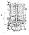
Fig. 1 is a cross-sectional diagram showing a vane-type compressor in embodiments according to the present invention; -
Fig. 2 is a cross sectional diagram of a compression unit in the compressor shown inFig. 1 ; -
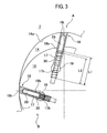
Fig. 3 is a cross-sectional diagram of vanes in a first embodiment according to the present invention; -
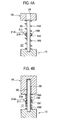
Fig. 4A is a cross-sectional diagram showing an environment of vanes (at coil springs being expanded) in a second embodiment according to the present invention; -
Fig. 4B is a cross-sectional diagram showing an environment of vanes (at coil springs being compressed) in the second embodiment according to the present invention; -
Fig. 5A is a cross-sectional diagram showing an environment of vanes (at coil springs being expanded) in a first modified example of the second embodiment according to the present invention; -
Fig. 5B is a cross-sectional diagram showing an environment of vanes (at coil springs being compressed) in the first modified example of the second embodiment according to the present invention; -
Fig. 6A is a cross-sectional diagram showing an environment of vanes (at coil springs being expanded) in a second modified example of the second embodiment according to the present invention; -
Fig. 6B is a cross-sectional diagram showing an environment of vanes (at coil springs being compressed) in the second modified example of the second embodiment according to the present invention; -
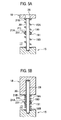
Fig. 7A is a cross-sectional diagram showing an environment of vanes (at coil springs being expanded) in a third embodiment according to the present invention; -
Fig. 7B is a cross-sectional diagram showing an environment of vanes (at coil springs being compressed) in the third embodiment according to the present invention; -
Fig. 8A is a cross-sectional diagram showing an environment of vanes (at coil springs being expanded) in a modified example of the third embodiment according to the present invention; -
Fig. 8B is a cross-sectional diagram showing an environment of vanes (at coil springs being compressed) in the modified example of the third embodiment according to the present invention; -
Fig. 9A is a cross-sectional diagram of a vane (being projected) in a fourth embodiment according to the present invention; -
Fig. 9B is a cross-sectional diagram of the vane (being accommodated in a vane slot) in the fourth embodiment according to the present invention; -
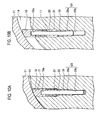
Fig. 10A is a cross-sectional diagram along a line XA - XA shown inFig. 9A ; -
Fig. 10B is a cross-sectional diagram along a line XB - XB shown inFig. 9B ; and -
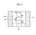
Fig. 11 is a side view showing dimensions of a guide pin and a coil spring in the fourth embodiment. - Hereinafter, embodiments of the prevent invention will be explained with reference to diagrams. First, a first embodiment will be explained with reference to
Figs. 1 to 3 . - As shown in
Fig. 1 , a compressor 1 includes ahousing 2. Thehousing 2 is configured with an almosttubular compressor housing 3, afront housing 4 provided on one opening end of thecompressor housing 3 and amotor housing 5 provided on another opening end of thecompressor housing 3. Thecompressor housings 3, thefront housing 4 and themotor housing 5 are all made of aluminum alloy. - A
compression unit 10 is accommodated within thecompressor housing 3. The compression unit includes acylinder block 10, afront block 12 and a rear block both provided besides thecylinder block 11. Theseblocks bolts 10a (seeFig. 2 ). Acompression chamber 14 is formed within theblocks blocks housings - As shown in
Fig. 2 , acircular rotor 15 is accommodated within theellipsoidal compression chamber 14. Arotor axis 16 penetrates the center of therotor 15 and is fixed with therotor 15. Therotor axis 16 is rotatably supported by thefront block 12 and therear block 13. The rear end of therotor axis 16 projects outward from therear block 13. -
Vane slots 17 are provided on the outer circumference of therotor 15 at even intervals and extend in radial directions. Avane 18 is provided within each of thevane slots 17 and is capable of reciprocating within each of thevane slots 17. A refrigerant supply path (not shown) is opened at each bottom of thevane slots 17. (Note that additional high-pressure supply paths are not provided in the present embodiment.) Each of thevanes 18 is urged outward in its projecting direction by both back pressure due to the supplied refrigerant and elastic restoring force of a coil spring 19 (seeFig. 3 ). As rotating speed of therotor 15 arises, a centrifugal force applied to each of thevanes 18 also urge it outward in the projecting direction. Thevanes 18 reciprocate within thevane slots 17 with being contacted with an inner wall (a cam face) 14a of thecompression chamber 14 by the above urging force in the projecting direction during therotor axis 16 rotating. Thecompression chamber 14 is sectioned into plural chambers by thevanes 18. Each of the sectioned chambers repeats an intake process to intake refrigerant therein by enlarging its inner volume and a compression process to compress and discharge the refrigerant by reducing its inner volume. -
Intake paths 20 are provided in thecylinder block 11 and so on and located at two positions opposed across therotor axis 16. Each of theintake paths 20 includes anintake chamber 20a and anintake opening 20b communicating theintake chamber 20a and thecompression chamber 14.Discharge paths 21 are also provided in thecylinder block 11 and so on and located at two positions opposed across therotor axis 16. Each of thedischarge paths 21 includes adischarge chamber 21a and adischarge opening 21b communicating thedischarge chamber 21a and thecompression chamber 14. - As shown in
Fig. 1 , amotor 6 is accommodated within themotor housing 5. Themotor 6 includes arotor 23 fixed with amotor axis 22 and astator 24 fixed on an inner circumferential surface of themotor housing 5. Both ends of themotor axis 22 are rotatably supported by themotor housing 5 and therear block 13 viaball bearings motor axis 22 is connected with therotor axis 16. Therotor 23 is magnetized with north and south magnetic poles alternately along its circumferential direction. Thestator 24 is configured with a core (mot shown) made of ferromagnetic material and a coil (not shown) wound around the core. Driving current is supplied to the coil by amotor controller 26 configured with an inverter and so on. Themotor controller 26 is installed on thefront housing 4. - Rotation of the
motor 6 is transmitted from themotor axis 22 to therotor axis 16 and then therotor 15 is rotated. The refrigerant compressed within thecompression chamber 14 due to therotor 15 rotating is sent into themotor housing 6 viadischarge holes 21c. Oil included in the refrigerant is separated by an oil separator after the refrigerant has cooled therotor 23 and thestator 24 and then the refrigerant is discharged outside the compressor 1 from adischarge port 27. The discharged refrigerant is sent to a condenser and so on. - As shown in
Fig. 3 , guide pins 30 are directly fixed on the bottoms of thevane slots 17. In the present embodiment, two guide pins 30 are press-fitted to be fixed onto each bottom of thevane slots 17. In addition, twoguide holes 28 are formed on each of thevanes 18 to accommodate the reciprocating guide pins 30. Each of the guide pins 30 is inserted into each inside of the coil springs 19. As mentioned above, the coil springs 19 urges thevanes 18 outward to contact their top end edges onto thecam face 14a. One end of thecoil spring 19 contacts with a bottom surface of thevane 18 and another end thereof contacts with the bottom of thevane slot 17. Theguide pin 30 functions to prevent serpentine flection of thecompressed coil spring 19. Since serpentine flections of the coil springs 19 are prevented, the coil springs 19 never are stuck between the bottoms of thevane slots 17 and the bottom surfaces of thevanes 18. - A condition indicated by an arrow A in
Fig. 3 shows a condition where a projecting amount of thevane 18 from thevane slot 17 is maximum (an expanded condition of the coil spring 19). A condition indicated by an arrow B inFig. 3 shows a condition where entire of thevane 18 is accommodated within the vane slot 17 (a compressed condition of the coil spring 19). An inner diameter of theguide hole 18 is made smaller than an outer diameter of thecoil spring 19, so that thecoil spring 19 cannot enter the inside of theguide hole 18. Therefore, abase end 18a of thevane 18 always contacts with the one end of thecoil spring 19. In addition, the inner diameter of theguide hole 18 is made slightly larger than an outer diameter of theguide pin 30. Theguide pin 30 is always inserted within theguide hole 28 at least partly. - The
coil spring 19 presses thevane 18 so as to contact thetop end 18t of thevane 18 onto thecam face 14a along with therotor 15 rotating. In addition, thevane 18 is pressed back toward the inside of thevane slot 17 by a reaction force received from thecam face 14a. A position of thevane 18 varies between the above-mentioned conditions A and B to reciprocate within thevane slot 17. - In the condition A where the
coil spring 19 is expanded most, misalignment of thecoil spring 19 is prevented by theguide pin 30 being longer than thecoil spring 19. In addition, in the condition A, a projecting amount of thevane 18 is maximum, so that chattering of thevane 18 hardly occurs. Further, since a load by thecoil spring 19 is minimum, it is preferable in terms of friction reduction between thevane 18 and thecam face 14a and attrition reduction. Furthermore, thecoil spring 19 is sufficiently long so as not to occur a play (gap) between thevane 18 and thecoil spring 19 even when the projecting amount is maximum. - In the condition B where the
coil spring 19 is compressed most, an inserted amount of thevane 18 into thevane slot 17 is maximum and thereby chattering of thevane 18 tends to occur. However, since the load by thecoil spring 19 is maximum, chattering of thevane 18 is prevented. In addition, though thecoil spring 19 is made compressed most, its serpentine flection is prevented by theguide pin 30. Further, stuck of thecoil spring 19 due to its serpentine flection is also prevented. - As explained above, the
vanes 18 are pressed toward thecam face 14 by the coil springs 19 for prevention of chattering in order to assist the back pressure in thevane slots 17. Therefore, it is not necessary to add additional high-pressure supply paths and spring-driven valves. As a result, a complex structure and cost rise are prevented. - In addition, serpentine flection of the coil springs 19 and stuck of the coil springs 19 due to the serpentine flection can be prevented by the guide pins 30.
- Further, since the guide pins 30 is longer than the expanded coil springs 19, the
coil spring 19 never be misaligned when they are expanded most as in the conventional vane pump. - Furthermore, since the guide pins 30 are press-fitted to be fixed onto the
bottoms 17b of thevane slots 17, any extra component is not necessary to fix the guide pins as in the conventional vane pump. Therefore, component incrementation and cost rise can be prevented. - Next, a second embodiment will be explained with reference to
Figs. 4A and 4B . Note that a general configuration of the compressor 1 is the same as that in the first embodiment (seeFigs. 1 and2 ) and thereby redundant explanations will be omitted. Configurations around vanes (especially, coil springs) are different between the present embodiment and the first embodiment. - As shown in
Figs. 4A and 4B , the guide pins 30 are press-fitted onto the bottoms of thevane slots 17. A projecting length of theguide pin 30 from the bottom is longer than a total length of expandedcoil springs slider 21A. Theslider 21A is composed of atubular element 21t inserted into the coil springs 19A, 19B and aflange 21f extended outward from thetubular element 21t. An outer diameter of thetubular element 21t is slightly smaller than each inner diameter of the coil springs 19A, 19B. The coil springs 19A, 19B have the same length. Each of opposed end of the coil springs 19A, 19B is received by theflange 21f. Theslider 21A is sandwiched between the coil springs 19A, 19B to prevent the coil springs 19A, 19B from contacting with theguide pin 30. -
Fig 4A shows a condition where a projecting amount of thevane 18 is maximum (an expanded condition of the coil springs 19A, 19B).Fig 4B shows a condition where entire of thevane 18 is accommodated within the vane slot 17 (a compressed condition of the coil springs 19A, 19B). Theguide hole 28, into which theguide pin 30 is inserted, is provided in thevane 18. The inner diameter of theguide hole 28 is slightly larger than the outer diameter of theguide pin 30. In addition, the inner diameter of theguide hole 28 is smaller than the outer diameter of thecoil spring 19A and the bottom surface of thevane 18 contacts with an end of thecoil spring 19A. - A position of the
vane 18 varies between the above-mentioned conditions shown inFigs. 4A and 4B to reciprocate within thevane slot 17 with therotor 15 rotating. At this time, theslider 21A (thetubular element 21t) reciprocates along theguide pin 30 along with expansion and compression of the coil springs 19A, 19B. This reciprocation of thetubular element 21t is done with sliding on the outer surface of theguide pin 30, so that the coil springs 19A, 19B never contacts with theguide pin 30. - In the condition shown in
Fig. 4A where the coil springs 19A, 19B are expanded most, misalignment of the coil springs 19A, 19B is prevented by theguide pin 30 being longer than the total length of the coil springs 19A, 19B. In addition, a projecting amount of thevane 18 is maximum, so that chattering of thevane 18 hardly occurs. Further, since a load by the coil springs 19A, 19B is minimum, it is preferable in terms of friction reduction between thevane 18 and thecam face 14a and attrition reduction. Furthermore, the total length of the coil springs 19A, 19B is sufficiently long so as not to occur a play (gap) between thevane 18 and thecoil springs 19a, 19B even when the projecting amount is maximum. - In the condition shown in
Fig. 4B where the coil springs 19A, 19B are compressed most, an inserted amount of thevane 18 into thevane slot 17 is maximum and thereby chattering of thevane 18 tends to occur. However, since the load by the coil springs 19A, 19B is maximum, chattering of thevane 18 is prevented. In addition, serpentine flection of thecoil springs 19a, 19B hardly occur because each length of the coil springs 19A, 19B is made short due to arrangement of theslider 21A. As a result, it is prevented that the coil springs 19A, 19B contacts with theguide pin 30 due to their serpentine flections. - As explained above, contacts between the coil springs 19A, 19B and the
guide pin 30 is prevented by theslider 21A. Therefore, alteration of spring constant or breakage of the coil springs 19A, 19B due to their attrition is prevented. In addition, attrition of theguide pin 30 is also prevented. - In addition, since the
slider 21A is arranged between the even-length coil springs guide pin 30 are prevented more effectively. - Further, the
coil spring 19 is divided into the twocoil springs slider 21A. Therefore, each length of the coil springs 19A, 19B is made short and thereby their serpentine flections are prevented. As a result, their contacts with theguide pin 30 due to the serpentine flections are prevented. - Furthermore, the projecting length of the
guide pin 30 from the bottom of thevane slot 17 is made longer than the total length of the coil springs 19A, 19B and theslider 21A (theflange 21f). Therefore, thecoil springs 19a, 19B is guided firmly by theguide pin 30 even when they are expanded most and thereby their contacts with the inner wall of thevane slot 17 due to their serpentine flections are prevented. - Furthermore, since chattering of the
vane 18 is prevented by the coil springs 19A, 19B, it is not necessary to provide high-pressure supply paths or spring-driven valves. As a result, a complex structure and cost rise can be prevented. - Furthermore, since the guide pins 30 are press-fitted onto the bottoms of the
vane slots 17, any extra component (such as the support plate) is not necessary to fix the guide pins 30. As a result, component incrementation and cost rise can be prevented. - A first modified example of the second embodiment is shown in
Figs. 5A and 5B . - In the first modified example, a
spacer 21B is provided between another end of thecoil spring 19A and the bottom surface of thevane 18. Thespacer 21B projects toward the inside of thecoil spring 19A. - According to the first modified example, compared with the above second embodiment, contacts between the other end of the
coil spring 19A and theguide pin 30 can be prevented. Therefore, attrition and breakage of the other end (movable end in relation to the guide pin 30) of thecoil spring 19A can be prevented. - A second modified example of the second embodiment is shown in
Figs. 6A and 6B . - In the second modified example, the
spacer 21B and aspacer 21C are provided between the other end of thecoil spring 19A and the bottom surface of thevane 18 and between the other end of thecoil spring 19B and the bottom of thevane slot 17. Thespacers - According to the second modified example, compared with the above second embodiment, contacts between the other ends of the coil springs 19A, 19B and the
guide pin 30 can be prevented. Therefore, attrition and breakage of the other ends (movable end and fixed end in relation to the guide pin 30) of the coil springs 19A, 19B can be prevented. - Note that three or more coil springs may be used for each guide pin. In addition, coil springs for one guide pin may have different lengths and two or more slider may be provided for each guide pin.
- Next, a third embodiment will be explained with reference to
Figs. 7A and 7B . Note that a general configuration of the compressor 1 is the same as that in the first embodiment (seeFigs. 1 and2 ) and thereby redundant explanations will be omitted. Configurations around vanes (especially, coil springs) are different between the present embodiment and the first embodiment. - As shown in
Fig. 7A and 7B , the guide pins 30 are press-fitted onto the bottoms of thevane slots 17. The guide pins 20 stand within thevane slots 17. - The guide holes 28 are provided on the bottom surface of the
vanes 18. Thevanes 18 can reciprocate so that the guide pins 30 are inserted into the guide holes 28. - The
guide pin 30 is inserted into acoil spring 19C. one end of thecoil spring 19C contacts with the bottom surface of thevane 18 and another end thereof contacts with the bottom of thevane slot 17. thecoil spring 19C has a zero-pitch portion 192, at which a winding pitch of a spring wire is made zero, at its middle along its axial direction. The zero-pitch portion 192 is formed by attaching the wound spring wire each winding due to a winding device setting. - The
rotor 15 rotates on themotor 6 being driven and some of the refrigerant compressed by thevanes 18 within thecompression chamber 14 is supplied to the refrigerant supply paths (not shown) provided at the bottoms of thevane slots 17. Therefore, back pressure by the refrigerant is supplied to the base ends of thevanes 18, so that thevanes 18 are urged in the projecting direction by the back pressure and the elastic restoring forces of the coil springs 19C. Since a load by thecoil spring 19C is applied to thevane 18 even at starting of compression when the back pressure can not be applied, chattering of thevane 18 never occurs. - In addition, the
coil spring 19C repeats its expansion and compression along with thevane 18 reciprocating while thecompression unit 10 being driven. If thecoil spring 19C serpentines at its compression, an inner circumference of the zero-pitch portion 192 contacts with theguide pin 30. Therefore, the zero-pitch portion 192 may be worn away. However, since the spring wire is contacted each winding at the zero-pitch portion 192, stress is not supplied to the zero-pitch portion 192 due to the expansion and the compression. As a result, the zero-pitch portion 192 may be worn away but never brings its fatigue breakage. - A modified example of the third embodiment is shown in
Figs. 8A and 8B . - In this modified example, an inner diameter of a zero-
pitch portion 193 of acoil spring 19D is made smaller than an inner diameter of other portions (except for the zero-pitch portion 193). - According to this modified embodiment, the zero-
pitch portion 193 having the smaller diameter contacts with theguide pin 30 firmly when the coil spring 19d serpentines, so that the other portions never contact with theguide pin 30. Therefore, fatigue breakage of thecoil spring 19D can be prevented firmly. - Note that one zero-
pitch portion coil spring - Next, a fourth embodiment will be explained with reference to
Figs. 9A and11 . Note that a general configuration of the compressor 1 is the same as that in the first embodiment (seeFigs. 1 and2 ) and thereby redundant explanations will be omitted. Configurations around vanes (especially, coil springs and guide pins) are different between the present embodiment and the first embodiment. - As shown in
Figs. 9A to 10B ,plural recesses 18a are formed on the bottom surface of thevanes 18. The guide pins 18 are press-fitted into therecesses 18a. Specifically, theguide pin 30 is directly fixed on thevane 18 by being press-fitted. Theguide pin 30 has a length capable of covering the whole length of thecoil spring 19 at the maximum projected position of the vane 18 (seeFigs. 9B and10B ). - A
refrigerant supply path 31 is opened at the bottom of thevane slot 17. Refrigerant supplied through therefrigerant supply path 31 applies to thevane 18 as back pressure. In addition, guide holes 29 are opened on the bottom of thevane slots 17. Theguide hole 29 composed of anaccommodating space 29a opened on the bottom of thevane slot 17 and an insertedspace 29b communicating with theaccommodating space 29a. A step is made at the border between theaccommodating space 29a and the insertedspace 29b. An end of thecoil spring 19 is received by the step. - The
guide pin 30 is inserted into thecoil spring 19. One end of thecoil spring 19 contacts with the bottom surface of thevane 19 and another end thereof contacts with the above-mentioned step. In other words, thecoil spring 19 is accommodated within thevane slot 17 and theaccommodating space 29a of theguide hole 29. - As shown in
Fig. 11 , when an outer diameter of theguide pin 30 shall be a, an inner diameter of thecoil spring 19 shall be b1 and its outer diameter shall be b2, and an inner diameter of theaccommodating space 29a shall be c, an inequality (b1 - a) < (c - b2) is met. - The
rotor 15 rotates on themotor 6 being driven and some of the refrigerant compressed by thevanes 18 within thecompression chamber 14 is supplied to therefrigerant supply paths 31. Therefore, back pressure by the refrigerant is supplied to the base ends of thevanes 18, so that thevanes 18 are urged in the projecting direction by the back pressure and the elastic restoring forces of the coil springs 19C. Since a load by thecoil spring 19C is applied to thevane 18 even at starting of compression when the back pressure can not be applied, chattering of thevane 18 never occurs. - Since the guide pins 30 for guiding the coil springs 19 are directly fixed onto the
vanes 18, a work needed to be done within thevane slot 17 is only a work providing theguide hole 29 which does not need high accuracy. In addition, checking work after fixing the guide pins 30 can be done before setting thevanes 18, onto which the guide pins 30 had been already fixed, in thevane slots 17. Therefore, manufacturing, fixing and checking works for the guide pins 30 can be done more easily. - In the present embodiment, the
guide pin 30 has the length capable of covering the whole length of thecoil spring 19 at the maximum projected position of the vane 18 (seeFigs. 9B and10B ). Therefore, stuck of thecoil spring 19 due to its serpentine flection can be prevented firmly. - In the present embodiment, the inequality (b1 - a) < (c - b2) is met as explained above. Therefore, the
coil spring 19 never contacts with an inner wall of theaccommodating space 29a if thecoil spring 19 serpentines. As a result, smooth expansion and compression of thecoil spring 19 can be achieved. - In the present embodiment, the guide pins are directly fixed onto the
vanes 18 by being press-fitted. Therefore, the guide pins 30 are easily fixed on thevanes 18 with high-accuracy. It is preferable that the guide pins 20 are press-fitted into thevanes 18. However, they may be directly fixed on thevanes 18 by screw-fixing, glue-fixing or the like. Alternatively, thevane 18 and the guide pins 30 may be formed integrally (for example, by grinding process). - Note that the vane-type compressor according to the present invention is not limited to the above embodiments and can be varied within the technical scope of the present invention.
- In addition, the vane-type compressor according to the present invention can be applied to limited-slip differential device using high-viscosity oil as working fluid in a drive train for a vehicle other than the above-mentioned refrigerating system using refrigerant.
- Further, a drive source of the vane-type compressor according to the present invention may be an internal combustion engine or the like other than the above electric motor. Furthermore, the drive source may not be unitized with the compressor as mentioned above. The compressor may be driven using a pulley.
Claims (13)
- A vane-type compressor (1) comprising:a cylinder block (11);a rotor (15) rotating within the cylinder block (11);a plurality of vane slots (17) provided on an outer surface of the rotor (15) and extending inwardly;a plurality of vanes (18) each provided slidably within each of the plurality of vane slots (17) and reciprocating as to contact a top end thereof onto an inner surface (14a) of the cylinder block (11) along with the rotor (15) rotating;a plurality of coil springs (19) provided within the plurality of vane slots (17) for pushing the plurality of vanes (18) toward the inner surface (14a);a plurality of guide pins (30) each provided along each of the plurality of coil springs (19) and directly fixed on the plurality of vanes (18) or the rotor (15); anda plurality of guide holes (28, 29) each provided for each of the plurality of guide pins (30) and formed on the rotor (15) or the plurality of vanes (18), whereinthe plurality of guide holes (28, 29) is formed on the plurality of vanes (18) in case where the plurality of guide pins (30) is directly fixed on the rotor (15), orthe plurality of guide holes (28, 29) is formed on the rotor (15) in case where the plurality of guide pins (30) is directly fixed on the plurality of vanes (18).
- The vane-type compressor (1) according to claim 1, wherein
the plurality of the guide pins (30) is directly fixed on the rotor (15) and the plurality of guide holes (28) is formed on the plurality of vanes (18), and
the plurality of coil springs (19) contacts with base ends (18b) of the plurality of vanes (18) and does not enters into the plurality of guide holes (28). - The vane-type compressor (1) according to claim 2, wherein
each of the plurality of guide pins (30) is provided within each of the coil springs (19), and is longer than each of the plurality of coil springs (19) under a most extending condition. - The vane-type compressor (1) according to claim 3, wherein
the plurality of guide pins (30) is fixed on bottoms (17b) of the plurality of vane slots (17). - The vane-type compressor (1) according to claim 4, wherein
the plurality of guide pins (30) is press-fitted onto the bottoms (17b) of the plurality of vane slots (17). - The vane-type compressor according to claim 1, wherein
the plurality of the guide pins (30) is directly fixed on the rotor (15) and the plurality of guide holes (28) is formed on the plurality of vanes (18),
each of the plurality of guide pins (30) is provided within each of the coil springs (19),
each of the plurality of coil springs (19) provided for each of the guide pins (30) composed of at least two coil springs (19A, 19B) jointed axially each other, and
a slider (21A) is provided between the jointed coil springs (19A, 19B) and projects into insides of the jointed coil springs (19A, 19B). - The vane-type compressor (1) according to claim 6, wherein
a spacer (21B, 21C) is provided between each of the plurality of coil springs (19) and each base end of the plurality of vanes (18) or between each of the plurality of coil springs (19) and each bottom of the plurality of vane slots (17). - The vane-type compressor (1) according to claim 1, wherein
the plurality of the guide pins (30) is directly fixed on the rotor (15) and the plurality of guide holes (28) is formed on the plurality of vanes (18),
each of the plurality of guide pins (30) is provided within each of the coil springs (19C, 19D), and
each of the plurality of coil springs (19C, 19D) includes a zero-pitch portion (192, 193), at which a winding pitch is made zero, at middle thereof along an axial direction thereof. - The vane-type compressor (1) according to claim 8, wherein
an inner diameter of the zero-pitch portion (193) is made smaller than an inner diameter of other portions except for the zero-pitch portion (193). - The vane-type compressor (1) according to claim 1, wherein
the plurality of the guide pins (30) is directly fixed on the plurality of the vanes (18) and the plurality of guide holes (29) is formed on the rotor (15), and
each of the plurality of guide pins (30) is provided within each of the coil springs (19). - The vane-type compressor (1) according to claim 10, wherein
each of the plurality of guide pins (30) has a length capable of guiding an entire length of each of the coil springs (19) when each of the plurality of vanes (18) projects most. - The vane-type compressor (1) according to claim 11, wherein
each of the plurality of coil springs (19) are accommodated in an accommodating space (29a) provided in the rotor (15), and
an inequality (b1 - a) < (c - b2) is met when each outer diameter of the plurality of the guide pins (30) shall be a, each inner diameter of the plurality of coil springs (19) shall be b1 and each outer diameter thereof shall be b2, and an inner diameter of the accommodating space (29a) shall be c. - The vane-type compressor (1) according to claim 12, wherein
the plurality of guide pins (30) is press-fitted onto the plurality of vanes (18).
Applications Claiming Priority (4)
| Application Number | Priority Date | Filing Date | Title |
|---|---|---|---|
| JP2007332645A JP2009156088A (en) | 2007-12-25 | 2007-12-25 | Vane type compressor unit |
| JP2008013937A JP4382852B2 (en) | 2008-01-24 | 2008-01-24 | Vane compressor |
| JP2008051092A JP4459275B2 (en) | 2008-02-29 | 2008-02-29 | compressor |
| JP2008067743A JP4382853B2 (en) | 2008-03-17 | 2008-03-17 | compressor |
Publications (3)
| Publication Number | Publication Date |
|---|---|
| EP2075405A2 true EP2075405A2 (en) | 2009-07-01 |
| EP2075405A3 EP2075405A3 (en) | 2014-01-01 |
| EP2075405B1 EP2075405B1 (en) | 2015-10-14 |
Family
ID=40547934
Family Applications (1)
| Application Number | Title | Priority Date | Filing Date |
|---|---|---|---|
| EP08022038.7A Not-in-force EP2075405B1 (en) | 2007-12-25 | 2008-12-18 | Vane-type compressor |
Country Status (2)
| Country | Link |
|---|---|
| US (1) | US8257072B2 (en) |
| EP (1) | EP2075405B1 (en) |
Cited By (1)
| Publication number | Priority date | Publication date | Assignee | Title |
|---|---|---|---|---|
| EP2728191A4 (en) * | 2011-06-28 | 2015-01-21 | Calsonic Kansei Corp | Vane compressor |
Families Citing this family (9)
| Publication number | Priority date | Publication date | Assignee | Title |
|---|---|---|---|---|
| JP5433400B2 (en) * | 2009-12-24 | 2014-03-05 | カルソニックカンセイ株式会社 | Vane type compressor |
| JP5751215B2 (en) * | 2012-06-19 | 2015-07-22 | 株式会社豊田自動織機 | Tandem vane compressor |
| CN103953544B (en) | 2014-04-10 | 2016-01-27 | 珠海格力节能环保制冷技术研究中心有限公司 | Compressor and air conditioner |
| JP6413956B2 (en) * | 2015-06-30 | 2018-10-31 | 株式会社豊田自動織機 | Vane type compressor |
| MX2018006924A (en) * | 2016-12-09 | 2018-08-15 | Stackpole Int Engineered Products Ltd | Vane pump with one or more less restricted vanes. |
| KR102223283B1 (en) * | 2018-11-16 | 2021-03-05 | 엘지전자 주식회사 | Vain rotary compressor |
| KR102522994B1 (en) | 2021-10-28 | 2023-04-19 | 엘지전자 주식회사 | Rotary compressor |
| KR102545597B1 (en) * | 2022-01-14 | 2023-06-21 | 엘지전자 주식회사 | Rotary compressor |
| CN114472339B (en) * | 2022-01-24 | 2023-08-15 | 南通科技职业学院 | A high-efficient screening equipment that washs for traditional chinese medicine |
Citations (2)
| Publication number | Priority date | Publication date | Assignee | Title |
|---|---|---|---|---|
| JPH08538Y2 (en) | 1990-03-24 | 1996-01-10 | 光洋精工株式会社 | Vane pump |
| JP2007100602A (en) | 2005-10-05 | 2007-04-19 | Calsonic Compressor Inc | Gas compressor |
Family Cites Families (12)
| Publication number | Priority date | Publication date | Assignee | Title |
|---|---|---|---|---|
| US508555A (en) * | 1893-11-14 | Rotary engine | ||
| US461533A (en) * | 1891-10-20 | Water-meter | ||
| US582280A (en) * | 1897-05-11 | Rotary fluid-meter | ||
| DE425688C (en) * | 1926-02-22 | Otto Sorge | Device to relieve the pistons of rotary lobe pumps by means of springs | |
| US1628058A (en) * | 1925-02-05 | 1927-05-10 | M R Humpton | Metering pump |
| US1913758A (en) * | 1930-01-10 | 1933-06-13 | Margaret A Kerr | Rotary pump |
| JPS51154405U (en) | 1975-06-04 | 1976-12-09 | ||
| JPS5293905U (en) | 1976-01-09 | 1977-07-13 | ||
| JPS55104502A (en) | 1979-01-31 | 1980-08-11 | Matsushita Electric Ind Co Ltd | Sliding vane type expander |
| JPS55140782U (en) | 1979-03-30 | 1980-10-07 | ||
| DE3015409A1 (en) * | 1980-04-22 | 1981-10-29 | Robert Bosch Gmbh, 7000 Stuttgart | ROTATING VACUUM PUMP |
| JPH1159900A (en) * | 1997-08-22 | 1999-03-02 | Mitsui High Tec Inc | Atmosphere converter for transporting granular materials |
-
2008
- 2008-12-18 EP EP08022038.7A patent/EP2075405B1/en not_active Not-in-force
- 2008-12-23 US US12/342,766 patent/US8257072B2/en not_active Expired - Fee Related
Patent Citations (2)
| Publication number | Priority date | Publication date | Assignee | Title |
|---|---|---|---|---|
| JPH08538Y2 (en) | 1990-03-24 | 1996-01-10 | 光洋精工株式会社 | Vane pump |
| JP2007100602A (en) | 2005-10-05 | 2007-04-19 | Calsonic Compressor Inc | Gas compressor |
Cited By (1)
| Publication number | Priority date | Publication date | Assignee | Title |
|---|---|---|---|---|
| EP2728191A4 (en) * | 2011-06-28 | 2015-01-21 | Calsonic Kansei Corp | Vane compressor |
Also Published As
| Publication number | Publication date |
|---|---|
| US20090162234A1 (en) | 2009-06-25 |
| EP2075405B1 (en) | 2015-10-14 |
| EP2075405A3 (en) | 2014-01-01 |
| US8257072B2 (en) | 2012-09-04 |
Similar Documents
| Publication | Publication Date | Title |
|---|---|---|
| EP2075405B1 (en) | Vane-type compressor | |
| US8944784B2 (en) | Compressor and motor device thereof | |
| US11067079B2 (en) | Scroll compressor | |
| US10215026B2 (en) | Pump module and electric pump including the same | |
| US11286930B2 (en) | Scroll compressor having recessed outer fixed scroll wall | |
| CN103486040B (en) | Rotary compressor | |
| US20170284396A1 (en) | Electric compressor | |
| CN104641115B (en) | Rotary compressor | |
| CN101469707A (en) | Vane-type compressor | |
| US8029254B2 (en) | Scroll-type fluid machine having a back-pressure chamber | |
| US20170284395A1 (en) | Electric compressor | |
| EP2728191A1 (en) | Vane compressor | |
| CN100439715C (en) | electric compressor | |
| CN104508303B (en) | Motor compressor | |
| CN102808770B (en) | Multi-cylinder rotary compressor | |
| CN100416098C (en) | Cylinder support structure of reciprocating compressor | |
| JP2005139935A (en) | Scroll compressor | |
| JP4382852B2 (en) | Vane compressor | |
| US20250237216A1 (en) | Electric compressor | |
| US20190203710A1 (en) | Motor operated compressor | |
| WO2017047338A1 (en) | Hermetic electric compressor | |
| JP5807149B2 (en) | Fluid machine and stator fixing method for fluid machine | |
| JP4459275B2 (en) | compressor | |
| KR102043153B1 (en) | Linear compressor | |
| JP2012021473A (en) | Electric compressor |
Legal Events
| Date | Code | Title | Description |
|---|---|---|---|
| PUAI | Public reference made under article 153(3) epc to a published international application that has entered the european phase |
Free format text: ORIGINAL CODE: 0009012 |
|
| AK | Designated contracting states |
Kind code of ref document: A2 Designated state(s): AT BE BG CH CY CZ DE DK EE ES FI FR GB GR HR HU IE IS IT LI LT LU LV MC MT NL NO PL PT RO SE SI SK TR |
|
| AX | Request for extension of the european patent |
Extension state: AL BA MK RS |
|
| PUAL | Search report despatched |
Free format text: ORIGINAL CODE: 0009013 |
|
| AK | Designated contracting states |
Kind code of ref document: A3 Designated state(s): AT BE BG CH CY CZ DE DK EE ES FI FR GB GR HR HU IE IS IT LI LT LU LV MC MT NL NO PL PT RO SE SI SK TR |
|
| AX | Request for extension of the european patent |
Extension state: AL BA MK RS |
|
| RIC1 | Information provided on ipc code assigned before grant |
Ipc: F04C 18/344 20060101ALI20131125BHEP Ipc: F04C 23/00 20060101ALI20131125BHEP Ipc: F01C 21/08 20060101AFI20131125BHEP |
|
| 17P | Request for examination filed |
Effective date: 20140514 |
|
| RBV | Designated contracting states (corrected) |
Designated state(s): AT BE BG CH CY CZ DE DK EE ES FI FR GB GR HR HU IE IS IT LI LT LU LV MC MT NL NO PL PT RO SE SI SK TR |
|
| AKX | Designation fees paid |
Designated state(s): DE FR GB |
|
| GRAP | Despatch of communication of intention to grant a patent |
Free format text: ORIGINAL CODE: EPIDOSNIGR1 |
|
| INTG | Intention to grant announced |
Effective date: 20150601 |
|
| GRAS | Grant fee paid |
Free format text: ORIGINAL CODE: EPIDOSNIGR3 |
|
| GRAA | (expected) grant |
Free format text: ORIGINAL CODE: 0009210 |
|
| AK | Designated contracting states |
Kind code of ref document: B1 Designated state(s): DE FR GB |
|
| REG | Reference to a national code |
Ref country code: GB Ref legal event code: FG4D |
|
| REG | Reference to a national code |
Ref country code: DE Ref legal event code: R096 Ref document number: 602008040612 Country of ref document: DE |
|
| REG | Reference to a national code |
Ref country code: FR Ref legal event code: PLFP Year of fee payment: 8 |
|
| PGFP | Annual fee paid to national office [announced via postgrant information from national office to epo] |
Ref country code: GB Payment date: 20151216 Year of fee payment: 8 Ref country code: DE Payment date: 20151215 Year of fee payment: 8 |
|
| PGFP | Annual fee paid to national office [announced via postgrant information from national office to epo] |
Ref country code: FR Payment date: 20151208 Year of fee payment: 8 |
|
| REG | Reference to a national code |
Ref country code: DE Ref legal event code: R097 Ref document number: 602008040612 Country of ref document: DE |
|
| PLBE | No opposition filed within time limit |
Free format text: ORIGINAL CODE: 0009261 |
|
| STAA | Information on the status of an ep patent application or granted ep patent |
Free format text: STATUS: NO OPPOSITION FILED WITHIN TIME LIMIT |
|
| 26N | No opposition filed |
Effective date: 20160715 |
|
| REG | Reference to a national code |
Ref country code: DE Ref legal event code: R119 Ref document number: 602008040612 Country of ref document: DE |
|
| GBPC | Gb: european patent ceased through non-payment of renewal fee |
Effective date: 20161218 |
|
| REG | Reference to a national code |
Ref country code: FR Ref legal event code: ST Effective date: 20170831 |
|
| PG25 | Lapsed in a contracting state [announced via postgrant information from national office to epo] |
Ref country code: FR Free format text: LAPSE BECAUSE OF NON-PAYMENT OF DUE FEES Effective date: 20170102 |
|
| PG25 | Lapsed in a contracting state [announced via postgrant information from national office to epo] |
Ref country code: GB Free format text: LAPSE BECAUSE OF NON-PAYMENT OF DUE FEES Effective date: 20161218 Ref country code: DE Free format text: LAPSE BECAUSE OF NON-PAYMENT OF DUE FEES Effective date: 20170701 |