EP2074418B1 - Ultrasonic determination of optical absorption coefficients - Google Patents
Ultrasonic determination of optical absorption coefficients Download PDFInfo
- Publication number
- EP2074418B1 EP2074418B1 EP07826422A EP07826422A EP2074418B1 EP 2074418 B1 EP2074418 B1 EP 2074418B1 EP 07826422 A EP07826422 A EP 07826422A EP 07826422 A EP07826422 A EP 07826422A EP 2074418 B1 EP2074418 B1 EP 2074418B1
- Authority
- EP
- European Patent Office
- Prior art keywords
- measuring location
- light beam
- optical
- coefficient
- measuring
- Prior art date
- Legal status (The legal status is an assumption and is not a legal conclusion. Google has not performed a legal analysis and makes no representation as to the accuracy of the status listed.)
- Not-in-force
Links
- 230000003287 optical effect Effects 0.000 title claims description 57
- 238000010521 absorption reaction Methods 0.000 title claims description 24
- 238000010438 heat treatment Methods 0.000 claims description 35
- 238000000034 method Methods 0.000 claims description 27
- 238000002592 echocardiography Methods 0.000 claims description 20
- 238000011156 evaluation Methods 0.000 claims description 14
- 238000013507 mapping Methods 0.000 claims description 14
- 239000002872 contrast media Substances 0.000 claims description 7
- 230000003595 spectral effect Effects 0.000 claims description 6
- 239000000203 mixture Substances 0.000 claims description 5
- 238000002347 injection Methods 0.000 claims description 4
- 239000007924 injection Substances 0.000 claims description 4
- 238000004590 computer program Methods 0.000 claims description 3
- 230000005855 radiation Effects 0.000 claims description 3
- 210000001519 tissue Anatomy 0.000 description 35
- 238000002604 ultrasonography Methods 0.000 description 18
- 238000005286 illumination Methods 0.000 description 15
- 238000005259 measurement Methods 0.000 description 13
- 238000009792 diffusion process Methods 0.000 description 6
- 239000000463 material Substances 0.000 description 5
- 230000008859 change Effects 0.000 description 4
- 238000006073 displacement reaction Methods 0.000 description 4
- 238000003384 imaging method Methods 0.000 description 4
- 230000010363 phase shift Effects 0.000 description 4
- 238000013459 approach Methods 0.000 description 3
- 239000008280 blood Substances 0.000 description 3
- 210000004369 blood Anatomy 0.000 description 3
- 230000036760 body temperature Effects 0.000 description 3
- 238000010586 diagram Methods 0.000 description 3
- 230000000694 effects Effects 0.000 description 3
- 230000031700 light absorption Effects 0.000 description 3
- 238000012544 monitoring process Methods 0.000 description 3
- 238000000926 separation method Methods 0.000 description 3
- 239000000126 substance Substances 0.000 description 3
- 230000002123 temporal effect Effects 0.000 description 3
- WQZGKKKJIJFFOK-GASJEMHNSA-N Glucose Natural products OC[C@H]1OC(O)[C@H](O)[C@@H](O)[C@@H]1O WQZGKKKJIJFFOK-GASJEMHNSA-N 0.000 description 2
- 230000008901 benefit Effects 0.000 description 2
- 230000001419 dependent effect Effects 0.000 description 2
- 238000005516 engineering process Methods 0.000 description 2
- 210000002615 epidermis Anatomy 0.000 description 2
- 230000014509 gene expression Effects 0.000 description 2
- 239000008103 glucose Substances 0.000 description 2
- MOFVSTNWEDAEEK-UHFFFAOYSA-M indocyanine green Chemical compound [Na+].[O-]S(=O)(=O)CCCCN1C2=CC=C3C=CC=CC3=C2C(C)(C)C1=CC=CC=CC=CC1=[N+](CCCCS([O-])(=O)=O)C2=CC=C(C=CC=C3)C3=C2C1(C)C MOFVSTNWEDAEEK-UHFFFAOYSA-M 0.000 description 2
- 229960004657 indocyanine green Drugs 0.000 description 2
- 210000003205 muscle Anatomy 0.000 description 2
- 230000001575 pathological effect Effects 0.000 description 2
- 230000001991 pathophysiological effect Effects 0.000 description 2
- 230000008569 process Effects 0.000 description 2
- 238000012545 processing Methods 0.000 description 2
- 238000002560 therapeutic procedure Methods 0.000 description 2
- XLYOFNOQVPJJNP-UHFFFAOYSA-N water Substances O XLYOFNOQVPJJNP-UHFFFAOYSA-N 0.000 description 2
- 229920001817 Agar Polymers 0.000 description 1
- 102000001554 Hemoglobins Human genes 0.000 description 1
- 108010054147 Hemoglobins Proteins 0.000 description 1
- 241001458258 Larina Species 0.000 description 1
- 210000003484 anatomy Anatomy 0.000 description 1
- QVGXLLKOCUKJST-UHFFFAOYSA-N atomic oxygen Chemical compound [O] QVGXLLKOCUKJST-UHFFFAOYSA-N 0.000 description 1
- 230000002238 attenuated effect Effects 0.000 description 1
- 238000007630 basic procedure Methods 0.000 description 1
- 230000033228 biological regulation Effects 0.000 description 1
- 238000004364 calculation method Methods 0.000 description 1
- 239000003795 chemical substances by application Substances 0.000 description 1
- 150000001875 compounds Chemical class 0.000 description 1
- 230000001186 cumulative effect Effects 0.000 description 1
- 230000007423 decrease Effects 0.000 description 1
- 230000008021 deposition Effects 0.000 description 1
- 238000001514 detection method Methods 0.000 description 1
- 201000010099 disease Diseases 0.000 description 1
- 208000037265 diseases, disorders, signs and symptoms Diseases 0.000 description 1
- 230000010354 integration Effects 0.000 description 1
- 238000004519 manufacturing process Methods 0.000 description 1
- 230000007246 mechanism Effects 0.000 description 1
- 230000002503 metabolic effect Effects 0.000 description 1
- 239000002105 nanoparticle Substances 0.000 description 1
- 229910052760 oxygen Inorganic materials 0.000 description 1
- 239000001301 oxygen Substances 0.000 description 1
- 239000002245 particle Substances 0.000 description 1
- 230000010412 perfusion Effects 0.000 description 1
- 230000000704 physical effect Effects 0.000 description 1
- 230000001902 propagating effect Effects 0.000 description 1
- 230000004044 response Effects 0.000 description 1
- 210000003491 skin Anatomy 0.000 description 1
- 230000008685 targeting Effects 0.000 description 1
- 238000012546 transfer Methods 0.000 description 1
- 230000001052 transient effect Effects 0.000 description 1
- 230000007704 transition Effects 0.000 description 1
Images


Classifications
-
- G—PHYSICS
- G01—MEASURING; TESTING
- G01N—INVESTIGATING OR ANALYSING MATERIALS BY DETERMINING THEIR CHEMICAL OR PHYSICAL PROPERTIES
- G01N29/00—Investigating or analysing materials by the use of ultrasonic, sonic or infrasonic waves; Visualisation of the interior of objects by transmitting ultrasonic or sonic waves through the object
- G01N29/22—Details, e.g. general constructional or apparatus details
- G01N29/24—Probes
- G01N29/2418—Probes using optoacoustic interaction with the material, e.g. laser radiation, photoacoustics
-
- A—HUMAN NECESSITIES
- A61—MEDICAL OR VETERINARY SCIENCE; HYGIENE
- A61B—DIAGNOSIS; SURGERY; IDENTIFICATION
- A61B5/00—Measuring for diagnostic purposes; Identification of persons
- A61B5/0059—Measuring for diagnostic purposes; Identification of persons using light, e.g. diagnosis by transillumination, diascopy, fluorescence
-
- A—HUMAN NECESSITIES
- A61—MEDICAL OR VETERINARY SCIENCE; HYGIENE
- A61B—DIAGNOSIS; SURGERY; IDENTIFICATION
- A61B5/00—Measuring for diagnostic purposes; Identification of persons
- A61B5/0093—Detecting, measuring or recording by applying one single type of energy and measuring its conversion into another type of energy
- A61B5/0095—Detecting, measuring or recording by applying one single type of energy and measuring its conversion into another type of energy by applying light and detecting acoustic waves, i.e. photoacoustic measurements
-
- G—PHYSICS
- G01—MEASURING; TESTING
- G01N—INVESTIGATING OR ANALYSING MATERIALS BY DETERMINING THEIR CHEMICAL OR PHYSICAL PROPERTIES
- G01N21/00—Investigating or analysing materials by the use of optical means, i.e. using sub-millimetre waves, infrared, visible or ultraviolet light
- G01N21/17—Systems in which incident light is modified in accordance with the properties of the material investigated
- G01N21/1702—Systems in which incident light is modified in accordance with the properties of the material investigated with opto-acoustic detection, e.g. for gases or analysing solids
-
- G—PHYSICS
- G01—MEASURING; TESTING
- G01N—INVESTIGATING OR ANALYSING MATERIALS BY DETERMINING THEIR CHEMICAL OR PHYSICAL PROPERTIES
- G01N21/00—Investigating or analysing materials by the use of optical means, i.e. using sub-millimetre waves, infrared, visible or ultraviolet light
- G01N21/17—Systems in which incident light is modified in accordance with the properties of the material investigated
- G01N21/47—Scattering, i.e. diffuse reflection
- G01N21/4795—Scattering, i.e. diffuse reflection spatially resolved investigating of object in scattering medium
-
- A—HUMAN NECESSITIES
- A61—MEDICAL OR VETERINARY SCIENCE; HYGIENE
- A61B—DIAGNOSIS; SURGERY; IDENTIFICATION
- A61B8/00—Diagnosis using ultrasonic, sonic or infrasonic waves
- A61B8/08—Clinical applications
-
- G—PHYSICS
- G01—MEASURING; TESTING
- G01N—INVESTIGATING OR ANALYSING MATERIALS BY DETERMINING THEIR CHEMICAL OR PHYSICAL PROPERTIES
- G01N21/00—Investigating or analysing materials by the use of optical means, i.e. using sub-millimetre waves, infrared, visible or ultraviolet light
- G01N21/17—Systems in which incident light is modified in accordance with the properties of the material investigated
- G01N21/1702—Systems in which incident light is modified in accordance with the properties of the material investigated with opto-acoustic detection, e.g. for gases or analysing solids
- G01N2021/1706—Systems in which incident light is modified in accordance with the properties of the material investigated with opto-acoustic detection, e.g. for gases or analysing solids in solids
-
- G—PHYSICS
- G01—MEASURING; TESTING
- G01N—INVESTIGATING OR ANALYSING MATERIALS BY DETERMINING THEIR CHEMICAL OR PHYSICAL PROPERTIES
- G01N2291/00—Indexing codes associated with group G01N29/00
- G01N2291/02—Indexing codes associated with the analysed material
- G01N2291/024—Mixtures
- G01N2291/02466—Biological material, e.g. blood
-
- G—PHYSICS
- G01—MEASURING; TESTING
- G01N—INVESTIGATING OR ANALYSING MATERIALS BY DETERMINING THEIR CHEMICAL OR PHYSICAL PROPERTIES
- G01N2291/00—Indexing codes associated with group G01N29/00
- G01N2291/02—Indexing codes associated with the analysed material
- G01N2291/024—Mixtures
- G01N2291/02475—Tissue characterisation
Definitions
- the invention relates to a method, a record carrier, and an examination apparatus for the determination of an optical coefficient, particularly the optical absorption coefficient, at least one measuring location in an object.
- optical absorption and scattering properties of an object comprise valuable information about the material of the object and its chemical composition.
- OAC optical absorption coefficient
- Several methods have therefore been proposed to measure the optical absorption coefficient (OAC) inside an object (cf. B.C. Wilson et. al.; "Indirect versus direct techniques for the measurement of the optical properties of tissues", Photocem Photobiol., 46, 601-608 (1987 ); A.A. Oraevsky et. el., "Measurement of tissue optical properties by time-resolved detection of laser-induced transient stress", Appl. Opt. 36, 402 (1997 )).
- the US 2005/085725 A1 discloses various procedures to determine the concentration of glucose in a bolus of blood.
- the position of the bolus is first determined with an ultrasonic transducer, and the bolus is then irradiated with light pulses and simultaneously with a modulated ultrasonic beam. Absorption of the light induces a temperature increase which in turn changes the transit times of the ultrasonic waves. From measurements of these transit time changes, the light absorption coefficient at the bolus can be determined.
- the WO 2004/086965 A relates to an apparatus in which a vessel section is irradiated with light of different wavelengths to determine different target analytes.
- the apparatus detects photoacoustic waves generated in the sample by the incident light intensity.
- the examination apparatus serves for the determination of an optical coefficient, for example of the optical absorption coefficient (OAC) and/or the optical scattering coefficient, at at least one location in an object, wherein said location is called “measuring location” in the following.
- the apparatus comprises the following components:
- the examination apparatus allows to determine optical properties of a material with the help of an ultrasonic scanner, wherein the linkage between optical properties and ultrasonic measurement is the generation of heat due to the absorption of light.
- this mechanism comprises that the heating light beam will cause a temperature increase in the investigated object that is related to the optical properties of the material, particularly the -OAC. This temperature increase will in turn induce changes in the speed of sound in the material which can be detected by the ultrasonic pulse echoes.
- An advantage of the apparatus resides in the fact that it uses a different physical quality, i.e. (ultra-)sound, that does not directly depend on the optical properties to be measured.
- the evaluation unit further comprises a "temperature mapping module” for determining a spatial map of the temperature increase induced in the object by the heating light beam.
- a “spatial map” shall by definition refer to a mathematical mapping of a plurality of spatial locations to associated data (e.g. temperature values), wherein said spatial locations may particularly lie on a line or in a two-dimensional area.
- the spatial map comprises the complete path of the heating light beam inside the object.
- the evaluation unit further comprises a "scatter mapping module" for estimating a map of the effective optical scattering properties in the object.
- the "effective optical scattering properties” typically summarize effects of absorption and scattering of light in the object and therefore determine how much of an incident light beam intensity will reach a target location inside the object.
- the scatter mapping module is preferably combined with the aforementioned temperature mapping module as the effective optical scattering properties can be inferred from the light-induced temperature increase (e.g. by comparing the temperature increases of adjacent locations with the same optical properties that are successively reached by the heating light beam).
- the evaluation unit comprises an "intensity estimation module” for determining the light intensity of the heating light beam at the measuring location.
- said module is further designed such that it allows to determine this intensity not only a one location, but everywhere on the path of the heating light beam through the object.
- the intensity estimation module is preferably combined with the aforementioned scatter mapping module, as the knowledge of the effective optical scattering properties on the path of the heating light beam can be used to derive the light intensity at each point. It should be noted that, once the light intensity and the temperature increase at the measuring location are known, the optical absorption coefficient there can readily be estimated.
- the light emitted by the light source may in principle have any spectral composition.
- the heating light beam emitted by the light source comprises however only light of a given spectral composition, for example monochromatic light that is more or less sharply centered around one particular wavelength. In this case it is possible to investigate the spectral dependency of the optical coefficient of interest and/or to focus on effects that are known to appear at specific wavelengths only.
- the heating light beam and the ultrasonic pulses may be radiated into the object in completely different, independent directions.
- the light source and the ultrasonic scanner are however arranged such that they have parallel emission directions, i.e. that the heating light beam and the ultrasonic pulses travel in the same direction.
- the measurements of the ultrasonic scanner will immediately reflect the conditions along the path of light propagation which simplifies the calculation of the optical coefficient of interest.
- the examination apparatus may further comprise an injection device for injecting a contrast agent with specific light absorbing properties into the object.
- the injection device may for example comprise a syringe with associated equipment for a definite delivery of contrast agent into the vessel system of a patient.
- the location of the contrast agent inside the object can then be determined due to its specific optical properties, which allows to identify anatomical structures and/or specific (pathological or healthy) tissue components.
- the invention further relates to a method for the determination of an optical coefficient at at least one measuring location in an object, wherein the method comprises the following steps:
- the method comprises in general form the steps that can be executed with an examination apparatus of the kind described above. Therefore, reference is made to the preceding description for more information on the details, advantages and improvements of that method.
- the optical coefficient of interest is determined at a plurality of locations inside the object, thus yielding a more or less densely sampled (one-, two- or three-dimensional) spatial map.
- a map of the temperature increase induced by the heating light beam inside the object is determined from the first and second pulse echoes. This temperature increase is directly proportional to the optical absorption coefficient and the light intensity at the considered location.
- the intensity of the heating light beam is determined at least at the measuring location from the map of temperature increase. Knowing the light intensity that reached the measuring location allows to infer the optical absorption coefficient from the measured temperature increase.
- the determination of the light intensity at the measuring location may particularly comprise the determination of the effective optical scattering properties on the path of the heating light beam, which can in turn be deduced from a comparison of the temperature increases in small regions with approximately constant optical properties.
- the invention comprises a record carrier, for example a floppy disk, a hard disk, or a compact disc (CD), on which a computer program for the determination of an optical coefficient at at least one measuring location in an object is stored, wherein said program is adapted to execute a method of the aforementioned kind.
- a record carrier for example a floppy disk, a hard disk, or a compact disc (CD)
- CD compact disc
- OAC optical absorption coefficients
- the OAC of pathological regions can also have an enhanced contrast with respect to the background OAC by using those compounds, enabling imaging in depth. For these reasons, a reliable and feasible method for the measurement of the OAC in an object is highly desirable.
- a typical limit is 20 mJ/cm 2 per pulse (for ultra-short lasers) or 0.2 W/cm 2 for continuous wave (CW) at 532 nm laser wavelength, for instance, and it increases in the infrared wavelength regime reaching 40 mJ/cm 2 (per pulse) or 0.4 W/cm 2 (CW) at 1064 nm. It should however be noted that the safe use of significantly higher intensities (e.g. two orders of magnitude higher) has been demonstrated for certain applications. The aforementioned figures shall therefore not exclude the use of higher intensities in connection with the present invention.
- the aforementioned (allowed) levels of light energy result in a heat deposition of typically a fraction of a Joule per cm 3 , and a temperature increase of a fraction of one Kelvin to a few Kelvin in an investigated tissue.
- the heat then gradually diffuses from the laser-absorbing thermal sources to the surrounding tissue.
- this light-induced temperature increase it is known that the speed of sound, v, in biological tissue (with high water content) increases with temperature for temperature rises ⁇ T on the order of 10-15 K above normal body temperature (37 °C).
- PEU pulse-echo ultrasound
- Figure 1 shows a principle sketch of an examination apparatus that realizes the proposed approach.
- the apparatus is used to investigate the optical properties of an object 1, for example a tissue region under the skin of a patient, wherein an x,y-coordinate system has been drawn for purposes of reference.
- an object for example a tissue region under the skin of a patient
- an x,y-coordinate system has been drawn for purposes of reference.
- the examination apparatus comprises the following components:
- the intensity I(x, y) of a heating light beam at some depth x within a tissue relates to the incidence intensity I 0 at the incidence surface as expressed in equation (2), where it is assumed that the complete spatio-temporal intensity I*(x, y, t) is a product of a spatial and temporal function and wherein a plane wave configuration is assumed for the spatial part.
- the effective scattering coefficient ⁇ eff is defined as in equation (3), wherein ⁇ a , ⁇ s and g are absorption, scattering and anisotropy coefficients, respectively, which are in equation (2) assumed to be constant. For a real tissue they vary spatially and depend on the light illumination wavelength.
- the temporal dependence f(t) of the light illumination can be assumed to be instantaneous if the light pulses are temporally much shorter than the temperature diffusion speed. Another extreme is continuous wave illumination, when the diffusion processes after some transition time stabilize and the configuration is in a steady state.
- the temperature distribution T( r , t) resulting from these heat sources can be derived from the bioheat equation (6), where p is the density, c the specific heat, k the heat conductivity, q laser the light absorption term and q pm a term that contains effects from perfusion and metabolic activity. For short time scales, the last term q pm does not play an important role and can be neglected. Solving this equation for the case of a single spherical absorbing particle positioned within a non-absorbing tissue gives the temperature distribution of equation (7), assuming that the time t is large enough so that there is an ongoing heat diffusion process.
- the heat transfer equation (6) can be simplified to equation (8), in which t laser represents the time the laser was on and ⁇ T represents the induced temperature rise.
- t laser represents the time the laser was on
- ⁇ T represents the induced temperature rise.
- the pulse echo provides the tissue geometry and structure.
- the tissue geometry/structure and its temperature rise map ⁇ T( r ) are further sufficient to create an optical absorption and scattering map.
- the effective scattering coefficient ⁇ eff that appears in equation (2) can be derived from the measured temperature increases ⁇ T( r A ), ⁇ T( r B ) and the measured distance(x B -x A ). Repeating this procedure for the whole object yields a map ⁇ eff ( r ) of effective scattering coefficients.
- the intensity I( r ) of a heating light beam that arrives at a location r can be determined by integration of a generalized equation (2) with the help of the now known effective scattering coefficients ⁇ eff ( r ).
- the described basic steps of the optical absorption mapping procedure can readily be expanded to a multi-layer tissue case by repeating the basic procedure for different transducer positions.
- An especially simplistic case is when the laser illumination comes from the transducer side (i.e. light propagation is along the pulse-echo line z in Figure 1 ). Since the pulse-echo provides inherently depth information (and thus separation between the locations r A and r B considered above), it is not required to know the tissue geometry/structure to find OAC tissue map.
- FIG 3 shows the flow diagram of a typical measurement procedure with the examination apparatus of Figure 1 based on the principles explained above.
- the procedure starts at step 101 with an optional injection of a photoactive substance as a contrast agent into the body volume of interest.
- the contrast agent may particularly be targeting some specific tissue inside a patient. Examples of possible contrast agents are indocyanine green (ICG) and nanoparticles.
- a first pulse-echo signal is recorded with the ultrasonic scanner 20, from which a body structure image can optionally be determined in step 105.
- the object After recording of the first pulse echoes, the object is illuminated with a heating laser light beam of initial intensity I 0 for the pulse duration t laser in step 103.
- the heating light beam will induce an associated temperature increase ⁇ T in the illuminated regions of the object.
- a second image of pulse echoes is recorded with the ultrasonic scanner 20 in step 104. This image is preferably generated with the same imaging parameters (position of scanner, frequency, viewing angle etc.) as the first pulse-echo image of step 102.
- step 106 The temperature-induced strain du/dz that is found in the second pulse-echo image with respect to the first pulse-echo image is evaluated in step 106 according to equation (12) to derive the local temperature increases ⁇ T( r ).
- This step 106 is performed in a "temperature mapping module" 31 of the evaluation unit 30 shown in Figure 1 .
- the temperature map ⁇ T( r ) and optionally also the structural image obtained at step 105 is used to determine a map ⁇ eff ( r ) of effective scattering coefficients according to equation (13).
- This step 107 is performed in a "scatter mapping module" 32 of the evaluation unit 30.
- the light intensity distribution I( r ) throughout the object can be determined in step 108 based on the given initial light intensity I 0 and the direction of the heating light beam according to equation (2).
- This step 108 is performed in an "intensity mapping module" 33 of the evaluation unit 30.
- the desired map ⁇ a ( r ) of the OAC is determined with the help of equation (8) from the intensity I( r ) and the temperature increase ⁇ T( r ) previously obtained.
- This step is performed in an "OAC mapping module" 34 of the evaluation unit 30. Additionally or alternatively to the OAC, other optical coefficients like the scattering coefficient ⁇ s could be determined as well.
- the described method for acquiring optical absorption coefficients from ultrasonic pulse-echo images comprises the following basic steps:
- Figure 4 shows exemplary pulse-echo waveforms obtained from an ink doped agar gel phantom of block-shape immersed into water (vertical axis: relative units; horizontal axis: pulse traveling time t).
- the ink was uniformly dispersed during the phantom fabrication process.
- Pulsed, nanosecond Nd:YAG, laser was shined from a side of the phantom, providing uniform illumination along the ultrasonic pulse-echo acquisition line as the US transducer was aligned along an edge of the phantom perpendicular to the light direction (corresponding to an axis z perpendicular to the x-axis in Figure 1 ).
- the after illumination signal has a phase (time) shift (corresponding to the apparent displacement u considered above). Since the phase shift is cumulative, the after the illumination signal overlaps the before the illumination signal in the window 1 (graph 1), and gradually separates from it at larger depths (windows 2 and 3). The laser illumination is uniform along the phantom surface, resulting in a uniform temperature change. Therefore the phase shift increases/decreases linearly.
- Figure 5 shows in this respect a nearly linear drop in phase shift ⁇ (vertical axis) along the length of the phantom (horizontal axis, measured by the pulse traveling time t).
- ⁇ vertical axis
- t the pulse traveling time
Landscapes
- Health & Medical Sciences (AREA)
- Life Sciences & Earth Sciences (AREA)
- Physics & Mathematics (AREA)
- General Health & Medical Sciences (AREA)
- Pathology (AREA)
- Chemical & Material Sciences (AREA)
- Analytical Chemistry (AREA)
- Biochemistry (AREA)
- General Physics & Mathematics (AREA)
- Immunology (AREA)
- Biophysics (AREA)
- Molecular Biology (AREA)
- Optics & Photonics (AREA)
- Engineering & Computer Science (AREA)
- Biomedical Technology (AREA)
- Heart & Thoracic Surgery (AREA)
- Medical Informatics (AREA)
- Veterinary Medicine (AREA)
- Surgery (AREA)
- Animal Behavior & Ethology (AREA)
- Public Health (AREA)
- Acoustics & Sound (AREA)
- Investigating Or Analysing Materials By Optical Means (AREA)
- Ultra Sonic Daignosis Equipment (AREA)
- Investigating Or Analyzing Materials By The Use Of Ultrasonic Waves (AREA)
Description
- The invention relates to a method, a record carrier, and an examination apparatus for the determination of an optical coefficient, particularly the optical absorption coefficient, at least one measuring location in an object.
- The optical absorption and scattering properties of an object comprise valuable information about the material of the object and its chemical composition. In biological tissue, they allow for example to determine functional structures as well as pathophysiological states and regions. Several methods have therefore been proposed to measure the optical absorption coefficient (OAC) inside an object (cf. B.C. Wilson et. al.; "Indirect versus direct techniques for the measurement of the optical properties of tissues", Photocem Photobiol., 46, 601-608 (1987); A.A. Oraevsky et. el., "Measurement of tissue optical properties by time-resolved detection of laser-induced transient stress", Appl. Opt. 36, 402 (1997)).
- Furthermore, the
US 2005/085725 A1 discloses various procedures to determine the concentration of glucose in a bolus of blood. In one of these procedures, the position of the bolus is first determined with an ultrasonic transducer, and the bolus is then irradiated with light pulses and simultaneously with a modulated ultrasonic beam. Absorption of the light induces a temperature increase which in turn changes the transit times of the ultrasonic waves. From measurements of these transit time changes, the light absorption coefficient at the bolus can be determined. - The
WO 2004/086965 A relates to an apparatus in which a vessel section is irradiated with light of different wavelengths to determine different target analytes. The apparatus detects photoacoustic waves generated in the sample by the incident light intensity. - Moreover, it has been described in literature to irradiate a sample with a laser to generate photoacoustic waves which are detected by acoustic transducers (IRINA V LARINA ET AL: "Real-time optoacoustic monitoring of temperature in tissues; Optoacoustic monitoring of temperature in tissues" JOURNAL OF PHYSICS D. APPLIED PHYSICS, INSTITUTE OF PHYSICS PUBLISHING, BRISTOL, GB, vol. 38, no. 15, 7 August 2005, pages 2633-2639). This procedure shall be used to determine the temperature distribution in tissue during thermal therapy.
- Finally, the generation of a three-dimensional temperature map in a sample from measurements of the variation of the speed of ultrasound has been reported (ANAND A ET AL: "Ultrasonic determination of three-dimensional spatial and temporal thermal distribution for therapy monitoring" 2006 IEEE INTERNATIONAL CONFERENCE ON ACOUSTICS, SPEECH, AND SIGNAL PROCESSING 14-19 MAY 2006 TOULOUSE, FRANCE, 19 May 2006, pages II-1108-II-1111).
- Each of the mentioned technologies has however specific drawbacks which limit its use in practice.
- Based on this background it was an object of the present invention to provide means for the reliable determination of at least one characteristic optical coefficient in an object, particularly of the OAC in biological tissue.
- This object is achieved by an examination apparatus according to
claim 1, a method according toclaim 6, and a record carrier according toclaim 8. Preferred embodiments are disclosed in the dependent claims. - The examination apparatus according to the present invention serves for the determination of an optical coefficient, for example of the optical absorption coefficient (OAC) and/or the optical scattering coefficient, at at least one location in an object, wherein said location is called "measuring location" in the following. The apparatus comprises the following components:
- A light source for selectively sending a heating light beam to the measuring location, wherein the term "heating" shall indicate that the light beam induces a temperature increase when it is absorbed by the object. The light source may particularly comprise a laser that allows to generate beams of definite spectral composition and intensity with minimal divergence.
- An ultrasonic scanner for measuring the pulse echoes of ultrasonic pulses which were sent to the measuring location. As is well known to persons skilled in the art, the ultrasonic scanner typically comprises an ultrasound (US) generator for generating US pulses and an US receiver for recording pulse echoes, i.e. the reflections of ultrasonic pulses from structures inside the object. Typically, the US generator and the US receiver are realized by one transducer operating sequentially as generator and receiver.
- An "evaluation unit" for determining the optical coefficient of interest at the measuring location from first and second pulse echoes that were measured before and after a heating light beam was sent to the measuring location, respectively. The evaluation unit is typically realized by a microcomputer with dedicated hardware and/or software. It should be noted that the heating light beam may for example be followed by a period of no light emission during which the second pulse echoes are measured, or that it may for example be continued by a further light beam (particularly with same properties as the heating light beam) which prevails during the measurement of the second pulse echoes.
- The examination apparatus allows to determine optical properties of a material with the help of an ultrasonic scanner, wherein the linkage between optical properties and ultrasonic measurement is the generation of heat due to the absorption of light. In particular, this mechanism comprises that the heating light beam will cause a temperature increase in the investigated object that is related to the optical properties of the material, particularly the -OAC. This temperature increase will in turn induce changes in the speed of sound in the material which can be detected by the ultrasonic pulse echoes. An advantage of the apparatus resides in the fact that it uses a different physical quality, i.e. (ultra-)sound, that does not directly depend on the optical properties to be measured.
- According to the invention, the evaluation unit further comprises a "temperature mapping module" for determining a spatial map of the temperature increase induced in the object by the heating light beam. A "spatial map" shall by definition refer to a mathematical mapping of a plurality of spatial locations to associated data (e.g. temperature values), wherein said spatial locations may particularly lie on a line or in a two-dimensional area. Preferably the spatial map comprises the complete path of the heating light beam inside the object.
- The evaluation unit further comprises a "scatter mapping module" for estimating a map of the effective optical scattering properties in the object. The "effective optical scattering properties" typically summarize effects of absorption and scattering of light in the object and therefore determine how much of an incident light beam intensity will reach a target location inside the object. The scatter mapping module is preferably combined with the aforementioned temperature mapping module as the effective optical scattering properties can be inferred from the light-induced temperature increase (e.g. by comparing the temperature increases of adjacent locations with the same optical properties that are successively reached by the heating light beam).
- Moreover, the evaluation unit comprises an "intensity estimation module" for determining the light intensity of the heating light beam at the measuring location. Preferably, said module is further designed such that it allows to determine this intensity not only a one location, but everywhere on the path of the heating light beam through the object. The intensity estimation module is preferably combined with the aforementioned scatter mapping module, as the knowledge of the effective optical scattering properties on the path of the heating light beam can be used to derive the light intensity at each point. It should be noted that, once the light intensity and the temperature increase at the measuring location are known, the optical absorption coefficient there can readily be estimated.
- The light emitted by the light source may in principle have any spectral composition. Preferably, the heating light beam emitted by the light source comprises however only light of a given spectral composition, for example monochromatic light that is more or less sharply centered around one particular wavelength. In this case it is possible to investigate the spectral dependency of the optical coefficient of interest and/or to focus on effects that are known to appear at specific wavelengths only.
- In the most general setup, the heating light beam and the ultrasonic pulses may be radiated into the object in completely different, independent directions. Preferably, the light source and the ultrasonic scanner are however arranged such that they have parallel emission directions, i.e. that the heating light beam and the ultrasonic pulses travel in the same direction. In this case the measurements of the ultrasonic scanner will immediately reflect the conditions along the path of light propagation which simplifies the calculation of the optical coefficient of interest.
- The examination apparatus may further comprise an injection device for injecting a contrast agent with specific light absorbing properties into the object. The injection device may for example comprise a syringe with associated equipment for a definite delivery of contrast agent into the vessel system of a patient. The location of the contrast agent inside the object can then be determined due to its specific optical properties, which allows to identify anatomical structures and/or specific (pathological or healthy) tissue components.
- The invention further relates to a method for the determination of an optical coefficient at at least one measuring location in an object, wherein the method comprises the following steps:
- Measuring first pulse echoes of ultrasonic pulses sent to the measuring location.
- Sending a heating light beam to the measuring location.
- Measuring second pulse echoes of ultrasonic pulses sent to the measuring location after the heating light beam has been sent.
- Determining the optical coefficient of interest from the first and the second pulse echoes.
- The method comprises in general form the steps that can be executed with an examination apparatus of the kind described above. Therefore, reference is made to the preceding description for more information on the details, advantages and improvements of that method.
- In a preferred embodiment of the method, the optical coefficient of interest is determined at a plurality of locations inside the object, thus yielding a more or less densely sampled (one-, two- or three-dimensional) spatial map.
- According to the method, a map of the temperature increase induced by the heating light beam inside the object is determined from the first and second pulse echoes. This temperature increase is directly proportional to the optical absorption coefficient and the light intensity at the considered location.
- Furthermore, the intensity of the heating light beam is determined at least at the measuring location from the map of temperature increase. Knowing the light intensity that reached the measuring location allows to infer the optical absorption coefficient from the measured temperature increase. The determination of the light intensity at the measuring location may particularly comprise the determination of the effective optical scattering properties on the path of the heating light beam, which can in turn be deduced from a comparison of the temperature increases in small regions with approximately constant optical properties.
- Finally, the invention comprises a record carrier, for example a floppy disk, a hard disk, or a compact disc (CD), on which a computer program for the determination of an optical coefficient at at least one measuring location in an object is stored, wherein said program is adapted to execute a method of the aforementioned kind.
- These and other aspects of the invention will be apparent from and elucidated with reference to the embodiment(s) described hereinafter. These embodiments will be described by way of example with the help of the accompanying drawings in which:
-
Figure 1 shows a principle sketch of an examination apparatus according to the present invention comprising a laser light source, an ultrasonic scanner, and an evaluation unit; -
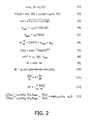
Figure 2 summarizes mathematical expressions relating to the measurement principle; -
Figure 3 is a flow diagram of a typical examination procedure for the determination of the optical absorption coefficient in an object; -
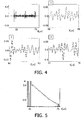
Figure 4 shows an exemplary pulse-echo waveform in an overview (top left) and in three enlarged windows; -
Figure 5 shows the phase-shift in dependence on the depth inside an object determined from the data ofFigure 4 . - Like reference numbers in the Figures refer to identical or similar components.
- When an optical wave propagates through tissue, it gets both attenuated and scattered. Attenuation, scattering and anisotropy define tissue properties within the diffusion approximation of the radiation transport concept, which describes light propagation under strong scattering conditions. The associated absorption and scattering coefficients are illumination wavelength dependent. Typical optical absorption coefficients (OAC) of a biological tissue for wavelengths in visible and near infrared (NIR) is 2-11 cm-1 for muscles, 1-5 cm-1 for blood and around 40 cm-1 for epidermis. The scattering coefficient is around 140 cm-1 for epidermis and 200-500 cm-1 for muscles. The OAC is known to give information not only about the nature of tissues, but also about their pathophysiological state (e.g. hemoglobin oxygen saturation, glucose level (λ = 488 nm)). Furthermore, as the wavelength-dependence of the OAC gives a very specific signature of the chemical components present in a medium, a mapping method to image the OAC of biological media could be of major interest for functional imaging. Moreover, with disease-specific optical agents to be injected in blood that absorb particularly specific wavelengths, the OAC of pathological regions can also have an enhanced contrast with respect to the background OAC by using those compounds, enabling imaging in depth. For these reasons, a reliable and feasible method for the measurement of the OAC in an object is highly desirable.
- When light, particularly laser light, shall be used to investigate the properties of living tissue, safety regulations have to be observed that dictate maximum allowed laser intensity at a given wavelength. A typical limit is 20 mJ/cm2 per pulse (for ultra-short lasers) or 0.2 W/cm2 for continuous wave (CW) at 532 nm laser wavelength, for instance, and it increases in the infrared wavelength regime reaching 40 mJ/cm2 (per pulse) or 0.4 W/cm2 (CW) at 1064 nm. It should however be noted that the safe use of significantly higher intensities (e.g. two orders of magnitude higher) has been demonstrated for certain applications. The aforementioned figures shall therefore not exclude the use of higher intensities in connection with the present invention.
- The aforementioned (allowed) levels of light energy result in a heat deposition of typically a fraction of a Joule per cm3, and a temperature increase of a fraction of one Kelvin to a few Kelvin in an investigated tissue. The heat then gradually diffuses from the laser-absorbing thermal sources to the surrounding tissue. Regarding this light-induced temperature increase, it is known that the speed of sound, v, in biological tissue (with high water content) increases with temperature for temperature rises ΔT on the order of 10-15 K above normal body temperature (37 °C). For small increases from the normal body temperature (ΔT < 10 K), the dependence is nearly linear according to equation (1) of
Figure 2 , where v0 ≈ 1540 m/s is the baseline speed of sound at normal body temperature and αc is in the order of 0.1 % K-1. This acoustical feature has been used to map a temperature increase from a reference baseline using traditional pulse-echo ultrasonic imaging and elastography-inspired signal processing (cf. R. Seip, ES. Ebbini: "Noninvasive estimation of tissue temperature response to heating fields using diagnostic ultrasound", IEEE Transactions on Biomedical Engineering. Vol. 42, no.8, pp. 828-839, 1995). - Based on the above considerations, it is proposed here to use pulse-echo ultrasound (PEU) to image a laser-induced temperature increase, and to infer from that temperature increase the OAC inside an object of interest. Assuming that the relation between a map of temperature increase and the OAC distribution is linear in space and time (the laser intensity being supposed to be uniform), PEU has the potential to reconstruct images of the OAC that can bring much information for diagnostic purposes.
-
Figure 1 shows a principle sketch of an examination apparatus that realizes the proposed approach. The apparatus is used to investigate the optical properties of anobject 1, for example a tissue region under the skin of a patient, wherein an x,y-coordinate system has been drawn for purposes of reference. For simplicity, the following considerations will be limited to a sectional plane through the object, though they may easily be generalized to the three-dimensional case. The examination apparatus comprises the following components: - A
laser light source 10 for illuminating theobject 1 with aheating light beam 11 propagating along the x-direction. - An
ultrasonic scanner 20 that emits ultrasonic pulses along a z-direction that can, in the most general case, be diagonal with respect to the x,y-coordinate system and in particular with respect to the direction of light propagation. TheUS scanner 20 typically comprises an US transducer that first emits an ultrasonic pulse and then records the echoes of this pulse which return from the object after characteristic traveling times (Figure 4 shows an exemplary pulse-echo waveform recorded by such an ultrasonic scanner). - An
evaluation unit 30, for example a workstation, to which theultrasonic scanner 20 and optionally also thelaser light source 10 are coupled. Theevaluation unit 30 comprises several modules 31-34 which may be realized by dedicated hardware or, preferably, by suited routines of a computer program. - A
display unit 40, for example a computer monitor, for showing measurement results like a map of the determined optical absorption coefficient OAC. - In the following, the basic principles of the proposed measurement approach will be explained with reference to the mathematical expressions summarized in
Figure 2 . According to the radiation transport approach, and specifically the diffusion approximation, the intensity I(x, y) of a heating light beam at some depth x within a tissue relates to the incidence intensity I0 at the incidence surface as expressed in equation (2), where it is assumed that the complete spatio-temporal intensity I*(x, y, t) is a product of a spatial and temporal function and wherein a plane wave configuration is assumed for the spatial part. The effective scattering coefficient µeff is defined as in equation (3), wherein µa, µs and g are absorption, scattering and anisotropy coefficients, respectively, which are in equation (2) assumed to be constant. For a real tissue they vary spatially and depend on the light illumination wavelength. - The temporal dependence f(t) of the light illumination can be assumed to be instantaneous if the light pulses are temporally much shorter than the temperature diffusion speed. Another extreme is continuous wave illumination, when the diffusion processes after some transition time stabilize and the configuration is in a steady state.
- Only a part of an incident light beam with intensity I(r) at a position r = (x, y) within the tissue (cf.
Figure 1 ) is absorbed, wherein the absorbed energy density qlaser is proportional to the optical absorption coefficient (OAC) µa. Considering absorption and illumination spectral properties in addition to their spatial distribution, the absorbed energy qlaser is given by equation (4), which is in the following approximated by equation (5). Due to the absorbed energy density qlaser, each absorption centre will behave as a heat source. - The temperature distribution T(r, t) resulting from these heat sources can be derived from the bioheat equation (6), where p is the density, c the specific heat, k the heat conductivity, qlaser the light absorption term and qpm a term that contains effects from perfusion and metabolic activity. For short time scales, the last term qpm does not play an important role and can be neglected. Solving this equation for the case of a single spherical absorbing particle positioned within a non-absorbing tissue gives the temperature distribution of equation (7), assuming that the time t is large enough so that there is an ongoing heat diffusion process.
- For short heating times, smaller than the characteristic diffusion times of tissue (which are on the order of seconds), the heat transfer equation (6) can be simplified to equation (8), in which tlaser represents the time the laser was on and ΔT represents the induced temperature rise. Knowing the values of p and c for the tissue type under consideration (e.g. from F. Duck: "Physical Properties of Tissue: A Comprehensive Reference Work", Elsevier Science & Technology Books), the laser on-time tlaser, the laser intensity I = I(r) at the measuring location r, and the temperature rise ΔT (measured from ultrasonic data), the optical absorption coefficient µa can be obtained from equation (8). In the following, it will therefore be explained how the missing data can be determined, i.e. (i) the temperature rise ΔT and (ii) the laser intensity I(r).
- When a region of tissue is heated, the resulting temperature change ΔT results in variations in the speed of sound. As a result, the backscattered ultrasound echoes (at radio-frequency RF) from the heated region undergo time shifts, and these time shifts can be mapped into apparent displacements u assuming a nominal constant speed v0 of sound throughout the medium (typically 1540 m/s). In the following, it will be assumed that the apparent displacements will only depend on the direction z of propagation of the ultrasound beam, i.e. u = u(z). The time dt that an US pulse needs to travel form a location z to the location z+dz (cf.
Figure 1 ) is described by equation (9). This time dt is interpreted by the US receiver as being caused by a travel of the sound with a constant speed v0 from a shifted location z+u(z) to a shifted location z+u(z)+dz+du, see equation (10). Combining equations (9) and (10) yields equation (11), from which equation (12) can be derived with the help of equation (1). The dimensionless quantity du(z)/dz is referred to as "temperature-induced strain" as it is the spatial gradient of an apparent displacement. This temperature-induced strain is measured from the ultrasound RF backscatter data in a way well-known to persons skilled in the art. Pulse echo speckle measurements can thus be used to obtain a temperature map ΔT(r) of the tissue. - In addition, the pulse echo provides the tissue geometry and structure. The tissue geometry/structure and its temperature rise map ΔT(r) are further sufficient to create an optical absorption and scattering map. To this purpose, the ratio of temperature increases at two nearby locations r A = (xA, yA), r B = (xB, yB) is considered in equation (13), wherein it is assumed that the material coefficients µa, p, c are approximately the same at the two locations (e.g. if r A and r B are chosen from the same type of tissue). Thus the effective scattering coefficient µeff that appears in equation (2) can be derived from the measured temperature increases ΔT(r A), ΔT(r B) and the measured distance(xB-xA). Repeating this procedure for the whole object yields a map µeff(r) of effective scattering coefficients.
- In the next step, the intensity I(r) of a heating light beam that arrives at a location r can be determined by integration of a generalized equation (2) with the help of the now known effective scattering coefficients µeff(r).
- Finally, the OAC µa at location r can be directly calculated from equation (8) as now both ΔT and I(r) are known.
- The described basic steps of the optical absorption mapping procedure can readily be expanded to a multi-layer tissue case by repeating the basic procedure for different transducer positions. An especially simplistic case is when the laser illumination comes from the transducer side (i.e. light propagation is along the pulse-echo line z in
Figure 1 ). Since the pulse-echo provides inherently depth information (and thus separation between the locations r A and r B considered above), it is not required to know the tissue geometry/structure to find OAC tissue map. -
Figure 3 shows the flow diagram of a typical measurement procedure with the examination apparatus ofFigure 1 based on the principles explained above. The procedure starts atstep 101 with an optional injection of a photoactive substance as a contrast agent into the body volume of interest. The contrast agent may particularly be targeting some specific tissue inside a patient. Examples of possible contrast agents are indocyanine green (ICG) and nanoparticles. - In the
next step 102, a first pulse-echo signal is recorded with theultrasonic scanner 20, from which a body structure image can optionally be determined instep 105. - After recording of the first pulse echoes, the object is illuminated with a heating laser light beam of initial intensity I0 for the pulse duration tlaser in
step 103. The heating light beam will induce an associated temperature increase ΔT in the illuminated regions of the object. Immediately after the illumination, a second image of pulse echoes is recorded with theultrasonic scanner 20 instep 104. This image is preferably generated with the same imaging parameters (position of scanner, frequency, viewing angle etc.) as the first pulse-echo image ofstep 102. - The temperature-induced strain du/dz that is found in the second pulse-echo image with respect to the first pulse-echo image is evaluated in
step 106 according to equation (12) to derive the local temperature increases ΔT(r). Thisstep 106 is performed in a "temperature mapping module" 31 of theevaluation unit 30 shown inFigure 1 . - In the
next step 107, the temperature map ΔT(r) and optionally also the structural image obtained atstep 105 is used to determine a map µeff(r) of effective scattering coefficients according to equation (13). Thisstep 107 is performed in a "scatter mapping module" 32 of theevaluation unit 30. - Based on the map µeff(r) of effective scattering coefficients, the light intensity distribution I(r) throughout the object can be determined in
step 108 based on the given initial light intensity I0 and the direction of the heating light beam according to equation (2). Thisstep 108 is performed in an "intensity mapping module" 33 of theevaluation unit 30. - In a
final step 109, the desired map µa(r) of the OAC is determined with the help of equation (8) from the intensity I(r) and the temperature increase ΔT(r) previously obtained. This step is performed in an "OAC mapping module" 34 of theevaluation unit 30. Additionally or alternatively to the OAC, other optical coefficients like the scattering coefficient µs could be determined as well. - In summary, the described method for acquiring optical absorption coefficients from ultrasonic pulse-echo images comprises the following basic steps:
- 1) An ultrasonic pulse-echo image is acquired before and shortly after the light illumination exposure, wherein one pulse-echo line before and after illumination can be sufficient for obtaining the OACs along the line.
- 2) The temperature change is identified in at least two spatially separated points which belong to a tissue section sharing the same OAC.
- 3) The optical absorption coefficient is obtained from the temperature change ratio between the aforementioned points and their separation, combined with at least one of the temperature changes and its depth information. The minimum required separation of the relevant points is only determined by the temperature acquiring process resolution.
-
Figure 4 shows exemplary pulse-echo waveforms obtained from an ink doped agar gel phantom of block-shape immersed into water (vertical axis: relative units; horizontal axis: pulse traveling time t). The ink was uniformly dispersed during the phantom fabrication process. Pulsed, nanosecond Nd:YAG, laser was shined from a side of the phantom, providing uniform illumination along the ultrasonic pulse-echo acquisition line as the US transducer was aligned along an edge of the phantom perpendicular to the light direction (corresponding to an axis z perpendicular to the x-axis inFigure 1 ). In the shown captured echo from the phantom (top left diagram), two signals - before and after laser illumination - are strongly overlapped and can be resolved only after zooming-in as shown in thegraphs graphs windows 2 and 3). The laser illumination is uniform along the phantom surface, resulting in a uniform temperature change. Therefore the phase shift increases/decreases linearly.Figure 5 shows in this respect a nearly linear drop in phase shift Φ (vertical axis) along the length of the phantom (horizontal axis, measured by the pulse traveling time t). Using equation (12), this corresponds to a 2 K temperature increase (assuming αc = 0.001 for the phantom) in the phantom following application of the laser pulse. The slope of the curve, dΦ/dt = -αcω0ΔT (with ω0 = 2π· 10 MHz), indicates a temperature rise in the phantom on the order of 1.7 K for a heated zone of 2 cm. - Finally it is pointed out that in the present application the term "comprising" does not exclude other elements or steps, that "a" or "an" does not exclude a plurality, and that a single processor or other unit may fulfill the functions of several means. The invention resides in each and every novel characteristic feature and each and every combination of characteristic features. Moreover, reference signs in the claims shall not be construed as limiting their scope.
Claims (8)
- An examination apparatus for the determination of an optical coefficient (µa) at at least one measuring location (r) in an object (1), comprising- a light source (10) for selectively sending a heating light beam (11) to the measuring location;- an ultrasonic scanner (20) for measuring the pulse echoes of ultrasonic pulses sent to the measuring location;- an evaluation unit (30) for determining the optical coefficient (µa) at the measuring location from pulse echoes that were measured before and after sending a heating light beam to the measuring location,wherein said evaluation unit (30) comprises:a) a temperature mapping module (31) for determining a spatial map of the temperature increase (ΔT(r)) induced in the object (1) by the heating light beam (11);b) a scatter mapping module (32) for estimating a spatial map of the effective optical scattering properties (µeff(r)) in the object (1);c) an intensity estimation module (33) for determining the light intensity (I(r)) of the heating light beam (11) at the measuring location.
- The examination apparatus according to claim 1,
characterized in that the optical coefficient comprises the optical absorption coefficient (µa) and/or the optical scattering coefficient (µs). - The examination apparatus according to claim 1,
characterized in that the heating light beam (11) comprises only light of a given spectral composition. - The examination apparatus according to claim 1,
characterized in that the light source (10) and the ultrasonic scanner (20) have parallel radiation directions. - The examination apparatus according to claim 1,
characterized in that it comprises an injection device for injecting a contrast agent with specific light absorbing properties into the object (1). - A method for the determination of an optical coefficient (µa) at at least one measuring location (r) in an object (1), comprising- measuring first pulse echoes of ultrasonic pulses sent to the measuring location;- sending a heating light beam (11) to the measuring location;- measuring second pulse echoes of ultrasonic pulses sent to the measuring location;- determining the optical coefficient from the first and second pulse echoes, wherein- a map of the temperature increase (ΔT(r)) inside the object (1) is determined from the first and second pulse echoes;- a spatial map of the effective optical scattering properties (µeff(r)) in the object (1) is estimated;- the intensity (I(r)) of the heating light beam (11) at the measuring location (r) is determined from the map of temperature increase (ΔT(r)).
- The method according to claim 6,
characterized in that the optical coefficient is determined at a plurality of locations inside the object (1). - A record carrier on which a computer program for the determination of an optical coefficient (µa) at at least one measuring location (r) in an object (1) is stored, said program being adapted to execute a method according to claim 6.
Priority Applications (1)
| Application Number | Priority Date | Filing Date | Title |
|---|---|---|---|
| EP07826422A EP2074418B1 (en) | 2006-09-29 | 2007-09-18 | Ultrasonic determination of optical absorption coefficients |
Applications Claiming Priority (3)
| Application Number | Priority Date | Filing Date | Title |
|---|---|---|---|
| EP06121524 | 2006-09-29 | ||
| PCT/IB2007/053763 WO2008038182A2 (en) | 2006-09-29 | 2007-09-18 | Ultrasonic determination of optical absorption coefficients |
| EP07826422A EP2074418B1 (en) | 2006-09-29 | 2007-09-18 | Ultrasonic determination of optical absorption coefficients |
Publications (2)
| Publication Number | Publication Date |
|---|---|
| EP2074418A2 EP2074418A2 (en) | 2009-07-01 |
| EP2074418B1 true EP2074418B1 (en) | 2013-03-06 |
Family
ID=39145029
Family Applications (1)
| Application Number | Title | Priority Date | Filing Date |
|---|---|---|---|
| EP07826422A Not-in-force EP2074418B1 (en) | 2006-09-29 | 2007-09-18 | Ultrasonic determination of optical absorption coefficients |
Country Status (7)
| Country | Link |
|---|---|
| US (1) | US8328721B2 (en) |
| EP (1) | EP2074418B1 (en) |
| JP (1) | JP5379005B2 (en) |
| CN (1) | CN101523203B (en) |
| BR (1) | BRPI0717548A2 (en) |
| RU (1) | RU2437089C2 (en) |
| WO (1) | WO2008038182A2 (en) |
Families Citing this family (14)
| Publication number | Priority date | Publication date | Assignee | Title |
|---|---|---|---|---|
| JP4279328B2 (en) * | 2007-05-07 | 2009-06-17 | 株式会社日立製作所 | Ultrasound imaging system |
| US8870772B2 (en) | 2008-12-29 | 2014-10-28 | Perseus-Biomed Inc. | Method and system for tissue recognition |
| US8882672B2 (en) | 2008-12-29 | 2014-11-11 | Perseus-Biomed Inc. | Method and system for tissue imaging and analysis |
| US8864669B2 (en) | 2008-12-29 | 2014-10-21 | Perseus-Biomed Inc. | Method and system for tissue imaging and analysis |
| JP5648957B2 (en) * | 2010-10-22 | 2015-01-07 | 浜松ホトニクス株式会社 | Breast measuring device |
| US20150250388A1 (en) * | 2013-07-10 | 2015-09-10 | The Board Of Trustees Of The Leland Stanford Junior University | Remote sensing, imaging, or screening of embedded or concealed objects |
| DE102014107261A1 (en) * | 2014-05-22 | 2015-11-26 | Nirlus Engineering Ag | Method for the noninvasive optical measurement of properties of flowing blood |
| WO2015177658A1 (en) | 2014-05-23 | 2015-11-26 | Koninklijke Philips N.V. | Motion gated-ultrasound thermometry using adaptive frame selection. |
| JP6512969B2 (en) * | 2015-07-06 | 2019-05-15 | キヤノン株式会社 | PROCESSING APPARATUS, PHOTOACOUSTIC APPARATUS, PROCESSING METHOD, AND PROGRAM |
| US9987089B2 (en) | 2015-07-13 | 2018-06-05 | University of Central Oklahoma | Device and a method for imaging-guided photothermal laser therapy for cancer treatment |
| KR101734984B1 (en) * | 2015-12-10 | 2017-05-12 | 한밭대학교 산학협력단 | Method for estimating optical absorption coefficient at frequency domain by using photoacoustic detector |
| US20230024917A1 (en) * | 2021-07-19 | 2023-01-26 | Cardiac Pacemakers, Inc. | Devices and methods for deep tissue temperature measurement using optical sensing |
| US12446782B2 (en) | 2021-07-19 | 2025-10-21 | Cardiac Pacemakers, Inc. | Devices and methods for assessing pulmonary congestion using optical sensing |
| US12599321B2 (en) | 2021-07-19 | 2026-04-14 | Cardiac Pacemakers, Inc. | Devices and methods for assessing pulmonary status using optical oxygenation sensing |
Family Cites Families (18)
| Publication number | Priority date | Publication date | Assignee | Title |
|---|---|---|---|---|
| JPS60199429A (en) * | 1984-03-24 | 1985-10-08 | アロカ株式会社 | In vivo temperature measuring apparatus |
| JPH03258251A (en) * | 1990-03-09 | 1991-11-18 | Gijutsu Kenkyu Kumiai Iryo Fukushi Kiki Kenkyusho | Apparatus for measuring temperature distribution |
| US6405069B1 (en) * | 1996-01-31 | 2002-06-11 | Board Of Regents, The University Of Texas System | Time-resolved optoacoustic method and system for noninvasive monitoring of glucose |
| RU2184486C2 (en) * | 1996-08-06 | 2002-07-10 | Техноцентр "Лазерная диагностика и чистые технологии" | Method and device for diagnosing oncological diseases |
| RU2168927C2 (en) * | 1997-02-07 | 2001-06-20 | Гриф Алексей Вадимович | Method for building images of cavities filled with blood |
| WO2001010295A1 (en) * | 1999-08-06 | 2001-02-15 | The Board Of Regents Of The University Of Texas System | Optoacoustic monitoring of blood oxygenation |
| JP2001145628A (en) * | 1999-11-19 | 2001-05-29 | Aloka Co Ltd | Sound wave measuring instrument |
| IL138073A0 (en) * | 2000-08-24 | 2001-10-31 | Glucon Inc | Photoacoustic assay and imaging system |
| MXPA03006726A (en) * | 2001-01-26 | 2004-10-15 | Sensys Medical Inc | NON-INVASIVE MEASUREMENT OF GLUCOSE THROUGH THE OPTICAL PROPERTIES OF THE FABRICS. |
| US7179449B2 (en) * | 2001-01-30 | 2007-02-20 | Barnes-Jewish Hospital | Enhanced ultrasound detection with temperature-dependent contrast agents |
| US20050085725A1 (en) * | 2001-08-09 | 2005-04-21 | Ron Nagar | Photoacoustic assay and imaging system |
| US6692438B2 (en) * | 2001-12-18 | 2004-02-17 | Koninklijke Philips Electronics Nv | Ultrasonic imaging system and method for displaying tissue perfusion and other parameters varying with time |
| WO2004086965A1 (en) | 2003-04-01 | 2004-10-14 | Glucon Inc. | Photoacoustic assay method and apparatus |
| US7740585B2 (en) * | 2006-01-20 | 2010-06-22 | Seno Medical Instruments, Inc. | Quantitative optoacoustic tomography with enhanced contrast |
| JP4820239B2 (en) * | 2006-08-28 | 2011-11-24 | 公立大学法人大阪府立大学 | Probe for optical tomography equipment |
| JP4909132B2 (en) * | 2006-08-28 | 2012-04-04 | 公立大学法人大阪府立大学 | Optical tomography equipment |
| US8108030B2 (en) * | 2006-10-20 | 2012-01-31 | Board Of Regents, The University Of Texas System | Method and apparatus to identify vulnerable plaques with thermal wave imaging of heated nanoparticles |
| WO2009045885A2 (en) * | 2007-10-02 | 2009-04-09 | Board Of Regents, The University Of Texas System | Real-time ultrasound monitoring of heat-induced tissue interactions |
-
2007
- 2007-09-18 JP JP2009529810A patent/JP5379005B2/en not_active Expired - Fee Related
- 2007-09-18 EP EP07826422A patent/EP2074418B1/en not_active Not-in-force
- 2007-09-18 BR BRPI0717548-5A patent/BRPI0717548A2/en not_active Application Discontinuation
- 2007-09-18 CN CN2007800364557A patent/CN101523203B/en not_active Expired - Fee Related
- 2007-09-18 WO PCT/IB2007/053763 patent/WO2008038182A2/en not_active Ceased
- 2007-09-18 RU RU2009116237/28A patent/RU2437089C2/en not_active IP Right Cessation
- 2007-09-18 US US12/442,729 patent/US8328721B2/en not_active Expired - Fee Related
Also Published As
| Publication number | Publication date |
|---|---|
| US8328721B2 (en) | 2012-12-11 |
| RU2009116237A (en) | 2010-11-10 |
| WO2008038182A3 (en) | 2008-06-05 |
| US20100043557A1 (en) | 2010-02-25 |
| CN101523203B (en) | 2012-09-05 |
| CN101523203A (en) | 2009-09-02 |
| EP2074418A2 (en) | 2009-07-01 |
| BRPI0717548A2 (en) | 2013-10-22 |
| RU2437089C2 (en) | 2011-12-20 |
| WO2008038182A2 (en) | 2008-04-03 |
| JP5379005B2 (en) | 2013-12-25 |
| JP2010504791A (en) | 2010-02-18 |
Similar Documents
| Publication | Publication Date | Title |
|---|---|---|
| US8328721B2 (en) | Ultrasonic determination of optical absorption coefficients | |
| US12408839B2 (en) | Transcranial photoacoustic/thermoacoustic tomography brain imaging informed by adjunct image data | |
| US8364414B2 (en) | Apparatus and method for processing biological information | |
| US9220415B2 (en) | Systems and methods for frequency-domain photoacoustic phased array imaging | |
| EP0920277B1 (en) | Laser opto-acoustic imaging system | |
| Wang | Ultrasound‐mediated biophotonic imaging: A review of acousto‐optical tomography and photo‐acoustic tomography | |
| EP2553425B1 (en) | Photoacoustic imaging apparatus and photoacoustic imaging method | |
| CN101677765B (en) | Bioinformatics imaging device and method, bioinformatics analysis method | |
| Elson et al. | Ultrasound-mediated optical tomography: a review of current methods | |
| US20100087733A1 (en) | Biological information processing apparatus and biological information processing method | |
| JP2009018153A (en) | Biological information imaging device | |
| US20160051149A1 (en) | Photoacoustic Probe for Burn Injury Diagnosis | |
| JP2011217914A (en) | Photoacoustic imaging apparatus, photoacoustic imaging method, and program | |
| Fincke et al. | Characterization of laser ultrasound source signals in biological tissues for imaging applications | |
| US20080234567A1 (en) | Apparatus and method for providing a noninvasive diagnosis of internal bleeding | |
| JP2013055988A (en) | Apparatus and method for acquiring subject information | |
| JP5709852B2 (en) | Apparatus and method for photon absorption coefficient measurement | |
| Salih et al. | [Retracted] Evaluation of Cholesterol Thickness of Blood Vessels Using Photoacoustic Technology | |
| JP2017100032A (en) | Subject information acquisition device and subject information acquisition method | |
| Haupt et al. | Noncontact laser ultrasound for biomedical imaging applications | |
| Haupt et al. | Non-Contact Optical Ultrasound Concept for Biomedical Imaging | |
| Fieramonti | Feasibility, development and characterization of a photoacoustic microscopy system for biomedical applications | |
| Zainal | A Laser Photoacoustic Probe: Characterisation and Its Application for Tissue Recognition | |
| Maslov et al. | Photoacoustic microscopy of cerebral blood-oxygenation dynamics in mice | |
| JP2016104230A (en) | Subject information acquisition device and subject information acquisition method |
Legal Events
| Date | Code | Title | Description |
|---|---|---|---|
| PUAI | Public reference made under article 153(3) epc to a published international application that has entered the european phase |
Free format text: ORIGINAL CODE: 0009012 |
|
| 17P | Request for examination filed |
Effective date: 20090429 |
|
| AK | Designated contracting states |
Kind code of ref document: A2 Designated state(s): AT BE BG CH CY CZ DE DK EE ES FI FR GB GR HU IE IS IT LI LT LU LV MC MT NL PL PT RO SE SI SK TR |
|
| AX | Request for extension of the european patent |
Extension state: AL BA HR MK RS |
|
| 17Q | First examination report despatched |
Effective date: 20090721 |
|
| DAX | Request for extension of the european patent (deleted) | ||
| GRAP | Despatch of communication of intention to grant a patent |
Free format text: ORIGINAL CODE: EPIDOSNIGR1 |
|
| GRAS | Grant fee paid |
Free format text: ORIGINAL CODE: EPIDOSNIGR3 |
|
| GRAA | (expected) grant |
Free format text: ORIGINAL CODE: 0009210 |
|
| AK | Designated contracting states |
Kind code of ref document: B1 Designated state(s): AT BE BG CH CY CZ DE DK EE ES FI FR GB GR HU IE IS IT LI LT LU LV MC MT NL PL PT RO SE SI SK TR |
|
| REG | Reference to a national code |
Ref country code: GB Ref legal event code: FG4D |
|
| REG | Reference to a national code |
Ref country code: CH Ref legal event code: EP Ref country code: AT Ref legal event code: REF Ref document number: 599903 Country of ref document: AT Kind code of ref document: T Effective date: 20130315 |
|
| REG | Reference to a national code |
Ref country code: IE Ref legal event code: FG4D |
|
| REG | Reference to a national code |
Ref country code: DE Ref legal event code: R096 Ref document number: 602007028932 Country of ref document: DE Effective date: 20130502 |
|
| RAP2 | Party data changed (patent owner data changed or rights of a patent transferred) |
Owner name: KONINKLIJKE PHILIPS N.V. |
|
| REG | Reference to a national code |
Ref country code: AT Ref legal event code: MK05 Ref document number: 599903 Country of ref document: AT Kind code of ref document: T Effective date: 20130306 Ref country code: CH Ref legal event code: PFA Owner name: KONINKLIJKE PHILIPS N.V., NL Free format text: FORMER OWNER: KONINKLIJKE PHILIPS ELECTRONICS N.V., NL |
|
| PG25 | Lapsed in a contracting state [announced via postgrant information from national office to epo] |
Ref country code: BG Free format text: LAPSE BECAUSE OF FAILURE TO SUBMIT A TRANSLATION OF THE DESCRIPTION OR TO PAY THE FEE WITHIN THE PRESCRIBED TIME-LIMIT Effective date: 20130606 Ref country code: AT Free format text: LAPSE BECAUSE OF FAILURE TO SUBMIT A TRANSLATION OF THE DESCRIPTION OR TO PAY THE FEE WITHIN THE PRESCRIBED TIME-LIMIT Effective date: 20130306 Ref country code: LT Free format text: LAPSE BECAUSE OF FAILURE TO SUBMIT A TRANSLATION OF THE DESCRIPTION OR TO PAY THE FEE WITHIN THE PRESCRIBED TIME-LIMIT Effective date: 20130306 Ref country code: SE Free format text: LAPSE BECAUSE OF FAILURE TO SUBMIT A TRANSLATION OF THE DESCRIPTION OR TO PAY THE FEE WITHIN THE PRESCRIBED TIME-LIMIT Effective date: 20130306 Ref country code: ES Free format text: LAPSE BECAUSE OF FAILURE TO SUBMIT A TRANSLATION OF THE DESCRIPTION OR TO PAY THE FEE WITHIN THE PRESCRIBED TIME-LIMIT Effective date: 20130617 |
|
| REG | Reference to a national code |
Ref country code: NL Ref legal event code: VDEP Effective date: 20130306 |
|
| REG | Reference to a national code |
Ref country code: LT Ref legal event code: MG4D |
|
| PG25 | Lapsed in a contracting state [announced via postgrant information from national office to epo] |
Ref country code: GR Free format text: LAPSE BECAUSE OF FAILURE TO SUBMIT A TRANSLATION OF THE DESCRIPTION OR TO PAY THE FEE WITHIN THE PRESCRIBED TIME-LIMIT Effective date: 20130607 Ref country code: SI Free format text: LAPSE BECAUSE OF FAILURE TO SUBMIT A TRANSLATION OF THE DESCRIPTION OR TO PAY THE FEE WITHIN THE PRESCRIBED TIME-LIMIT Effective date: 20130306 Ref country code: FI Free format text: LAPSE BECAUSE OF FAILURE TO SUBMIT A TRANSLATION OF THE DESCRIPTION OR TO PAY THE FEE WITHIN THE PRESCRIBED TIME-LIMIT Effective date: 20130306 Ref country code: LV Free format text: LAPSE BECAUSE OF FAILURE TO SUBMIT A TRANSLATION OF THE DESCRIPTION OR TO PAY THE FEE WITHIN THE PRESCRIBED TIME-LIMIT Effective date: 20130306 |
|
| PG25 | Lapsed in a contracting state [announced via postgrant information from national office to epo] |
Ref country code: BE Free format text: LAPSE BECAUSE OF FAILURE TO SUBMIT A TRANSLATION OF THE DESCRIPTION OR TO PAY THE FEE WITHIN THE PRESCRIBED TIME-LIMIT Effective date: 20130306 |
|
| PG25 | Lapsed in a contracting state [announced via postgrant information from national office to epo] |
Ref country code: PT Free format text: LAPSE BECAUSE OF FAILURE TO SUBMIT A TRANSLATION OF THE DESCRIPTION OR TO PAY THE FEE WITHIN THE PRESCRIBED TIME-LIMIT Effective date: 20130708 Ref country code: IS Free format text: LAPSE BECAUSE OF FAILURE TO SUBMIT A TRANSLATION OF THE DESCRIPTION OR TO PAY THE FEE WITHIN THE PRESCRIBED TIME-LIMIT Effective date: 20130706 Ref country code: SK Free format text: LAPSE BECAUSE OF FAILURE TO SUBMIT A TRANSLATION OF THE DESCRIPTION OR TO PAY THE FEE WITHIN THE PRESCRIBED TIME-LIMIT Effective date: 20130306 Ref country code: CZ Free format text: LAPSE BECAUSE OF FAILURE TO SUBMIT A TRANSLATION OF THE DESCRIPTION OR TO PAY THE FEE WITHIN THE PRESCRIBED TIME-LIMIT Effective date: 20130306 Ref country code: RO Free format text: LAPSE BECAUSE OF FAILURE TO SUBMIT A TRANSLATION OF THE DESCRIPTION OR TO PAY THE FEE WITHIN THE PRESCRIBED TIME-LIMIT Effective date: 20130306 Ref country code: NL Free format text: LAPSE BECAUSE OF FAILURE TO SUBMIT A TRANSLATION OF THE DESCRIPTION OR TO PAY THE FEE WITHIN THE PRESCRIBED TIME-LIMIT Effective date: 20130306 Ref country code: EE Free format text: LAPSE BECAUSE OF FAILURE TO SUBMIT A TRANSLATION OF THE DESCRIPTION OR TO PAY THE FEE WITHIN THE PRESCRIBED TIME-LIMIT Effective date: 20130306 |
|
| PG25 | Lapsed in a contracting state [announced via postgrant information from national office to epo] |
Ref country code: CY Free format text: LAPSE BECAUSE OF FAILURE TO SUBMIT A TRANSLATION OF THE DESCRIPTION OR TO PAY THE FEE WITHIN THE PRESCRIBED TIME-LIMIT Effective date: 20130306 Ref country code: PL Free format text: LAPSE BECAUSE OF FAILURE TO SUBMIT A TRANSLATION OF THE DESCRIPTION OR TO PAY THE FEE WITHIN THE PRESCRIBED TIME-LIMIT Effective date: 20130306 |
|
| PLBE | No opposition filed within time limit |
Free format text: ORIGINAL CODE: 0009261 |
|
| STAA | Information on the status of an ep patent application or granted ep patent |
Free format text: STATUS: NO OPPOSITION FILED WITHIN TIME LIMIT |
|
| PG25 | Lapsed in a contracting state [announced via postgrant information from national office to epo] |
Ref country code: DK Free format text: LAPSE BECAUSE OF FAILURE TO SUBMIT A TRANSLATION OF THE DESCRIPTION OR TO PAY THE FEE WITHIN THE PRESCRIBED TIME-LIMIT Effective date: 20130306 |
|
| 26N | No opposition filed |
Effective date: 20131209 |
|
| PG25 | Lapsed in a contracting state [announced via postgrant information from national office to epo] |
Ref country code: IT Free format text: LAPSE BECAUSE OF FAILURE TO SUBMIT A TRANSLATION OF THE DESCRIPTION OR TO PAY THE FEE WITHIN THE PRESCRIBED TIME-LIMIT Effective date: 20130306 |
|
| REG | Reference to a national code |
Ref country code: DE Ref legal event code: R097 Ref document number: 602007028932 Country of ref document: DE Effective date: 20131209 |
|
| REG | Reference to a national code |
Ref country code: DE Ref legal event code: R082 Ref document number: 602007028932 Country of ref document: DE Representative=s name: MEISSNER, BOLTE & PARTNER GBR, DE |
|
| PG25 | Lapsed in a contracting state [announced via postgrant information from national office to epo] |
Ref country code: MC Free format text: LAPSE BECAUSE OF FAILURE TO SUBMIT A TRANSLATION OF THE DESCRIPTION OR TO PAY THE FEE WITHIN THE PRESCRIBED TIME-LIMIT Effective date: 20130306 |
|
| REG | Reference to a national code |
Ref country code: CH Ref legal event code: PL |
|
| REG | Reference to a national code |
Ref country code: DE Ref legal event code: R082 Ref document number: 602007028932 Country of ref document: DE Representative=s name: MEISSNER BOLTE PATENTANWAELTE RECHTSANWAELTE P, DE Effective date: 20140331 Ref country code: DE Ref legal event code: R081 Ref document number: 602007028932 Country of ref document: DE Owner name: KONINKLIJKE PHILIPS N.V., NL Free format text: FORMER OWNER: KONINKLIJKE PHILIPS ELECTRONICS N.V., EINDHOVEN, NL Effective date: 20140331 Ref country code: DE Ref legal event code: R082 Ref document number: 602007028932 Country of ref document: DE Representative=s name: MEISSNER, BOLTE & PARTNER GBR, DE Effective date: 20140331 |
|
| GBPC | Gb: european patent ceased through non-payment of renewal fee |
Effective date: 20130918 |
|
| REG | Reference to a national code |
Ref country code: IE Ref legal event code: MM4A |
|
| PG25 | Lapsed in a contracting state [announced via postgrant information from national office to epo] |
Ref country code: GB Free format text: LAPSE BECAUSE OF NON-PAYMENT OF DUE FEES Effective date: 20130918 Ref country code: LI Free format text: LAPSE BECAUSE OF NON-PAYMENT OF DUE FEES Effective date: 20130930 Ref country code: IE Free format text: LAPSE BECAUSE OF NON-PAYMENT OF DUE FEES Effective date: 20130918 Ref country code: CH Free format text: LAPSE BECAUSE OF NON-PAYMENT OF DUE FEES Effective date: 20130930 |
|
| PG25 | Lapsed in a contracting state [announced via postgrant information from national office to epo] |
Ref country code: MT Free format text: LAPSE BECAUSE OF FAILURE TO SUBMIT A TRANSLATION OF THE DESCRIPTION OR TO PAY THE FEE WITHIN THE PRESCRIBED TIME-LIMIT Effective date: 20130306 |
|
| PG25 | Lapsed in a contracting state [announced via postgrant information from national office to epo] |
Ref country code: LU Free format text: LAPSE BECAUSE OF NON-PAYMENT OF DUE FEES Effective date: 20130918 Ref country code: HU Free format text: LAPSE BECAUSE OF FAILURE TO SUBMIT A TRANSLATION OF THE DESCRIPTION OR TO PAY THE FEE WITHIN THE PRESCRIBED TIME-LIMIT; INVALID AB INITIO Effective date: 20070918 |
|
| REG | Reference to a national code |
Ref country code: FR Ref legal event code: PLFP Year of fee payment: 9 |
|
| REG | Reference to a national code |
Ref country code: FR Ref legal event code: PLFP Year of fee payment: 10 |
|
| REG | Reference to a national code |
Ref country code: FR Ref legal event code: PLFP Year of fee payment: 11 |
|
| PGFP | Annual fee paid to national office [announced via postgrant information from national office to epo] |
Ref country code: TR Payment date: 20170907 Year of fee payment: 11 |
|
| PGFP | Annual fee paid to national office [announced via postgrant information from national office to epo] |
Ref country code: FR Payment date: 20171002 Year of fee payment: 11 Ref country code: DE Payment date: 20171130 Year of fee payment: 11 |
|
| REG | Reference to a national code |
Ref country code: DE Ref legal event code: R119 Ref document number: 602007028932 Country of ref document: DE |
|
| PG25 | Lapsed in a contracting state [announced via postgrant information from national office to epo] |
Ref country code: DE Free format text: LAPSE BECAUSE OF NON-PAYMENT OF DUE FEES Effective date: 20190402 |
|
| PG25 | Lapsed in a contracting state [announced via postgrant information from national office to epo] |
Ref country code: FR Free format text: LAPSE BECAUSE OF NON-PAYMENT OF DUE FEES Effective date: 20180930 |
|
| PG25 | Lapsed in a contracting state [announced via postgrant information from national office to epo] |
Ref country code: TR Free format text: LAPSE BECAUSE OF NON-PAYMENT OF DUE FEES Effective date: 20180918 |