EP2074398B1 - Multi-channel manometer with independent fluid level adjustments - Google Patents
Multi-channel manometer with independent fluid level adjustments Download PDFInfo
- Publication number
- EP2074398B1 EP2074398B1 EP07853975.6A EP07853975A EP2074398B1 EP 2074398 B1 EP2074398 B1 EP 2074398B1 EP 07853975 A EP07853975 A EP 07853975A EP 2074398 B1 EP2074398 B1 EP 2074398B1
- Authority
- EP
- European Patent Office
- Prior art keywords
- manometer
- channels
- channel
- pressure
- carburetors
- Prior art date
- Legal status (The legal status is an assumption and is not a legal conclusion. Google has not performed a legal analysis and makes no representation as to the accuracy of the status listed.)
- Active
Links
Images



Classifications
-
- G—PHYSICS
- G01—MEASURING; TESTING
- G01L—MEASURING FORCE, STRESS, TORQUE, WORK, MECHANICAL POWER, MECHANICAL EFFICIENCY, OR FLUID PRESSURE
- G01L7/00—Measuring the steady or quasi-steady pressure of a fluid or a fluent solid material by mechanical or fluid pressure-sensitive elements
- G01L7/18—Measuring the steady or quasi-steady pressure of a fluid or a fluent solid material by mechanical or fluid pressure-sensitive elements using liquid as the pressure-sensitive medium, e.g. liquid-column gauges
- G01L7/182—Measuring the steady or quasi-steady pressure of a fluid or a fluent solid material by mechanical or fluid pressure-sensitive elements using liquid as the pressure-sensitive medium, e.g. liquid-column gauges constructional details, e.g. mounting
-
- G—PHYSICS
- G01—MEASURING; TESTING
- G01M—TESTING STATIC OR DYNAMIC BALANCE OF MACHINES OR STRUCTURES; TESTING OF STRUCTURES OR APPARATUS, NOT OTHERWISE PROVIDED FOR
- G01M15/00—Testing of engines
Definitions
- the present invention relates generally to devices for measurement of pressure and more particularly to manometers for synchronization of engine carburetors.
- the carburetor is a device that mixes air and fuel for an internal combustion engine.
- the majority of motorcycles and many snowmobiles and outboard motors still are carbureted due to lower weight and cost compared to fuel-injected engines.
- Some carbureted engines have a single carburetor, though the modem trend is to use multiple carburetors, of two to eight carburetors.
- the carburetor works on Bernoulli's principle, which is that moving air has lower pressure than still air, and that the faster the movement of the air, the lower the pressure.
- the throttle or accelerator controls the amount of air that flows through the carburetor. Faster flows of air entering the carburetor draws more fuel into the carburetor due to the partial vacuum that is created.
- most carburetors require tuning, and for engines with multiple carburetors, it is important that the carburetors be tuned together to provide balanced performance.
- a manometer is a pressure measuring instrument which is typically used when adjusting carburetors, whether single or multiple. It uses a column of liquid whose height in a glass tube indicates the pressure which is applied to the openings of the tube.
- Manometers can be of the type referred to as an "open-end manometer" which is generally "U-shaped" and has both ends open. One of the open ends is typically open to atmospheric pressure and the other end is then connected to a pressure source to be measured. By comparing the levels in the two legs of the U structure, the pressure of the pressure source can be measured compared to atmospheric pressure.
- the second type of manometer in common use is referred to as a "closed-end manometer" where one end is closed and thus a vacuum source connected to the open end pulls against the liquid in the closed tube. This generally gives a measurement of pressure which is lower than atmospheric pressure.
- the goal is generally to have the air flow (and thus pressure) in each of the carburettors match as closely as possible to each other. Since it is the relative pressure in each carburettor with respect to each other that is important, the absolute pressure in each channel is not usually as concern. Thus, the purpose of using a manometer for pressure measurement is generally to equalize the pressure in all of the carburetors.
- US 3,315,527 A and US 3,921,454 A disclose manometers having a plurality of channels.
- US 4,683,756 discloses a manometer including a reservoir portion and an adjustment mechanism.
- Another object of the invention is to provide a manometer with multiple channels.
- Yet another object of the invention is to provide a manometer with multiple channels which each have a fluid-level adjustment.
- a further object of the present invention is to provide multiple manometer channels which can be adjusted in relation to each other independently.
- An additional object of the present invention is to provide a manometer which does not use mercury as a level indicator fluid.
- Yet another object of the present invention is to provide a tool in which multiple manometers are grouped together in a single device.
- Another object of the present invention is to provide a manometer with multiple channels that can be used independently.
- the tool can be used as a 1, 2, 3, or 4 channel manometer.
- one preferred embodiment of the present invention is a manometer for multi-channel pressure measurement which includes two or more manometer channels, where each channel includes an independent fluid level adjustment. Also included is a method for calibrating multiple carburetors using a manometer having multiple channels, each having an independent fluid level adjustment.
- An advantage of the present invention is that multiple carburetors on the same or separate vehicle can be adjusted simultaneously.
- Another advantage of the present invention is that multiple pressure-measuring devices are grouped in a single device so that they may be easily compared side-by-side.
- each of the multiple channels is independently adjustable to set a reference-line for each, or to set a common reference-line used by all channels.
- a further advantage of the present invention is that adjustment screws for each channel are grouped in a configuration that is easily accessible for manipulation.
- a yet further advantage is that the multiple manometer channels are grouped in a freestanding housing that provides a stable base of support for the manometers.
- Another advantage of the present invention is the free standing housing provides reference marks so the user can clearly see when the fluid-levels of the multiple channels are aligned.
- each channel is independent of the other channels allowing the user to use as few or as many of the channels as they need.
- a further advantage of the present invention is that the manometer does not have to be kept in the upright position while being used or stored to prevent the level indicator fluid from running out of the reservoirs.
- the present invention is an adjustable multi-channel manometer, which will be referred to by the reference number 10, and thus, for simplicity, shall be referred to as manometer 10.
- a first preferred embodiment of the manometer 10 is illustrated in Figs. 1-5 , of which Fig. 1 is a perspective view, Fig. 2 is a side plan view, and Fig. 3 is a front plan view.
- the manometer 10 includes a housing 12 having a front face 14 which includes a slanted panel 16.
- the housing 12 is preferably, but not necessarily, translucent or transparent, so the fluid levels in the housing 12 may be observed.
- a number of manometer tubes 18 are grouped in the housing 12, and each manometer tube 18 includes a column of manometer fluid 20.
- the tubes 18 and fluid 20 are included in each of the manometer channels 22, along with other elements which will be discussed below.
- the slanted panel 16 includes a number of adjustment screws 24, of which there is one for each of the manometer channels 22. These adjustment screws 24 are important for setting the reference line 5 in each channel 22, as will be discussed below.
- manometer channels 22 are shown in the embodiment of Fig. 1 . These shall be referred to as channel #1 26 , channel #2 28, channel #3 30 and channel #4 32. It shall be understood by those skilled in the art that the number of channels is not restricted to four. There could be as few as two channels, and the number of channels could be eight or more, depending on the number of devices which are intended to be calibrated.
- the multi-channel manometer 10 could be used to tune two carburetors on a vehicle, or could be used to tune eight carburetors on 8 vehicles, etc. Thus, the numbers of channels shown in the illustrations are not to be construed as limitations.
- Fig. 1 also shows four carburetors, designated as carburetor #1, designated element 1, carburetor #2 2 , carburetor #3 3, and carburetor #4 4.
- Carburetor #1 1 is shown to be connected to manometer channel #1 26 by a vacuum line 6, and the other carburetors 2, 3, 4 are shown to be connected to channels 28, 30, 32 respectively in a similar manner.
- Each carburetor 1, 2, 3, 4 includes its own adjustment mechanism 7 which controls the air flow in the carburetor in order to tune its performance.
- the goal in tuning multiple carburetors in a vehicle is generally to have the air flow in each carburetor match as closely as possible to each other. Since it is the relative pressure in each carburetor with respect to each other that is important, the absolute pressure in each channel is not usually a concern.
- the purpose of using a manometer for pressure measurement is generally to equalize the pressures in all of the carburetors.
- Fig. 4 is a cross-sectional view of one of the manometer channels 22 as taken through section-line 4-4 in Fig. 3 . It can be seen that the interior of housing 12 encloses a portion of the manometer channel 22.
- the manometer channel 22 thus includes a reservoir 34 which connects to an upright portion 36 at an angle ⁇ 38, which can be any one of a great variety of angles, as will be discussed below.
- the adjustment screw 24 is seated in a threaded connector portion 40, so that the adjustment screw can be easily advanced or retreated down the reservoir 34.
- the o-ring 42 on the adjustment screw 24 provides a seal between the adjustment screw 24 and the reservoir 34.
- the adjustment screw 24 is advanced in the threaded connector portion 40, it puts pressure on the manometer fluid 20 which forces it higher into the upright portion 36, which is preferably at a height that is above the top of the housing 12, and can be easily seen by the user.
- FIG. 5 where an adjustment tool 8, preferably a screwdriver, is shown turning the adjustment screw 24, forcing manometer fluid 20 from the reservoir 34 higher in the upright portion 36.
- Each channel 22 has its own adjustment screw 24, and is therefore independently adjustable.
- the levels of manometer fluid 20 in each channel can be easily calibrated, to set a reference-line 5 for each. This can be done before the carburetors 1,2,3,4 are attached, if some target pressure is desired. Alternately, since the pressure in each channel is important only in a relative sense, the reference-line 5 can be set by attaching each channel 22 to one of the carburetors 1,2,3,4 until all are equal.
- the manometer fluid 20 can be of many different types. Some styles of manometers use mercury, since it is a very heavy liquid with a specific gravity of 13.546, and thus a shorter column of fluid is needed in a manometer, relative to lighter fluids. However, mercury is a very toxic material, and involves many safety and disposal problems. Other manometer fluids are available, but their specific gravity ranges from approximately 1.0 to 2.0 which means that the column height is 13 to 6.5 times the equivalent height of mercury when used in an open-end manometer.
- the angle ⁇ 38 of the reservoir 34 relative to the upright portion 36 is subject to much variation.
- the presently preferred angle is in a range of 0-90 degrees, but this angle could vary anywhere from 0 degrees, where the manometer channel describes a "U" structure, to a 90 degree right angle structure, to a full 180 degree structure, where the adjustment screws 24 are at the bottom of a straight tube 18, which is in line with the upright portion 36.
- the angle ⁇ 38 and thus the placement of the reservoir 34 and adjustment screws 24 largely depends on what angle the tool will most likely be used in so a static head of manometer fluid 20 remains above the bottom of the tubes 18 and a convenient location to access the adjustment screws 24 for the user.
- the screws were placed at the preferred angle of 15 degrees because the tool is most likely to be used in a vertical or horizontal position.
- the angle ⁇ 38 can be configured wherever depending on the intended use of the tool and so the convenience of the user can be best accommodated.
- the manometer channels 22 are enclosed in the housing 12, which can stand upright upon its housing bottom 44, and the slanted panel 16 is included to more easily provide access to the adjustment screws 24.
- the present multichannel manometer 10 can be used for adjusting pressures on multiple devices that require calibrated pressure regulation such as multiple carburetors.
- Figs. 6 - 8 show various stages in the process of tuning multiple carburetors using the multi-channel manometer 10 of the present invention. In Fig. 6 , it will be assumed that there are four carburetors to be tuned and that the manometer 10 has four channels 26,28,30,32, as discussed above.
- All four channels 26,28,30,32 are first connected to a manifold 68, which takes the pressure from carburetor #1 1 and distributes it to all four of the manometer channels 26,28,30,32. Through the manifold 68, this pressure is applied to all four of the manometer channels 26,28,30,32. At this point, the manometer channels 26,28,30,32 have not been calibrated, so even though they are exposed to the same pressure, they are at various levels, as shown in Fig. 6 .
- the level in manometer channel #1 26 is chosen as a reference, and the reference-line 5, to which the other channels will be tuned, is established as being parallel to this level.
- the manifold 68 (see Fig. 7 ) is now detached from the vacuum lines 6 and the carburetors 1,2,3,4 are all attached individually to the four manometer channels 26,28,30,32.
- the levels in the manometer channels 26,28,30,32 will now vary again, as the pressure produced by the other un-tuned carburetors 2,3,4 is not uniform, but the reference-line 5 level still remains as a reference.
- the remaining carburetors 2,3,4 can now be adjusted by their adjustment mechanisms 7 until they all match the reference-line 5 level.
- the carburetors 1,2,3,4 will now all be synchronized.
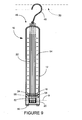
- Fig. 9 shows one of many types of enclosure 46 for the multi-channel manometer 10.
- This type preferably includes a hanging hook 48, by which the enclosure may be hung from handlebars of a motorcycle 50 (represented here by the dashed lines).
- the bottom of the enclosure 46 preferably includes a window 52, through which the static fluid level line 9 of the manometer fluid 20, can be seen, if the manometer housing 12 is translucent or transparent.
- Level markings 54 are preferably included to allow easy notation of the relative pressure levels in the manometer channels 22.
- Removable rubber feet 56 are also preferably included to provide a steady foundation for the manometer 10 when it is not to be hung by its hanging hook 48.
- Also preferably included are two compartments 58, whose lower ends are closed by the rubber feet 56.
- the adjustment screws can be seen at the top of the included slanted panel 16.
- the enclosure 46 can also be designed to prevent the adjustment screws 24 from being backed to far out of the reservoir 34 causing the o-ring 42 to leak.
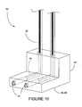
- Fig. 10 illustrates an alternate embodiment 60, in which the reservoir 34 is at right angles (90 degrees) to the upright portion 36, but which functions in a similar manner to that of the previous embodiment.
- the housing 62 of this embodiment 60 is "L-shaped', so that its housing bottom 64 provides a foot 66 for the device to sit upon. Again, there may be certain advantages to having the adjustment screws 24 presented at this 90 degree angle, which may be more convenient for the user to reach in certain applications. Only two channels are shown in this illustration, but it will be understood that the number of channels may again be eight or more, and that this illustration is not intended as a limitation on the number or dimensions of this embodiment.
- Fig. 11 illustrates another alternate embodiment 70 of a multi-channel manometer with independent reference-line adjustments. Again, four manometer channels 22 are shown, although this number is not to be taken as a limitation.
- This embodiment 70 is an example of an open-end manometer, meaning that the lower end is open to the atmosphere and it must be used in an upright position, rather than being closed, as in the previous embodiments.
- the manometer 70 includes a common reservoir 72 of manometer fluid 20, which is drawn up into the manometer tubes 18, when lower than atmospheric pressure is applied to the upper ends 74 of the tubes 18 through vacuum lines 6.
- the common reservoir 72 is at least partially open to atmospheric pressure, preferably through holes 76, which may be fitted with removable covers 78 to prevent spillage when the manometer 70 is to be moved, stored or to prevent evaporation.
- mercury is used widely as a manometer fluid, but in some states the sale of mercury has been ban because of health and safety concerns.
- Alternative manometer fluids 20 are lighter in weight than mercury, and thus are easier to draw up into the tubes 18.
- the tubes 18 In order to prevent these manometer fluids 20 from entering the vacuum lines 6 and emptying the common reservoir 72, as reduced pressure draws it out through the upper ends 74, the tubes 18 must be made longer and extend higher into the air, or the applied vacuum pull must be decreased. In order to make the tool a practical height to store and use in a shop environment and to minimize materials and space requirements, it is desirable to keep the tubes 18 short.
- valves 80 which can take many different forms, as will be obvious to those skilled in the art.
- One preferred type of valve 80 is a needle valve 82, which can be adjusted to introduce a small controlled amount of air into the vacuum line 6, which is indicated by the arrows pointing into the needle valve 82. By adjusting this needle valve 82, the reference-line 5 level can be independently adjusted in each of the channels 22.
- valve 80 Another very simple type of valve 80 is a simple T-connector which attaches to a short tube, which can be crimped to decrease air flow. Many other types of valves can be included including electronically controlled valves, and many types of manual valves.
- This alternate embodiment 70 can be used in much the same manner as the other previous embodiments. All channels 22 can be attached to a manifold from a single carburetor, the reference-line 5 levels adjusted, and then the vacuum lines 6 attached to the various carburetors for individual adjustment compared to this reference-line standard.
- the present multi-channel manometer 10 is well suited generally for adjusting pressures on multiple devices that require pressure regulation or synchronization such as multiple carburetors on a single motor, or for tuning multiple carburetors on separate motors.
- the goal is generally to have the air flow (and thus pressure) in each of the carburetors match as closely as possible to each other. Since it is the relative pressure in each carburetor with respect to each other that is important, the absolute pressure in each channel is not usually a concern.
- the purpose of using a manometer for pressure measurement is generally to equalize the pressures in all of the carburetors. It is easier and more efficient to be able to monitor all carburetors simultaneously, especially in cases where there may be some cross-effect, whereby the adjustment of a second carburetor affects the performance of the first.
- the present multi-channel manometer 10 allows easy simultaneous adjustment of all carburetors. All four channels 26,28,30,32 are first connected to a manifold 68, which takes the pressure from carburetor #1 1 and distributes it to all four of the manometer channels 26,28,30,32. To calibrate the manometer channels 26,28,30,32, they are exposed to a common pressure, the level in one manometer channel, such as channel #1 26 , is chosen as a reference, and the reference-line 5, to which the other channels will be tuned, is established as being parallel to this level. The other manometer channels 28,30,32 are adjusted by their adjustment screws 24 until all four channels 26,28,30,32 are at the reference-line 5 level.
- the manifold 68 is now detached from the vacuum lines 6 and the carburetors 1,2,3,4 are all attached individually to the four manometer channels 26,28,30,32.
- the levels in the manometer channels 26,28,30,32 will now vary again, as the pressure produced by the other un-tuned carburetors 2,3,4 is not uniform, but the reference-line 5 level still remains as a reference.
- the remaining carburetors 2,3,4 can now be adjusted by their adjustment mechanisms 7 until they all match the reference-line 5 level.
- the carburetors 1,2,3,4 will now all be synchronized.
- One type preferably includes a hanging hook 48, by which the enclosure may be hung from handlebars 50 of a motorcycle.
- the bottom of the enclosure 46 preferably includes a window 52, through which the static level 9 of the manometer fluid 20, can be seen, if the manometer housing 12 is translucent or transparent.
- Level markings 54 are preferably included to allow easy notation of the relative pressure levels in the manometer channels 22.
- Removable rubber feet 56 are also preferably included to provide a steady foundation for the manometer 10 when it is not to be hung by its hanging hook 48.
- FIG. 60 Another alternate embodiment 60 is shown in which the reservoir 34 is at right angles (90 degrees) to the upright portion 36.
- the housing 62 of this embodiment 60 is "L-shaped', so that its housing bottom 64 provides a foot 66 for the device to sit upon.
- Yet another alternate embodiment 70 of a multi-channel manometer with independent reference-line adjustments is that of an open-end manometer, meaning that the lower end is open to the atmosphere and it must be used in an upright position, rather than being closed, as in the previous embodiments.
- This variation of a manometer 70 includes a common reservoir 72 of manometer fluid 20, which is drawn up into the manometer tubes 18, when lower than atmospheric pressure is applied to the upper ends 74 of the tubes 18 through vacuum lines 6.
- the common reservoir 72 is at least partially open to atmospheric pressure, preferably through holes 76, which may be fitted with removable covers 78 to prevent spillage when the manometer 70 is to be moved, stored or to prevent evaporation.
- Alternative manometer fluids 20 may be lighter in weight than mercury, and thus are easier to draw up into the tubes 18.
- the tubes 18 In order to prevent these manometer fluids 20 from entering the vacuum lines 6 and emptying the common reservoir 72, as reduced pressure draws it out through the upper ends 74, the tubes 18 must be made longer and extend higher into the air, or the applied vacuum pull must be decreased. Thus, mechanisms have been included to "bleed" some of the vacuum pressure (actually to introduce a small amount of air at atmospheric pressure into the tubes) to decrease the vacuum pull (increase the pressure).
- Vacuum lines 6, which are connected to the carburetors are fitted for this purpose with valves 80 including needle valves 82, which can be adjusted to introduce a small controlled amount of air into the vacuum line 6. By adjusting this needle valve 82, the reference-line 5 level can be independently adjusted in each of the channels 22.
- valve 80 is a simple T-connector which attaches to a short tube, which can be crimped to decrease air flow.
- Many other types of valves can be included including electronically controlled valves, and many types of manual valves.
- 60,70 all channels 22 can be attached to a manifold from a single carburetor, the reference-line 5 levels adjusted, and then the vacuum lines 6 attached to the various carburetors for individual adjustment compared to this reference-line standard.
- all variations can provide for easy calibration of multiple carburetors, whether on a single vehicle, or on separate vehicles
Landscapes
- Physics & Mathematics (AREA)
- General Physics & Mathematics (AREA)
- Measuring Fluid Pressure (AREA)
Description
- The present invention relates generally to devices for measurement of pressure and more particularly to manometers for synchronization of engine carburetors.
- The carburetor is a device that mixes air and fuel for an internal combustion engine. The majority of motorcycles and many snowmobiles and outboard motors still are carbureted due to lower weight and cost compared to fuel-injected engines. Some carbureted engines have a single carburetor, though the modem trend is to use multiple carburetors, of two to eight carburetors. The carburetor works on Bernoulli's principle, which is that moving air has lower pressure than still air, and that the faster the movement of the air, the lower the pressure. The throttle or accelerator controls the amount of air that flows through the carburetor. Faster flows of air entering the carburetor draws more fuel into the carburetor due to the partial vacuum that is created. To function correctly under all conditions, most carburetors require tuning, and for engines with multiple carburetors, it is important that the carburetors be tuned together to provide balanced performance.
- A manometer is a pressure measuring instrument which is typically used when adjusting carburetors, whether single or multiple. It uses a column of liquid whose height in a glass tube indicates the pressure which is applied to the openings of the tube. Manometers can be of the type referred to as an "open-end manometer" which is generally "U-shaped" and has both ends open. One of the open ends is typically open to atmospheric pressure and the other end is then connected to a pressure source to be measured. By comparing the levels in the two legs of the U structure, the pressure of the pressure source can be measured compared to atmospheric pressure.
- The second type of manometer in common use is referred to as a "closed-end manometer" where one end is closed and thus a vacuum source connected to the open end pulls against the liquid in the closed tube. This generally gives a measurement of pressure which is lower than atmospheric pressure.
- When using manometers or other pressure measurement devices in tuning multiple carburettors in a vehicle, the goal is generally to have the air flow (and thus pressure) in each of the carburettors match as closely as possible to each other. Since it is the relative pressure in each carburettor with respect to each other that is important, the absolute pressure in each channel is not usually as concern. Thus, the purpose of using a manometer for pressure measurement is generally to equalize the pressure in all of the carburetors. It may be possible to do this with a single channel manometer, by noting the pressure in a first carburetor and then connecting the single channel manometer to each successive carburetor in turn, and this is a time consuming and inefficient method because carburetor adjustments affect engine performance and engine performance affects the pressure of previously adjusted carburettors, so it would have to be in iterative process, which would be very time consuming and with less assurance of success. It would be easier and more efficient to be able to monitor all carburettors simultaneously, especially in cases where there may be some cross-effect, whereby the adjustment of a second carburetor affects the performance of the first.
- Additionally, it would be an advantage if the fluid-level line in each of the channels of a multi-channel manometer could be individually adjusted, so that there would be maximum flexibility in the calibration of the multi-channels with respect to each other and to a pressure source, such as one of the carburettors in a multi-carburetor engine.
- Thus, there is a need for a multi-channel manometer with independent channel fluid-level adjustments for calibration.
-
US 3,315,527 A andUS 3,921,454 A disclose manometers having a plurality of channels.US 4,683,756 discloses a manometer including a reservoir portion and an adjustment mechanism. - Accordingly, it is an object of the present invention to allow for the turning of multiple carburetors with a single device.
- Another object of the invention is to provide a manometer with multiple channels.
- And another object of the invention is to provide a manometer with multiple channels which each have a fluid-level adjustment.
- A further object of the present invention is to provide multiple manometer channels which can be adjusted in relation to each other independently.
- An additional object of the present invention is to provide a manometer which does not use mercury as a level indicator fluid.
- Yet another object of the present invention is to provide a tool in which multiple manometers are grouped together in a single device.
Another object of the present invention is to provide a manometer with multiple channels that can be used independently. The tool can be used as a 1, 2, 3, or 4 channel manometer. - Briefly, one preferred embodiment of the present invention is a manometer for multi-channel pressure measurement which includes two or more manometer channels, where each channel includes an independent fluid level adjustment. Also included is a method for calibrating multiple carburetors using a manometer having multiple channels, each having an independent fluid level adjustment.
- An advantage of the present invention is that multiple carburetors on the same or separate vehicle can be adjusted simultaneously.
- Another advantage of the present invention is that multiple pressure-measuring devices are grouped in a single device so that they may be easily compared side-by-side.
- And another advantage of the present invention is that each of the multiple channels is independently adjustable to set a reference-line for each, or to set a common reference-line used by all channels.
- A further advantage of the present invention is that adjustment screws for each channel are grouped in a configuration that is easily accessible for manipulation.
- A yet further advantage is that the multiple manometer channels are grouped in a freestanding housing that provides a stable base of support for the manometers.
- Another advantage of the present invention is the free standing housing provides reference marks so the user can clearly see when the fluid-levels of the multiple channels are aligned.
- And another advantage of the present invention is that each channel is independent of the other channels allowing the user to use as few or as many of the channels as they need.
- A further advantage of the present invention is that the manometer does not have to be kept in the upright position while being used or stored to prevent the level indicator fluid from running out of the reservoirs.
- These and other objects and advantages of the present invention will become clear to those skilled in the art in view of the description of the best presently known mode of carrying out the invention and the industrial applicability of the preferred embodiment as described herein and as illustrated in the several figures of the drawings.
- The purposes and advantages of the present invention will be apparent from the following detailed description in conjunction with the appended drawings in which:
-
FIG. 1 shows an isometric view of the multi-channel manometer of the present invention; -
FIG. 2 shows a side plan view of the multi-channel manometer of the present invention; -
FIG. 3 shows a front plan view of the multi-channel manometer of the present invention; -
FIG. 4 shows a cross-section view of the multi-channel manometer of the present invention as taken through line 4-4 ofFig. 3 ; -
FIG. 5 shows an isometric view of the multi-channel manometer of the present invention showing the adjustment screw manipulation; -
FIGS. 6-8 show front plan views of the adjustment of carburetors using the multi-channel manometer of the present invention; -
FIG. 9 shows a front plan view of an enclosure for a closed-end manometer of the present invention; -
FIG. 10 illustrates an isometric view of an alternative embodiment of a multi-channel manometer; and -
FIG. 11 illustrates a front plan view of a second alternate embodiment of a multi-channel manometer. - The present invention is an adjustable multi-channel manometer, which will be referred to by the
reference number 10, and thus, for simplicity, shall be referred to asmanometer 10. A first preferred embodiment of themanometer 10 is illustrated inFigs. 1-5 , of whichFig. 1 is a perspective view,Fig. 2 is a side plan view, andFig. 3 is a front plan view. Generally, themanometer 10 includes ahousing 12 having afront face 14 which includes aslanted panel 16. Thehousing 12 is preferably, but not necessarily, translucent or transparent, so the fluid levels in thehousing 12 may be observed. A number ofmanometer tubes 18 are grouped in thehousing 12, and eachmanometer tube 18 includes a column ofmanometer fluid 20. Thetubes 18 andfluid 20 are included in each of themanometer channels 22, along with other elements which will be discussed below. Theslanted panel 16 includes a number ofadjustment screws 24, of which there is one for each of themanometer channels 22. These adjustment screws 24 are important for setting thereference line 5 in eachchannel 22, as will be discussed below. - Four
manometer channels 22 are shown in the embodiment ofFig. 1 . These shall be referred to aschannel # 1 26,channel # 2 28,channel # 3 30 andchannel # 4 32. It shall be understood by those skilled in the art that the number of channels is not restricted to four. There could be as few as two channels, and the number of channels could be eight or more, depending on the number of devices which are intended to be calibrated. Themulti-channel manometer 10 could be used to tune two carburetors on a vehicle, or could be used to tune eight carburetors on 8 vehicles, etc. Thus, the numbers of channels shown in the illustrations are not to be construed as limitations. -
Fig. 1 also shows four carburetors, designated ascarburetor # 1, designatedelement 1,carburetor # 2 2,carburetor # 3 3, andcarburetor # 4 4.Carburetor # 1 1 is shown to be connected tomanometer channel # 1 26 by avacuum line 6, and theother carburetors channels carburetor own adjustment mechanism 7 which controls the air flow in the carburetor in order to tune its performance. The goal in tuning multiple carburetors in a vehicle is generally to have the air flow in each carburetor match as closely as possible to each other. Since it is the relative pressure in each carburetor with respect to each other that is important, the absolute pressure in each channel is not usually a concern. Thus, the purpose of using a manometer for pressure measurement is generally to equalize the pressures in all of the carburetors. -
Fig. 4 is a cross-sectional view of one of themanometer channels 22 as taken through section-line 4-4 inFig. 3 . It can be seen that the interior ofhousing 12 encloses a portion of themanometer channel 22. Themanometer channel 22 thus includes areservoir 34 which connects to anupright portion 36 at anangle α 38, which can be any one of a great variety of angles, as will be discussed below. Theadjustment screw 24 is seated in a threadedconnector portion 40, so that the adjustment screw can be easily advanced or retreated down thereservoir 34. The o-ring 42 on theadjustment screw 24 provides a seal between theadjustment screw 24 and thereservoir 34. Thus, when theadjustment screw 24 is advanced in the threadedconnector portion 40, it puts pressure on themanometer fluid 20 which forces it higher into theupright portion 36, which is preferably at a height that is above the top of thehousing 12, and can be easily seen by the user. - This is illustrated in
Fig. 5 , where anadjustment tool 8, preferably a screwdriver, is shown turning theadjustment screw 24, forcingmanometer fluid 20 from thereservoir 34 higher in theupright portion 36. Eachchannel 22 has itsown adjustment screw 24, and is therefore independently adjustable. Thus, the levels ofmanometer fluid 20 in each channel can be easily calibrated, to set a reference-line 5 for each. This can be done before thecarburetors line 5 can be set by attaching eachchannel 22 to one of thecarburetors - The
manometer fluid 20 can be of many different types. Some styles of manometers use mercury, since it is a very heavy liquid with a specific gravity of 13.546, and thus a shorter column of fluid is needed in a manometer, relative to lighter fluids. However, mercury is a very toxic material, and involves many safety and disposal problems. Other manometer fluids are available, but their specific gravity ranges from approximately 1.0 to 2.0 which means that the column height is 13 to 6.5 times the equivalent height of mercury when used in an open-end manometer. - As discussed above, the angle α 38 of the
reservoir 34 relative to theupright portion 36, is subject to much variation. The presently preferred angle is in a range of 0-90 degrees, but this angle could vary anywhere from 0 degrees, where the manometer channel describes a "U" structure, to a 90 degree right angle structure, to a full 180 degree structure, where the adjustment screws 24 are at the bottom of astraight tube 18, which is in line with theupright portion 36. The angle α 38 and thus the placement of thereservoir 34 and adjustment screws 24 largely depends on what angle the tool will most likely be used in so a static head ofmanometer fluid 20 remains above the bottom of thetubes 18 and a convenient location to access the adjustment screws 24 for the user. In the present embodiment, the screws were placed at the preferred angle of 15 degrees because the tool is most likely to be used in a vertical or horizontal position. Thus it will be obvious to those skilled in the art that theangle α 38 can be configured wherever depending on the intended use of the tool and so the convenience of the user can be best accommodated. - In the embodiment of
Figs. 1-5 , based on the intended use of the tool and for the convenience of the user, themanometer channels 22 are enclosed in thehousing 12, which can stand upright upon itshousing bottom 44, and the slantedpanel 16 is included to more easily provide access to the adjustment screws 24. - The present
multichannel manometer 10 can be used for adjusting pressures on multiple devices that require calibrated pressure regulation such as multiple carburetors.Figs. 6 - 8 show various stages in the process of tuning multiple carburetors using themulti-channel manometer 10 of the present invention. InFig. 6 , it will be assumed that there are four carburetors to be tuned and that themanometer 10 has fourchannels - All four
channels carburetor # 1 1 and distributes it to all four of themanometer channels manometer channels manometer channels Fig. 6 . The level inmanometer channel # 1 26 is chosen as a reference, and the reference-line 5, to which the other channels will be tuned, is established as being parallel to this level. - In
Fig. 7 , the threeother manometer channels channels line 5 level. - As shown in
Fig. 8 , the manifold 68 (seeFig. 7 ) is now detached from thevacuum lines 6 and thecarburetors manometer channels manometer channels un-tuned carburetors line 5 level still remains as a reference. The remainingcarburetors adjustment mechanisms 7 until they all match the reference-line 5 level. Thecarburetors - It will be understood that there are many other variations of procedure for tuning multiple carburetors which may be practiced using the multi-channel manometer, and these will be obvious to one skilled in the art. The previous method thus is not meant to be a limitation, but an example of one use.
-
Fig. 9 shows one of many types ofenclosure 46 for themulti-channel manometer 10. This type preferably includes a hanginghook 48, by which the enclosure may be hung from handlebars of a motorcycle 50 (represented here by the dashed lines). The bottom of theenclosure 46 preferably includes awindow 52, through which the staticfluid level line 9 of themanometer fluid 20, can be seen, if themanometer housing 12 is translucent or transparent.Level markings 54 are preferably included to allow easy notation of the relative pressure levels in themanometer channels 22.Removable rubber feet 56 are also preferably included to provide a steady foundation for themanometer 10 when it is not to be hung by its hanginghook 48. Also preferably included are twocompartments 58, whose lower ends are closed by therubber feet 56. These compartments can provide storage space for vacuum caps, carburetor adaptors, lines, or other items when they are not in use. The adjustment screws can be seen at the top of the included slantedpanel 16. Theenclosure 46 can also be designed to prevent the adjustment screws 24 from being backed to far out of thereservoir 34 causing the o-ring 42 to leak. - It will be obvious to one skilled in the art that many other variations of enclosures are possible, which may take many other shapes and forms. The present illustration is not to be taken as a limitation.
-
Fig. 10 illustrates analternate embodiment 60, in which thereservoir 34 is at right angles (90 degrees) to theupright portion 36, but which functions in a similar manner to that of the previous embodiment. Thehousing 62 of thisembodiment 60 is "L-shaped', so that its housing bottom 64 provides a foot 66 for the device to sit upon. Again, there may be certain advantages to having the adjustment screws 24 presented at this 90 degree angle, which may be more convenient for the user to reach in certain applications. Only two channels are shown in this illustration, but it will be understood that the number of channels may again be eight or more, and that this illustration is not intended as a limitation on the number or dimensions of this embodiment. -
Fig. 11 illustrates anotheralternate embodiment 70 of a multi-channel manometer with independent reference-line adjustments. Again, fourmanometer channels 22 are shown, although this number is not to be taken as a limitation. Thisembodiment 70 is an example of an open-end manometer, meaning that the lower end is open to the atmosphere and it must be used in an upright position, rather than being closed, as in the previous embodiments. - The
manometer 70 includes acommon reservoir 72 ofmanometer fluid 20, which is drawn up into themanometer tubes 18, when lower than atmospheric pressure is applied to the upper ends 74 of thetubes 18 throughvacuum lines 6. As mentioned above, thecommon reservoir 72 is at least partially open to atmospheric pressure, preferably throughholes 76, which may be fitted withremovable covers 78 to prevent spillage when themanometer 70 is to be moved, stored or to prevent evaporation. - As referred to above, mercury is used widely as a manometer fluid, but in some states the sale of mercury has been ban because of health and safety concerns.
Alternative manometer fluids 20 are lighter in weight than mercury, and thus are easier to draw up into thetubes 18. In order to prevent thesemanometer fluids 20 from entering thevacuum lines 6 and emptying thecommon reservoir 72, as reduced pressure draws it out through the upper ends 74, thetubes 18 must be made longer and extend higher into the air, or the applied vacuum pull must be decreased. In order to make the tool a practical height to store and use in a shop environment and to minimize materials and space requirements, it is desirable to keep thetubes 18 short. Thus, mechanisms have been included to "bleed" some of the vacuum pressure (actually to introduce a small amount of air at atmospheric pressure into the tubes) to decrease the vacuum pull (increase the pressure). The vacuum lines 6, which are connected to the carburetors (not shown), are fitted for this purpose with valves 80 which can take many different forms, as will be obvious to those skilled in the art. One preferred type of valve 80 is aneedle valve 82, which can be adjusted to introduce a small controlled amount of air into thevacuum line 6, which is indicated by the arrows pointing into theneedle valve 82. By adjusting thisneedle valve 82, the reference-line 5 level can be independently adjusted in each of thechannels 22. - Another very simple type of valve 80 is a simple T-connector which attaches to a short tube, which can be crimped to decrease air flow. Many other types of valves can be included including electronically controlled valves, and many types of manual valves.
- This
alternate embodiment 70 can be used in much the same manner as the other previous embodiments. Allchannels 22 can be attached to a manifold from a single carburetor, the reference-line 5 levels adjusted, and then thevacuum lines 6 attached to the various carburetors for individual adjustment compared to this reference-line standard. - The present
multi-channel manometer 10 is well suited generally for adjusting pressures on multiple devices that require pressure regulation or synchronization such as multiple carburetors on a single motor, or for tuning multiple carburetors on separate motors. When using manometers or other pressure measurement devices in tuning multiple carburetors on a motor, the goal is generally to have the air flow (and thus pressure) in each of the carburetors match as closely as possible to each other. Since it is the relative pressure in each carburetor with respect to each other that is important, the absolute pressure in each channel is not usually a concern. Thus, the purpose of using a manometer for pressure measurement is generally to equalize the pressures in all of the carburetors. It is easier and more efficient to be able to monitor all carburetors simultaneously, especially in cases where there may be some cross-effect, whereby the adjustment of a second carburetor affects the performance of the first. - The present
multi-channel manometer 10 allows easy simultaneous adjustment of all carburetors. All fourchannels carburetor # 1 1 and distributes it to all four of themanometer channels manometer channels channel # 1 26, is chosen as a reference, and the reference-line 5, to which the other channels will be tuned, is established as being parallel to this level. Theother manometer channels channels line 5 level. - The manifold 68 is now detached from the
vacuum lines 6 and thecarburetors manometer channels manometer channels un-tuned carburetors line 5 level still remains as a reference. The remainingcarburetors adjustment mechanisms 7 until they all match the reference-line 5 level. Thecarburetors - It will be understood that there are many other variations of procedure for tuning multiple carburetors which may be practiced using the multi-channel manometer.
- There are many types of
enclosures 46 for themulti-channel manometer 10. One type preferably includes a hanginghook 48, by which the enclosure may be hung fromhandlebars 50 of a motorcycle. The bottom of theenclosure 46 preferably includes awindow 52, through which thestatic level 9 of themanometer fluid 20, can be seen, if themanometer housing 12 is translucent or transparent.Level markings 54 are preferably included to allow easy notation of the relative pressure levels in themanometer channels 22.Removable rubber feet 56 are also preferably included to provide a steady foundation for themanometer 10 when it is not to be hung by its hanginghook 48. - Another
alternate embodiment 60 is shown in which thereservoir 34 is at right angles (90 degrees) to theupright portion 36. Thehousing 62 of thisembodiment 60 is "L-shaped', so that its housing bottom 64 provides a foot 66 for the device to sit upon. - Yet another
alternate embodiment 70 of a multi-channel manometer with independent reference-line adjustments is that of an open-end manometer, meaning that the lower end is open to the atmosphere and it must be used in an upright position, rather than being closed, as in the previous embodiments. This variation of amanometer 70 includes acommon reservoir 72 ofmanometer fluid 20, which is drawn up into themanometer tubes 18, when lower than atmospheric pressure is applied to the upper ends 74 of thetubes 18 throughvacuum lines 6. Thecommon reservoir 72 is at least partially open to atmospheric pressure, preferably throughholes 76, which may be fitted withremovable covers 78 to prevent spillage when themanometer 70 is to be moved, stored or to prevent evaporation. -
Alternative manometer fluids 20 may be lighter in weight than mercury, and thus are easier to draw up into thetubes 18. In order to prevent thesemanometer fluids 20 from entering thevacuum lines 6 and emptying thecommon reservoir 72, as reduced pressure draws it out through the upper ends 74, thetubes 18 must be made longer and extend higher into the air, or the applied vacuum pull must be decreased. Thus, mechanisms have been included to "bleed" some of the vacuum pressure (actually to introduce a small amount of air at atmospheric pressure into the tubes) to decrease the vacuum pull (increase the pressure).Vacuum lines 6, which are connected to the carburetors are fitted for this purpose with valves 80 includingneedle valves 82, which can be adjusted to introduce a small controlled amount of air into thevacuum line 6. By adjusting thisneedle valve 82, the reference-line 5 level can be independently adjusted in each of thechannels 22. - Another very simple type of valve 80 is a simple T-connector which attaches to a short tube, which can be crimped to decrease air flow. Many other types of valves can be included including electronically controlled valves, and many types of manual valves. In these
alternate embodiments channels 22 can be attached to a manifold from a single carburetor, the reference-line 5 levels adjusted, and then thevacuum lines 6 attached to the various carburetors for individual adjustment compared to this reference-line standard. Thus all variations can provide for easy calibration of multiple carburetors, whether on a single vehicle, or on separate vehicles - Other advantages of the present invention include the ability to use manometer fluids with relatively low specific gravities when compared to mercury in a configuration that is compact and economical to manufacture when compared to electronic and other mechanical alternatives.
- For the above, and other, reasons, it is expected that the
multi-channel manometer 10 of the present invention will have widespread industrial applicability. Therefore, it is expected that the commercial utility of the present invention will be extensive and long lasting.
Claims (15)
- A manometer (10) for multi-channel pressure measurement comprising a plurality of manometer channels (22) characterised in that each channel has an independent fluid level adjustment (24, 40).
- The manometer of Claim 1, wherein each of said plurality of manometer channels includes a tube (36) which contains manometer fluid.
- The manometer of Claim 2, wherein each said tube includes a reservoir portion (34) and an adjustment mechanism (24, 40) which adjusts fluid levels in each of said plurality of manometer channels.
- The manometer of Claim 3, wherein said adjustment mechanism includes an adjustment screw (24).
- The manometer of Claim 1, wherein said plurality of manometer channels are grouped together in a housing (12).
- The manometer of Claim 5, wherein said housing includes a slanted panel (16).
- The manometer of Claim 1, wherein each of said plurality of manometer channels includes a reservoir (34) and an upright portion (36).
- The manometer of Claim 7, wherein said reservoir and said upright portion join at an angle α.
- The manometer of Claim 8, wherein said angle α lies in the range of 0-180 degrees.
- The manometer of Claim 4, further comprising a threaded connector portion (40) to which said adjustment screw (24) is threadably engaged.
- The manometer of Claim 6, wherein said adjustment screws are set into said slanted panel of said housing.
- The manometer of Claim 5, wherein said housing includes a hanging hook (48).
- The manometer of Claim 2, wherein said manometer includes a common reservoir of fluid (72) to which each of said tubes of said plurality of manometer channels are connected.
- The manometer of Claim 13, wherein each said tube is attached to a valve (80) by which fluid level in each of said manometer channels may be adjusted independently.
- A method for adjusting multiple carburetors to a common pressure, comprising:A) providing a manometer (10) having a plurality of channels (22), characterised in that each channel includes an independent pressure level adjustment (24, 40) and an independent pressure level indicator;B) attaching all of said plurality of channels to a common pressure source;C) choosing one of said channels as a reference channel and noting the level of pressure level indicator of said reference channel to provide a reference level (5);D) adjusting the independent pressure level adjustments of each of said plurality of channels such that said pressure level indicator levels of each of said plurality of channels approximates said reference level of said reference channel;E) connecting vacuum lines (6) from each carburetor of said multiple carburetors so that each carburetor is connected to a separate channel of said plurality of channels of said manometer; andF) adjusting each of said carburetors until each of said pressure level indicators of said plurality of channels are approximately equal.
Applications Claiming Priority (3)
| Application Number | Priority Date | Filing Date | Title |
|---|---|---|---|
| US82922306P | 2006-10-12 | 2006-10-12 | |
| US11/870,767 US7516670B2 (en) | 2006-10-12 | 2007-10-11 | Multi-channel manometer with independent fluid level adjustments |
| PCT/US2007/081190 WO2008046034A2 (en) | 2006-10-12 | 2007-10-12 | Multi-channel manometer with independent fluid level adjustments |
Publications (3)
| Publication Number | Publication Date |
|---|---|
| EP2074398A2 EP2074398A2 (en) | 2009-07-01 |
| EP2074398A4 EP2074398A4 (en) | 2011-01-12 |
| EP2074398B1 true EP2074398B1 (en) | 2015-12-09 |
Family
ID=39283647
Family Applications (1)
| Application Number | Title | Priority Date | Filing Date |
|---|---|---|---|
| EP07853975.6A Active EP2074398B1 (en) | 2006-10-12 | 2007-10-12 | Multi-channel manometer with independent fluid level adjustments |
Country Status (3)
| Country | Link |
|---|---|
| US (1) | US7516670B2 (en) |
| EP (1) | EP2074398B1 (en) |
| WO (1) | WO2008046034A2 (en) |
Families Citing this family (3)
| Publication number | Priority date | Publication date | Assignee | Title |
|---|---|---|---|---|
| KR101433223B1 (en) | 2012-12-14 | 2014-08-26 | 교통안전공단 | Meter for soot test |
| CN105403348B (en) * | 2015-10-29 | 2019-01-01 | 中国空气动力研究与发展中心设备设计及测试技术研究所 | One kind may be programmed highly integrated multi-path pressure test device |
| CN106441698B (en) * | 2016-11-24 | 2018-04-27 | 中国石油大学(北京) | The unstable pressure difference meter of high pressure and its use and check method |
Family Cites Families (15)
| Publication number | Priority date | Publication date | Assignee | Title |
|---|---|---|---|---|
| US1812152A (en) | 1929-05-11 | 1931-06-30 | Milton O Jensen | Manometer gauge |
| US1917846A (en) | 1929-05-11 | 1933-07-11 | Central Scientific Co | Gas pressure apparatus |
| US2494936A (en) | 1944-07-08 | 1950-01-17 | Carter Carburetor Corp | Carburetor testing device and method |
| US3315527A (en) | 1964-10-22 | 1967-04-25 | Richard W Foster-Pegg | Manometer apparatus |
| US3459032A (en) | 1967-07-06 | 1969-08-05 | Roger Gilmont Instr Inc | Manometer calibrating device and methods |
| US3538933A (en) * | 1967-08-07 | 1970-11-10 | British Oxygen Co Ltd | Fluid mixing device |
| US3921454A (en) * | 1974-04-02 | 1975-11-25 | Iv Sterling B Reames | Multi-indicating vacuum gauge |
| FR2513698A1 (en) | 1981-09-30 | 1983-04-01 | Sibe | METHOD AND INSTALLATION FOR INSPECTION OF CARBURETORS |
| US4455876A (en) | 1982-09-27 | 1984-06-26 | The United States Of America As Represented By The United States Department Of Energy | Precision manometer gauge |
| US4563892A (en) | 1984-07-24 | 1986-01-14 | Aoust Brian G D | Total dissolved gas pressure measuring device |
| US4683756A (en) * | 1986-01-24 | 1987-08-04 | Xerox Corporation | Low cost manometer |
| GB8728468D0 (en) * | 1987-12-04 | 1988-01-13 | Sonceboz Sa | Fluidic flowmeter |
| US5609060A (en) * | 1995-04-28 | 1997-03-11 | Dentsleeve Pty Limited | Multiple channel perfused manometry apparatus and a method of operation of such a device |
| US5895862A (en) * | 1997-02-24 | 1999-04-20 | Peabody; Steven R. | Manometer |
| US6510741B2 (en) * | 2000-09-06 | 2003-01-28 | Dwyer Instruments, Inc. | Manometer having dual pressure sensors |
-
2007
- 2007-10-11 US US11/870,767 patent/US7516670B2/en active Active
- 2007-10-12 EP EP07853975.6A patent/EP2074398B1/en active Active
- 2007-10-12 WO PCT/US2007/081190 patent/WO2008046034A2/en not_active Ceased
Also Published As
| Publication number | Publication date |
|---|---|
| EP2074398A4 (en) | 2011-01-12 |
| EP2074398A2 (en) | 2009-07-01 |
| WO2008046034A3 (en) | 2008-08-21 |
| US20080087096A1 (en) | 2008-04-17 |
| WO2008046034A2 (en) | 2008-04-17 |
| US7516670B2 (en) | 2009-04-14 |
Similar Documents
| Publication | Publication Date | Title |
|---|---|---|
| US5425265A (en) | Apparatus and method for measuring the capillary pressure distribution of porous materials | |
| US7516670B2 (en) | Multi-channel manometer with independent fluid level adjustments | |
| US6981426B2 (en) | Method and apparatus to measure gas amounts adsorbed on a powder sample | |
| US6848292B2 (en) | System for calibration of pressure transducers | |
| US4275752A (en) | Fluid flow apparatus and method | |
| ES2234711T3 (en) | PROCEDURE AND DEVICE FOR DETEMINATING PERMEABILITY TO THE GAS OF A CONTAINER. | |
| US12521713B2 (en) | Method and apparatus to identify fluidic path positions | |
| EP1068507A1 (en) | Method and device for measuring gas permeability through a porous membrane-like material | |
| US4563892A (en) | Total dissolved gas pressure measuring device | |
| US5481921A (en) | Snap-fit assembly of direct drive Bourdon tube pressure gauge | |
| US5808188A (en) | Flowbench and air flow measurement and calibration procedure | |
| CN1042773A (en) | The improvement of the sensor and the parties concerned thereof | |
| US2858697A (en) | entwistle | |
| US20080189967A1 (en) | Standardizable level tool | |
| US2494936A (en) | Carburetor testing device and method | |
| CN218573313U (en) | Gas mixing diluter | |
| CN217542354U (en) | Dynamic flow testing machine for oil nozzle | |
| JP2000501154A (en) | Diaphragm carburetor | |
| US20030033856A1 (en) | Test device for filter systems | |
| US20070219537A1 (en) | Pressure gauge display for chest drainage unit | |
| US3138959A (en) | Multiple carburetor air flow measuring device | |
| US3835548A (en) | Hydrostatic leveling apparatus with control operator | |
| JP2779913B2 (en) | Pore distribution measuring device and metering injector | |
| CN207557222U (en) | A kind of flammable calibrating installation with toxic and harmful gas alarm | |
| US3921454A (en) | Multi-indicating vacuum gauge |
Legal Events
| Date | Code | Title | Description |
|---|---|---|---|
| PUAI | Public reference made under article 153(3) epc to a published international application that has entered the european phase |
Free format text: ORIGINAL CODE: 0009012 |
|
| 17P | Request for examination filed |
Effective date: 20090402 |
|
| AK | Designated contracting states |
Kind code of ref document: A2 Designated state(s): AT BE BG CH CY CZ DE DK EE ES FI FR GB GR HU IE IS IT LI LT LU LV MC MT NL PL PT RO SE SI SK TR |
|
| AX | Request for extension of the european patent |
Extension state: AL BA HR MK RS |
|
| DAX | Request for extension of the european patent (deleted) | ||
| A4 | Supplementary search report drawn up and despatched |
Effective date: 20101213 |
|
| 17Q | First examination report despatched |
Effective date: 20110321 |
|
| GRAP | Despatch of communication of intention to grant a patent |
Free format text: ORIGINAL CODE: EPIDOSNIGR1 |
|
| RIC1 | Information provided on ipc code assigned before grant |
Ipc: G01L 7/18 20060101AFI20150827BHEP Ipc: G01M 15/00 20060101ALI20150827BHEP |
|
| INTG | Intention to grant announced |
Effective date: 20150915 |
|
| GRAS | Grant fee paid |
Free format text: ORIGINAL CODE: EPIDOSNIGR3 |
|
| GRAA | (expected) grant |
Free format text: ORIGINAL CODE: 0009210 |
|
| AK | Designated contracting states |
Kind code of ref document: B1 Designated state(s): AT BE BG CH CY CZ DE DK EE ES FI FR GB GR HU IE IS IT LI LT LU LV MC MT NL PL PT RO SE SI SK TR |
|
| REG | Reference to a national code |
Ref country code: GB Ref legal event code: FG4D |
|
| REG | Reference to a national code |
Ref country code: AT Ref legal event code: REF Ref document number: 764791 Country of ref document: AT Kind code of ref document: T Effective date: 20151215 Ref country code: CH Ref legal event code: EP |
|
| REG | Reference to a national code |
Ref country code: IE Ref legal event code: FG4D |
|
| REG | Reference to a national code |
Ref country code: DE Ref legal event code: R096 Ref document number: 602007044210 Country of ref document: DE |
|
| REG | Reference to a national code |
Ref country code: SE Ref legal event code: TRGR |
|
| REG | Reference to a national code |
Ref country code: LT Ref legal event code: MG4D |
|
| REG | Reference to a national code |
Ref country code: NL Ref legal event code: MP Effective date: 20151209 |
|
| PG25 | Lapsed in a contracting state [announced via postgrant information from national office to epo] |
Ref country code: LT Free format text: LAPSE BECAUSE OF FAILURE TO SUBMIT A TRANSLATION OF THE DESCRIPTION OR TO PAY THE FEE WITHIN THE PRESCRIBED TIME-LIMIT Effective date: 20151209 Ref country code: ES Free format text: LAPSE BECAUSE OF FAILURE TO SUBMIT A TRANSLATION OF THE DESCRIPTION OR TO PAY THE FEE WITHIN THE PRESCRIBED TIME-LIMIT Effective date: 20151209 |
|
| REG | Reference to a national code |
Ref country code: AT Ref legal event code: MK05 Ref document number: 764791 Country of ref document: AT Kind code of ref document: T Effective date: 20151209 |
|
| PG25 | Lapsed in a contracting state [announced via postgrant information from national office to epo] |
Ref country code: FI Free format text: LAPSE BECAUSE OF FAILURE TO SUBMIT A TRANSLATION OF THE DESCRIPTION OR TO PAY THE FEE WITHIN THE PRESCRIBED TIME-LIMIT Effective date: 20151209 Ref country code: NL Free format text: LAPSE BECAUSE OF FAILURE TO SUBMIT A TRANSLATION OF THE DESCRIPTION OR TO PAY THE FEE WITHIN THE PRESCRIBED TIME-LIMIT Effective date: 20151209 Ref country code: LV Free format text: LAPSE BECAUSE OF FAILURE TO SUBMIT A TRANSLATION OF THE DESCRIPTION OR TO PAY THE FEE WITHIN THE PRESCRIBED TIME-LIMIT Effective date: 20151209 Ref country code: GR Free format text: LAPSE BECAUSE OF FAILURE TO SUBMIT A TRANSLATION OF THE DESCRIPTION OR TO PAY THE FEE WITHIN THE PRESCRIBED TIME-LIMIT Effective date: 20160310 |
|
| PG25 | Lapsed in a contracting state [announced via postgrant information from national office to epo] |
Ref country code: IS Free format text: LAPSE BECAUSE OF FAILURE TO SUBMIT A TRANSLATION OF THE DESCRIPTION OR TO PAY THE FEE WITHIN THE PRESCRIBED TIME-LIMIT Effective date: 20151209 |
|
| PG25 | Lapsed in a contracting state [announced via postgrant information from national office to epo] |
Ref country code: IT Free format text: LAPSE BECAUSE OF FAILURE TO SUBMIT A TRANSLATION OF THE DESCRIPTION OR TO PAY THE FEE WITHIN THE PRESCRIBED TIME-LIMIT Effective date: 20151209 Ref country code: CZ Free format text: LAPSE BECAUSE OF FAILURE TO SUBMIT A TRANSLATION OF THE DESCRIPTION OR TO PAY THE FEE WITHIN THE PRESCRIBED TIME-LIMIT Effective date: 20151209 |
|
| PG25 | Lapsed in a contracting state [announced via postgrant information from national office to epo] |
Ref country code: AT Free format text: LAPSE BECAUSE OF FAILURE TO SUBMIT A TRANSLATION OF THE DESCRIPTION OR TO PAY THE FEE WITHIN THE PRESCRIBED TIME-LIMIT Effective date: 20151209 Ref country code: IS Free format text: LAPSE BECAUSE OF FAILURE TO SUBMIT A TRANSLATION OF THE DESCRIPTION OR TO PAY THE FEE WITHIN THE PRESCRIBED TIME-LIMIT Effective date: 20160409 Ref country code: RO Free format text: LAPSE BECAUSE OF FAILURE TO SUBMIT A TRANSLATION OF THE DESCRIPTION OR TO PAY THE FEE WITHIN THE PRESCRIBED TIME-LIMIT Effective date: 20151209 Ref country code: EE Free format text: LAPSE BECAUSE OF FAILURE TO SUBMIT A TRANSLATION OF THE DESCRIPTION OR TO PAY THE FEE WITHIN THE PRESCRIBED TIME-LIMIT Effective date: 20151209 Ref country code: PT Free format text: LAPSE BECAUSE OF FAILURE TO SUBMIT A TRANSLATION OF THE DESCRIPTION OR TO PAY THE FEE WITHIN THE PRESCRIBED TIME-LIMIT Effective date: 20160411 Ref country code: SK Free format text: LAPSE BECAUSE OF FAILURE TO SUBMIT A TRANSLATION OF THE DESCRIPTION OR TO PAY THE FEE WITHIN THE PRESCRIBED TIME-LIMIT Effective date: 20151209 |
|
| REG | Reference to a national code |
Ref country code: DE Ref legal event code: R097 Ref document number: 602007044210 Country of ref document: DE |
|
| PLBE | No opposition filed within time limit |
Free format text: ORIGINAL CODE: 0009261 |
|
| STAA | Information on the status of an ep patent application or granted ep patent |
Free format text: STATUS: NO OPPOSITION FILED WITHIN TIME LIMIT |
|
| REG | Reference to a national code |
Ref country code: FR Ref legal event code: PLFP Year of fee payment: 10 |
|
| PG25 | Lapsed in a contracting state [announced via postgrant information from national office to epo] |
Ref country code: PL Free format text: LAPSE BECAUSE OF FAILURE TO SUBMIT A TRANSLATION OF THE DESCRIPTION OR TO PAY THE FEE WITHIN THE PRESCRIBED TIME-LIMIT Effective date: 20151209 Ref country code: DK Free format text: LAPSE BECAUSE OF FAILURE TO SUBMIT A TRANSLATION OF THE DESCRIPTION OR TO PAY THE FEE WITHIN THE PRESCRIBED TIME-LIMIT Effective date: 20151209 |
|
| 26N | No opposition filed |
Effective date: 20160912 |
|
| PG25 | Lapsed in a contracting state [announced via postgrant information from national office to epo] |
Ref country code: SI Free format text: LAPSE BECAUSE OF FAILURE TO SUBMIT A TRANSLATION OF THE DESCRIPTION OR TO PAY THE FEE WITHIN THE PRESCRIBED TIME-LIMIT Effective date: 20151209 |
|
| PG25 | Lapsed in a contracting state [announced via postgrant information from national office to epo] |
Ref country code: BE Free format text: LAPSE BECAUSE OF FAILURE TO SUBMIT A TRANSLATION OF THE DESCRIPTION OR TO PAY THE FEE WITHIN THE PRESCRIBED TIME-LIMIT Effective date: 20151209 |
|
| REG | Reference to a national code |
Ref country code: CH Ref legal event code: PL |
|
| REG | Reference to a national code |
Ref country code: IE Ref legal event code: MM4A |
|
| PG25 | Lapsed in a contracting state [announced via postgrant information from national office to epo] |
Ref country code: LI Free format text: LAPSE BECAUSE OF NON-PAYMENT OF DUE FEES Effective date: 20161031 Ref country code: CH Free format text: LAPSE BECAUSE OF NON-PAYMENT OF DUE FEES Effective date: 20161031 |
|
| PG25 | Lapsed in a contracting state [announced via postgrant information from national office to epo] |
Ref country code: LU Free format text: LAPSE BECAUSE OF NON-PAYMENT OF DUE FEES Effective date: 20161012 |
|
| REG | Reference to a national code |
Ref country code: FR Ref legal event code: PLFP Year of fee payment: 11 |
|
| PG25 | Lapsed in a contracting state [announced via postgrant information from national office to epo] |
Ref country code: IE Free format text: LAPSE BECAUSE OF NON-PAYMENT OF DUE FEES Effective date: 20161012 |
|
| PG25 | Lapsed in a contracting state [announced via postgrant information from national office to epo] |
Ref country code: HU Free format text: LAPSE BECAUSE OF FAILURE TO SUBMIT A TRANSLATION OF THE DESCRIPTION OR TO PAY THE FEE WITHIN THE PRESCRIBED TIME-LIMIT; INVALID AB INITIO Effective date: 20071012 Ref country code: CY Free format text: LAPSE BECAUSE OF FAILURE TO SUBMIT A TRANSLATION OF THE DESCRIPTION OR TO PAY THE FEE WITHIN THE PRESCRIBED TIME-LIMIT Effective date: 20151209 |
|
| PG25 | Lapsed in a contracting state [announced via postgrant information from national office to epo] |
Ref country code: MT Free format text: LAPSE BECAUSE OF NON-PAYMENT OF DUE FEES Effective date: 20161031 Ref country code: TR Free format text: LAPSE BECAUSE OF FAILURE TO SUBMIT A TRANSLATION OF THE DESCRIPTION OR TO PAY THE FEE WITHIN THE PRESCRIBED TIME-LIMIT Effective date: 20151209 Ref country code: MC Free format text: LAPSE BECAUSE OF FAILURE TO SUBMIT A TRANSLATION OF THE DESCRIPTION OR TO PAY THE FEE WITHIN THE PRESCRIBED TIME-LIMIT Effective date: 20151209 |
|
| PG25 | Lapsed in a contracting state [announced via postgrant information from national office to epo] |
Ref country code: BG Free format text: LAPSE BECAUSE OF FAILURE TO SUBMIT A TRANSLATION OF THE DESCRIPTION OR TO PAY THE FEE WITHIN THE PRESCRIBED TIME-LIMIT Effective date: 20151209 |
|
| REG | Reference to a national code |
Ref country code: FR Ref legal event code: PLFP Year of fee payment: 12 |
|
| PGFP | Annual fee paid to national office [announced via postgrant information from national office to epo] |
Ref country code: SE Payment date: 20210831 Year of fee payment: 15 |
|
| PGFP | Annual fee paid to national office [announced via postgrant information from national office to epo] |
Ref country code: DE Payment date: 20211026 Year of fee payment: 15 |
|
| REG | Reference to a national code |
Ref country code: DE Ref legal event code: R119 Ref document number: 602007044210 Country of ref document: DE |
|
| REG | Reference to a national code |
Ref country code: SE Ref legal event code: EUG |
|
| PG25 | Lapsed in a contracting state [announced via postgrant information from national office to epo] |
Ref country code: DE Free format text: LAPSE BECAUSE OF NON-PAYMENT OF DUE FEES Effective date: 20230503 |
|
| PG25 | Lapsed in a contracting state [announced via postgrant information from national office to epo] |
Ref country code: SE Free format text: LAPSE BECAUSE OF NON-PAYMENT OF DUE FEES Effective date: 20221013 |
|
| PGFP | Annual fee paid to national office [announced via postgrant information from national office to epo] |
Ref country code: GB Payment date: 20251015 Year of fee payment: 19 |
|
| PGFP | Annual fee paid to national office [announced via postgrant information from national office to epo] |
Ref country code: FR Payment date: 20251029 Year of fee payment: 19 |