EP2074366B1 - Improvements in spray freeze drying - Google Patents
Improvements in spray freeze drying Download PDFInfo
- Publication number
- EP2074366B1 EP2074366B1 EP07860950.0A EP07860950A EP2074366B1 EP 2074366 B1 EP2074366 B1 EP 2074366B1 EP 07860950 A EP07860950 A EP 07860950A EP 2074366 B1 EP2074366 B1 EP 2074366B1
- Authority
- EP
- European Patent Office
- Prior art keywords
- raw material
- collection surface
- chamber
- inlet nozzle
- nozzle
- Prior art date
- Legal status (The legal status is an assumption and is not a legal conclusion. Google has not performed a legal analysis and makes no representation as to the accuracy of the status listed.)
- Not-in-force
Links
Images

Classifications
-
- F—MECHANICAL ENGINEERING; LIGHTING; HEATING; WEAPONS; BLASTING
- F26—DRYING
- F26B—DRYING SOLID MATERIALS OR OBJECTS BY REMOVING LIQUID THEREFROM
- F26B5/00—Drying solid materials or objects by processes not involving the application of heat
- F26B5/04—Drying solid materials or objects by processes not involving the application of heat by evaporation or sublimation of moisture under reduced pressure, e.g. in a vacuum
- F26B5/06—Drying solid materials or objects by processes not involving the application of heat by evaporation or sublimation of moisture under reduced pressure, e.g. in a vacuum the process involving freezing
- F26B5/065—Drying solid materials or objects by processes not involving the application of heat by evaporation or sublimation of moisture under reduced pressure, e.g. in a vacuum the process involving freezing the product to be freeze-dried being sprayed, dispersed or pulverised
-
- A—HUMAN NECESSITIES
- A23—FOODS OR FOODSTUFFS; TREATMENT THEREOF, NOT COVERED BY OTHER CLASSES
- A23B—PRESERVATION OF FOODS, FOODSTUFFS OR NON-ALCOHOLIC BEVERAGES; CHEMICAL RIPENING OF FRUIT OR VEGETABLES
- A23B2/00—Preservation of foods or foodstuffs, in general
- A23B2/90—Preservation of foods or foodstuffs, in general by drying or kilning; Subsequent reconstitution
- A23B2/92—Freeze drying
-
- B—PERFORMING OPERATIONS; TRANSPORTING
- B01—PHYSICAL OR CHEMICAL PROCESSES OR APPARATUS IN GENERAL
- B01D—SEPARATION
- B01D1/00—Evaporating
- B01D1/16—Evaporating by spraying
- B01D1/18—Evaporating by spraying to obtain dry solids
-
- B—PERFORMING OPERATIONS; TRANSPORTING
- B01—PHYSICAL OR CHEMICAL PROCESSES OR APPARATUS IN GENERAL
- B01J—CHEMICAL OR PHYSICAL PROCESSES, e.g. CATALYSIS OR COLLOID CHEMISTRY; THEIR RELEVANT APPARATUS
- B01J2/00—Processes or devices for granulating materials, e.g. fertilisers in general; Rendering particulate materials free flowing in general, e.g. making them hydrophobic
- B01J2/26—Processes or devices for granulating materials, e.g. fertilisers in general; Rendering particulate materials free flowing in general, e.g. making them hydrophobic on endless conveyor belts
Definitions
- atomiser nozzle choice is a critical variable.
- Preferred nozzle types are those that are relatively small and spray a half cone shaped arrangement. Full cone nozzle types may be used but the inlet flow of raw material must then be carefully regulated to ensure that liquid material does not become frozen under a solid cap on the conveyer belt resulting in sublimation and small explosions (see below).
- Nozzles are preferably sized to account for material viscosity. For example, materials with higher viscosity require larger nozzle sizes in order to ensure a smooth flow and full atomisation of the raw material.
- Frozen portion 4 is collected on a conveyer belt 8 as a fine monolayer of frozen material 7.
- the monolayer 7 is conveyed along the belt 8 and further evaporated portion 5A and 5B sublimes off the frozen portion 4 due to heating panels 11 underneath the belt 8.
- the dried material 12 is collected 18B via outlet airlock valve 14.
- a scraper device 13 may be used to remove dried material 12 from the belt 8.
- Critical parameters in achieving this monolayer include the rate of conveyance of the belt 8 but also other parameters including the raw material 3 inlet rate; the use of positive pressure from the inlet pump(s) 18A; inlet nozzle 10 size and configuration; and the distance between the inlet nozzle 10 and conveyer belt 8.
- the inlet nozzle 10 is selected based on atomising sufficient quantities of raw material 3 to allow initial sublimation; transfer of frozen portion to a solid phase; and, to take into account raw material 3 viscosity.
- One preferred nozzle 10 type is a half cone atomiser which sprays a ring shape pattern.
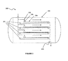
- a configuration 200 which uses multiple conveyer belts 201.
- a key advantage of multiple belts 201 within the same vacuum chamber 202 is increased production rates.
- the chamber 202 includes four belts 201 stacked vertically, each belt 201 being approximately 1.2 metres wide and 12 metres long. It is envisaged that such an arrangement will be able to produce up to 1 tonne of dry material 203 per day.
- a monolayer 204 of frozen portion is formed on each belt 201 using multiple inlet nozzles 205 spraying a cone pattern 206 onto the belt 201. In the embodiment shown, one nozzle 205 is used per belt 201. The monolayer 204 moves along the belts 201 and is collected as a dry material 203.
Landscapes
- Chemical & Material Sciences (AREA)
- Engineering & Computer Science (AREA)
- Life Sciences & Earth Sciences (AREA)
- Chemical Kinetics & Catalysis (AREA)
- Polymers & Plastics (AREA)
- Food Science & Technology (AREA)
- Zoology (AREA)
- Organic Chemistry (AREA)
- Wood Science & Technology (AREA)
- Health & Medical Sciences (AREA)
- Molecular Biology (AREA)
- Mechanical Engineering (AREA)
- General Engineering & Computer Science (AREA)
- Drying Of Solid Materials (AREA)
- Freezing, Cooling And Drying Of Foods (AREA)
Description
- The invention relates to improvements in spray freeze drying,
- Spray freeze drying is discussed in the applicant's co-pending patent,
NZ 529594/529595 WO 2005/105253 ). As mentioned in these specifications, freeze drying materials is well known in the art, for example to remove an aqueous component from a solid suspension leaving a dry solid which may have various uses such as for forming tablets and capsules. - For example,
US 2002/050072 A1 describes a method for obtaining a freeze-dried powder product via various process steps, and associated apparatus for carrying out the method, including one embodiment in which a liquid material is distributively fed from the upper surface side of a shell, which is connected and joined to an outer cylinder further joined to a vacuum pump and a trapping chamber which maintains the interior of the shell in the vacuum condition, by sequentially spraying the liquid material in its atomized form from a plurality of spray nozzles provided on the lower surface side of a distributor disposed in the outer cylinder and connected with a pipeline leading to the tank of liquid material, to thereby spray the liquid material onto the inner wall surface of each of a plurality of tubes which are uprightly provided within the shell in a juxtaposed relationship. The spraying of the liquid material against the inner wall surface of each of the tubes in the shell is done by disposing spray nozzle pipes of a small diameter at the axial center position of each of the tubes and by perforating a multitude of atomizing nozzles in the cylindrical wall of the spray nozzle pipes to thereby connect the upper end of each of the atomizing nozzle pipes with the distributor disposed above the shell, and to thereby spray the liquid material onto the inner wall surface of each of the tubes from this nozzle pipe, which may advantageously be made movable in the up-and-down direction, or in the rotational direction, of the shell. In the applicants co-pending patent, methods and apparatus are described to produce a dried solid from a freeze dryer whereby the solid may be produced on a continuous basis. A key improvement in the previous apparatus and methods was to spray the inlet material and subsequent collection on a conveyed collection surface. - Thus,
WO 2005/105253 describes a method of drying or concentrating a liquid substance having solid particles in suspension or a substance dissolved therein comprising the steps of: holding a chamber at a temperature and pressure below the triple-point of the liquid substance, injecting and/or atomising the liquid substance into the chamber to generate a frozen liquid substance portion ("FLS portion") and a first evaporated liquid substance portion ("FEL portion"), collecting the FLS portion as a layer on a surface, and conveying the collected FLS portion on the surface, wherein the surface conveys the collected FLS portion at a rate which controls the thickness of the layer of collected FLS on the surface. Atomisation of the liquid substance may be induced by a variety of feed devices such as, single-liquid nozzle (pressure type), two-liquid nozzle (pneumatic type), centrifugal (spinning disc), ultrasonic nozzles and various other rotary atomisers and air atomisation techniques may be employed. - Further improvements on the methods and apparatus disclosed in the co-pending patent applications are now disclosed.
- It is an object of the present invention to at least to provide the public with a useful choice.
- No admission is made that any reference including any patents or patent applications cited in this specification constitutes prior art. The discussion of the references states what their authors assert, and the applicants reserve the right to challenge the accuracy and pertinency of the cited documents. It will be clearly understood that, although a number of prior art publications are referred to herein, this reference does not constitute an admission that any of these documents form part of the common general knowledge in the art, in New Zealand or in any other country.
- It is acknowledged that the term 'comprise' may, under varying jurisdictions, be attributed with either an exclusive or an inclusive meaning. For the purpose of this specification, and unless otherwise noted, the term 'comprise' shall have an inclusive meaning - i.e. that it will be taken to mean an inclusion of not only the listed components it directly references, but also other non-specified components or elements. This rationale will also be used when the term 'comprised' or 'comprising' is used in relation to one or more steps in a method or process.
- Further aspects and advantages of the present invention will become apparent from the ensuing description which is given by way of example only.
- According to a first aspect of the present invention there is provided an apparatus for drying or concentrating a raw material which at ambient conditions has a solid and aqueous portion including:
- (a) a chamber and a chamber pressure reduction device; and,
- (b) at least one inlet nozzle through which the raw material is injected into the chamber;
- (c) at least one collection surface which collects a frozen portion of the raw material; and,
- In one embodiment, the frozen portion is collected on at least one collection surface and accumulated as a layer on the surface or surfaces, the thickness of which is controlled by at least one parameter selected from:
- i. the raw material inlet flow rate;
- ii. use of positive inlet pressure;
- iii. inlet nozzle size and configuration; and/or,
- iv. the distance between the inlet nozzle outlet and the collection surface.
- According to a further aspect of the present invention there is provided a method of drying or concentrating a raw material which at ambient conditions has a solid and an aqueous portion by the steps of:
- (a) holding a chamber at a temperature and pressure below the triple-point of the aqueous portion of the raw material;
- (b) injecting the raw material into the chamber from at least one inlet nozzle to generate a frozen portion and a first evaporated portion;
- (c) collecting the frozen portion as a layer on at least one collection surface;
- (d) conveying the collected frozen portion on the collection surface or surfaces; and,
- i. the raw material inlet flow rate;
- ii. use of positive inlet pressure;
- iii. inlet nozzle size and configuration; and/or,
- iv. the distance between the inlet nozzle outlet and the collection surface,
- Preferably, the thickness of the layer collected on the collection surface is also controlled by the rate of conveyance of the collection surface.
- The inventors have found that several critical features are involved in forming a frozen layer on the collection surface beyond just the rate of conveyance. Forming a layer that is smooth, continuous and fine (termed for the purposes of this specification as a 'monolayer') is critical in achieving a uniformly dried product from the dryer. Preferably, the frozen layer on the collection surface is characterised by being smooth, continuous and a fine width. For the purposes of this specification, the term 'fine width' refers to the layer being less than 10mm in width. In preferred embodiments, the width is less than 5mm.
- For the purposes of this disclosure and ease of reading, the collection surface may be referred to interchangeably as a conveyer belt. This should not be seen as limiting as other conveying methods such as those described in
NZ 529594/529595 - Preferably, the raw material is a solid suspended in or dissolved in the aqueous portion. More preferably, the raw material includes up to 50% solid material. Still more preferably, the raw material includes less than 30% solid material. As should be appreciated by those skilled in the art, these parameters equate to various dairy products such as milk to be dried, nutraceutical extracts and other products. It is envisaged that the raw material could also be a frozen solid material containing an aqueous portion. For example, the dryer assembly may be used for continuous drying of solid materials such as frozen vegetables. Further reference will be made to drying of solid / aqueous mixtures however this should not be seen as limiting.
- Preferably, the raw material inlet flow rate is tailored to the collection surface size at a ratio of 1 kg/hour of raw material per 0.25 to 1.5 metres of collection surface width. As noted above, a key parameter found to achieve formation of a monolayer on the collection surface is use of an inlet rate tailored to the conveyer belt width. In one embodiment, the inlet rate is approximately 10kg/hour of raw material to be dried on an approximately 0.5 m wide and 9 metre long conveyer belt. If the rate is increased above this level, product collected on the belt may be too thick to dry sufficiently and may also not fully freeze on formation of a monolayer resulting in small explosions as described further below.
- A further key parameter found by the inventors is that the raw material is pumped into the vacuum chamber using a positive pressure rather than relying on the vacuum in the chamber alone to drive the dispersion of raw material into the chamber. In preferred embodiments, the back pressure ranges from approximately 0.138 to 0.276 MPa (20 to 40psi). One problem noted by having insufficient back pressure is that discrete snow-like crystals are deposited on the conveyer belt surface rather than formation of a monolayer. The crystals also tend to blow around the chamber, not staying in one position (a monolayer) during drying.
- The inventors have found that, once vacuum pressure and inlet pressure are stabilised, the inlet nozzle applies the raw material as a flat sheet monolayer on a continuous basis for hours at a time without need to adjust any parameters.
- In preferred embodiments as described in
NZ 529594/529595 - A further key parameter in achieving the desired size of particle as well as achieving a monolayer of material on the conveyer belt is nozzle selection. Preferably, the inlet nozzle or nozzles are selected based on injecting sufficient quantities of raw material such that:
- (i) initial sublimation of first evaporated portion can occur;
- (ii) the frozen portion transfers to a solid; and
- (iii) the nozzle size is tailored to the raw material viscosity.
- It is the inventors' experience that atomiser nozzle choice is a critical variable. Preferred nozzle types are those that are relatively small and spray a half cone shaped arrangement. Full cone nozzle types may be used but the inlet flow of raw material must then be carefully regulated to ensure that liquid material does not become frozen under a solid cap on the conveyer belt resulting in sublimation and small explosions (see below). Nozzles are preferably sized to account for material viscosity. For example, materials with higher viscosity require larger nozzle sizes in order to ensure a smooth flow and full atomisation of the raw material.
- A yet further key parameter in the inventors experience is the distance between the inlet nozzle and the collection surface. In preferred embodiments, the distance between the inlet nozzle or nozzles and the collection surface or surfaces varies from between 70 and 120mm. In a particularly preferred embodiment, this distance is approximately 90mm, although, it should be appreciated that this may vary depending on at least the raw material and nozzle configuration.
- The inlet nozzle or nozzles move across the collection surface during operation. The inlet nozzle is attached to a pivoting arm which is attached to an actuator which moves the arm through a pre-set course such that the inlet nozzle sprays an arc of raw material onto the collection surface. For the purposes of this specification, this arc pivot is referred to as a 'swinging arm'. In one embodiment, a swinging arm is used to spray raw material onto a conveyer belt where the arc tracks the inlet nozzle across the width of the belt. In an alternative embodiment, multiple swinging arms are used on one belt to cover a belt surface and the swinging arms may be arranged in parallel beside each other or in series after each other. Whilst the above description is made with respect to a pivot producing a spray arc, other moving nozzle patterns are envisaged such as straight line back and forth patterns across the belt. An arc pattern should not be seen as limiting.
- Preferably, the vacuum pressure in the chamber remains at an approximately steady level of less than or equal to 4.0 mbar. The inventors have found that the vacuum chamber must operate at a pressure below the triple point of the aqueous portion of the raw material to be separated from the solid material. In preferred embodiments, this pressure for water containing raw materials ranges from approximately 0.3 to 4.0 mbar.
- In addition to the parameters discussed above, vacuum pressure has been found to be a key variable. For example, if the vacuum pressure is greater than 4 mbar, the raw material tends to fully freeze only after being collected on the conveyer belt. This is not desirable as uneven layer formation results and even small explosions may occur from trapped liquid under an outer solid cap subliming and flashing off breaking open the cap. Opportunities for product deterioration may also result from higher vacuum pressures delaying freezing.
- A further factor found important by the inventors has been that it is important that the vacuum pressure remain at an approximately steady level and if changing, that the change occurs at a relatively slow rate. In preferred embodiments, any fluctuations in pressure in the vacuum chamber are less than 0.5 to 1.5 mbar above or below the set vacuum pressure. Fluctuations greater than this, particularly if they occur quickly, may result in uneven layering and potentially sublimation problems such as small explosions noted above.
- In a further embodiment, particle size reducing devices may also be incorporated into the design of the dryer. In one preferred embodiment, the vacuum chamber includes a granulator to reduce the product particle size as the dried material leaves the conveyer belt. Preferably, the granulator is a rotor and cutter house configuration.
- Preferably, the collection surface or surfaces is or are conveyer belt(s).
- Preferably, the belt or belts include at least one inlet nozzle per belt.
- In one embodiment, the raw material is injected onto a first upper most conveyer belt and through gravity, the material drops onto at least one further conveyer belt located underneath the first belt until being collected after being dried.
- In preferred embodiments, the dryer includes at least two condensing chambers including coils onto which vaporised water or other aqueous substances condense so that in use, one chamber may be used in operation and the other chamber isolated from the vacuum chamber to allow alternate defrosting. It should be appreciated that by having two or more chambers, one chamber may be used in operation and the other chamber isolated from the vacuum chamber to allow alternate defrosting without disrupting processing.
- According to a further aspect of the present invention there is provided a dried product produced using the apparatus substantially as described above.
- According to a further aspect of the present invention there is provided a dried product produced by the method substantially as described above.
- From the above description it should be appreciated that there are provided improved methods and apparatus for drying a raw material having a solid and aqueous portion. Key advantages from the method and apparatus include:
- small particle size and formation of a smooth continuous and fine layer (monolayer) on the collection surface resulting in a reduction in energy required compared to traditional batch drying methods;
- final product moisture content of approximately 1-2%, comparable to other drying methods;
- continuous processing;
- reduced labour costs from use of the method and apparatus due to greater automation and removal of steps such as manual loading and unloading of the dryer; and,
- reduced cleaning required and the ability to clean in place (CIP).
- Further aspects of the present invention will become apparent from the ensuing description which is given by way of example only and with reference to the accompanying drawings in which:
- Figure 1
- shows a diagram of a spray freeze dryer according to one aspect of the present invention;
- Figure 2
- shows a diagram of one swinging arm configuration; and,
- Figure 3
- shows a diagram of one multiple belt configuration in accordance with the present invention.
- Reference is made to the applicant's co-pending patent applications
NZ 529594/529595 WO 2005/105253 for a detailed description of the method and apparatus. Alternative embodiments described above are now further described in more detail below. - Referring to
Figure 1 , an apparatus for drying or concentrating a material having a solid and aqueous portion at ambient conditions is shown. The apparatus includes a spray freeze dryer generally indicated byarrow 1. Thedryer 1 includes a vacuum chamber 2 maintained at a pressure below the triple point of the aqueous portion of the raw material using apump 15. - Raw material 3 is located in a tank T. In this embodiment the raw material contains less than 50% solids dispersed within an aqueous solution.
- The raw material is pumped using
inlet pump 17 viaairlock valves 18A andinlet nozzle 10 into the vacuum chamber 2. Thenozzle 10 disperses the raw material 3 as a fine spray and the evaporatedportions coils 6. - Frozen portion 4 is collected on a conveyer belt 8 as a fine monolayer of frozen material 7. The monolayer 7 is conveyed along the belt 8 and further evaporated
portion heating panels 11 underneath the belt 8. The driedmaterial 12 is collected 18B viaoutlet airlock valve 14. Ascraper device 13 may be used to remove driedmaterial 12 from the belt 8. - The inventors have found that a critical step in achieving a dried
product 12 is the production of a smooth monolayer 7 when the raw material 3 is sprayed into the chamber and collected on the belt 8. - Critical parameters in achieving this monolayer include the rate of conveyance of the belt 8 but also other parameters including the raw material 3 inlet rate; the use of positive pressure from the inlet pump(s) 18A;
inlet nozzle 10 size and configuration; and the distance between theinlet nozzle 10 and conveyer belt 8. - In this example the inlet rate is approximately 10kg/hour of inlet material 3 based on an approximately 9 metre long conveyer belt 8. If the inlet rate is increased above this level, the layer 7 collected on the belt 8 may be too thick to dry sufficiently and may also not fully freeze on forming of a monolayer 7 resulting in small explosions where liquid phase is trapped beneath a solid phase on the monolayer. This liquid phase subsequently boils off and explodes the upper solid layer.
- In the example shown in
Figure 1 , the raw material 3 is pumped into the vacuum chamber 2 frominlet pumps 18A using a back pressure ranging from approximately 0.138 to 0.276 MPa (20 to 40psi). One problem noted by having insufficient back pressure is that discrete snow-like crystals (not shown) are deposited on the conveyer belt surface 7 rather than formation of a monolayer. The crystals also tend to blow around the chamber 2, not staying in one position during drying. - In the example shown in
Figure 1 , theinlet nozzle 10 is selected based on atomising sufficient quantities of raw material 3 to allow initial sublimation; transfer of frozen portion to a solid phase; and, to take into account raw material 3 viscosity. Onepreferred nozzle 10 type is a half cone atomiser which sprays a ring shape pattern. - In the embodiment shown in
Figure 1 , the distance between thenozzle 10 outlet and the conveyor belt 8 is approximately 90mm. - To ensure formation of a smooth, continuous and fine monolayer on the belt 8, the vacuum pressure in the embodiment of
Figure 1 is maintained below 3 mbar. This is done to avoid uneven layer formation results and even small explosions occurring from trapped liquid under an outer solid cap subliming and flashing off breaking open the cap. Fluctuations in pressure are also minimised to assist in avoiding uneven layering and sublimation problems such as small explosions noted above. - The chamber also includes a rotor and cutter house configuration granulator (not shown) inside the vacuum chamber 2, which reduces the particle size of the dried
material 12 before it leaves the vacuum chamber 2. - Referring to
Figure 2 , a swingingarm embodiment 100 is shown whereby thenozzle 101 moves through anarc 102 defined by a pivotingarm 103 over thecollection surface 105. The collection surfaces moves in direction A. Thearm 103 is attached to an actuator (not shown), which moves thearm 103 through a pre-set course such that thenozzle 101 sprays anarc 102 of frozen portion which forms amonolayer 104 on thecollection surface 105. - Referring to
Figure 3 , aconfiguration 200 is shown which usesmultiple conveyer belts 201. A key advantage ofmultiple belts 201 within thesame vacuum chamber 202 is increased production rates. In theembodiment 200 shown inFigure 3 , thechamber 202 includes fourbelts 201 stacked vertically, eachbelt 201 being approximately 1.2 metres wide and 12 metres long. It is envisaged that such an arrangement will be able to produce up to 1 tonne ofdry material 203 per day. Amonolayer 204 of frozen portion is formed on eachbelt 201 usingmultiple inlet nozzles 205 spraying acone pattern 206 onto thebelt 201. In the embodiment shown, onenozzle 205 is used perbelt 201. Themonolayer 204 moves along thebelts 201 and is collected as adry material 203. - In a further arrangement not shown, the condensing coils are located in one or more adjacent chambers. These chambers may be alternately sealed whereby one chamber may be operated and the other chamber isolated from the vacuum chamber to allow alternate defrosting and cleaning without disrupting processing.
- From the above description it should be appreciated that there is provided improved methods and apparatus for drying a solid material containing an aqueous component with improved identification of critical parameters to assist in forming a smooth, continuous and fine layer on the collection surface. The fine layer results in effective drying.
- Aspects of the present invention have been described by way of example.
wherein the frozen portion is collected on at least one collection surface and accumulated as a layer on the surface or surfaces and,
characterised in that the inlet nozzle or nozzles are attached to a pivoting arm or arms which are attached to at least one actuator that moves the arm or arms through a pre-set course such that the inlet nozzle or nozzles move across the collection surface during operation and spray an arc or arcs of raw material onto the collection surface.
Claims (14)
- An apparatus for drying or concentrating a raw material which at ambient conditions has a solid and aqueous portion including:(a) a chamber (2, 202) and a chamber pressure reduction device (15); and,(b) at least one inlet nozzle (10, 101, 205) through which the raw material (3) is injected into the chamber;(c) at least one collection surface (8, 105, 201) which collects a frozen portion (4) of the raw material: and,
wherein the pressure reduction device maintains the chamber at a pressure below at least the triple-point pressure of the aqueous portion of the raw material, to cause the injected raw material to separate into a frozen portion and a first evaporated portion (5A, 5B);
wherein the frozen portion is collected on at least one collection surface and accumulated as a layer (7, 204) on the surface or surfaces; and, characterised in that the inlet nozzle or nozzles are attached to a pivoting arm or arms (103) which are attached to at least one actuator that moves the arm or arms through a pre-set course such that the inlet nozzle or nozzles move across the collection surface during operation and spray an arc or arcs (102) of raw material onto the collection surface. - The apparatus as claimed in claim 1 wherein the apparatus is for drying or concentrating a raw material (3) which is a solid suspended in or dissolved in the aqueous portion.
- The apparatus as claimed in any one of the above claims wherein the raw material (3) is injected into the vacuum chamber (2, 202) using a nozzle or nozzles (10, 101, 205) that atomise the raw material into particles.
- The apparatus as claimed in any one of the above claims wherein the inlet nozzle or nozzles (10, 101, 205) are selected based on injecting sufficient quantities of raw material such that:a) initial sublimation of first evaporated portion can occur;b) the frozen portion transfers to a solid; andc) the nozzle size is tailored to the raw material viscosity.
- The apparatus as claimed in any one of the above claims where in the collection surface or surfaces (8, 105, 201) is or are conveyer belt(s).
- The apparatus as claimed in claim 5 wherein the chamber (2, 202) includes two or more conveyor belts (8, 105, 201), stacked in a parallel arrangement within the vacuum chamber (2, 202).
- The apparatus as claimed in claim 5 or claim 6 wherein the belt or belts (8, 105, 201) include at least one inlet nozzle (10, 101, 205) per belt.
- A method of drying or concentrating a raw material which at ambient conditions has a solid and an aqueous portion by the steps of:(a) holding a chamber (2, 202) at a temperature and pressure below the triple-point of the aqueous portion of the raw material;(b) injecting the raw material (3) into the chamber from at least one inlet nozzle (10, 101, 205) to generate a frozen portion (4) and a first evaporated portion (5A, 5B);(c) collecting the frozen portion as a layer (7, 204) on at least one collection surface;(d) conveying the collected frozen portion on the collection surface or surfaces (8, 105, 201); and,
wherein the thickness of the frozen portion on the collection surface is controlled by at least one parameter selected from:i. the raw material inlet flow rate;ii. use of positive inlet pressure;iii. inlet nozzle size and configuration; and/or,iv. the distance between the inlet nozzle outlet and the collection surface,characterised in that the inlet nozzle or nozzles are attached to a pivoting arm or arms (103) which are attached to at least one actuator that moves the arm or arms through a pre-set course such that the inlet nozzle or nozzles move across the collection surface during operation and spray an arc or arcs (102) of raw material onto the collection surface. - The method as claimed in claim 8 wherein the raw material (3) is a solid suspended in or dissolved in the aqueous portion.
- The method as claimed in claim 8 or 9 wherein the raw material (3) is injected into the vacuum chamber (2, 202) using a nozzle or nozzles (10, 101, 205) that atomise the raw material into particles.
- The method as claimed in any one of claims 8 to 10 wherein the inlet nozzle or nozzles (10, 101, 205) are selected based on injecting sufficient quantities of raw material (3) such that:a) initial sublimation of first evaporated portion can occur;b) the frozen portion transfers to a solid; andc) the nozzle size is tailored to the raw material viscosity.
- The method as claimed in any one of claims 8 to 11 wherein the collection surface or surfaces is or are conveyer belt(s) (8, 105, 201).
- The method as claimed in claim 12 wherein the chamber includes two or more conveyer belts (8, 105, 201), stacked in a parallel arrangement within the vacuum chamber (2, 202).
- The method as claimed in claim 12 or claim 13 wherein the belt or belts (8, 105, 201) include at least one inlet nozzle (10, 101, 205) per belt.
Applications Claiming Priority (2)
| Application Number | Priority Date | Filing Date | Title |
|---|---|---|---|
| NZ550563A NZ550563A (en) | 2006-10-16 | 2006-10-16 | Improvements in spray freeze drying |
| PCT/NZ2007/000305 WO2008048115A2 (en) | 2006-10-16 | 2007-10-16 | Improvements in spray freeze drying |
Publications (3)
| Publication Number | Publication Date |
|---|---|
| EP2074366A2 EP2074366A2 (en) | 2009-07-01 |
| EP2074366A4 EP2074366A4 (en) | 2014-05-21 |
| EP2074366B1 true EP2074366B1 (en) | 2016-01-06 |
Family
ID=39314477
Family Applications (1)
| Application Number | Title | Priority Date | Filing Date |
|---|---|---|---|
| EP07860950.0A Not-in-force EP2074366B1 (en) | 2006-10-16 | 2007-10-16 | Improvements in spray freeze drying |
Country Status (6)
| Country | Link |
|---|---|
| US (1) | US20110016742A1 (en) |
| EP (1) | EP2074366B1 (en) |
| AU (1) | AU2007313546B2 (en) |
| DK (1) | DK2074366T3 (en) |
| NZ (1) | NZ550563A (en) |
| WO (1) | WO2008048115A2 (en) |
Families Citing this family (11)
| Publication number | Priority date | Publication date | Assignee | Title |
|---|---|---|---|---|
| US20110113644A1 (en) * | 2008-07-10 | 2011-05-19 | Ulvac, Inc. | Freeze-drying apparatus and freeze-drying method |
| US9102081B2 (en) * | 2011-11-21 | 2015-08-11 | Dr. Hielscher Gmbh | Method and apparatus for generating particles |
| WO2013139384A1 (en) | 2012-03-21 | 2013-09-26 | Dorkoosh, Farid Abedin | Freezing of aerosolized solutions (fas): a system for continuous particle production |
| US20150227586A1 (en) * | 2014-02-07 | 2015-08-13 | Futurewei Technologies, Inc. | Methods and Systems for Dynamically Allocating Resources and Tasks Among Database Work Agents in an SMP Environment |
| WO2019094540A1 (en) * | 2017-11-09 | 2019-05-16 | Blh Ecology Concepts, Llc | Process to produce nanoparticles |
| WO2019235036A1 (en) * | 2018-06-08 | 2019-12-12 | 株式会社アルバック | Freeze vacuum drying device and freeze vacuum drying method |
| WO2021207159A1 (en) * | 2020-04-08 | 2021-10-14 | Oregon Drytech, Llc | Drying apparatus |
| WO2022030055A1 (en) * | 2020-08-07 | 2022-02-10 | 株式会社アルバック | Vacuum freeze-drying method, spray nozzle for vacuum freeze-drying device, and vacuum freeze-drying device |
| JP2022064439A (en) * | 2020-10-14 | 2022-04-26 | 株式会社アルバック | Freeze-drying device |
| CA3173146C (en) * | 2020-11-16 | 2023-10-31 | Joel Peter LENNON-MEYER | Continuous throughput lyophilizer/powder filler within a sterile boundary |
| CN113289549A (en) * | 2021-05-17 | 2021-08-24 | 西安工业大学 | Spray freeze drying instrument capable of controlling particle size of nano powder |
Family Cites Families (10)
| Publication number | Priority date | Publication date | Assignee | Title |
|---|---|---|---|---|
| US2515098A (en) * | 1945-08-01 | 1950-07-11 | Chain Belt Co | Continuous low-temperature dehydration |
| US3232068A (en) * | 1964-04-17 | 1966-02-01 | Fmc Corp | Loading freeze dryers |
| DE1729463A1 (en) * | 1967-07-07 | 1971-08-05 | Walter Schicketanz | Device for transferring a liquid into a room with a lower pressure than outside it, especially for freeze-drying systems |
| US3740860A (en) * | 1972-07-31 | 1973-06-26 | Smitherm Industries | Freeze drying method and apparatus |
| US4033048A (en) * | 1976-01-12 | 1977-07-05 | Clayton Van Ike | Freeze drying apparatus |
| DE2659546A1 (en) * | 1976-12-30 | 1978-07-13 | Boehringer Mannheim Gmbh | METHOD FOR PRODUCING FROZEN GRANULES |
| US4433640A (en) * | 1980-11-28 | 1984-02-28 | Circle Machine Co., Inc. | Rotary sprayers for applying uniform coats to conveyor supported work |
| JP3639783B2 (en) | 2000-10-30 | 2005-04-20 | 共和真空技術株式会社 | Freeze-drying method and freeze-drying equipment for food and medicine |
| US6931888B2 (en) * | 2003-02-07 | 2005-08-23 | Ferro Corporation | Lyophilization method and apparatus for producing particles |
| MXPA06012614A (en) * | 2004-05-01 | 2007-07-18 | Agres Ltd | Drying process and apparatus. |
-
2006
- 2006-10-16 NZ NZ550563A patent/NZ550563A/en not_active IP Right Cessation
-
2007
- 2007-10-16 US US12/445,797 patent/US20110016742A1/en not_active Abandoned
- 2007-10-16 EP EP07860950.0A patent/EP2074366B1/en not_active Not-in-force
- 2007-10-16 WO PCT/NZ2007/000305 patent/WO2008048115A2/en not_active Ceased
- 2007-10-16 DK DK07860950.0T patent/DK2074366T3/en active
- 2007-10-16 AU AU2007313546A patent/AU2007313546B2/en not_active Ceased
Also Published As
| Publication number | Publication date |
|---|---|
| DK2074366T3 (en) | 2016-04-11 |
| NZ550563A (en) | 2009-01-31 |
| WO2008048115A3 (en) | 2008-06-26 |
| EP2074366A4 (en) | 2014-05-21 |
| EP2074366A2 (en) | 2009-07-01 |
| AU2007313546B2 (en) | 2011-07-21 |
| AU2007313546A1 (en) | 2008-04-24 |
| AU2007313546A2 (en) | 2009-05-21 |
| WO2008048115A2 (en) | 2008-04-24 |
| US20110016742A1 (en) | 2011-01-27 |
Similar Documents
| Publication | Publication Date | Title |
|---|---|---|
| AU2007313546B2 (en) | Improvements in spray freeze drying | |
| EP2999933B1 (en) | Process for drying and powderizing functional foods, nutraceuticals, and natural health ingredients | |
| US7007406B2 (en) | Powder formation by atmospheric spray-freeze drying | |
| US8322046B2 (en) | Powder formation by atmospheric spray-freeze drying | |
| EP0961646A2 (en) | Spray drying method and apparatus and cleaning method for such an apparatus | |
| AU574268B2 (en) | Process for converting a thermoplastic polymer into spheroidal agglomerated granules | |
| JP2004232883A (en) | Spray-type vacuum freeze dryer | |
| US20090134250A1 (en) | Method and device for the production and/or conditioning of powdered material | |
| CN113289549A (en) | Spray freeze drying instrument capable of controlling particle size of nano powder | |
| CN101410383B (en) | A process for drying melamine | |
| US20090220676A1 (en) | Multi-stage coating device for moulded bodies | |
| KR100848014B1 (en) | Granulator of liquid material | |
| CN103238917B (en) | Device for adding liquid auxiliary materials into tobacco with high uniformity and auxiliary material adding method | |
| CN112168698B (en) | Coating machine and multi-enzyme tablet production process applying same | |
| RU2328338C1 (en) | Method of granulated product preparation and drum granulator | |
| JP7826242B2 (en) | Frozen particle production equipment | |
| RU2100302C1 (en) | Granular material capsulating method | |
| CN203302325U (en) | Device for adding liquid auxiliary materials into tobacco with high uniformity | |
| CA2450779C (en) | Powder formation by atmospheric spray-freeze drying | |
| Shinde et al. | Spray Drying: A Promising Technique to Enhance Solubility | |
| CN117983112A (en) | A graphene production device and method with less than three layers and an ultrasonic stirring feeding device | |
| RU2353351C1 (en) | Method of temperature sensitive medicine recovery from fluid medium and related plant therefor | |
| RU2302927C1 (en) | Method for producing finely dispersed metal powders | |
| CN207259405U (en) | A kind of new-type fertilizer injection system | |
| CN119803038A (en) | Vacuum belt dryer for solid and liquid |
Legal Events
| Date | Code | Title | Description |
|---|---|---|---|
| PUAI | Public reference made under article 153(3) epc to a published international application that has entered the european phase |
Free format text: ORIGINAL CODE: 0009012 |
|
| 17P | Request for examination filed |
Effective date: 20090331 |
|
| AK | Designated contracting states |
Kind code of ref document: A2 Designated state(s): AT BE BG CH CY CZ DE DK EE ES FI FR GB GR HU IE IS IT LI LT LU LV MC MT NL PL PT RO SE SI SK TR |
|
| AX | Request for extension of the european patent |
Extension state: AL BA HR MK RS |
|
| DAX | Request for extension of the european patent (deleted) | ||
| A4 | Supplementary search report drawn up and despatched |
Effective date: 20140417 |
|
| RIC1 | Information provided on ipc code assigned before grant |
Ipc: A23L 3/44 20060101ALI20140411BHEP Ipc: F26B 5/06 20060101AFI20140411BHEP Ipc: B01D 1/18 20060101ALI20140411BHEP Ipc: B01J 2/26 20060101ALI20140411BHEP |
|
| 17Q | First examination report despatched |
Effective date: 20140918 |
|
| GRAP | Despatch of communication of intention to grant a patent |
Free format text: ORIGINAL CODE: EPIDOSNIGR1 |
|
| INTG | Intention to grant announced |
Effective date: 20150612 |
|
| GRAS | Grant fee paid |
Free format text: ORIGINAL CODE: EPIDOSNIGR3 |
|
| GRAP | Despatch of communication of intention to grant a patent |
Free format text: ORIGINAL CODE: EPIDOSNIGR1 |
|
| GRAA | (expected) grant |
Free format text: ORIGINAL CODE: 0009210 |
|
| INTG | Intention to grant announced |
Effective date: 20151110 |
|
| AK | Designated contracting states |
Kind code of ref document: B1 Designated state(s): AT BE BG CH CY CZ DE DK EE ES FI FR GB GR HU IE IS IT LI LT LU LV MC MT NL PL PT RO SE SI SK TR |
|
| REG | Reference to a national code |
Ref country code: GB Ref legal event code: FG4D |
|
| REG | Reference to a national code |
Ref country code: CH Ref legal event code: EP |
|
| REG | Reference to a national code |
Ref country code: IE Ref legal event code: FG4D |
|
| REG | Reference to a national code |
Ref country code: AT Ref legal event code: REF Ref document number: 769195 Country of ref document: AT Kind code of ref document: T Effective date: 20160215 |
|
| REG | Reference to a national code |
Ref country code: DE Ref legal event code: R096 Ref document number: 602007044507 Country of ref document: DE |
|
| REG | Reference to a national code |
Ref country code: DK Ref legal event code: T3 Effective date: 20160404 |
|
| REG | Reference to a national code |
Ref country code: LT Ref legal event code: MG4D |
|
| REG | Reference to a national code |
Ref country code: NL Ref legal event code: MP Effective date: 20160106 |
|
| REG | Reference to a national code |
Ref country code: AT Ref legal event code: MK05 Ref document number: 769195 Country of ref document: AT Kind code of ref document: T Effective date: 20160106 |
|
| PG25 | Lapsed in a contracting state [announced via postgrant information from national office to epo] |
Ref country code: NL Free format text: LAPSE BECAUSE OF FAILURE TO SUBMIT A TRANSLATION OF THE DESCRIPTION OR TO PAY THE FEE WITHIN THE PRESCRIBED TIME-LIMIT Effective date: 20160106 |
|
| PG25 | Lapsed in a contracting state [announced via postgrant information from national office to epo] |
Ref country code: FI Free format text: LAPSE BECAUSE OF FAILURE TO SUBMIT A TRANSLATION OF THE DESCRIPTION OR TO PAY THE FEE WITHIN THE PRESCRIBED TIME-LIMIT Effective date: 20160106 Ref country code: GR Free format text: LAPSE BECAUSE OF FAILURE TO SUBMIT A TRANSLATION OF THE DESCRIPTION OR TO PAY THE FEE WITHIN THE PRESCRIBED TIME-LIMIT Effective date: 20160407 Ref country code: IT Free format text: LAPSE BECAUSE OF FAILURE TO SUBMIT A TRANSLATION OF THE DESCRIPTION OR TO PAY THE FEE WITHIN THE PRESCRIBED TIME-LIMIT Effective date: 20160106 Ref country code: ES Free format text: LAPSE BECAUSE OF FAILURE TO SUBMIT A TRANSLATION OF THE DESCRIPTION OR TO PAY THE FEE WITHIN THE PRESCRIBED TIME-LIMIT Effective date: 20160106 |
|
| PG25 | Lapsed in a contracting state [announced via postgrant information from national office to epo] |
Ref country code: PL Free format text: LAPSE BECAUSE OF FAILURE TO SUBMIT A TRANSLATION OF THE DESCRIPTION OR TO PAY THE FEE WITHIN THE PRESCRIBED TIME-LIMIT Effective date: 20160106 Ref country code: LV Free format text: LAPSE BECAUSE OF FAILURE TO SUBMIT A TRANSLATION OF THE DESCRIPTION OR TO PAY THE FEE WITHIN THE PRESCRIBED TIME-LIMIT Effective date: 20160106 Ref country code: IS Free format text: LAPSE BECAUSE OF FAILURE TO SUBMIT A TRANSLATION OF THE DESCRIPTION OR TO PAY THE FEE WITHIN THE PRESCRIBED TIME-LIMIT Effective date: 20160506 Ref country code: SE Free format text: LAPSE BECAUSE OF FAILURE TO SUBMIT A TRANSLATION OF THE DESCRIPTION OR TO PAY THE FEE WITHIN THE PRESCRIBED TIME-LIMIT Effective date: 20160106 Ref country code: AT Free format text: LAPSE BECAUSE OF FAILURE TO SUBMIT A TRANSLATION OF THE DESCRIPTION OR TO PAY THE FEE WITHIN THE PRESCRIBED TIME-LIMIT Effective date: 20160106 Ref country code: LT Free format text: LAPSE BECAUSE OF FAILURE TO SUBMIT A TRANSLATION OF THE DESCRIPTION OR TO PAY THE FEE WITHIN THE PRESCRIBED TIME-LIMIT Effective date: 20160106 Ref country code: PT Free format text: LAPSE BECAUSE OF FAILURE TO SUBMIT A TRANSLATION OF THE DESCRIPTION OR TO PAY THE FEE WITHIN THE PRESCRIBED TIME-LIMIT Effective date: 20160506 |
|
| REG | Reference to a national code |
Ref country code: DE Ref legal event code: R097 Ref document number: 602007044507 Country of ref document: DE |
|
| PG25 | Lapsed in a contracting state [announced via postgrant information from national office to epo] |
Ref country code: EE Free format text: LAPSE BECAUSE OF FAILURE TO SUBMIT A TRANSLATION OF THE DESCRIPTION OR TO PAY THE FEE WITHIN THE PRESCRIBED TIME-LIMIT Effective date: 20160106 |
|
| PLBE | No opposition filed within time limit |
Free format text: ORIGINAL CODE: 0009261 |
|
| STAA | Information on the status of an ep patent application or granted ep patent |
Free format text: STATUS: NO OPPOSITION FILED WITHIN TIME LIMIT |
|
| PG25 | Lapsed in a contracting state [announced via postgrant information from national office to epo] |
Ref country code: CZ Free format text: LAPSE BECAUSE OF FAILURE TO SUBMIT A TRANSLATION OF THE DESCRIPTION OR TO PAY THE FEE WITHIN THE PRESCRIBED TIME-LIMIT Effective date: 20160106 Ref country code: SK Free format text: LAPSE BECAUSE OF FAILURE TO SUBMIT A TRANSLATION OF THE DESCRIPTION OR TO PAY THE FEE WITHIN THE PRESCRIBED TIME-LIMIT Effective date: 20160106 Ref country code: RO Free format text: LAPSE BECAUSE OF FAILURE TO SUBMIT A TRANSLATION OF THE DESCRIPTION OR TO PAY THE FEE WITHIN THE PRESCRIBED TIME-LIMIT Effective date: 20160106 |
|
| 26N | No opposition filed |
Effective date: 20161007 |
|
| PG25 | Lapsed in a contracting state [announced via postgrant information from national office to epo] |
Ref country code: BE Free format text: LAPSE BECAUSE OF FAILURE TO SUBMIT A TRANSLATION OF THE DESCRIPTION OR TO PAY THE FEE WITHIN THE PRESCRIBED TIME-LIMIT Effective date: 20160106 |
|
| PG25 | Lapsed in a contracting state [announced via postgrant information from national office to epo] |
Ref country code: BG Free format text: LAPSE BECAUSE OF FAILURE TO SUBMIT A TRANSLATION OF THE DESCRIPTION OR TO PAY THE FEE WITHIN THE PRESCRIBED TIME-LIMIT Effective date: 20160406 Ref country code: SI Free format text: LAPSE BECAUSE OF FAILURE TO SUBMIT A TRANSLATION OF THE DESCRIPTION OR TO PAY THE FEE WITHIN THE PRESCRIBED TIME-LIMIT Effective date: 20160106 |
|
| REG | Reference to a national code |
Ref country code: DE Ref legal event code: R119 Ref document number: 602007044507 Country of ref document: DE |
|
| REG | Reference to a national code |
Ref country code: DK Ref legal event code: EBP Effective date: 20161031 |
|
| REG | Reference to a national code |
Ref country code: CH Ref legal event code: PL |
|
| GBPC | Gb: european patent ceased through non-payment of renewal fee |
Effective date: 20161016 |
|
| REG | Reference to a national code |
Ref country code: IE Ref legal event code: MM4A |
|
| REG | Reference to a national code |
Ref country code: FR Ref legal event code: ST Effective date: 20170630 |
|
| PG25 | Lapsed in a contracting state [announced via postgrant information from national office to epo] |
Ref country code: DE Free format text: LAPSE BECAUSE OF NON-PAYMENT OF DUE FEES Effective date: 20170503 Ref country code: FR Free format text: LAPSE BECAUSE OF NON-PAYMENT OF DUE FEES Effective date: 20161102 Ref country code: GB Free format text: LAPSE BECAUSE OF NON-PAYMENT OF DUE FEES Effective date: 20161016 Ref country code: LI Free format text: LAPSE BECAUSE OF NON-PAYMENT OF DUE FEES Effective date: 20161031 Ref country code: CH Free format text: LAPSE BECAUSE OF NON-PAYMENT OF DUE FEES Effective date: 20161031 |
|
| PG25 | Lapsed in a contracting state [announced via postgrant information from national office to epo] |
Ref country code: LU Free format text: LAPSE BECAUSE OF NON-PAYMENT OF DUE FEES Effective date: 20161016 |
|
| PG25 | Lapsed in a contracting state [announced via postgrant information from national office to epo] |
Ref country code: IE Free format text: LAPSE BECAUSE OF NON-PAYMENT OF DUE FEES Effective date: 20161016 Ref country code: DK Free format text: LAPSE BECAUSE OF NON-PAYMENT OF DUE FEES Effective date: 20161031 |
|
| PG25 | Lapsed in a contracting state [announced via postgrant information from national office to epo] |
Ref country code: HU Free format text: LAPSE BECAUSE OF FAILURE TO SUBMIT A TRANSLATION OF THE DESCRIPTION OR TO PAY THE FEE WITHIN THE PRESCRIBED TIME-LIMIT; INVALID AB INITIO Effective date: 20071016 Ref country code: CY Free format text: LAPSE BECAUSE OF FAILURE TO SUBMIT A TRANSLATION OF THE DESCRIPTION OR TO PAY THE FEE WITHIN THE PRESCRIBED TIME-LIMIT Effective date: 20160106 |
|
| PG25 | Lapsed in a contracting state [announced via postgrant information from national office to epo] |
Ref country code: MT Free format text: LAPSE BECAUSE OF NON-PAYMENT OF DUE FEES Effective date: 20161031 Ref country code: MC Free format text: LAPSE BECAUSE OF FAILURE TO SUBMIT A TRANSLATION OF THE DESCRIPTION OR TO PAY THE FEE WITHIN THE PRESCRIBED TIME-LIMIT Effective date: 20160106 Ref country code: TR Free format text: LAPSE BECAUSE OF FAILURE TO SUBMIT A TRANSLATION OF THE DESCRIPTION OR TO PAY THE FEE WITHIN THE PRESCRIBED TIME-LIMIT Effective date: 20160106 |