EP2074325B1 - Diaphragm carburettor with electromagnetic actuator - Google Patents
Diaphragm carburettor with electromagnetic actuator Download PDFInfo
- Publication number
- EP2074325B1 EP2074325B1 EP07820529A EP07820529A EP2074325B1 EP 2074325 B1 EP2074325 B1 EP 2074325B1 EP 07820529 A EP07820529 A EP 07820529A EP 07820529 A EP07820529 A EP 07820529A EP 2074325 B1 EP2074325 B1 EP 2074325B1
- Authority
- EP
- European Patent Office
- Prior art keywords
- diaphragm
- coil
- chamber
- carburettor
- valve
- Prior art date
- Legal status (The legal status is an assumption and is not a legal conclusion. Google has not performed a legal analysis and makes no representation as to the accuracy of the status listed.)
- Not-in-force
Links
- 239000000446 fuel Substances 0.000 claims abstract description 11
- 239000000463 material Substances 0.000 claims description 3
- 239000004033 plastic Substances 0.000 claims description 3
- XEEYBQQBJWHFJM-UHFFFAOYSA-N Iron Chemical compound [Fe] XEEYBQQBJWHFJM-UHFFFAOYSA-N 0.000 description 2
- 230000008859 change Effects 0.000 description 2
- 238000006073 displacement reaction Methods 0.000 description 2
- 230000000694 effects Effects 0.000 description 2
- 230000005611 electricity Effects 0.000 description 2
- 238000012986 modification Methods 0.000 description 2
- 230000004048 modification Effects 0.000 description 2
- 239000000126 substance Substances 0.000 description 2
- 229920002799 BoPET Polymers 0.000 description 1
- RYGMFSIKBFXOCR-UHFFFAOYSA-N Copper Chemical compound [Cu] RYGMFSIKBFXOCR-UHFFFAOYSA-N 0.000 description 1
- 239000005041 Mylar™ Substances 0.000 description 1
- 230000009471 action Effects 0.000 description 1
- 239000007795 chemical reaction product Substances 0.000 description 1
- 238000002485 combustion reaction Methods 0.000 description 1
- 229910052802 copper Inorganic materials 0.000 description 1
- 239000010949 copper Substances 0.000 description 1
- 230000001419 dependent effect Effects 0.000 description 1
- 238000010292 electrical insulation Methods 0.000 description 1
- 238000005265 energy consumption Methods 0.000 description 1
- -1 for example Substances 0.000 description 1
- 230000005484 gravity Effects 0.000 description 1
- 229910052742 iron Inorganic materials 0.000 description 1
- 238000012423 maintenance Methods 0.000 description 1
- 238000004519 manufacturing process Methods 0.000 description 1
- 229920003223 poly(pyromellitimide-1,4-diphenyl ether) Polymers 0.000 description 1
- 239000000047 product Substances 0.000 description 1
- 238000005086 pumping Methods 0.000 description 1
- 230000009467 reduction Effects 0.000 description 1
- 238000004804 winding Methods 0.000 description 1
Images


Classifications
-
- F—MECHANICAL ENGINEERING; LIGHTING; HEATING; WEAPONS; BLASTING
- F02—COMBUSTION ENGINES; HOT-GAS OR COMBUSTION-PRODUCT ENGINE PLANTS
- F02M—SUPPLYING COMBUSTION ENGINES IN GENERAL WITH COMBUSTIBLE MIXTURES OR CONSTITUENTS THEREOF
- F02M17/00—Carburettors having pertinent characteristics not provided for in, or of interest apart from, the apparatus of preceding main groups F02M1/00 - F02M15/00
- F02M17/02—Floatless carburettors
- F02M17/04—Floatless carburettors having fuel inlet valve controlled by diaphragm
Definitions
- the diaphragm dosager has a diaphragm the centre of which rests against an end of a lever, which is hinged in the dosaging chamber.
- the opposite end of the lever presses against a needle valve, also arranged in the dosaging chamber, preventing fuel from entering the chamber.
- the lever and the valve associated with it are held in closed position through a spring.
- the inner movement of the diaphragm caused when the dosaging chamber has a pressure lower than atmospheric pressure, causes the needle valve to open, in contrast to the spring. Therefore, the dosaging chamber fills up and the pressure is restored close to atmospheric pressure.
- the dosaging system can have a different valve actuated to open directly by the inner movement of the diaphragm, without using the lever, and with the same functionality as the common conventional configuration.
- the balancing of the pressures carried out on the diaphragm on the two sides also taking into account the movement of the diaphragm transmitted to the valve, ensure that the pressure in the dosaging chamber is equal to or slightly less than atmospheric pressure.
- the action of the diaphragm dosager and of the annexed needle valve occurs in synchrony with the movement of the piston in the motor, and that the dosager operates intermittently.
- the diaphragm dosager 2 is actuated by the pressure difference between the chamber at constant pressure 4 and the dosaging chamber 5.
- the diaphragm 3 is fixed onto the base of the casing 13, with the chamber at constant pressure 4 formed inside it.
- a chamber 4 has a bell-shaped configuration with an annular shoulder 4a supporting the magnet 7 arranged between two annular elements forming the field guides 11.
- the chamber 4 has a hole through which a further element passes forming the field guides 11 that is placed partially inside the support 9 without touching it however.
Landscapes
- Engineering & Computer Science (AREA)
- Chemical & Material Sciences (AREA)
- Combustion & Propulsion (AREA)
- Mechanical Engineering (AREA)
- General Engineering & Computer Science (AREA)
- Reciprocating, Oscillating Or Vibrating Motors (AREA)
- Reciprocating Pumps (AREA)
- Fluid-Pressure Circuits (AREA)
- Control Of The Air-Fuel Ratio Of Carburetors (AREA)
Abstract
Description
- The present invention refers to a diaphragm carburettor with electromagnetic actuator.
- More specifically, the present invention refers to a carburettor for small internal combustion engines suitable for being applied onto portable devices, like for example hedge trimmers, lawnmowers, chainsaws, grass-blowers and similar.
- As known, diaphragm carburettors are used in small engines that must be able to operate in any position, in which common carburettors having a tank with a float cannot be used.
- Diaphragm carburettors use a diaphragm dosager comprising a diaphragm that separates a dosaging chamber from a sealed chamber under constant pressure, generally atmospheric pressure.
- Conventionally, the diaphragm dosager has a diaphragm the centre of which rests against an end of a lever, which is hinged in the dosaging chamber. The opposite end of the lever, on the opposite side to the pin, presses against a needle valve, also arranged in the dosaging chamber, preventing fuel from entering the chamber. The lever and the valve associated with it are held in closed position through a spring. The inner movement of the diaphragm, caused when the dosaging chamber has a pressure lower than atmospheric pressure, causes the needle valve to open, in contrast to the spring. Therefore, the dosaging chamber fills up and the pressure is restored close to atmospheric pressure. Alternatively, the dosaging system can have a different valve actuated to open directly by the inner movement of the diaphragm, without using the lever, and with the same functionality as the common conventional configuration.
- The balancing of the pressures carried out on the diaphragm on the two sides, also taking into account the movement of the diaphragm transmitted to the valve, ensure that the pressure in the dosaging chamber is equal to or slightly less than atmospheric pressure. In applications on single-cylinder motors it can be observed that the action of the diaphragm dosager and of the annexed needle valve occurs in synchrony with the movement of the piston in the motor, and that the dosager operates intermittently.
- Although the movement of the diaphragm generated, by the pressure difference on the two faces of the diaphragm allows acceptable operation of the motor, however, to improve the performance of the motor, electrically actuated actuators are increasingly used, which "correct" the pressure exerted on the diaphragm through the addition of an electromagnetic force, so as to control the flow of fuel to be fed to the motor (see e.g.
DE 19 913 073 A1 ). - Known actuators do not always meet the user's requirements satisfactorily.
- The use of diaphragm carburettors requires that various demands be met.
- First of all, the carburettor must be produced at a low cost due to the impact of its cost on the end products in which it is usually applied. Moreover, it must be able to operate in any position of use and thus have a dosager the properties of which do not change based upon the position of the carburettor/motor. Finally, it must be able to operate at high speeds and in areas where high vibrations are generated. In some cases, a manual pump is implemented so as to reload fuel into the circuit when it is empty, typically after a long period without being used. One of the effects of manual pumping is the large displacement of the diaphragm; therefore all of the components of the dosager must allow it.
- Thus, there is a great need to have a diaphragm carburettor that, in meeting the aforementioned requirements, has an actuator of the diaphragm that allows electronic control of its behaviour.
- The purpose of the present invention is to provide a diaphragm carburettor with electromagnetic actuator having structural and functional characteristics that allows the aforementioned requirements to be met.
- Such a purpose is accomplished through a carburettor in accordance with
claim 1. - The dependent claims outline preferred and particularly advantageous embodiments of the carburettor according to the invention.
- Further characteristics and advantages of the invention shall become clearer from reading the following description, provided as an example and not limiting purposes, with the help of the figures illustrated in the attached tables, in which:
-
figure 1 shows a section view of an actuator applied to a dosaging device of a diaphragm carburettor, according to the present invention; -
figure 2 shows a plan view of a flexible circuit element to be used in the actuator offigure 1 ; -
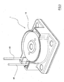
figure 3 shows a perspective view of the assembly offigure 1 . - With reference to the aforementioned figures, an electromagnetic actuator, applied to a
dosaging device 2 of a diaphragm carburettor, in accordance with the present invention, is globally indicated with 1. - The
diaphragm dosager 2 comprises adiaphragm 3 that keeps a chamber atconstant pressure 4, generally at atmospheric pressure, separate from adosaging chamber 5, only partially visible, communicating both with afuel inlet line 23 intercepted by aneedle valve 22 controlled by thediaphragm 3 itself, and with anozzle 24 for injecting fuel into the fuel inlet duct equipped with a Venturitube 25 and with a pair ofbutterfly valves 26. - The
chamber 5 communicates with the inlet duct also through thelow speed nozzle 240. - The needle valve is controlled by the
diaphragm 3 through alever 20 that acts in contrast to aspring 21, as known in the art and therefore not described in detail. - The
diaphragm dosager 2 is actuated by the pressure difference between the chamber atconstant pressure 4 and thedosaging chamber 5. - In particular and as known, when there are depressions in the
dosaging chamber 5, the atmospheric pressure present in theother chamber 4 exerts a sufficient force against thediaphragm 3 to deform it towards the inside of thedosaging chamber 5, consequently pushing thelever 20 that opens the needle valve. When the pressure inside thedosaging chamber 5 goes back to a value substantially equal to that present in theother chamber 4, i.e. atmospheric pressure, thediaphragm 3 goes back into the relaxed and undeformed position, thespring 21 takes thelever 20 back into the initial position, taking the valve back into the closed position. - In accordance with the present invention, the
diaphragm 3 is further controlled through theelectromagnetic actuator 1. - The
actuator 1 is made up of amobile coil 6 arranged entirely in the chamber atconstant pressure 4 and directly fixed to thediaphragm 3, and a fixed magnetic field generator, in the example apermanent magnet ring 7 associated withfield guides 11, which shall be discussed more later on. The passing of current through thecoil 6 generates an actuation force applied to thedosager 2 of the carburettor so as to influence the dosage of fuel to the motor. - The inversion of the direction of the flow of current generates a force in the opposite direction on the
diaphragm 3, and theactuator 1 is thus able to generate a force in both directions on thediaphragm 3, by simply inverting the polarity of thecoil 6. - In particular, the
coil 6 is wound on asupport 9 made from light plastic and shaped like a cup with the base fixed, through arivet 10, centrally to thediaphragm 3 itself, on the side of the chamber atconstant pressure 4. - The
coil 6 is positioned with its central axis perpendicular to the surface of thediaphragm 3 and centrally with respect to thedosaging chamber 5. - In the example, the head of the rivet 10 projects into the
dosaging chamber 5 so as to act as a connection head to the end of thelever 20 in contact with thediaphragm 3. - The electrical connections with the
coil 6 can be made in accordance with the known art. - In particular and in order to ensure high flexibility of use, good strength also in the presence of high vibrations as well as low production costs, such connections can be made through the use of a plurality of thin strands to form the winding, at each of the two ends forming a plait. These plaits are thus used to project from the space present between the
coil 6, fixed to thediaphragm 3 and free to move, and the fixed parts of the carburettor to connect with thefixed cables 40 from which the electricity arrives. - Alternatively, in order to ensure the flexible connections to the
coil 6, it is foreseen to use a flexible circuit element 30 (Fig. 2 ). - Such a
circuit 30 is formed through a printed copper circuit on a flexible base material like, for example, Mylar or Kapton. Thecircuit 30 is cut so as to form thin andflexible arms 31 containing the circuit tracks that extend through the space of themobile coil 6. Thanks to thisflexible circuit 30 it is possible to place it between thediaphragm 3 and thecoil 6 and join it to them so as to obtain a reduction in costs. - In order to have a robust and efficient actuator it is necessary to generate a strong magnetic field. To generate this field it is thus necessary to have a relatively large magnetic mass. The
permanent magnet 7, according to the present invention, is mounted on the fixed portion of the carburettor and not on the diaphragm as occurs in the prior art. - In particular, the
magnet 7, in the example, has an annular configuration, however it is possible to use any other configuration like for example disc-shaped. - The
field guides 11, made from iron, guide the magnetic circuit and allow thecoil 6 to be housed leaving extremely small spaces from themagnet 7. Thanks to the possibility of making a magnetic circuit with such small spaces, the density of the magnetic flow and therefore the efficiency of the actuator can be enormously increased, so as to be able to function even with little energy. - The
magnet 7 and theguides 11 are housed inside acylindrical casing 13 made from plastic material. - In particular, the
diaphragm 3 is fixed onto the base of thecasing 13, with the chamber atconstant pressure 4 formed inside it. Such achamber 4 has a bell-shaped configuration with anannular shoulder 4a supporting themagnet 7 arranged between two annular elements forming thefield guides 11. Centrally, thechamber 4 has a hole through which a further element passes forming thefield guides 11 that is placed partially inside thesupport 9 without touching it however. - In practice, the
magnet 7 and theguides 11 are neither directly nor indirectly in contact with thediaphragm 3. - The
casing 13 is easy to make and adapt to any type of carburettor. - As can be appreciated from what has been described, the diaphragm carburettor with electromagnetic actuator according to the present invention allows the requirements mentioned in the introductory part of the present description to be met.
- The described invention has numerous and important advantages.
- The described actuator is able to optimally correct the position of pressure equilibrium of the diaphragm of the dosager, using a variable amount of force that can be controlled electronically. Moreover, the actuator of the invention can also be applied to a low-cost carburettor, without impairing the behaviour of the entire system, as well as being able to operate in an environment with high vibrations, thanks to its compactness.
- The actuator of the invention is also structured in such as way as to allow a large displacement of the diaphragm and therefore to support a manual pump that does, indeed, cause said effect.
- The actuator consumes a small amount of electricity and can therefore be applied to products that generate a small available current, with great versatility of use.
- The actuator, thanks to its compactness and its design characteristics, can easily be adapted to multiple applications with small modifications to the pre-existing system, or else to the system to which it must be applied.
- In the invention, the portion of actuator that is attached to the diaphragm dosager is light. This characteristic, on the one hand, prevents the force of gravity that acts upon the actuator from being able to alter its behaviour in the different positions in which the motor is operated. On the other hand, the light weight does not change the behaviour of the actuator when there are large vibrations and allows high actuation speed to be reached even at low powers.
- The described actuator is highly versatile: indeed, it has been seen that it is able to produce a force in both directions and the direction of the force can easily be selected in a single direction or two-directional. Moreover, the actuation force of the actuator is easy to control in a simple and functional manner.
- The described actuator is also electrically efficient in the sense that the actuation force is generated with low energy consumption.
- It also has excellent electrical insulation, advantageous considering the fact that it is an electrical device that is in contact with flammable substances, like the fuel.
- The electrical circuits of the actuator are designed according to safety standards, known in the field of petrochemistry. This is obtained precisely because the energy contained in the reactive components is less than that required to inflame the flammable substances used. Added to this is the fact that low energy means low consumption, and therefore high efficiency. Finally, the actuator has high strength, so as to reduce maintenance costs.
- Of course, a man skilled in the art can make numerous modifications and variations to the carburettor described above, in order to satisfy contingent and specific requirements, all of which are also covered by the scope of protection of the invention, as defined by the following claims.
Claims (10)
- Diaphragm carburettor comprising a diaphragm dosager (2) provided with a diaphragm (3) arranged so as to keep a first chamber at constant pressure (4) separate from a second chamber (5) communicating both with a fuel inlet line intercepted by a valve controlled by the diaphragm (3) itself, and with an outlet line for injecting fuel, said valve being operatively connected with said diaphragm (3), the aforementioned carburettor foreseeing an electromagnetic actuator (1) associated with said diaphragm (3) to control the opening and closing of said valve, characterised in that said actuator (1) comprises at least one mobile coil (6) arranged entirely in said first chamber (4) and directly fixed to said diaphragm (3), and a fixed magnetic field generator (7) suitable for guiding said coil (6), said actuator (1) controlling said diaphragm (3) and therefore said valve when electrical current passes through the coil (6).
- Carburettor according to claim 1, in which said coil (6) is wound on an insulating support (9) fixed to the diaphragm (3) and free to slide with the wire of the coil with current passing through it wound on it.
- Carburettor according to claim 2, in which said support (9) has a cup-shaped configuration with the base (9a) fixed centrally to the diaphragm (3), the side wall being at least partially wound by said coil.
- Carburettor according to claim 3, in which said support (9) is made from plastic material and is fixed to the diaphragm (3) through fastening means (10) that project for a portion in said second chamber (5), said portion that projects being suitable for connecting with an actuation lever (20) of said valve.
- Carburettor according to claim 1, in which said magnetic field generator consists of a permanent magnet (7) with associated field guides (11), said magnet (7) being arranged outside of said first chamber (4).
- Carburettor according to claim 5, in which said magnet (7) has an annular configuration.
- Carburettor according to claim 6, in which said magnet (7) is arranged inside a cylindrical casing (13) on a base of which said diaphragm (3) is fixed, said first chamber (4) being formed inside said casing (13).
- Carburettor according to claim 7, in which said field guides (11) comprise a pair of opposite annular elements next to said magnet (7), which is arranged between them, and a further element having a cylindrical configuration and arranged partially inside said support (9) without touching it.
- Carburettor according to claim 1, in which a flexible printed circuit (30), suitable for maintaining the electrical supply of said mobile coil (6) with a current generator, is arranged between said coil (6) and said diaphragm (3);
- Carburettor according to claim 1, in which, through inversion of the direction of the flow of current, it is possible to invert the direction of the force acting upon the aforementioned diaphragm (3).
Applications Claiming Priority (2)
| Application Number | Priority Date | Filing Date | Title |
|---|---|---|---|
| US85200606P | 2006-10-17 | 2006-10-17 | |
| PCT/EP2007/060123 WO2008046719A1 (en) | 2006-10-17 | 2007-09-24 | Diaphragm carburettor with electromagnetic actuator |
Publications (2)
| Publication Number | Publication Date |
|---|---|
| EP2074325A1 EP2074325A1 (en) | 2009-07-01 |
| EP2074325B1 true EP2074325B1 (en) | 2010-01-06 |
Family
ID=38871551
Family Applications (1)
| Application Number | Title | Priority Date | Filing Date |
|---|---|---|---|
| EP07820529A Not-in-force EP2074325B1 (en) | 2006-10-17 | 2007-09-24 | Diaphragm carburettor with electromagnetic actuator |
Country Status (5)
| Country | Link |
|---|---|
| US (1) | US7770559B2 (en) |
| EP (1) | EP2074325B1 (en) |
| AT (1) | ATE454549T1 (en) |
| DE (1) | DE602007004243D1 (en) |
| WO (1) | WO2008046719A1 (en) |
Families Citing this family (8)
| Publication number | Priority date | Publication date | Assignee | Title |
|---|---|---|---|---|
| DE602007010656D1 (en) * | 2006-10-17 | 2010-12-30 | Selettra Srl | METHOD FOR DRIVING AN ELECTROMAGNETIC ACTUATOR IN A MEMBRANE CARBURETOR FOR CONTROLLING THE AIR-FUEL RATIO |
| CN104641097B (en) * | 2012-07-25 | 2018-02-13 | 沃尔布罗发动机使用有限责任公司 | Layered membranes |
| US9746176B2 (en) | 2014-06-04 | 2017-08-29 | Lochinvar, Llc | Modulating burner with venturi damper |
| DE112015005060T5 (en) * | 2014-11-06 | 2017-07-20 | Walbro Llc | pulse pump |
| DE102014226885B4 (en) * | 2014-12-22 | 2018-01-18 | Continental Automotive Gmbh | Valve |
| US10054082B2 (en) | 2015-10-20 | 2018-08-21 | Walbro Llc | Carburetor with fuel metering diaphragm |
| DE102016226106A1 (en) * | 2016-12-22 | 2018-06-28 | Continental Automotive Gmbh | Valve |
| DE102016226075A1 (en) * | 2016-12-22 | 2018-06-28 | Continental Automotive Gmbh | Valve |
Family Cites Families (9)
| Publication number | Priority date | Publication date | Assignee | Title |
|---|---|---|---|---|
| US3651283A (en) * | 1968-12-18 | 1972-03-21 | Audio Arts Inc | Loudspeaker having elongated rectangular moving coil |
| JP2563173B2 (en) * | 1987-05-06 | 1996-12-11 | 株式会社 ウオルブロ−フア−イ−スト | Overspeed prevention device for internal combustion engine |
| JPH07116989B2 (en) * | 1988-11-26 | 1995-12-18 | 株式会社ウオルブローファーイースト | Starting fuel supply system for engine equipped with diaphragm type carburetor |
| DE4328989B4 (en) * | 1993-08-28 | 2007-05-16 | Stihl Maschf Andreas | Diaphragm carburetor with a solenoid for opening the intake valve |
| DE19913073C2 (en) * | 1999-03-23 | 2001-04-05 | Wacker Werke Kg | Fuel metering device |
| US6672570B2 (en) * | 2000-11-17 | 2004-01-06 | Walbro Japan, Inc. | Variable venturi carburetor |
| JP4081245B2 (en) * | 2001-04-13 | 2008-04-23 | 株式会社共立 | FUEL INJECTION DEVICE AND MIXTURE GENERATION DEVICE INCLUDING THE SAME |
| US6585235B2 (en) * | 2001-10-11 | 2003-07-01 | Walbro Corporation | Fuel regulating mechanism and method for a rotary throttle valve type carburetor |
| US7264230B2 (en) * | 2005-01-11 | 2007-09-04 | Walbro Engine Management, L.L.C. | Carburetor and solenoid assemblies and methods of assembling the same |
-
2007
- 2007-09-24 DE DE602007004243T patent/DE602007004243D1/en active Active
- 2007-09-24 EP EP07820529A patent/EP2074325B1/en not_active Not-in-force
- 2007-09-24 WO PCT/EP2007/060123 patent/WO2008046719A1/en not_active Ceased
- 2007-09-24 AT AT07820529T patent/ATE454549T1/en not_active IP Right Cessation
- 2007-10-17 US US11/873,742 patent/US7770559B2/en not_active Expired - Fee Related
Also Published As
| Publication number | Publication date |
|---|---|
| DE602007004243D1 (en) | 2010-02-25 |
| WO2008046719A1 (en) | 2008-04-24 |
| ATE454549T1 (en) | 2010-01-15 |
| US7770559B2 (en) | 2010-08-10 |
| EP2074325A1 (en) | 2009-07-01 |
| US20080203344A1 (en) | 2008-08-28 |
Similar Documents
| Publication | Publication Date | Title |
|---|---|---|
| US7770559B2 (en) | Diaphragm carburettor with electromagnetic actuator | |
| KR890013400A (en) | Electronic control valve mechanism and bistable electronic control transducer | |
| US6161783A (en) | Gaseous fuel injector | |
| JPS5838626B2 (en) | How to proceed with the construction of Congo | |
| US4465044A (en) | Electrically controlled fuel injection pump for an internal combustion engine | |
| EP1170486A3 (en) | Electronic throttle control mechanism with integrated modular construction | |
| EP2971900B1 (en) | Apparatus for controlling the lift of a valve member | |
| US2457739A (en) | Oil dilution and primer system for internal-combustion engines | |
| KR20010102033A (en) | Fuel Injection Valve | |
| US3174433A (en) | Electric pump | |
| EP1336747A2 (en) | Electrical injector for gaseous fuel | |
| KR19990082464A (en) | Gas valve | |
| US2803195A (en) | Fuel pump | |
| US3273505A (en) | Electrically operated fuel pump | |
| PL191054B1 (en) | Metering valve and fuel supply system equipped therewith | |
| US4573932A (en) | Electrical fluid pumping device including first and second pumping portions | |
| US6860254B2 (en) | Carburetor | |
| JPH11210591A (en) | Fuel injection device with center fuel line and pulsation closing mechanism | |
| JP4349976B2 (en) | Engine intake control device | |
| US11473531B2 (en) | Carburetor | |
| EP3426957B1 (en) | Injector for a system for feeding gas fuel to an internal combustion engine | |
| KR101842595B1 (en) | Cover Assembly of fuel tank for vehicle | |
| JP3119870U (en) | Gas fuel supply device | |
| CN114526352B (en) | Gas equipment and valve body assembly applied to same | |
| WO2025197211A1 (en) | Gas fuel supply device and engine generator |
Legal Events
| Date | Code | Title | Description |
|---|---|---|---|
| PUAI | Public reference made under article 153(3) epc to a published international application that has entered the european phase |
Free format text: ORIGINAL CODE: 0009012 |
|
| 17P | Request for examination filed |
Effective date: 20090313 |
|
| AK | Designated contracting states |
Kind code of ref document: A1 Designated state(s): AT BE BG CH CY CZ DE DK EE ES FI FR GB GR HU IE IS IT LI LT LU LV MC MT NL PL PT RO SE SI SK TR |
|
| AX | Request for extension of the european patent |
Extension state: AL BA HR MK RS |
|
| GRAP | Despatch of communication of intention to grant a patent |
Free format text: ORIGINAL CODE: EPIDOSNIGR1 |
|
| DAX | Request for extension of the european patent (deleted) | ||
| GRAS | Grant fee paid |
Free format text: ORIGINAL CODE: EPIDOSNIGR3 |
|
| GRAA | (expected) grant |
Free format text: ORIGINAL CODE: 0009210 |
|
| AK | Designated contracting states |
Kind code of ref document: B1 Designated state(s): AT BE BG CH CY CZ DE DK EE ES FI FR GB GR HU IE IS IT LI LT LU LV MC MT NL PL PT RO SE SI SK TR |
|
| REG | Reference to a national code |
Ref country code: GB Ref legal event code: FG4D |
|
| REG | Reference to a national code |
Ref country code: CH Ref legal event code: EP |
|
| REG | Reference to a national code |
Ref country code: IE Ref legal event code: FG4D |
|
| REF | Corresponds to: |
Ref document number: 602007004243 Country of ref document: DE Date of ref document: 20100225 Kind code of ref document: P |
|
| REG | Reference to a national code |
Ref country code: NL Ref legal event code: VDEP Effective date: 20100106 |
|
| PG25 | Lapsed in a contracting state [announced via postgrant information from national office to epo] |
Ref country code: SI Free format text: LAPSE BECAUSE OF FAILURE TO SUBMIT A TRANSLATION OF THE DESCRIPTION OR TO PAY THE FEE WITHIN THE PRESCRIBED TIME-LIMIT Effective date: 20100106 |
|
| LTIE | Lt: invalidation of european patent or patent extension |
Effective date: 20100106 |
|
| PG25 | Lapsed in a contracting state [announced via postgrant information from national office to epo] |
Ref country code: AT Free format text: LAPSE BECAUSE OF FAILURE TO SUBMIT A TRANSLATION OF THE DESCRIPTION OR TO PAY THE FEE WITHIN THE PRESCRIBED TIME-LIMIT Effective date: 20100106 |
|
| PG25 | Lapsed in a contracting state [announced via postgrant information from national office to epo] |
Ref country code: LT Free format text: LAPSE BECAUSE OF FAILURE TO SUBMIT A TRANSLATION OF THE DESCRIPTION OR TO PAY THE FEE WITHIN THE PRESCRIBED TIME-LIMIT Effective date: 20100106 Ref country code: NL Free format text: LAPSE BECAUSE OF FAILURE TO SUBMIT A TRANSLATION OF THE DESCRIPTION OR TO PAY THE FEE WITHIN THE PRESCRIBED TIME-LIMIT Effective date: 20100106 Ref country code: IS Free format text: LAPSE BECAUSE OF FAILURE TO SUBMIT A TRANSLATION OF THE DESCRIPTION OR TO PAY THE FEE WITHIN THE PRESCRIBED TIME-LIMIT Effective date: 20100506 Ref country code: ES Free format text: LAPSE BECAUSE OF FAILURE TO SUBMIT A TRANSLATION OF THE DESCRIPTION OR TO PAY THE FEE WITHIN THE PRESCRIBED TIME-LIMIT Effective date: 20100417 Ref country code: PT Free format text: LAPSE BECAUSE OF FAILURE TO SUBMIT A TRANSLATION OF THE DESCRIPTION OR TO PAY THE FEE WITHIN THE PRESCRIBED TIME-LIMIT Effective date: 20100506 |
|
| PG25 | Lapsed in a contracting state [announced via postgrant information from national office to epo] |
Ref country code: LV Free format text: LAPSE BECAUSE OF FAILURE TO SUBMIT A TRANSLATION OF THE DESCRIPTION OR TO PAY THE FEE WITHIN THE PRESCRIBED TIME-LIMIT Effective date: 20100106 Ref country code: FI Free format text: LAPSE BECAUSE OF FAILURE TO SUBMIT A TRANSLATION OF THE DESCRIPTION OR TO PAY THE FEE WITHIN THE PRESCRIBED TIME-LIMIT Effective date: 20100106 Ref country code: PL Free format text: LAPSE BECAUSE OF FAILURE TO SUBMIT A TRANSLATION OF THE DESCRIPTION OR TO PAY THE FEE WITHIN THE PRESCRIBED TIME-LIMIT Effective date: 20100106 |
|
| PG25 | Lapsed in a contracting state [announced via postgrant information from national office to epo] |
Ref country code: SE Free format text: LAPSE BECAUSE OF FAILURE TO SUBMIT A TRANSLATION OF THE DESCRIPTION OR TO PAY THE FEE WITHIN THE PRESCRIBED TIME-LIMIT Effective date: 20100106 Ref country code: GR Free format text: LAPSE BECAUSE OF FAILURE TO SUBMIT A TRANSLATION OF THE DESCRIPTION OR TO PAY THE FEE WITHIN THE PRESCRIBED TIME-LIMIT Effective date: 20100407 Ref country code: EE Free format text: LAPSE BECAUSE OF FAILURE TO SUBMIT A TRANSLATION OF THE DESCRIPTION OR TO PAY THE FEE WITHIN THE PRESCRIBED TIME-LIMIT Effective date: 20100106 Ref country code: CY Free format text: LAPSE BECAUSE OF FAILURE TO SUBMIT A TRANSLATION OF THE DESCRIPTION OR TO PAY THE FEE WITHIN THE PRESCRIBED TIME-LIMIT Effective date: 20100106 Ref country code: BE Free format text: LAPSE BECAUSE OF FAILURE TO SUBMIT A TRANSLATION OF THE DESCRIPTION OR TO PAY THE FEE WITHIN THE PRESCRIBED TIME-LIMIT Effective date: 20100106 Ref country code: RO Free format text: LAPSE BECAUSE OF FAILURE TO SUBMIT A TRANSLATION OF THE DESCRIPTION OR TO PAY THE FEE WITHIN THE PRESCRIBED TIME-LIMIT Effective date: 20100106 |
|
| PLBE | No opposition filed within time limit |
Free format text: ORIGINAL CODE: 0009261 |
|
| STAA | Information on the status of an ep patent application or granted ep patent |
Free format text: STATUS: NO OPPOSITION FILED WITHIN TIME LIMIT |
|
| PG25 | Lapsed in a contracting state [announced via postgrant information from national office to epo] |
Ref country code: SK Free format text: LAPSE BECAUSE OF FAILURE TO SUBMIT A TRANSLATION OF THE DESCRIPTION OR TO PAY THE FEE WITHIN THE PRESCRIBED TIME-LIMIT Effective date: 20100106 Ref country code: CZ Free format text: LAPSE BECAUSE OF FAILURE TO SUBMIT A TRANSLATION OF THE DESCRIPTION OR TO PAY THE FEE WITHIN THE PRESCRIBED TIME-LIMIT Effective date: 20100106 Ref country code: BG Free format text: LAPSE BECAUSE OF FAILURE TO SUBMIT A TRANSLATION OF THE DESCRIPTION OR TO PAY THE FEE WITHIN THE PRESCRIBED TIME-LIMIT Effective date: 20100406 |
|
| 26N | No opposition filed |
Effective date: 20101007 |
|
| PG25 | Lapsed in a contracting state [announced via postgrant information from national office to epo] |
Ref country code: DK Free format text: LAPSE BECAUSE OF FAILURE TO SUBMIT A TRANSLATION OF THE DESCRIPTION OR TO PAY THE FEE WITHIN THE PRESCRIBED TIME-LIMIT Effective date: 20100106 |
|
| PG25 | Lapsed in a contracting state [announced via postgrant information from national office to epo] |
Ref country code: MC Free format text: LAPSE BECAUSE OF NON-PAYMENT OF DUE FEES Effective date: 20100930 |
|
| REG | Reference to a national code |
Ref country code: FR Ref legal event code: ST Effective date: 20110531 |
|
| PG25 | Lapsed in a contracting state [announced via postgrant information from national office to epo] |
Ref country code: FR Free format text: LAPSE BECAUSE OF NON-PAYMENT OF DUE FEES Effective date: 20100930 Ref country code: IE Free format text: LAPSE BECAUSE OF NON-PAYMENT OF DUE FEES Effective date: 20100924 |
|
| PG25 | Lapsed in a contracting state [announced via postgrant information from national office to epo] |
Ref country code: MT Free format text: LAPSE BECAUSE OF FAILURE TO SUBMIT A TRANSLATION OF THE DESCRIPTION OR TO PAY THE FEE WITHIN THE PRESCRIBED TIME-LIMIT Effective date: 20100106 |
|
| REG | Reference to a national code |
Ref country code: CH Ref legal event code: PL |
|
| GBPC | Gb: european patent ceased through non-payment of renewal fee |
Effective date: 20110924 |
|
| PG25 | Lapsed in a contracting state [announced via postgrant information from national office to epo] |
Ref country code: CH Free format text: LAPSE BECAUSE OF NON-PAYMENT OF DUE FEES Effective date: 20110930 Ref country code: LI Free format text: LAPSE BECAUSE OF NON-PAYMENT OF DUE FEES Effective date: 20110930 |
|
| PG25 | Lapsed in a contracting state [announced via postgrant information from national office to epo] |
Ref country code: GB Free format text: LAPSE BECAUSE OF NON-PAYMENT OF DUE FEES Effective date: 20110924 |
|
| PG25 | Lapsed in a contracting state [announced via postgrant information from national office to epo] |
Ref country code: HU Free format text: LAPSE BECAUSE OF FAILURE TO SUBMIT A TRANSLATION OF THE DESCRIPTION OR TO PAY THE FEE WITHIN THE PRESCRIBED TIME-LIMIT Effective date: 20100707 Ref country code: LU Free format text: LAPSE BECAUSE OF NON-PAYMENT OF DUE FEES Effective date: 20100924 |
|
| PG25 | Lapsed in a contracting state [announced via postgrant information from national office to epo] |
Ref country code: TR Free format text: LAPSE BECAUSE OF FAILURE TO SUBMIT A TRANSLATION OF THE DESCRIPTION OR TO PAY THE FEE WITHIN THE PRESCRIBED TIME-LIMIT Effective date: 20100106 |
|
| PGFP | Annual fee paid to national office [announced via postgrant information from national office to epo] |
Ref country code: DE Payment date: 20130927 Year of fee payment: 7 |
|
| PGFP | Annual fee paid to national office [announced via postgrant information from national office to epo] |
Ref country code: IT Payment date: 20130828 Year of fee payment: 7 |
|
| REG | Reference to a national code |
Ref country code: DE Ref legal event code: R119 Ref document number: 602007004243 Country of ref document: DE |
|
| REG | Reference to a national code |
Ref country code: DE Ref legal event code: R119 Ref document number: 602007004243 Country of ref document: DE Effective date: 20150401 |
|
| PG25 | Lapsed in a contracting state [announced via postgrant information from national office to epo] |
Ref country code: DE Free format text: LAPSE BECAUSE OF NON-PAYMENT OF DUE FEES Effective date: 20150401 |
|
| PG25 | Lapsed in a contracting state [announced via postgrant information from national office to epo] |
Ref country code: IT Free format text: LAPSE BECAUSE OF NON-PAYMENT OF DUE FEES Effective date: 20140924 |