EP2073914B1 - Calcium looping process for high purity hydrogen production - Google Patents
Calcium looping process for high purity hydrogen production Download PDFInfo
- Publication number
- EP2073914B1 EP2073914B1 EP07853625.7A EP07853625A EP2073914B1 EP 2073914 B1 EP2073914 B1 EP 2073914B1 EP 07853625 A EP07853625 A EP 07853625A EP 2073914 B1 EP2073914 B1 EP 2073914B1
- Authority
- EP
- European Patent Office
- Prior art keywords
- cao
- steam
- hydrogen
- gas
- sorbent
- Prior art date
- Legal status (The legal status is an assumption and is not a legal conclusion. Google has not performed a legal analysis and makes no representation as to the accuracy of the status listed.)
- Active
Links
Images












Classifications
-
- C—CHEMISTRY; METALLURGY
- C01—INORGANIC CHEMISTRY
- C01B—NON-METALLIC ELEMENTS; COMPOUNDS THEREOF; METALLOIDS OR COMPOUNDS THEREOF NOT COVERED BY SUBCLASS C01C
- C01B3/00—Hydrogen; Gaseous mixtures containing hydrogen; Separation of hydrogen from mixtures containing it; Purification of hydrogen; Reversible storage of hydrogen
- C01B3/02—Production of hydrogen; Production of gaseous mixtures containing hydrogen
- C01B3/32—Production of hydrogen; Production of gaseous mixtures containing hydrogen by reaction of gaseous or liquid organic compounds with gasifying agents, e.g. water, carbon dioxide or air
- C01B3/34—Production of hydrogen; Production of gaseous mixtures containing hydrogen by reaction of gaseous or liquid organic compounds with gasifying agents, e.g. water, carbon dioxide or air by reaction of hydrocarbons with gasifying agents
- C01B3/38—Production of hydrogen; Production of gaseous mixtures containing hydrogen by reaction of gaseous or liquid organic compounds with gasifying agents, e.g. water, carbon dioxide or air by reaction of hydrocarbons with gasifying agents using catalysts
-
- C—CHEMISTRY; METALLURGY
- C01—INORGANIC CHEMISTRY
- C01B—NON-METALLIC ELEMENTS; COMPOUNDS THEREOF; METALLOIDS OR COMPOUNDS THEREOF NOT COVERED BY SUBCLASS C01C
- C01B3/00—Hydrogen; Gaseous mixtures containing hydrogen; Separation of hydrogen from mixtures containing it; Purification of hydrogen; Reversible storage of hydrogen
- C01B3/02—Production of hydrogen; Production of gaseous mixtures containing hydrogen
- C01B3/32—Production of hydrogen; Production of gaseous mixtures containing hydrogen by reaction of gaseous or liquid organic compounds with gasifying agents, e.g. water, carbon dioxide or air
- C01B3/34—Production of hydrogen; Production of gaseous mixtures containing hydrogen by reaction of gaseous or liquid organic compounds with gasifying agents, e.g. water, carbon dioxide or air by reaction of hydrocarbons with gasifying agents
- C01B3/38—Production of hydrogen; Production of gaseous mixtures containing hydrogen by reaction of gaseous or liquid organic compounds with gasifying agents, e.g. water, carbon dioxide or air by reaction of hydrocarbons with gasifying agents using catalysts
- C01B3/386—Catalytic partial combustion
-
- C—CHEMISTRY; METALLURGY
- C01—INORGANIC CHEMISTRY
- C01B—NON-METALLIC ELEMENTS; COMPOUNDS THEREOF; METALLOIDS OR COMPOUNDS THEREOF NOT COVERED BY SUBCLASS C01C
- C01B3/00—Hydrogen; Gaseous mixtures containing hydrogen; Separation of hydrogen from mixtures containing it; Purification of hydrogen; Reversible storage of hydrogen
- C01B3/50—Separation of hydrogen or hydrogen-containing gases from gaseous mixtures, e.g. purification
- C01B3/56—Separation of hydrogen or hydrogen-containing gases from gaseous mixtures, e.g. purification by contacting with solids; Regeneration of used solids
-
- C—CHEMISTRY; METALLURGY
- C10—PETROLEUM, GAS OR COKE INDUSTRIES; TECHNICAL GASES CONTAINING CARBON MONOXIDE; FUELS; LUBRICANTS; PEAT
- C10K—PURIFYING OR MODIFYING THE CHEMICAL COMPOSITION OF COMBUSTIBLE GASES CONTAINING CARBON MONOXIDE
- C10K3/00—Modifying the chemical composition of combustible gases containing carbon monoxide to produce an improved fuel, e.g. one of different calorific value, which may be free from carbon monoxide
- C10K3/02—Modifying the chemical composition of combustible gases containing carbon monoxide to produce an improved fuel, e.g. one of different calorific value, which may be free from carbon monoxide by catalytic treatment
- C10K3/04—Modifying the chemical composition of combustible gases containing carbon monoxide to produce an improved fuel, e.g. one of different calorific value, which may be free from carbon monoxide by catalytic treatment reducing the carbon monoxide content, e.g. water-gas shift [WGS]
-
- C—CHEMISTRY; METALLURGY
- C01—INORGANIC CHEMISTRY
- C01B—NON-METALLIC ELEMENTS; COMPOUNDS THEREOF; METALLOIDS OR COMPOUNDS THEREOF NOT COVERED BY SUBCLASS C01C
- C01B2203/00—Integrated processes for the production of hydrogen or synthesis gas
- C01B2203/02—Processes for making hydrogen or synthesis gas
- C01B2203/0205—Processes for making hydrogen or synthesis gas containing a reforming step
- C01B2203/0227—Processes for making hydrogen or synthesis gas containing a reforming step containing a catalytic reforming step
- C01B2203/0233—Processes for making hydrogen or synthesis gas containing a reforming step containing a catalytic reforming step the reforming step being a steam reforming step
-
- C—CHEMISTRY; METALLURGY
- C01—INORGANIC CHEMISTRY
- C01B—NON-METALLIC ELEMENTS; COMPOUNDS THEREOF; METALLOIDS OR COMPOUNDS THEREOF NOT COVERED BY SUBCLASS C01C
- C01B2203/00—Integrated processes for the production of hydrogen or synthesis gas
- C01B2203/02—Processes for making hydrogen or synthesis gas
- C01B2203/0205—Processes for making hydrogen or synthesis gas containing a reforming step
- C01B2203/0227—Processes for making hydrogen or synthesis gas containing a reforming step containing a catalytic reforming step
- C01B2203/0238—Processes for making hydrogen or synthesis gas containing a reforming step containing a catalytic reforming step the reforming step being a carbon dioxide reforming step
-
- C—CHEMISTRY; METALLURGY
- C01—INORGANIC CHEMISTRY
- C01B—NON-METALLIC ELEMENTS; COMPOUNDS THEREOF; METALLOIDS OR COMPOUNDS THEREOF NOT COVERED BY SUBCLASS C01C
- C01B2203/00—Integrated processes for the production of hydrogen or synthesis gas
- C01B2203/02—Processes for making hydrogen or synthesis gas
- C01B2203/025—Processes for making hydrogen or synthesis gas containing a partial oxidation step
- C01B2203/0261—Processes for making hydrogen or synthesis gas containing a partial oxidation step containing a catalytic partial oxidation step [CPO]
-
- C—CHEMISTRY; METALLURGY
- C01—INORGANIC CHEMISTRY
- C01B—NON-METALLIC ELEMENTS; COMPOUNDS THEREOF; METALLOIDS OR COMPOUNDS THEREOF NOT COVERED BY SUBCLASS C01C
- C01B2203/00—Integrated processes for the production of hydrogen or synthesis gas
- C01B2203/02—Processes for making hydrogen or synthesis gas
- C01B2203/0283—Processes for making hydrogen or synthesis gas containing a CO-shift step, i.e. a water gas shift step
-
- C—CHEMISTRY; METALLURGY
- C01—INORGANIC CHEMISTRY
- C01B—NON-METALLIC ELEMENTS; COMPOUNDS THEREOF; METALLOIDS OR COMPOUNDS THEREOF NOT COVERED BY SUBCLASS C01C
- C01B2203/00—Integrated processes for the production of hydrogen or synthesis gas
- C01B2203/04—Integrated processes for the production of hydrogen or synthesis gas containing a purification step for the hydrogen or the synthesis gas
- C01B2203/042—Purification by adsorption on solids
- C01B2203/0425—In-situ adsorption process during hydrogen production
-
- C—CHEMISTRY; METALLURGY
- C01—INORGANIC CHEMISTRY
- C01B—NON-METALLIC ELEMENTS; COMPOUNDS THEREOF; METALLOIDS OR COMPOUNDS THEREOF NOT COVERED BY SUBCLASS C01C
- C01B2203/00—Integrated processes for the production of hydrogen or synthesis gas
- C01B2203/04—Integrated processes for the production of hydrogen or synthesis gas containing a purification step for the hydrogen or the synthesis gas
- C01B2203/042—Purification by adsorption on solids
- C01B2203/043—Regenerative adsorption process in two or more beds, one for adsorption, the other for regeneration
-
- C—CHEMISTRY; METALLURGY
- C01—INORGANIC CHEMISTRY
- C01B—NON-METALLIC ELEMENTS; COMPOUNDS THEREOF; METALLOIDS OR COMPOUNDS THEREOF NOT COVERED BY SUBCLASS C01C
- C01B2203/00—Integrated processes for the production of hydrogen or synthesis gas
- C01B2203/04—Integrated processes for the production of hydrogen or synthesis gas containing a purification step for the hydrogen or the synthesis gas
- C01B2203/0465—Composition of the impurity
-
- C—CHEMISTRY; METALLURGY
- C01—INORGANIC CHEMISTRY
- C01B—NON-METALLIC ELEMENTS; COMPOUNDS THEREOF; METALLOIDS OR COMPOUNDS THEREOF NOT COVERED BY SUBCLASS C01C
- C01B2203/00—Integrated processes for the production of hydrogen or synthesis gas
- C01B2203/04—Integrated processes for the production of hydrogen or synthesis gas containing a purification step for the hydrogen or the synthesis gas
- C01B2203/0465—Composition of the impurity
- C01B2203/0475—Composition of the impurity the impurity being carbon dioxide
-
- C—CHEMISTRY; METALLURGY
- C01—INORGANIC CHEMISTRY
- C01B—NON-METALLIC ELEMENTS; COMPOUNDS THEREOF; METALLOIDS OR COMPOUNDS THEREOF NOT COVERED BY SUBCLASS C01C
- C01B2203/00—Integrated processes for the production of hydrogen or synthesis gas
- C01B2203/04—Integrated processes for the production of hydrogen or synthesis gas containing a purification step for the hydrogen or the synthesis gas
- C01B2203/0465—Composition of the impurity
- C01B2203/0485—Composition of the impurity the impurity being a sulfur compound
-
- C—CHEMISTRY; METALLURGY
- C01—INORGANIC CHEMISTRY
- C01B—NON-METALLIC ELEMENTS; COMPOUNDS THEREOF; METALLOIDS OR COMPOUNDS THEREOF NOT COVERED BY SUBCLASS C01C
- C01B2203/00—Integrated processes for the production of hydrogen or synthesis gas
- C01B2203/10—Catalysts for performing the hydrogen forming reactions
- C01B2203/1041—Composition of the catalyst
-
- C—CHEMISTRY; METALLURGY
- C01—INORGANIC CHEMISTRY
- C01B—NON-METALLIC ELEMENTS; COMPOUNDS THEREOF; METALLOIDS OR COMPOUNDS THEREOF NOT COVERED BY SUBCLASS C01C
- C01B2203/00—Integrated processes for the production of hydrogen or synthesis gas
- C01B2203/80—Aspect of integrated processes for the production of hydrogen or synthesis gas not covered by groups C01B2203/02 - C01B2203/1695
- C01B2203/86—Carbon dioxide sequestration
-
- C—CHEMISTRY; METALLURGY
- C10—PETROLEUM, GAS OR COKE INDUSTRIES; TECHNICAL GASES CONTAINING CARBON MONOXIDE; FUELS; LUBRICANTS; PEAT
- C10J—PRODUCTION OF PRODUCER GAS, WATER-GAS, SYNTHESIS GAS FROM SOLID CARBONACEOUS MATERIAL, OR MIXTURES CONTAINING THESE GASES; CARBURETTING AIR OR OTHER GASES
- C10J2300/00—Details of gasification processes
- C10J2300/09—Details of the feed, e.g. feeding of spent catalyst, inert gas or halogens
- C10J2300/0913—Carbonaceous raw material
- C10J2300/093—Coal
-
- C—CHEMISTRY; METALLURGY
- C10—PETROLEUM, GAS OR COKE INDUSTRIES; TECHNICAL GASES CONTAINING CARBON MONOXIDE; FUELS; LUBRICANTS; PEAT
- C10J—PRODUCTION OF PRODUCER GAS, WATER-GAS, SYNTHESIS GAS FROM SOLID CARBONACEOUS MATERIAL, OR MIXTURES CONTAINING THESE GASES; CARBURETTING AIR OR OTHER GASES
- C10J2300/00—Details of gasification processes
- C10J2300/09—Details of the feed, e.g. feeding of spent catalyst, inert gas or halogens
- C10J2300/0983—Additives
- C10J2300/0996—Calcium-containing inorganic materials, e.g. lime
-
- C—CHEMISTRY; METALLURGY
- C10—PETROLEUM, GAS OR COKE INDUSTRIES; TECHNICAL GASES CONTAINING CARBON MONOXIDE; FUELS; LUBRICANTS; PEAT
- C10J—PRODUCTION OF PRODUCER GAS, WATER-GAS, SYNTHESIS GAS FROM SOLID CARBONACEOUS MATERIAL, OR MIXTURES CONTAINING THESE GASES; CARBURETTING AIR OR OTHER GASES
- C10J2300/00—Details of gasification processes
- C10J2300/16—Integration of gasification processes with another plant or parts within the plant
- C10J2300/164—Integration of gasification processes with another plant or parts within the plant with conversion of synthesis gas
- C10J2300/1656—Conversion of synthesis gas to chemicals
- C10J2300/1659—Conversion of synthesis gas to chemicals to liquid hydrocarbons
-
- Y—GENERAL TAGGING OF NEW TECHNOLOGICAL DEVELOPMENTS; GENERAL TAGGING OF CROSS-SECTIONAL TECHNOLOGIES SPANNING OVER SEVERAL SECTIONS OF THE IPC; TECHNICAL SUBJECTS COVERED BY FORMER USPC CROSS-REFERENCE ART COLLECTIONS [XRACs] AND DIGESTS
- Y02—TECHNOLOGIES OR APPLICATIONS FOR MITIGATION OR ADAPTATION AGAINST CLIMATE CHANGE
- Y02P—CLIMATE CHANGE MITIGATION TECHNOLOGIES IN THE PRODUCTION OR PROCESSING OF GOODS
- Y02P30/00—Technologies relating to oil refining and petrochemical industry
Definitions
- H Gupta et al discloses enhanced hydrogen production integrated with CO2 separation in a single-stage reactor (DOE annual technical progress report, (20050310), pages 1 - 30, url: http://www.osti.gov/energycitations/servlets/purl/838225-oekae3/native/838225.pdf ).
- J Abbasian et al discloses the effect of HCL on sulfidation of calcium oxide (Chemical Engineering Science, vol. 48, no. 15, pages 2689 - 2695 ).
- Gupta H et al discloses carbonation-calcination cycle using high reactivity calcium oxide for carbon dioxide separation from flue gas (Industrial & Engineering Chemistry Research, American Chemical Society, US, (20021107), vol. 41, no. 16, doi:10.1021/ie010867I, ISSN 0888-5885, pages 4035 -4042 ).
- the disclosed embodiments include a process for producing hydrogen, comprising the steps of: (a) gasifying a fuel into a raw synthesis gas comprising CO, hydrogen, steam and sulfur and halide contaminants in the form of H 2 S, COS and HX, where X is a halide; (b) injecting said raw synthesis gas, CaO and steam into a water gas shift reactor (WGSR), wherein said raw synthesis gas transforms into a shifted gas without a catalyst; allowing said shifted gas to react with said CaO in said WGSR so as to remove CO 2 , sulfur and halides in a solid-phase calcium-containing product comprising CaCO 3 , CaS and CaX 2 ; (c) separating the solid-phase calcium-containing product from an enriched gaseous hydrogen product; and (d) regenerating the CaO by calcining the solid-phase calcium-containing product at a condition selected from the group consisting of: in the presence of steam, in the presence of CO 2 , in the presence of synthesis gas, in the
- the fuel could be coal, biomass, oil sands, coke, tar, wax oil shales, or combinations of these materials.
- the steam injected is in the range of from about the stoichiometric requirement to about 3 times the stoichiometric requirement.
- the enriched hydrogen product has a purity of at least 60%. In one embodiment, the H 2 :CO ratio of the enriched hydrogen product is in the range of from about 0.5:1 to about 1000:1. In some embodiments the enriched hydrogen product has a purity in the range of from about 70% to about 99.99%, at temperature in the range of from about 400 - 1000 C, and a pressure in the range of from about 1 to about 100 atmospheres.
- the WGSR may be of a type selected from the group consisting of: fixed bed reactors, fluidized bed reactors, entrained flow reactors, moving bed reactors rotary kilns, or combinations thereof.
- the calcinations step may be performed in a calcinations reactor of a type selected from the group consisting of: fixed bed reactors, fluidized bed reactors, entrained flow reactors, moving bed reactors rotary kilns, or combinations thereof.
- the WGSR does not have a catalyst disposed therein. As such the WGSR operates at a temperature in the range of from about 550 - 750 C, in the pressure range of from about 1 to about 60 atm, it is preferred that the WGSR reactor operate in a temperature range of from about 600 - 700C and at a pressure in the range of from about 20 to about 30 atm.
- the enriched hydrogen product is 99% pure when 3 times the stoichiometric steam requirement is used. At the stoichiometric steam requirement the process produces an enriched hydrogen product that is 90% pure.
- the enriched hydrogen product has a H2/Co ration of at least 2.5 and a maximum sulfur (H 2 S/COS) concentration of less than 10 ppm using only the stoichiometric requirement of steam.
- a catalyst may be used in the WGSR.
- a suitable high temperature shift catalyst which may include: Fe, Cu, Co, Mo, W, Cs, Pt, Ph, Pd, and other precious metal catalysts or their oxides or sulfides or combinations thereof.
- Suitable supports for use with the foregoing high temperature shift catalysts include: Cr 2 O 3 , ZnO, MgO, ceria, alumina, silica, zirconia and combinations thereof.
- a WGSR reactor with a catalyst operates in the temperature range of from about 550 - 750 C and at a pressure in the range of from about 1 to about 100 atm. It is preferred that the WGSR reactor operate in the temperature range of from about 600 - 700 C and at a pressure of from about 20 to about 30 amt.
- the enriched hydrogen product may achieve 99.99% purity when 3x the stoichiometric requirement of steam is used in the WGSR.
- the enriched hydrogen product may achieve 98% purity when the stoichiometric requirement of steam is used.
- Some embodiments may attain a purity of at least 80% with a maximum sulfur (H 2 S/COS) concentration of less than 10 ppm when 3X the stoichiometric requirement of steam is used and at least 70% purity with a maximum sulfur concentration of less than 1 ppm when the stoichiometric requirement of steam is used.
- H 2 S/COS maximum sulfur
- the process may also comprise the step of (e) recycling at least a portion of a product stream from a Fischer-Tropsch reactor, fed by the WGSR, so as to introduce a chemical species selected from the group consisting of: methane, C1 - C4 hydrocarbons, CO, hydrogen and combinations thereof back into the WGSR.
- the CaO may have a surface area of at least 12.0 m 2 /g and a pore volume of at least 0.015 cm 3 /g, said CaO having a sorption capacity of at least about 70 grams of CO 2 per kilogram of CaO.
- the CaO may be provided in any usable form including, but not limited to, pellets, granules, fines, monoliths and combinations thereof.
- the CaO may be obtained by processing chicken eggshells.
- the regeneration of CaO step may be performed any functional process, it is preferred that it is conducted by a process selected from the group consisting of: (a) calcining in the presence of steam and/or CO 2 and/or H 2 with O 2 , and/or synthesis gas with O 2 and/or under partial vacuum or combinations thereof; (b) a process in which the heat is added to the calciner using steam and a combination of calciner fuel and oxidant; (c) a process in which the calciner fuel is H 2 or natural gas or synthesis gas or coal or combinations thereof; (d) a process in which the oxidant is air or oxygen or combinations thereof; (e) a process in which heat is provided to the calciner directly or indirectly; (f) calciner reactor temperatures ranging from about 700 - 1100 C; and (a process for adjusting the calciner temperature by modifying the CaO to CaCO 3 ratio in the calciner.
- the gas phase product from the calciner may comprise pure CO 2 and could also contain trace amounts of H 2 S
- the disclosure also includes a process for producing hydrogen, comprising the steps of: (a) reforming a gaseous hydrocarbon fuel in the presence of CaO and steam to remove CO 2 , sulfur and halide contaminants in the form of H 2 S, COS and HX, where X is a halide, in a solid-phase calcium-containing product comprising CaCO 3 , CaS and CaX 2 , thereby producing a mixture of CO and hydrogen; (b) separating the solid-phase calcium-containing product from an enriched gaseous hydrogen product; and (c) regenerating the CaO by calcining the solid-phase calcium-containing product at a condition selected from the group consisting of: in the presence of steam, in the presence of CO 2 , in the presence of synthesis gas, in the presence of H 2 and O 2 , under partial vacuum, and combinations thereof.
- the gaseous fuel may be natural gas, C1 - C4 hydrocarbons, or mixtures thereof.
- the reforming step may involve the introduction of CO 2 , so called dry reforming.
- the reforming step may involve a reforming catalyst.
- Suitable reforming catalysts include those comprising: Ni, Pt, Rh, Pd, Ru, W, Mo, their oxide or carbides or sulfides.
- the reforming catalyst may use a support.
- Suitable supports for use with the foregoing reforming or pre-reforming catalysts include: alumina, silica, titania, zirconia, and combinations thereof. It is preferred that the reforming catalyst is sulfur intolerant.
- the reforming operation may occur in a temperature range of from about 550 to about 750 C and at a pressure in the range of from about 1 to about 60 atm. Preferably, it operates in the temperature range of from about 600 to about 700 C and at a pressure in the range of from about 20 to about 30 atm.
- the enriched hydrogen product produced may be as pure as 99.9 % when 3X the stoichiometric requirement of steam is used and 95% pure when the stoichiometric requirement of steam is used.
- This process may additionally comprise the step of: (d) recycling at least a portion of a product stream from a Fischer-Tropsch reactor, fed by the reformer, so as to introduce a chemical species selected from the group consisting of: methane, C1 - C4 hydrocarbons, CO, hydrogen and combinations thereof back into the reformer.
- the CaO may have a surface area of at least 12.0 m 2 /g and a pore volume of at least 0.015 cm 3 /g, said CaO having a sorption capacity of at least about 70 grams of CO 2 per kilogram of CaO.
- the CaO may be provided in any usable form including, but not limited to, pellets, granules, fines, monoliths and combinations thereof.
- the CaO may be obtained by processing chicken eggshells.
- the enriched hydrogen product may achieve 99.99% purity when 3x the stoichiometric requirement of steam is used.
- the enriched hydrogen product may achieve 98% purity when the stoichiometric requirement of steam is used.
- Some embodiments may attain a purity of at least 80% with a maximum sulfur (H 2 S/COS) concentration of less than 10 ppm when 3X the stoichiometric requirement of steam is used and at least 70% purity with a maximum sulfur concentration of less than 1 ppm when the stoichiometric requirement of steam is used.
- the process allows for a hydrogen purity of at least 80% with a maximum sulfur (H 2 S/COS) concentration of less than 10 ppm when 3X the stoichiometric requirement of steam is used and at least 70% purity with a maximum sulfur concentration of less than 1 ppm when the stoichiometric requirement of steam is used.
- H 2 S/COS maximum sulfur
- Another process which is not according to the present invention is disclosed herein for producing hydrogen, comprising the steps of: (a) at least partially oxidizing a fuel into a raw gas comprising CO, hydrogen, steam and sulfur and halide contaminants in the form of H 2 S, COS and HX, where X is a halide; (b) passing the raw gas through a water gas shift reactor (WGSR) into which CaO and steam are injected, the CaO reacting with the shifted gas to remove CO 2 , sulfur and halides in a solid-phase calcium-containing product comprising CaCO 3 , CaS and CaX 2 ; (c) separating the solid-phase calcium-containing product from an enriched gaseous hydrogen product; and (d) regenerating the CaO by calcining the solid-phase calcium-containing product at a condition selected from the group consisting of: in the presence of steam, in the presence of CO 2 , in the presence of synthesis gas, in the presence of H 2 and O 2 , under partial vacuum, and combinations thereof.
- the CaO may have a surface area of at least 12.0 m 2 /g and a pore volume of at least 0.015 cm 3 /g, said CaO having a sorption capacity of at least about 70 grams of CO 2 per kilogram of CaO.
- the CaO may be provided in any usable form including, but not limited to, pellets, granules, fine, monoliths and combinations thereof.
- the CaO may be obtained by processing chicken eggshells.
- the steam may be injected into the WGSR in any functional quantity, it is preferred that the steam injected is in the range of from about the stoichiometric requirement to about 3 times the stoichiometric requirement.
- the WGSR may be of a type selected from the group consisting of: fixed bed reactors, fluidized bed reactors, entrained flow reactors, moving bed reactors rotary kilns, or combinations thereof.
- the calcinations step may be performed in a calcinations reactor of a type selected from the group consisting of: fixed bed reactors, fluidized bed reactors, entrained flow reactors, moving bed reactors rotary kilns, or combinations thereof.
- the WGSR does not have a catalyst disposed therein. As such the WGSR operates at a temperature in the range of from about 550 - 750 C, in the pressure range of from about 1 to about 60 atm, it is preferred that the WGSR reactor operate in a temperature range of from about 600 - 700C and at a pressure in the range of from about 20 to about 30 atm.
- the enriched hydrogen product is 99% pure when 3 times the stoichiometric steam requirement is used. At the stoichiometric steam requirement the process produces an enriched hydrogen product that is 90% pure.
- the enriched hydrogen product has a H 2 /CO ratio of at least 2.5 and a maximum sulfur (H 2 S/COS) concentration of less than 10 ppm using only the stoichiometric requirement of steam.
- a catalyst may be used in the WGSR.
- a suitable high temperature shift catalyst which may include: Fe, Cu, Co, Mo, W, Cs, Pt, Ph, Pd, and other precious metal catalysts or their oxides or sulfides or combinations thereof.
- Suitable supports for use with the foregoing high temperature shift catalysts include: Cr 2 O 3 , ZnO, MgO, ceria, alumina, silica, zirconia and combinations thereof.
- a WGSR reactor with a catalyst operates in the temperature range of from about 550 - 750 C and at a pressure in the range of from about 1 to about 100 atm. It is preferred that the WGSR reactor operate in the temperature range of from about 600 - 700 C and at a pressure of from about 20 to about 30 atm.
- the enriched hydrogen product may achieve 99.99% purity when 3x the stoichiometric requirement of steam is used in the WGSR.
- the enriched hydrogen product may achieve 98% purity when the stoichiometric requirement of steam is used.
- Some embodiments may attain a purity of at least 80% with a maximum sulfur (H 2 S/COS) concentration of less than 10 ppm when 3X the stoichiometric requirement of steam is used and at least 70% purity with a maximum sulfur concentration of less than 1 ppm when the stoichiometric requirement of steam is used.
- H 2 S/COS maximum sulfur
- Enhancement in the production of high purity hydrogen (H2) from synthesis gas, obtained by coal gasification, is limited by the thermodynamics of the water-gas shift reaction (WGSR).
- WGSR water-gas shift reaction
- carbonation of calcium oxide
- the carbonation of any typical metal oxide (eg. calcium oxide) forming metal carbonate (eg. calcium carbonate) incessantly drives the equilibrium-limited WGSR forward by removing the carbon dioxide (CO 2 ) product from the reaction mixture.
- the metal carbonate (calcium carbonate) can be separately calcined to yield a pure CO 2 stream for its subsequent sequestration and the calcium oxide recycled back.
- This calcium looping scheme not only improves the hydrogen yield and purity but also integrates a CO 2 management scheme and gas cleanup in the hydrogen production process.
- the proposed scheme simplifies high purity H 2 production by integrating the water gas shift reaction (WGSR) with in-situ CO 2 , sulfur (H 2 S + COS) and hydrogen halide removal from the synthesis gas at high temperatures in a single stage reactor process while eliminating the need for WGS catalyst requirement.
- WGSR water gas shift reaction
- H 2 S + COS sulfur
- H 2 halide removal from the synthesis gas at high temperatures in a single stage reactor process while eliminating the need for WGS catalyst requirement.
- the morphological properties of our patented calcium sorbent can be tailored using surface modifiers to demonstrate a high CO 2 capture capacity of about 70% by weight ( ⁇ 700g of CO 2 /kg sorbent), yield a high calcium conversion of above 80% while removing H2S at high temperatures (700-900 °C) and producing H 2 with purity greater than 95% without the WGS catalyst.
- the process highlights include:
- CaCO 3 regeneration CaCO 3 ⁇ CaO + CO 2
- CaS regeneration CaS + H 2 O + CO 2 ⁇
- the proposed technology aims on enhancing H 2 production, from a typical coal gasification stream, by integrating the water gas shift reaction (WGSR) through in-situ CO 2 , sulfur and hydrogen halide removal from the synthesis gas at high temperatures in a single stage reactor process while eliminating the need for a WGS catalyst.
- WGSR water gas shift reaction
- this integrated process indeed consolidates several unit operations viz. WGS reactor, CO 2 capture, sulfur removal, halide removal and hydrogen production in one process module, downstream of a coal gasification system to produce a pure hydrogen stream.
- the goals of this calcium looping process are (1) to reduce the excess steam requirement and operate at near-stoichiometric steam consumption (2) to simultaneously remove CO 2 as well as sulfur and halides (3) to produce a sequestrable CO 2 stream by sorbent regeneration, (4) to produce either a 90-95% H 2 stream (without WGS catalyst) or a 99+% high purity H 2 stream (with WGS catalyst) at high temperatures and pressures.
- This integrated "one box" process depicts the potential to achieve higher system efficiencies with lower overall footprint by combining different process units in one stage.
- the envisioned system has the flexibility and the potential to produce hydrogen of different purity levels by reducing the amount of WGS catalyst and reducing the excess steam requirement.
- This novel process removes the need for hydrogen separation membranes and the high temperature operation increases the overall conversion and process efficiency.
- Hydrogen is a useful fuel and a feedstock for various other fuels, processes and commodities.
- the future role of hydrogen in the world energy cycle might gain critical significance.
- Economical hydrogen production from fossil fuels in a sequestration ready manner remains a challenge. It is envisaged that hydrogen would be used to carry the energy contained in fossil fuels for numerous mobile applications while the CO 2 generated from the fossil fuels would be safely sequestered from these large local facilities.
- the major processes for hydrogen production from fossil fuels involve steam reforming of methane (SMR), coal gasification, catalytic cracking of natural gas, and partial oxidation of heavy oils (Rosen and Scott, 1998; Rosen, 1996).
- the WGS reaction is generally carried out in two stages for: (1) high temperature shift (250-500 °C) using iron catalysts and (2) low temperature shift (210-270 °C) using copper-based catalysts (Gerhartz, 1993; Bohlbro, 1969).
- high temperature shift 250-500 °C
- low temperature shift 210-270 °C
- copper-based catalysts Gahartz, 1993; Bohlbro, 1969.
- the other option is to remove the CO 2 from the reaction gas mixture.
- Various solvents such as amines, Selexol, Rectisol etc have been used to scrub the CO 2 from the WGS reaction gas mixture (Steigel and Ramezan, 2006) between two stages.
- these solvents operate at ambient temperatures and consequently this method involves severe energy penalties due to cooling and reheating of the reaction gas mixture.
- high temperature CO 2 membranes were developed (US DOE, 2005) which operate in the same temperature range as that of the WGSR.
- the development of these membranes has led to the concept of membrane reactors.
- the use of these membranes leads to the development of a pressure drop and the costs associates with these membranes make the overall process expensive.
- the calcium conversion in the dolomite was only about 50%. On a weight basis, the CO 2 capture capacity achieved by their sorbent would be lower than 35%. Lower conversions would translate to higher sorbent requirement and higher reactor volumes.
- Calcination in nitrogen would lower the operating temperature. However, it would not solve the problem of CO 2 separation due to the formation of a CO 2 /N 2 gas mixture.
- the OSU patented PCC-CaO sorbent can achieve almost complete conversions (> 95%) unlike those observed by Harrison and co-workers for dolomite (-50% calcium conversion). Besides, it has a very high CO 2 capture capacity of about 700 g/kg of the sorbent. This is in contrast to dolomite, which has a substantial amount of unreacted magnesium component (nearly 50%).
- dolomite which has a substantial amount of unreacted magnesium component (nearly 50%).
- the surface area, pore size and the pore size distribution of PCC have been controlled to give an optimum internal structure for high gas solid reaction kinetics.
- the sorbent possesses a surface area of 60 m 2 /g and a pore volume of 0.18 cc/g.
- the scientific principle of electric double layer (zeta potential) can help understand this sorbent structure optimization process. Without any surfactant in the slurry, the precipitated CaCO 3 particles have a high positive charge with a positive zeta potential. Different surface modifiers can then be added to the slurry in appropriate concentrations to neutralize the surface charges of the particles or the zeta potential. The system reaches an optimum only when the zeta potential equals zero depicting the maxima in the surface area as shown in Figure 1 .
- the structurally altered "PCC” has a unique mesoporous structure (5-30 nm) with a maximum pore size distribution occurring at 15 nm.
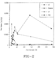
- the pores of the naturally occurring or commercial calcium minerals were predominantly microporous ( ⁇ 5 nm) as seen in Figure 2 .
- the other CaO precursors are Linwood calcium carbonate (LC) and dolomite (DL).
- LC Linwood calcium carbonate
- DL dolomite
- the mesoporous pores would make the sorbent less susceptible to pore pluggage and filling, a phenomenon observed due to the presence of microspores (as seen by Harrison and co-workers). This now leads to almost 100% sorbent conversions.
- PCC and, CaO obtained from PCC were found to have extraordinarily high reactivity towards SO 2 , H 2 S and CO 2 (Ghosh-Dastidar et al., 1996; Chauk et al., 2000; Gupta and Fan, 2002) giving very high conversions.
- Figures 5 and 6 depict the sorption capacity of the sorbent, quantified in kg CO 2 captured/kg sorbent. Theoretically, 56 grams of unsupported CaO sorbent should react with 44 grams of CO 2 corresponding to a maximum CO 2 sorption capacity of 78.6 wt% at 100% conversion. From Figure 5 it is evident that the wt% capacity of the LC based sorbent towards CO 2 capture reduces from 58% in the first cycle to 20% at the end of the 50 th cycle, due to the dominant microporosity in the LC precursor, which makes the structure susceptible to pore pluggage and pore mouth closure (Gupta et al., 2002; Wu et al., 2002).
- Figure 7 depicts graphically the wt% CO 2 capture attained by LC, PCC and a host of other high temperature metal oxide sorbents reported in the literature for multiple CCR cycles (White et al., 2003). While numerous studies have been conducted on a variety of metal oxide based CCR process, a metal oxide that shows consistently high reactivity and sorption capacity over multiple cycles remains to be identified. The experimental conditions used in the studies referred to in Figure 7 are detailed in a table elsewhere (Iyer et al., 2004). The table highlights important process conditions such as carbonation/ calcination temperatures and residence times, number of cycles, sorption capacities, and the CO 2 concentration in the gas mixture during the reaction and regeneration steps.
- PCC-CaO attains a 66.8 wt% increase in 30 minutes and 71.5 wt% after 120 min at the end of the first cycle.
- earlier studies (Gupta et al., 2002) have shown a sorption capacity of about 71 wt% (90% conversion) in a pure CO 2 stream after 60 mins at 650 °C.
- factors like CO 2 concentration, temperature and cycle time play a significant role in determining the sorption capacity for the same sorbent.
- Dolomitic limestone based CCR process yielded a 35 wt% capacity in the first cycle that fell to 11.4 wt% by the 148 th cycle when the carbonation experiments were performed in pure CO 2 at 800 °C and calcination was conducted at 950 °C. They observed a decrease in calcium conversion from 83 % in the 1st cycle to about 69 % in the 10th cycle itself, followed by 27% conversion after 148 cycles (Ortiz et al., 2001).
- Table 1 Structural properties of Calcium based sorbents undergoing vacuum calcination at 750 °C and carbonation at 700 °C.
- SA m2/g
- Pore Volume cc/g
- CaO-1 12.63 0.02409 CC-2 6.5 0.0103
- CaO-2 15.93 0.04008 CC-3 2.361 0.004483
- Figure 8 gives the options for direct and indirect fired calciners to regenerate the CaCO 3 sorbent.
- the fuel in the direct calcination option could also be the hydrogen produced in the plant.
- the heat for calcination could be obtained by H 2 combustion and the steam formed could be easily condensed out.
- CaO calcium oxide
- FIG. 9 shows the relationship between the reaction temperature and the equilibrium partial pressures of H 2 O and CO 2 for the hydration and carbonation reactions.
- a typical gasifier moisture composition ranging from 12-20 atm (P H2O ) the hydration of CaO occurs for all temperatures below 550-575 °C, respectively. By operating above these temperatures, the CaO-hydration can be prevented.
- Figure 9 shows the typical equilibrium CO 2 partial pressures (P CO2 ) as a function of temperature. From the data in Table 2, it can be inferred that the typical P CO2 in the gasifiers ranges from 0.4-4.3 atm for entrained flow (slurry) and entrained flow (dry) gasifier systems respectively. The equilibrium temperatures corresponding to those P CO2 lie in the 830-1000 °C range as shown in Figure 9 . Thus, by operating below these temperatures, we can effect the carbonation of CaO.
- thermodynamic calculations depend on the concentration of moisture in the system as well as the CO 2 in the system.
- the thermodynamics of the sulfidation of CaCO 3 given below is not favorable for H 2 S removal as compared to CaO.
- Sulfidation of CaCO 3 CaCO 3 + H 2 S ⁇ CaS + H 2 O + CO 2
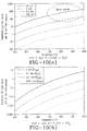
- Figure 10 (a) depicts the equilibrium H 2 S concentrations in ppm for varying moisture concentrations (P H2O ) and 30 atm total pressure.
- the proposed integrated WGS-carbonator reactor system will be operating at near-stoichiometric steam requirement resulting in low concentrations of steam in the reactor system.
- the CO 2 concentration will also be minimal due to the continuous removal of the CO 2 product via carbonation.
- the reactor system will now favor H 2 S removal using CaO at around 600-700 °C.
- Figure 10 shows the thermodynamic equilibrium H 2 S concentration for varying steam concentrations (0.02-20 atm).
- the equilibrium H 2 S concentration corresponds to about 1 ppm.
- the reactor system can achieve CO 2 as well as H 2 S removal while producing a pure H 2 stream.
- the typical gasifier conditions enable H 2 S removal to only 100-300 ppm.
- the concepts of COS capture and HCl capture by calcium oxide in a gas mixture with minimal CO 2 and steam can be explained via Figures 10 (b) and 10 (c) .
- Synthesis gas obtained from the gasification of coal contains chloride impurities in the form of hydrogen chloride which causes severe corrosion in the equipment downstream of the gasifier.
- concentration of hydrogen chloride in the gas stream from the gasifier depends on the type of coal, gasifier, temperature of operation used it typically varies within the range of 50 to 400 ppmv.
- Traditional methods of HCl removal include using a chloride guard which is expensive and can only be operated at temperatures below 450 °C resulting in severe energy penalties.
- CaS Regeneration Steam as well as CO 2 can also react with CaS to form CaO given by the reactions (Turgoden et al., 1973, Ruth et al., 1978) (Adanez, et al, 2001). These reactions can occur in the range of 400-900 °C and will be evaluated in this project.
- the combined carbonation and WGS reaction for enhanced H 2 production was conducted in an integral fixed bed reactor assembly described elsewhere (Gupta et al., 2004).
- Different calcium oxide precursors such as naturally occurring limestone: Linwood Carbonate (LC) and Linwood Hydroxide (LH) in addition to the structurally modified PCC were tested.
- the high temperature shift (HTS) iron oxide catalyst on chromium oxide support was procured from Süd-Chemie, Inc.
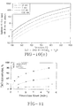
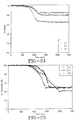
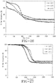
- Figure 12(a) illustrates the CO conversion breakthrough curve for both the PCC and LC sorbent-catalyst systems. It is evident from the figure that the presence of CaO enhances the CO conversion and hence the hydrogen production. In both the systems we observe 100% initial conversion and the system finally reaches steady state. In addition, we observe that PCC-CaO system dominates over the LC-CaO system at any given time demonstrating the superior performance of the PCC sorbent towards hydrogen production.
- Figure 12 (b) describes the nitrogen and steam free product gas compositions for a PCC-HTS system at 600°C. It is clear from this figure that during the initial breakthrough period the system demonstrates the production of a 100% pure hydrogen stream while the CO and CO 2 concentrations are negligible. As the system reaches steady state the CO 2 and H 2 concentrations tend to converge.
- the combined water gas shift reaction and the carbonation reaction were carried out in a fixed bed reactor containing the calcined PCC sorbent and the HTS catalyst.
- the experiments were carried out at two pressures of 1 and 20 bar and this was done to study the performance of the combined reactions in a commercial setup where the fuel gas is typically around 20-30 bar.
- the combined reactions demonstrated a superior performance at 20 bar as compared to ambient pressures, leading to the formation of 100% pure hydrogen during the initial stages of the reaction.
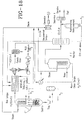
- FIG 16 describes the integration of the proposed hydrogen production process in a typical coal gasifier.
- the syngas from the gasifier flows into the combined "one box" WGS-carbonator reactor where stoichiometric amount of steam is injected along with CaO leading to enhanced WGSR coupled with CO 2 and H 2 S capture in the system.
- the proposed integrated WGS-carbonator reactor system will be operating at near-stoichiometric steam requirement resulting in low concentrations of steam in the reactor system.
- the CO 2 concentration will also be minimal due to the continuous removal of the CO 2 product via carbonation.
- the reactor system will now favor sulfur (H 2 S and COS) removal using CaO at around 500-700 °C. to about 10 ppb--20 ppm.
- the reactor system can achieve CO 2 as well as H 2 S removal while producing a pure H 2 stream.
- the proposed technology has an immense likelihood of success and this evident from the support letters from companies such as Shell Oil, American Electric Power, Sasol etc.
- the proposed technology has several benefits over current technology as it offers a novel integrated one stage process for producing high purity high temperature high-pressure hydrogen with carbon management incorporated in it. Besides, it also includes sulfur removal and halide removal from the system making the process economical and energy efficient.
- the process can be optimized for various configurations such as:
- CO 2 capture technologies induces severe energy losses.
- the parasitic energy consumption which decreases the total power plant capacity, is 30% for the conventional amine scrubbing process while it improves to 28% for the oxy-combustion system (Caul et al., 2005).
- a successful alternative will require the incorporation of effective process integration schemes to minimize the parasitic energy requirement for CO 2 separation.
- One scheme for heat integration is based on the calcium based carbonation-calcination reaction (CCR) process which uses the re-engineered limestone sorbent mentioned earlier at 600-700 °C for efficient and economical CO 2 separation.
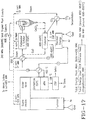
- Figure 17 delineates the heat integration strategies for retrofitting the CCR process to an existing boiler without any significant modifications to the coal-based power plant.
- the flue gas that leaves the economizer of the boiler is routed to the CCR process system for CO 2 capture.
- This flue gas from the economizer (stream 1), is used to combust additional fuel with air to provide heat to the indirect calciner.
- Heat is extracted from the total flue gas mixture (stream 2), which contains all the CO 2 emitted by the entire plant, before it can be sent into the carbonator/sulfator system, to produce high quality steam.
- CO 2 and SO 2 are removed in the carbonator/sulfator system and the CO 2 free flue gas (stream 3), which is at ⁇ 650 °C, is cooled before it is sent into the air pre-heater followed by ESP (electrostatic precipitator).
- the carbonated sorbent, CaCO 3 is sent to the calciner to regenerate the calcium oxide (CaO) sorbent for subsequent cycles while yielding a pure CO 2 stream.
- the sulfated sorbent and fly ash are removed from the system by means of a purge stream. This process is designed to capture both CO 2 and SO 2 simultaneously, rendering it a multi-pollutant control technology.
- the heat of carbonation can be as high as one-third of the total thermal capacity of a power plant.
- steam is generated using high quality heat available from three different sources: (a) carbonator/sulfator (b) hot flue gas after supplying energy to calciner (between 600-850°C) (c) a pure CO 2 stream from calciner at 800-850 °C.
- This steam can be used in a secondary steam turbine system for additional electricity generation or in the existing plant steam cycle by offsetting the boiler load and in driving various feed water pumps in the plant.
- the total parasitic energy consumption of the plant is enormous reduced to 15%, including CO 2 compression (10%), which is half of that of the conventional amine scrubbing process.
- FIG. 18 describes the integration of the proposed hydrogen production process in a typical coal gasifier.
- the syngas from the gasifier flows into the combined "one box" WGS-carbonator reactor where stoichiometric amount of steam is injected along with CaO leading to enhanced WGSR coupled with CO 2 and H 2 S capture in the system.
- the proposed integrated WGS-carbonator reactor system will be operating at near-stoichiometric steam requirement resulting in low concentrations of steam in the reactor system.
- the CO 2 concentration will also be minimal due to the continuous removal of the CO 2 product via carbonation.
- the reactor system will now favor sulfur (H 2 S and COS) removal using CaO at around 500-700 °C to about 10 ppb--20 ppm.
- the reactor system can achieve CO 2 as well as H 2 S removal while producing a pure H 2 stream.
- the proposed technology has several benefits over current technology as it offers a novel integrated one stage process for producing high purity high temperature high-pressure hydrogen with carbon management incorporated in it. Besides, it also includes sulfur removal and halide removal from the system making the process economical and energy efficient.
- the process can be optimized for various configurations such as:
- the gas stream from the WGS reactor and the hydrolysis reactor are mixed together and passed through several gas cleanup units that consist of a mercury removal bed, bulk sulfur removal units, sulfur polishing unit, and CO 2 removal units. After the pollutants are removed, a clean syngas stream with a H 2 to CO ratio of around 2 is obtained which is sent to the F-T reactor for the production of liquid fuel.
- the F-T reactor is capable of converting more than 70% syngas into a wide range of hydrocarbons ranging from methane to wax.
- the products from the F-T reactor are sent to a product upgrader where the high molecular weight hydrocarbons are refined into liquid fuel or naphtha while the low molecular weight fuel gas stream is sent to a power generation block to generate electricity for the air separation unit and other parasitic energy consumption 1,13 .
- expensive gas cleanup units for sulfur and CO 2 removal are needed and the parasitic energy consumption for cooling and reheating the gas stream is very large. This parasitic energy consumption requires the off gases to be burnt in a turbine which reduces the total liquid fuel yield from the coal.
- a H 2 :CO ratio of the desired level can be obtained by converting the C1-C4 hydrocarbons and unconverted syngas produced from the FT reactor and the syngas from the gasifier in an efficient manner, while achieving CO 2 and H 2 S removal in the same reactor system. Since contaminant removal is achieved at high temperatures the parasitic energy requirement is greatly reduced and also the issues related to procurement and deactivation of the sulfur tolerant catalyst for the WGSR are eliminated.
- the unreacted syngas and light hydrocarbons from the FT reactor are mixed with the syngas from the gasifier and sent into the single reactor system which adjusts the ratio of the H 2 :CO in the syngas stream by reforming the hydrocarbons (eqn. (13)) and shifting the syngas (eqn. (14)) in the presence of CaO.
- the concomitant carbonation of the metal oxide (CaO) leading to the formation of the metal carbonate (CaCO 3 ) inceimpulsly drives the equilibrium-limited WGSR and the reforming reaction forward by removing the CO 2 product from the gas mixture(eqn. (15)).
- the metal carbonate can then be regenerated by heating, to give back the metal oxide and a pure CO 2 stream (eqn.
- the calcium looping process aids in:
- the natural gas (NG) is initially split into two parts (a) for feed to the reformer to make hydrogen and (b) fuel for the reformer and steam generator.
- the natural gas feed is them compressed, cleaned of sulfur impurities and is then fed to a performer which operates at lower temperatures and catalytically converts all the C2-C5 streams in the NG to CO 2 or methane.
- the feed now enters the SMR unit at high temperatures which converts the NG to syngas.
- the commercial nickel alumina catalyst is the industry workhorse for SMR. Process.
- the process stream is now rich in CO and H 2 with a H 2 /CO ratio of about 3.
- the stream then undergoes high and low temperature water gas shift reaction (WGSR) where all the CO gets converted to H 2 .
- WGSR water gas shift reaction
- the stream is then fed to a pressure swing adsorption (PSA) unit where all the gases except H 2 get adsorbed in the beds leading to a pure H 2 product stream which can be more than 99.999% pure.
- PSA pressure swing adsorption
- the unconverted CO, CO 2 and CH 4 stream are subsequently desorbed from the PSA unit that forms the fuel stream to reformer burner.
- the drawback of the SMR is the capital cost of the reformer due to the high temperature operation and heat integration requirements due the severe endothermicity of the reaction.
- Other approaches include partial oxidation (POX) where oxygen is used to partially oxidize natural gas to produce synthesis gas. This scheme results in in-situ combustion of the natural gas to provide heat for the reaction.
- Novel system includes autothermal reforming (ATR) which is a combination of partial oxidation and SMR to produce synthesis gas. These approaches result in almost complete methane conversions (95-99%) and better heat integration schemes due to in-situ combustion. While the SMR has better system efficiency of about 80% as compared to 72% for ATR, the capital costs for ATR units are about 75% of that of SMR.
- the SMR process also produces the maximum H 2 per mole of natural gas used.
- incorporation of CO 2 control technology would reduce the process efficiency and increase the capital cost of SMR process making hydrogen production via SMR uneconomical as the price of natural escalates.
- FIG. 20 A simplified schematic of enhanced hydrogen production using steam methane reforming (SMR) coupled integrated with the calcium looping scheme is shown in Figure 20 .
- the reaction scheme which includes SMR, WGSR, carbonation, calcinations and sulfur capture is shown below.
- the drawback of a conventional SMR process is the huge heat requirement due to the endothermic reaction (13) requiring higher temperature operation leading to operating temperatures of about 800-950 °C.
- the integrated indirect heat transfer system coupled with high temperature operation leads to large capital costs for the reformer.
- the carbonation reaction is exothermic which also drives the equilibrium limited WGSR forward at high temperatures.
- the SMR, WGSR and carbonation reactions can be conducted in one single step at a reaction temperature of about 550-700 °C at high operating pressures of 20 atm.
- the overall heat balance for the reactions is almost neutral (-13 kJ/mol) and the process can be achieved at lower temperatures resulting in lower capital costs.
- the process results in complete carbon conversions, lower steam requirement, simultaneous in-situ sulfur removal and integrated CO 2 capture while producing high pressure hydrogen (20 bar). Compression of hydrogen is very expensive and this process obviates the need for first stage H 2 compression.
- the incorporation of the calcium looping scheme results in integration of steam reforming, WGSR, CO 2 capture, sulfur removal and hydrogen separation in "one single step” while reducing excess steam requirement and producing high purity high pressure hydrogen resulting in improved process efficiency and reduced capital costs.
- the calcium looping process simplifies the production of H 2 by integrating the water gas shift reaction (WGSR) with in-situ carbon dioxide, sulfur and hydrogen halide removal from the synthesis gas at high temperatures in a single stage reactor process while eliminating the need for WGSR catalyst requirement.
- This technology provides a "one box" mode of operation for production of high purity hydrogen with integrated CO 2 , sulfur and chloride capture that integrates WGSR, hydrogen separation (PSA/membranes), CO 2 capture, and sulfur removal in one consolidated unit.
- Another advantage is that in addition to generating a pure hydrogen stream, it is also capable of adjusting the H 2 to CO ratio in the outlet to the required level while removing sulfur very low levels thus making it an attractive scheme for the production of liquid fuels by the Fisher Tropsch's reaction.
- This integrated "one box” process depicts the potential to achieve higher system efficiencies with lower overall footprint by combining different process units in one stage.
- the envisioned system has the flexibility and the potential to produce hydrogen of different purity levels by reducing the amount of WGS catalyst and reducing the excess steam requirement.
- This novel process which enables high temperature operation can also be deployed for reactive CO 2 capture from flue gases.
- the technology increases the overall conversion and process efficiency for various process applications.
- a high reactivity mesoporous calcium oxide sorbent is described in US Patents 5,779,464 and 7,067,456 B2 .
- the disclosed embodiments combine various unit operations (reforming, WGS, CO 2 capture and H 2 S removal) into a single reactor system and to improve the overall efficiency of the coal to liquid technology by using the calcium looping process.
- the specific objectives are as follows a)To convert all the C1-C4 hydrocarbons and unconverted syngas from the FT process, and syngas from the gasifier, into a 2:1 H 2 :CO stream by shifting the equilibrium of the WGS and reforming reaction in the forward direction by removing the CO 2 product insitu, b) To achieve simultaneous CO 2 and H 2 S capture at high temperatures to ppb levels, c) To produce a sequestration ready CO 2 stream, d) To reduce the excess steam requirement which aids in higher levels of H 2 S removal, e) To reform and reuse all the C1-C4 hydrocarbons produced from the FT reaction to produce more liquid fuel than the conventional process, for the same amount of coal consumed.
- a conventional coal to liquid plant consists of a gasifier which produces the syngas.
- the H 2 /CO ratio of the syngas is around 0.63, which is much lower than the ratio of ⁇ 2, required for liquid fuel production.
- part of the syngas is introduced to a WGS reactor to be shifted into H 2 . Since the gas stream contains sulfur impurities a sulfur tolerant WGS catalyst is used, which is expensive.
- the rest of the syngas stream passes through a hydrolysis unit where the COS is converted into H 2 S.
- the gas stream from the WGS reactor and the hydrolysis reactor are mixed together and passed through several gas cleanup units that consist of a mercury removal bed, bulk sulfur removal units, sulfur polishing unit, and CO 2 removal units. After the pollutants are removed, a clean syngas stream with a H 2 to CO ratio of around 2 is obtained which is sent to the F-T reactor for the production of liquid fuel.
- the F-T reactor is capable of converting more than 70% syngas into a wide range of hydrocarbons ranging from methane to wax.
- the products from the F-T reactor are sent to a product upgrader where the high molecular weight hydrocarbons are refined into liquid fuel or naphtha while the low molecular weight fuel gas stream is sent to a power generation block to generate electricity for the air separation unit and other parasitic energy consumption 1,13 .
- expensive gas cleanup units for sulfur and CO 2 removal are needed and the parasitic energy consumption for cooling and reheating the gas stream is very large. This parasitic energy consumption requires the off gases to be burnt in a turbine which reduces the total liquid fuel yield from the coal.
- a H 2 : CO ratio of the desired level can be obtained by converting the C1-C4 hydrocarbons and unconverted syngas produced from the FT reactor and the syngas from the gasifier in an efficient manner, while achieving CO 2 and H 2 S removal in the same reactor system. Since contaminant removal is achieved at high temperatures the parasitic energy requirement is greatly reduced and also the issues related to procurement and deactivation of the sulfur tolerant catalyst for the WGSR are eliminated.
- the unreacted syngas and light hydrocarbons from the FT reactor are mixed with the syngas from the gasifier and sent into the single reactor system which adjusts the ratio of the H 2 :CO in the syngas stream by reforming the hydrocarbons (eqn. (1)) and shifting the syngas (eqn. (2)) in the presence of CaO.
- the concomitant carbonation of the metal oxide (CaO) leading to the formation of the metal carbonate (CaCO 3 ) inceimpulsly drives the equilibrium-limited WGSR and the reforming reaction forward by removing the CO 2 product from the gas mixture(eqn. (3)).
- the metal carbonate can then be regenerated by heating, to give back the metal oxide and a pure CO 2 stream (eqn. (5)).
- the mixture of gases from the FT reactor and the gasifier are mixed and sent into a single reactor which contains a mixture of reforming catalyst and CaO.
- the steam injection rate and the calcium injection rate will be optimized such that the C1-C4 compounds are reformed and the syngas is shifted to the required extent to obtain a H 2 :CO ratio of 2.
- the single reactor contains a mixture of pre-reforming catalyst and sorbent which convert the C2-C4 hydrocarbons into H 2 and CO 2 due to the high selectivity of the catalyst and the CO 2 is removed by the CaO.
- the pre-reforming catalyst is resistant to carbon deposition, low quantities of steam injection can be used, which is beneficial for H 2 S removal. Also since the pre-reforming catalyst operates at lower temperatures of 500-600C, which is the optimum temperature for carbonation and sulfidation, the amount of solid circulation is very low, making this scheme very attractive in all respects. Since methane is not reformed by the pre-reforming catalyst either a purge stream can be removed and used for power generation or a fixed bed of the reforming catalyst can be used downstream in the same reactor system. In the third scenario the reactor contains only calcium oxide sorbent which accelerates the reforming and the WGSR in the non catalytic mode, while removing the CO 2 and H 2 S impurities. This option is very attractive as it obviates the need for a catalyst which simplifies the operation of the reactor system and reduces the costs associated with the deactivation of the catalyst.
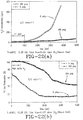
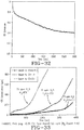
- Figure 22(a) illustrates the break through curves in H 2 S composition for experiments conducted at ambient pressure and 15 atm. It can be seen that in the prebreakthrough region of the curve the calcium oxide sorbent undergoes sulfidation removing H 2 S to levels of less than 1 ppm at ambient pressure. At a higher pressure of 15 atm, lower levels of H 2 S in the ppb range were detected in the outlet stream. This clearly shows that when stoichiometric quantity of steam is used very high H 2 S removal is achieved in the system.
- Figure 22(a) illustrates the break through curve for H 2 composition in the same experiment. A very distinct pre breakthrough region is observed in the curve which shows that the CaO is very effective in driving the water gas shift reaction in the forward direction.
Landscapes
- Chemical & Material Sciences (AREA)
- Organic Chemistry (AREA)
- Chemical Kinetics & Catalysis (AREA)
- Engineering & Computer Science (AREA)
- Combustion & Propulsion (AREA)
- Inorganic Chemistry (AREA)
- Health & Medical Sciences (AREA)
- General Health & Medical Sciences (AREA)
- General Chemical & Material Sciences (AREA)
- Oil, Petroleum & Natural Gas (AREA)
- Hydrogen, Water And Hydrids (AREA)
- Solid-Sorbent Or Filter-Aiding Compositions (AREA)
Description
- The disclosed embodiments are in the field of hydrogen production. Mahesh Iyer et al discloses enhanced hydrogen production integrated with CO2 separation in a single-stage reactor (internet citation, (20050310), pages 1 - 18, url: http://www.osti.gov/bridge/product.biblio.jsp?query_id=0&page=0&osti_id=838222). H Gupta et al discloses enhanced hydrogen production integrated with CO2 separation in a single-stage reactor (DOE annual technical progress report, (20050310), pages 1 - 30, url: http://www.osti.gov/energycitations/servlets/purl/838225-oekae3/native/838225.pdf). J Abbasian et al discloses the effect of HCL on sulfidation of calcium oxide (Chemical Engineering Science, vol. 48, no. 15, pages 2689 - 2695). Gupta H et al discloses carbonation-calcination cycle using high reactivity calcium oxide for carbon dioxide separation from flue gas (Industrial & Engineering Chemistry Research, American Chemical Society, US, (20021107), vol. 41, no. 16, doi:10.1021/ie010867I, ISSN 0888-5885, pages 4035 -4042).
- The disclosed embodiments include a process for producing hydrogen, comprising the steps of: (a) gasifying a fuel into a raw synthesis gas comprising CO, hydrogen, steam and sulfur and halide contaminants in the form of H2S, COS and HX, where X is a halide; (b) injecting said raw synthesis gas, CaO and steam into a water gas shift reactor (WGSR), wherein said raw synthesis gas transforms into a shifted gas without a catalyst; allowing said shifted gas to react with said CaO in said WGSR so as to remove CO2, sulfur and halides in a solid-phase calcium-containing product comprising CaCO3, CaS and CaX2; (c) separating the solid-phase calcium-containing product from an enriched gaseous hydrogen product; and (d) regenerating the CaO by calcining the solid-phase calcium-containing product at a condition selected from the group consisting of: in the presence of steam, in the presence of CO2, in the presence of synthesis gas, in the presence of H2 and O2, under partial vacuum, and combinations thereof.
- The fuel could be coal, biomass, oil sands, coke, tar, wax oil shales, or combinations of these materials.
- The steam injected is in the range of from about the stoichiometric requirement to about 3 times the stoichiometric requirement.
- In one embodiment, the enriched hydrogen product has a purity of at least 60%. In one embodiment, the H2:CO ratio of the enriched hydrogen product is in the range of from about 0.5:1 to about 1000:1. In some embodiments the enriched hydrogen product has a purity in the range of from about 70% to about 99.99%, at temperature in the range of from about 400 - 1000 C, and a pressure in the range of from about 1 to about 100 atmospheres.
- The WGSR may be of a type selected from the group consisting of: fixed bed reactors, fluidized bed reactors, entrained flow reactors, moving bed reactors rotary kilns, or combinations thereof. Additionally, the calcinations step may be performed in a calcinations reactor of a type selected from the group consisting of: fixed bed reactors, fluidized bed reactors, entrained flow reactors, moving bed reactors rotary kilns, or combinations thereof.
- The WGSR does not have a catalyst disposed therein. As such the WGSR operates at a temperature in the range of from about 550 - 750 C, in the pressure range of from about 1 to about 60 atm, it is preferred that the WGSR reactor operate in a temperature range of from about 600 - 700C and at a pressure in the range of from about 20 to about 30 atm. In some embodiments, the enriched hydrogen product is 99% pure when 3 times the stoichiometric steam requirement is used. At the stoichiometric steam requirement the process produces an enriched hydrogen product that is 90% pure. In another catalytic embodiment, the enriched hydrogen product has a H2/Co ration of at least 2.5 and a maximum sulfur (H2S/COS) concentration of less than 10 ppm using only the stoichiometric requirement of steam.
- In some disclosures which are not according to the present invention, a catalyst may be used in the WGSR. A suitable high temperature shift catalyst which may include: Fe, Cu, Co, Mo, W, Cs, Pt, Ph, Pd, and other precious metal catalysts or their oxides or sulfides or combinations thereof. Suitable supports for use with the foregoing high temperature shift catalysts include: Cr2O3, ZnO, MgO, ceria, alumina, silica, zirconia and combinations thereof.
- A WGSR reactor with a catalyst operates in the temperature range of from about 550 - 750 C and at a pressure in the range of from about 1 to about 100 atm. It is preferred that the WGSR reactor operate in the temperature range of from about 600 - 700 C and at a pressure of from about 20 to about 30 amt. When a catalyst is used the enriched hydrogen product may achieve 99.99% purity when 3x the stoichiometric requirement of steam is used in the WGSR. The enriched hydrogen product may achieve 98% purity when the stoichiometric requirement of steam is used. Some embodiments may attain a purity of at least 80% with a maximum sulfur (H2S/COS) concentration of less than 10 ppm when 3X the stoichiometric requirement of steam is used and at least 70% purity with a maximum sulfur concentration of less than 1 ppm when the stoichiometric requirement of steam is used.
- The process may also comprise the step of (e) recycling at least a portion of a product stream from a Fischer-Tropsch reactor, fed by the WGSR, so as to introduce a chemical species selected from the group consisting of: methane, C1 - C4 hydrocarbons, CO, hydrogen and combinations thereof back into the WGSR.
- In all embodiments, the CaO may have a surface area of at least 12.0 m2/g and a pore volume of at least 0.015 cm3/g, said CaO having a sorption capacity of at least about 70 grams of CO2 per kilogram of CaO.
- The CaO may be provided in any usable form including, but not limited to, pellets, granules, fines, monoliths and combinations thereof. The CaO may be obtained by processing chicken eggshells.
- Although the regeneration of CaO step may be performed any functional process, it is preferred that it is conducted by a process selected from the group consisting of: (a) calcining in the presence of steam and/or CO2 and/or H2 with O2, and/or synthesis gas with O2 and/or under partial vacuum or combinations thereof; (b) a process in which the heat is added to the calciner using steam and a combination of calciner fuel and oxidant; (c) a process in which the calciner fuel is H2 or natural gas or synthesis gas or coal or combinations thereof; (d) a process in which the oxidant is air or oxygen or combinations thereof; (e) a process in which heat is provided to the calciner directly or indirectly; (f) calciner reactor temperatures ranging from about 700 - 1100 C; and (a process for adjusting the calciner temperature by modifying the CaO to CaCO3 ratio in the calciner. The gas phase product from the calciner may comprise pure CO2 and could also contain trace amounts of H2S.
- The disclosure also includes a process for producing hydrogen, comprising the steps of: (a) reforming a gaseous hydrocarbon fuel in the presence of CaO and steam to remove CO2, sulfur and halide contaminants in the form of H2S, COS and HX, where X is a halide, in a solid-phase calcium-containing product comprising CaCO3, CaS and CaX2, thereby producing a mixture of CO and hydrogen; (b) separating the solid-phase calcium-containing product from an enriched gaseous hydrogen product; and (c) regenerating the CaO by calcining the solid-phase calcium-containing product at a condition selected from the group consisting of: in the presence of steam, in the presence of CO2, in the presence of synthesis gas, in the presence of H2 and O2, under partial vacuum, and combinations thereof.
- The gaseous fuel may be natural gas, C1 - C4 hydrocarbons, or mixtures thereof. The reforming step may involve the introduction of CO2, so called dry reforming.
- The reforming step may involve a reforming catalyst. Suitable reforming catalysts include those comprising: Ni, Pt, Rh, Pd, Ru, W, Mo, their oxide or carbides or sulfides. The reforming catalyst may use a support. Suitable supports for use with the foregoing reforming or pre-reforming catalysts include: alumina, silica, titania, zirconia, and combinations thereof. It is preferred that the reforming catalyst is sulfur intolerant.
- The reforming operation may occur in a temperature range of from about 550 to about 750 C and at a pressure in the range of from about 1 to about 60 atm. Preferably, it operates in the temperature range of from about 600 to about 700 C and at a pressure in the range of from about 20 to about 30 atm.
- The enriched hydrogen product produced may be as pure as 99.9 % when 3X the stoichiometric requirement of steam is used and 95% pure when the stoichiometric requirement of steam is used.
- This process may additionally comprise the step of: (d) recycling at least a portion of a product stream from a Fischer-Tropsch reactor, fed by the reformer, so as to introduce a chemical species selected from the group consisting of: methane, C1 - C4 hydrocarbons, CO, hydrogen and combinations thereof back into the reformer.
- In all embodiments, the CaO may have a surface area of at least 12.0 m2/g and a pore volume of at least 0.015 cm3/g, said CaO having a sorption capacity of at least about 70 grams of CO2 per kilogram of CaO.
- The CaO may be provided in any usable form including, but not limited to, pellets, granules, fines, monoliths and combinations thereof. The CaO may be obtained by processing chicken eggshells.
- When a catalyst is used the enriched hydrogen product may achieve 99.99% purity when 3x the stoichiometric requirement of steam is used. The enriched hydrogen product may achieve 98% purity when the stoichiometric requirement of steam is used. Some embodiments may attain a purity of at least 80% with a maximum sulfur (H2S/COS) concentration of less than 10 ppm when 3X the stoichiometric requirement of steam is used and at least 70% purity with a maximum sulfur concentration of less than 1 ppm when the stoichiometric requirement of steam is used. The process allows for a hydrogen purity of at least 80% with a maximum sulfur (H2S/COS) concentration of less than 10 ppm when 3X the stoichiometric requirement of steam is used and at least 70% purity with a maximum sulfur concentration of less than 1 ppm when the stoichiometric requirement of steam is used.
- Another process which is not according to the present invention is disclosed herein for producing hydrogen, comprising the steps of: (a) at least partially oxidizing a fuel into a raw gas comprising CO, hydrogen, steam and sulfur and halide contaminants in the form of H2S, COS and HX, where X is a halide; (b) passing the raw gas through a water gas shift reactor (WGSR) into which CaO and steam are injected, the CaO reacting with the shifted gas to remove CO2, sulfur and halides in a solid-phase calcium-containing product comprising CaCO3, CaS and CaX2; (c) separating the solid-phase calcium-containing product from an enriched gaseous hydrogen product; and (d) regenerating the CaO by calcining the solid-phase calcium-containing product at a condition selected from the group consisting of: in the presence of steam, in the presence of CO2, in the presence of synthesis gas, in the presence of H2 and O2, under partial vacuum, and combinations thereof.
- In all embodiments, the CaO may have a surface area of at least 12.0 m2/g and a pore volume of at least 0.015 cm3/g, said CaO having a sorption capacity of at least about 70 grams of CO2 per kilogram of CaO.
- The CaO may be provided in any usable form including, but not limited to, pellets, granules, fine, monoliths and combinations thereof. The CaO may be obtained by processing chicken eggshells.
- Although the steam may be injected into the WGSR in any functional quantity, it is preferred that the steam injected is in the range of from about the stoichiometric requirement to about 3 times the stoichiometric requirement.
- The WGSR may be of a type selected from the group consisting of: fixed bed reactors, fluidized bed reactors, entrained flow reactors, moving bed reactors rotary kilns, or combinations thereof. Additionally, the calcinations step may be performed in a calcinations reactor of a type selected from the group consisting of: fixed bed reactors, fluidized bed reactors, entrained flow reactors, moving bed reactors rotary kilns, or combinations thereof.
- The WGSR does not have a catalyst disposed therein. As such the WGSR operates at a temperature in the range of from about 550 - 750 C, in the pressure range of from about 1 to about 60 atm, it is preferred that the WGSR reactor operate in a temperature range of from about 600 - 700C and at a pressure in the range of from about 20 to about 30 atm. In some embodiments, the enriched hydrogen product is 99% pure when 3 times the stoichiometric steam requirement is used. At the stoichiometric steam requirement the process produces an enriched hydrogen product that is 90% pure. In another catalytic embodiment, the enriched hydrogen product has a H2/CO ratio of at least 2.5 and a maximum sulfur (H2S/COS) concentration of less than 10 ppm using only the stoichiometric requirement of steam.
- In some disclosures which are not according to the present invention, a catalyst may be used in the WGSR. A suitable high temperature shift catalyst which may include: Fe, Cu, Co, Mo, W, Cs, Pt, Ph, Pd, and other precious metal catalysts or their oxides or sulfides or combinations thereof. Suitable supports for use with the foregoing high temperature shift catalysts include: Cr2O3, ZnO, MgO, ceria, alumina, silica, zirconia and combinations thereof.
- A WGSR reactor with a catalyst operates in the temperature range of from about 550 - 750 C and at a pressure in the range of from about 1 to about 100 atm. It is preferred that the WGSR reactor operate in the temperature range of from about 600 - 700 C and at a pressure of from about 20 to about 30 atm. When a catalyst is used the enriched hydrogen product may achieve 99.99% purity when 3x the stoichiometric requirement of steam is used in the WGSR. The enriched hydrogen product may achieve 98% purity when the stoichiometric requirement of steam is used. Some embodiments may attain a purity of at least 80% with a maximum sulfur (H2S/COS) concentration of less than 10 ppm when 3X the stoichiometric requirement of steam is used and at least 70% purity with a maximum sulfur concentration of less than 1 ppm when the stoichiometric requirement of steam is used.
-
-
Figure 1 shows the effect of concentrations of different surface modifiers on the zeta potential and specific surface area of the sorbent (a) Ligno-sulfonate (b) Dispex N40V (c) Dispex A40 (adapted from Agnihotri et al., 1999). -
Figure 2 provides pPore size distributions for various calcium sorbents (Gupta and Fan, 2002). -
Figure 3 shows the carbonation reactions of CaO obtained from different precursors at 650 °C (adapted from Gupta and Fan, 2002). -
Figure 4 presents the carbonation reactions of PCC-CaO at different temperatures (Gupta and Fan, 2002). -
Figure 5 provides the extended Calcination-Carbonation cycles with Linwood Carbonate (LC) fines at 700 °C in a TGA in a 10% CO2 stream (Iyer et al., 2004). -
Figure 6 provides the extended Calcination- Carbonation cycles with Precipitated Calcium (PCC) fines at 700 °C in a TGA in a 10% CO2 stream (Iyer et al., 2004). -
Figure 7 shows the CO2 capture capacity of various high temperature sorbents over multiple carbonation-regeneration cycles (alyer et al., 2004; bWhite et al., 2003; Kato et al., 2002; cKato et al., 1999; dBarker 1973; eOrtiz 2001; fBarker 1974) (Iyer et al., 2004). -
Figure 8 illustrates the direct and indirect fired calcination options for designing a calciner. -
Figure 9 provides thermodynamic data for predicting the temperature zones for hydration and carbonation of CaO in a fuel gas mixture. -
Figure 10(a) provides thermodynamic data for predicting the equilibrium H2S concentration for CaO sulfidation with varying steam concentration (PTotal = 30 atm). -
Figure 10(b) provides thermodynamic data for predicting the equilibrium COS carbonyl sulfide concentration for CaO sulfidation with varying CO2 concentration (PTotal = 30 atm). -
Figure 10(c) provides thermodynamic data for predicting the equilibrium HCl concentration for CaO reaction with HCl with varying steam concentration (PTotal = 30 atm). -
Figure 11 shows the reactivity of different CaO sorbents towards H2S removal. -
Figure 12 (a) is a comparison of breakthrough curves depicting CO conversion for PCC-HTS and LC-HTS systems. -
Figure 12(b) shows the gas composition during the combined WGS carbonation reactions using PCC-HTS systems (T = 600 °C, 10.3% CO, 31 % H2O, Total flow = 0.725 slpm). -
Figure 13 is a comparison of H2 gas composition at 1 and 20 bar for a 3:1 steam : CO ratio. -
Figure 14(a) is a comparison of CO conversion for different steam : CO ratios at 1 bar. -
Figure 14(b) is a comparison of CO conversion for different steam : CO ratios at 20 bar. -
Figure 15 (a) shows the outlet gas composition from the reactor at 650°C and 20 bar. -
Figure 15(b) provides the conversion achieved at 650°C and 20 bar. -
Figure 16 presents a conceptual flowsheet depicting integration of various units in the Calcium Looping Processes for H2 generation in typical coal-gasifier facility. -
Figure 17 presents a conceptual schematic of Carbonation-Calcination Reaction (CCR) process integration in a 300 MWe coal fired power plant depicting heat integration strategies (Fan and Iyer, 2006). -
Figure 18 illustrates a calcium looping system integrated in a coal to liquid plant. -
Figure 19 provides a conventional hydrogen production from Steam Methane reforming and pressure swing adsorption. -
Figure 20 is a schematic representation of calcium looping integrated with SMR to produce high purity hydrogen. -
Figure 21 is a comparison of the CO2 capture capacity for various sorbents. -
Figure 22(a) shows the H2S concentration in the outlet gas stream with change in pressure. -
Figure 22(b) shows the H2 gas composition (T = 600 °C, 10.3% CO,S/C : 1:1, H2S=5000ppm, Total flow = 0.725 slpm). -
Figure 23 illustrates the effect of steam:CO ratio on CO conversion during the combined WGS carbonation reaction using PCC-HTS system (T = 650 °C, P= 0psig, 10.3% CO, Total flow = 0.725 slpm). -
Figure 24 illustrates the effect of steam:CO ratio on CO conversion during the combined WGS carbonation reaction using PCC-HTS system (T = 650 °C, P= 150psig, 10.3%CO, Total flow = 0.725 slpm). -
Figure 25 shows the effect of steam :CO ratio on CO conversion during the combined WGS carbonation reaction using PCC-HTS system (T = 650 °C, P= 300psig, 10.3%CO, Total flow = 0.725 slpm). -
Figure 26 shows the effect of steam:CO ratio on the purity of hydrogen produced during the combined WGS carbonation reaction using PCC-HTS system (T = 650 °C, P=0psig, 10.3% CO, Total flow = 0.725 slpm). -
Figure 27 illustrates the effect of steam:CO ratio on the purity of hydrogen produced during the combined WGS carbonation reaction using PCC-HTS system (T = 650 °C, P= 150psig, 10.3% CO, Total flow = 0.725 slpm). -
Figure 28 shows the effect of steam:CO ratio on the purity of hydrogen produced during the combined WGS carbonation reaction using PCC-HTS system (T = 650 °C, P= 300psig, 10.3% CO, Total flow = 0.725 slpm). -
Figure 29 shows the effect of steam:CO ratio on CO conversion during the combined WGS carbonation reaction using PCC sorbent without catalyst (T = 650 °C, P= 300psig, 10.3% CO, Total flow = 0.725 slpm). -
Figure 30 shows the effect of steam:CO ratio on purity of hydrogen produced during the combined WGS carbonation reaction using PCC sorbent without catalyst (T = 650 °C, P= 300psig, 10.3% CO, Total flow = 0.725 slpm). -
Figure 31 illustrates the real time nitrogen and steam free gas composition at the outlet of the reactor system during the combined WGS-carbonation reaction using PCC sorbent without catalyst(T = 650 °C, P=0psig, 10.3% CO, 10.3% H2O, Total flow = 0.725 slpm). -
Figure 32 presents the CO conversion in the reactor system during the combined WGS-carbonation reaction using PCC sorbent without catalyst (T = 650 °C, P=0psig, 10.3% CO, 10.3% H2O, Total flow = 0.725 slpm). -
Figure 33 shows the effect of steam:CO ratio on the concentration of H2S in the outlet of the reactor during the combined WGS carbonation reaction with insitu H2S removal using PCC sorbent without catalyst (T = 600 °C, P= Opsig, 10.3% CO, Total flow = 0.725 slpm). -
Figure 34 shows the real time nitrogen and steam free gas composition at the outlet of the reactor system during the combined WGS-carbonation reaction with insitu H2S removal using PCC sorbent without catalyst (T = 600 °C, P= 0 psig, 10.3% CO, 31% H2O, Total flow = 0.725 slpm). -
Figure 35 shows the real time nitrogen and steam free gas composition at the outlet of the reactor system during the combined WGS-carbonation reaction with insitu H2S removal using PCC sorbent without catalyst (T = 600 °C, P= 0 psig, 10.3% CO, 10.3% H2O, Total flow = 0.725 slpm). -
Figure 36 provides the real time nitrogen and steam free gas composition at the outlet of the reactor system during the combined WGS-carbonation reaction with insitu H2S removal using PCC sorbent without catalyst (T = 600 °C, P= 0 psig, 10.3% CO, 7.73% H2O, Total flow = 0.725 slpm). -
Figure 37 shows the effect of steam:CO ratio on CO conversion during the combined WGS carbonation reaction with insitu H2S removal using PCC sorbent without catalyst (T = 600 °C, P= 0psig, 10.3% CO, Total flow = 0.725 slpm). - In accordance with the foregoing summary, the following presents a detailed description of the preferred embodiments of the invention that is currently considered to be the best mode.
- Enhancement in the production of high purity hydrogen (H2) from synthesis gas, obtained by coal gasification, is limited by the thermodynamics of the water-gas shift reaction (WGSR). However, this constraint can be overcome by concurrent WGSR and carbonation (of calcium oxide) reaction to enhance H2 production. The carbonation of any typical metal oxide (eg. calcium oxide) forming metal carbonate (eg. calcium carbonate) incessantly drives the equilibrium-limited WGSR forward by removing the carbon dioxide (CO2) product from the reaction mixture. The metal carbonate (calcium carbonate) can be separately calcined to yield a pure CO2 stream for its subsequent sequestration and the calcium oxide recycled back. This calcium looping scheme not only improves the hydrogen yield and purity but also integrates a CO2 management scheme and gas cleanup in the hydrogen production process.
- The proposed scheme simplifies high purity H2 production by integrating the water gas shift reaction (WGSR) with in-situ CO2, sulfur (H2S + COS) and hydrogen halide removal from the synthesis gas at high temperatures in a single stage reactor process while eliminating the need for WGS catalyst requirement. We have identified our high reactivity OSU patented, mesoporous calcium oxide sorbent for the in-situ CO2 capture as well as H2S/COS and halides (HCI/HBr etc) removal. The morphological properties of our patented calcium sorbent (PCC) can be tailored using surface modifiers to demonstrate a high CO2 capture capacity of about 70% by weight (∼700g of CO2/kg sorbent), yield a high calcium conversion of above 80% while removing H2S at high temperatures (700-900 °C) and producing H2 with purity greater than 95% without the WGS catalyst. The process highlights include:
- (1) reduction in excess steam requirement and for operating at near-stoichiometric steam consumption
- (2) simultaneous removal of CO2 as well as sulfur (H2S + COS) and halides (HCI/HBr etc) impurities
- (3) production of either a 90-95% H2 stream (without WGS catalyst) or a 99+% high purity H2 stream (with WGS catalyst) at high temperatures (400-1000 °C) and pressures (1-40 atmospheres). The H2 concentrations can vary all the way from 60 to 99+ % purity.
- (4) Flexibility in carbon monoxide conversion to produce H2:CO ratios of varying composition which can range from 0.5 to 20, while capturing sulfur and halide impurities resulting in minimal impurity levels in the product gas stream (ppm to ppb levels), suitable for fuels/chemical synthesis from Fischer Tropsch reactions.
- (5) production of a sequestrable CO2 stream by spent sorbent regeneration at high temperatures (700-1100°C). Sorbent regeneration includes calcining the carbonated sorbent (CaCO3) using H2 and oxygen and/or steam to generated calcium oxide. The calcium sulfide sorbent can be regenerated to calcium oxide by treatment with steam and carbon dioxide. The calcium halide (for example calcium chloride) can be regenerated to calcium oxide using hydrogen and oxygen mixtures.
- The various reaction schemes being integrated in the process are:
-
Coal Gasification: CxHyO + H2O → xCO + (y/2+1) H2 WGSR: CO + H2O ⇔ H2 + CO2 Carbonation: CaO + CO2 → CaCO3 Sulfur capture (H2S): CaO + H2S → CaS + H2O Sulfur capture (COS): CaO + COS → CaS + CO2 Halide capture (HCl): CaO + 2HCl → CaCl2 + H2O -
CaCO3 regeneration: CaCO3 → CaO + CO2 CaS regeneration: CaS + H2O + CO2 → CaCO3 + H2S Halide (CaCl2) regeneration: CaCl2 + H2 + ½ O2 → CaO + 2HCl - The proposed technology aims on enhancing H2 production, from a typical coal gasification stream, by integrating the water gas shift reaction (WGSR) through in-situ CO2, sulfur and hydrogen halide removal from the synthesis gas at high temperatures in a single stage reactor process while eliminating the need for a WGS catalyst. Thus, this integrated process indeed consolidates several unit operations viz. WGS reactor, CO2 capture, sulfur removal, halide removal and hydrogen production in one process module, downstream of a coal gasification system to produce a pure hydrogen stream. The goals of this calcium looping process are (1) to reduce the excess steam requirement and operate at near-stoichiometric steam consumption (2) to simultaneously remove CO2 as well as sulfur and halides (3) to produce a sequestrable CO2 stream by sorbent regeneration, (4) to produce either a 90-95% H2 stream (without WGS catalyst) or a 99+% high purity H2 stream (with WGS catalyst) at high temperatures and pressures. This integrated "one box" process depicts the potential to achieve higher system efficiencies with lower overall footprint by combining different process units in one stage. The envisioned system has the flexibility and the potential to produce hydrogen of different purity levels by reducing the amount of WGS catalyst and reducing the excess steam requirement. This novel process removes the need for hydrogen separation membranes and the high temperature operation increases the overall conversion and process efficiency.
- Hydrogen is a useful fuel and a feedstock for various other fuels, processes and commodities. The future role of hydrogen in the world energy cycle might gain critical significance. Economical hydrogen production from fossil fuels in a sequestration ready manner remains a challenge. It is envisaged that hydrogen would be used to carry the energy contained in fossil fuels for numerous mobile applications while the CO2 generated from the fossil fuels would be safely sequestered from these large local facilities. The major processes for hydrogen production from fossil fuels involve steam reforming of methane (SMR), coal gasification, catalytic cracking of natural gas, and partial oxidation of heavy oils (Rosen and Scott, 1998; Rosen, 1996).
Coal Gasification: CxHy + H2O → xCO + (½ + 1) H2 (1) Steam Methane Reforming (SMR): CH4 + H2O → CO + 3H2 (2) Partial oxidation of hydrocarbons: CxHy + O2 → xCO + (½ + 1) H2 (3) - The gases coming from these reactions are then sent to the downstream water gas shift (WGS) reactors to enhance the hydrogen production by the WGS reaction given as:
(WGSR) CO + H2O <=> CO2 + H2 (ΔH = - 40.6 kJ/mol) --- (4) - To obtain high purity H2, the WGS reaction is generally carried out in two stages for: (1) high temperature shift (250-500 °C) using iron catalysts and (2) low temperature shift (210-270 °C) using copper-based catalysts (Gerhartz, 1993; Bohlbro, 1969). The shortcomings of the current reaction scheme are:
- 1. Copper based catalysts are extremely intolerant to small quantities of sulfur (< 0.1ppm) and hence the fuel gases need to be desulfurized upstream of the WGS reactor.
- 2. A high steam:CO ratio is required to enhance CO conversion and the consequent hydrogen production. The steam to CO ratio at 550 °C can be as high as 50 in a single-stage operation or 7.5 for a more expensive dual-stage process to obtain 99.5 % pure H2 (David, 1980). For example, to lower the CO content of the typical fuel gas from 45 % (inlet) to 3% (outlet) a total steam addition of 1.18 kg/m3 of the gas is required, at a total pressure of 60 bars and 410 °C (Gerhartz, 1993).
- 3. While higher temperature enhances the kinetics of the WGSR, thermodynamics adversely affects the hydrogen production due to the equilibrium limitation of the WGSR with the H2 yield falling with rising temperature.
- An effective technique to shift the WGSR to the right for enhanced hydrogen generation has been to remove hydrogen from the reaction mixture. This premise has lead to the development of hydrogen separation membranes. However, membranes cannot completely remove hydrogen from the mixture and there is also the effect of a considerable pressure drop across them (Roark, et al 2002). In addition, any remaining hydrogen in the main stream would dilute CO2 and would lead to poor process economics.
- The other option is to remove the CO2 from the reaction gas mixture. Various solvents such as amines, Selexol, Rectisol etc have been used to scrub the CO2 from the WGS reaction gas mixture (Steigel and Ramezan, 2006) between two stages. However, these solvents operate at ambient temperatures and consequently this method involves severe energy penalties due to cooling and reheating of the reaction gas mixture. Hence, high temperature CO2 membranes were developed (US DOE, 2005) which operate in the same temperature range as that of the WGSR. Thus the development of these membranes has led to the concept of membrane reactors. However, the use of these membranes leads to the development of a pressure drop and the costs associates with these membranes make the overall process expensive.
- There are several processes that enhance hydrogen production using limestone sorbents such as the ZECA process and the HyPr-RING Process (Lin et al., 2002; Ziock et al., 2001). However, these processes operate at very high pressures (12-100 MPa) to produce H2, which is not economically viable. On the other hand processes such as HyPr-RING result in the gasification of coal with in-situ CO2 capture using CaO/Ca(OH)2 systems (Lin et al., 2005). However, these systems operate at very high pressures (70 bar) and require excess steam and produce only 91% pure hydrogen. In addition, there have been several reports on sorption enhanced hydrogen production by coupling SMR and in-situ CO2 capture using a sorbent (Hufton et al., 1999; Akiti 2004; Balasubramanian et al., 1999; Lopez Ortiz and Harrison, 2001). Calcium oxide assisted steam methane reforming (SMR) was attempted in earlier studies (Balasubramanian et al., 1999; Lopez Ortiz and Harrison, 2001). They detailed the performance of a single-step sorption-enhanced process using a Ni-based catalyst to produce hydrogen. However they also mixed dolomite-CaO powder with the Ni-based catalyst to separate CO2 and enhance H2 concentration to 97%.
- Our proposed process under consideration involves removing CO2 from the gas mixture by reacting it with CaO (carbonation). The exothermic carbonation reaction can be given as:
CaO (s) + CO2 (g) → CaCO3 (s) (ΔH = - 183 kJ/mol) ----- (5) - The continuous removal of the CO2 product from the WGS reactor will incessantly drive the equilibrium-limited water-gas shift reaction in the forward direction. This will ensure a high yield and purity of H2 with near stoichiometric amounts of steam needed for the reaction. Besides, the reaction can now be carried out at higher temperatures leading to superior kinetics in the forward direction. Thus the major equilibrium related drawback in this process could be overcome. The spent calcium sorbent (CaCO3) can then be regenerated separately by calcining it at high temperatures (660-900 °C) to obtain back the calcium oxide and a pure sequestration ready CO2 stream (eqn. 3), separated from the fuel gas mixture (Gupta and Fan, 2002) completing the calcium looping process.
CaCO3 (s) → CaO (s) + CO2 (g) (ΔH = + 183 kJ/mol)----- (6) - This calcium oxide assisted WGS process offers the following advantages over the catalytic and other membrane processes:
- 1. High temperatures/pressures characterizing the syngas/fuel gas are beneficial to the carbonation reaction kinetics. Hence we can remove CO2 from the gas mixture at high temperatures (500-800 °C), enabling a more efficient hot gas cleanup. Catalyst based processes or CO2 removal membranes do not operate >700 °C and thereby necessitate lowering the gas temperature, leading to slower kinetics as well.
- 2. The removal of CO2 would not require drastically high steam:CO ratio necessary for the catalyst based processes described above. This would lead to lower costs due to the management of a smaller quantity of steam.
- 3. Calcium based processes are not adversely affected by sulfur gases such as H2S and COS. In fact, calcium has been actively used for the removal of H2S and COS.
- 4. The use of calcium-based processes has led to the generation of gas streams with purities as high as 97% hydrogen purity at high temperature, a feat not achievable by catalytic processes.
- 5. CaO also separates CO2 from the gas mixture and generates a pure stream of CO2 upon calcination of the resulting CaCO3. CO2 separation cannot be achieved by catalytic system. Thus, this process can be integrated in a carbon management scheme.
- The calcium conversion in the dolomite was only about 50%. On a weight basis, the CO2 capture capacity achieved by their sorbent would be lower than 35%. Lower conversions would translate to higher sorbent requirement and higher reactor volumes.
- They regenerated the sorbent in streams of N2, 4%O2 in N2 and pure CO2. Providing heat to the CaCO3 sorbent in the form of hot CO2 maintains the high purity of the CO2 stream. However, thermodynamics necessitates higher calcination temperature that leads to the sintering of CaO and a subsequent loss in its reactivity. They had to use high regeneration temperatures of 800-950 °C. They observed a decrease in "calcium" conversion from 83 % in the 1st cycle to about 69 % in the 10th cycle and to 27% conversion after 148 cycles.
- Exposure of the reforming catalyst to an oxidizing atmosphere (viz. O2/N2 or CO2) during the regeneration phase oxidizes Ni in the catalyst to NiO. Since the metallic form is the active form for WGS catalysis, the catalyst requires an additional processing step, besides the calcination step required for CaCO3 regeneration, where NiO could be reduced to Ni.
- Calcination in nitrogen would lower the operating temperature. However, it would not solve the problem of CO2 separation due to the formation of a CO2/N2 gas mixture.
- In addition, the effect of fuel gas impurities (sulfur, halides) in the feed stream on the sorbent performance as well as the hydrogen production capability has not been reported.
- This process overcomes these operational hurdles by the implementation of the following practices:
- The OSU patented PCC-CaO sorbent can achieve almost complete conversions (> 95%) unlike those observed by Harrison and co-workers for dolomite (-50% calcium conversion). Besides, it has a very high CO2 capture capacity of about 700 g/kg of the sorbent. This is in contrast to dolomite, which has a substantial amount of unreacted magnesium component (nearly 50%). We will be using the pure calcium oxide sorbent obtained from a patented mesoporous CaCO3 structure. This CaO has captured 70% by weight of CO2 over multiple cycles. This would ensure minimal sorbent usage and possibly smaller reactors. In retrospect, we have successfully identified our patented calcium carbonate precursor (Fan et al., 1998) for CaO, which is to be used for hydrogen production with in-situ CO2 capture. Highly reactive Precipitated Calcium Carbonate (PCC) can be obtained by bubbling in CO2 gas in a Ca(OH)2 slurry. The surface properties of this novel calcium sorbent can be tailored by using specific surface modifying agents in the slurry (Agnihotri et al., 1999; Ghosh-Dastidar et al., 1996; Wei et al., 1997; Gupta and Fan, 2002). The surface area, pore size and the pore size distribution of PCC have been controlled to give an optimum internal structure for high gas solid reaction kinetics. The sorbent possesses a surface area of 60 m2/g and a pore volume of 0.18 cc/g. The scientific principle of electric double layer (zeta potential) can help understand this sorbent structure optimization process. Without any surfactant in the slurry, the precipitated CaCO3 particles have a high positive charge with a positive zeta potential. Different surface modifiers can then be added to the slurry in appropriate concentrations to neutralize the surface charges of the particles or the zeta potential. The system reaches an optimum only when the zeta potential equals zero depicting the maxima in the surface area as shown in
Figure 1 . - Besides, the structurally altered "PCC" has a unique mesoporous structure (5-30 nm) with a maximum pore size distribution occurring at 15 nm. In contrast, the pores of the naturally occurring or commercial calcium minerals were predominantly microporous (<5 nm) as seen in
Figure 2 . The other CaO precursors are Linwood calcium carbonate (LC) and dolomite (DL). The mesoporous pores would make the sorbent less susceptible to pore pluggage and filling, a phenomenon observed due to the presence of microspores (as seen by Harrison and co-workers). This now leads to almost 100% sorbent conversions. PCC and, CaO obtained from PCC were found to have extraordinarily high reactivity towards SO2, H2S and CO2 (Ghosh-Dastidar et al., 1996; Chauk et al., 2000; Gupta and Fan, 2002) giving very high conversions. - Commercial demonstration plants have been established for SO2 control based on this sorbent, contributing to the Clean Coal Technology (Fan and Jadhav, 2002). The performance of CaO obtained from different precursors (PCC, LH, LC, dolomite) for carbonation reactions in a pure CO2 stream is shown in
Figure 3 . These experiments clearly show that the activity of PCC-CaO was remarkable in reaching high conversions (> 90%) as compared to the other sorbents (Gupta and Fan, 2002). It can be observed that the reaction has an initial rapid kinetically controlled regime followed by a slow diffusion controlled regime. However, unlike other sorbents the PCC-CaO does not seems to taper off after 60 min of reaction. This can be further confirmed at different temperatures as shown inFigure 4 . - Preliminary cyclical calcination-carbonation studies with PCC at 700°C showed sustained reactivity (∼ 90%) while those with commercial Aldrich CaCO3 showed loss in reactivity over 2 cycles (Gupta and Fan, 2002). The calcination is carried out in a pure N2 stream while the carbonation was carried out in pure CO2. However, the cycles were carried out in isothermal conditions at 700 °C. Extended life cycle studies with PCC were then carried out for 11 cycles in a TGA. The sorbent shows almost sustained reactivity in N2 regeneration.
- Earlier studies from our group have shown that PCC-CaO achieves high conversions (>90%) towards carbonation compared to -45-60% attained by CaO derived from naturally occurring calcium sources (Gupta et al., 2002). Life cycle testing on PCC-CaO, carried out in 100% CO2 for an hour, did not show a significant drop in reactivity for 2-3 CCR cycles. However, there is sufficient literature that mentions a loss in reactivity over a higher number of cycles. We carried out extended isothermal life cycle testing of naturally occurring limestone powder (LC) and PCC sorbent at 700 °C.
Figure 5 gives the data collected for 50 cycles with LC sorbent whileFigure 6 shows that for 100 CCR cycles with the PCC sorbent. The carbonation was carried out in a 10% CO2 stream while pure N2 was used for calcination. Each of the carbonation-calcination steps was performed for 30 minutes. -
Figures 5 and6 depict the sorption capacity of the sorbent, quantified in kg CO2 captured/kg sorbent. Theoretically, 56 grams of unsupported CaO sorbent should react with 44 grams of CO2 corresponding to a maximum CO2 sorption capacity of 78.6 wt% at 100% conversion. FromFigure 5 it is evident that the wt% capacity of the LC based sorbent towards CO2 capture reduces from 58% in the first cycle to 20% at the end of the 50th cycle, due to the dominant microporosity in the LC precursor, which makes the structure susceptible to pore pluggage and pore mouth closure (Gupta et al., 2002; Wu et al., 2002). This is due to the formation of CaCO3, whose molar volume (36.9 cc/mol) is higher than that of the reactant CaO (16.9 cc/mol). In contrast, we see fromFigure 6 that the conversion of PCC-CaO over 100 cycles is distinctly higher. The capacity, which is -68 wt% in the first cycle, drops to 40 wt% in the 50th and slightly to 36 wt% by the 100th cycle (∼6000 minutes on stream). The high reactivity over multiple cycles can be attributed to the predominant mesoporous structure of PCC, which allows the reactant gases to access the entire surface of particle through the larger pores. The extent of carbonation continues to rise significantly beyond the kinetic controlled regime. This fact was ascertained by extending the carbonation reaction time to 120 minutes over 40 cycles. These results provide evidence that the reactivity of the PCC-CaO is governed solely by the reaction time provided and there is no structural limitation in attaining high conversion. -
Figure 7 depicts graphically the wt% CO2 capture attained by LC, PCC and a host of other high temperature metal oxide sorbents reported in the literature for multiple CCR cycles (White et al., 2003). While numerous studies have been conducted on a variety of metal oxide based CCR process, a metal oxide that shows consistently high reactivity and sorption capacity over multiple cycles remains to be identified. The experimental conditions used in the studies referred to inFigure 7 are detailed in a table elsewhere (Iyer et al., 2004). The table highlights important process conditions such as carbonation/ calcination temperatures and residence times, number of cycles, sorption capacities, and the CO2 concentration in the gas mixture during the reaction and regeneration steps. PCC-CaO attains a 66.8 wt% increase in 30 minutes and 71.5 wt% after 120 min at the end of the first cycle. In contrast, earlier studies (Gupta et al., 2002) have shown a sorption capacity of about 71 wt% (90% conversion) in a pure CO2 stream after 60 mins at 650 °C. Hence, factors like CO2 concentration, temperature and cycle time play a significant role in determining the sorption capacity for the same sorbent. - The experiments conducted by Barker on 10 micron CaO powder demonstrate a drop in the sorption capacity from -59 wt% in the first carbonation cycle to 8 wt% at the end of the 25th cycle (Barker, 1973). This work suggests that due to the formation of a 22nm thick product layer, particles smaller than 22 nm in diameter should be able to achieve stoichiometric conversion. The author later proved this hypothesis by obtaining repeated 93% conversion (73% weight capture) of 10nm CaO particles over 30 cycles with a carbonation time of 24 hours under 100% CO2 at 577 °C (Barker. 1974). In a PbO-CaO based chemical heat pump process, PbO attained 3.6 wt% CO2 capture in the first cycle, decreasing to 1.6 wt% by the 6th cycle and CaO showed a drop in CO2 capture from 53 wt% in the 1st cycle to 27.5 wt% by the 5th cycle (Kato et al., 1998). A lithium zirconate (Li2ZrO3) based sorbent provided a 20 wt% capacity over two cycles (Ida et al., 2003). In another study, researchers at Toshiba Corp. observed that the reactivity of lithium orthosilicate was better than that of lithium zirconate (White et al., 2003; Kato et al., 2002). Extended cyclical studies performed on lithium orthosilicate samples revealed a consistent 26.5 wt% capacity over 25 cycles (Nakagawa et al., 2003). Harrison and coworkers, reported earlier, have been developing an enhanced hydrogen production process from the water gas shift reaction by removing CO2 from the gas mixture through the carbonation of CaO from dolomite (Ortiz et al., 2001). Dolomitic limestone based CCR process yielded a 35 wt% capacity in the first cycle that fell to 11.4 wt% by the 148th cycle when the carbonation experiments were performed in pure CO2 at 800 °C and calcination was conducted at 950 °C. They observed a decrease in calcium conversion from 83 % in the 1st cycle to about 69 % in the 10th cycle itself, followed by 27% conversion after 148 cycles (Ortiz et al., 2001).
- We will be employing steam/CO2 calcination, both of which lead to the regeneration of CaCO3 at low enough temperatures that sintering is not in effect. Our prior investigation has focused on vacuum calcination, which results in a pure stream of CO2. Steam Calcination can be quite suitable as the steam can be condensed out from the CO2-steam mixture to yield pure CO2 stream for sequestration. It has been suggested in literature that CaO procured from the calcination of limestone under vacuum has a higher reactivity (Beruto and Searcy, 1976; Dash et al., 2000; Beruto et al., 1980). Repeated calcination in N2 leads to a loss in the surface area. Vacuum calcination of PCC followed by the carbonation of PCC-CaO was repeated over two cycles. PCC was first vacuum calcined to CaO-1 at 750 °C. CaO-1 was then carbonated to CC-2 at 700 °C in pure CO2 followed by its vacuum decomposition to CaO-2 which was then carbonated to CC-3. The values of surface area (SA) and pore volume (PV) of the sorbent at various stages are provided in Table 1.The extent of carbonation was beyond 90% for every vacuum calcination-carbonation cycle. Besides, these results prove that there is no systematic decline in SA and PV of sorbents with increasing cycles. This combination is also capable of providing a sustained conversion over many cycles due to effective retention of the sorbent morphology.
Table 1: Structural properties of Calcium based sorbents undergoing vacuum calcination at 750 °C and carbonation at 700 °C. SA (m2/g) Pore Volume (cc/g) PCC 38.3 0.1416 CaO-1 12.63 0.02409 CC-2 6.5 0.0103 CaO-2 15.93 0.04008 CC-3 2.361 0.004483 -
Figure 8 below gives the options for direct and indirect fired calciners to regenerate the CaCO3 sorbent. The fuel in the direct calcination option could also be the hydrogen produced in the plant. Thus the heat for calcination could be obtained by H2 combustion and the steam formed could be easily condensed out. - Primarily three important gas-solid reactions can occur when calcium oxide (CaO) is exposed to a fuel gas mixture obtained from coal gasification. CaO can undergo hydration, carbonation and sulfidation reactions with H2O, CO2 and H2S, respectively. These can be stoichiometrically represented as:
Hydration: CaO+ H2O → Ca(OH)2 (a) Carbonation: CaO + CO2 → CaCO3 (b) Sulfur capture (H2S): CaO + H2S → CaS + H2O (c) Sulfur capture (COS): CaO + COS → CaS + CO2 (d) Halide capture (HCl): CaO + 2HCl → CaCl2 + H2O (e) - All these reactions are reversible and the extent of each of these reactions depends on the concentrations of the respective gas species and the reaction temperature. Detailed thermodynamic calculations were performed to obtain equilibrium curves for the partial pressures of H2O (PH2O), CO2 (PCO2) and H2S (PH2S) as a function of temperature, for the hydration, carbonation, and sulfidation reactions using HSC Chemistry v 5.0 (Outokumpu Research Oy, Finland). The equilibrium calculations were based on the fuel gas compositions that are typical of the different types of coal gasifiers. The details of the fuel gas mixtures are illustrated in Table 2.
Table 2: Typical fuel gas compositions obtained from different gasifiers. (Stultz and Kitto, 1992) Moving Bed, dry Moving Bed slagging Fluidized Bed Entrained Flow, slurry Entrained Flow, dry Oxidant air Oxygen Oxygen Oxygen Oxygen Fuel Sub Bituminous Bituminous Lignite Bituminous Bituminous Pressure(psi) 295 465 145 615 365 CO 17.4 46 48.2 41 60.3 H2 23.3 26.4 30.6 29.8 30 CO2 14.8 29 82 10.2 1.6 H2O ... 163 9.1 17.1 2 N2 38.5 2.8 0.7 0.8 47 CH4+HCs 5.8 4.2 28 0.3 ... H2S+COS 0.2 1.1 0.4 1.1 1.3 - The relationship between the reaction temperature and the equilibrium partial pressures of H2O and CO2 for the hydration and carbonation reactions are shown in
Figure 9 (a) . For a typical gasifier moisture composition ranging from 12-20 atm (PH2O) the hydration of CaO occurs for all temperatures below 550-575 °C, respectively. By operating above these temperatures, the CaO-hydration can be prevented.Figure 9 shows the typical equilibrium CO2 partial pressures (PCO2) as a function of temperature. From the data in Table 2, it can be inferred that the typical PCO2 in the gasifiers ranges from 0.4-4.3 atm for entrained flow (slurry) and entrained flow (dry) gasifier systems respectively. The equilibrium temperatures corresponding to those PCO2 lie in the 830-1000 °C range as shown inFigure 9 . Thus, by operating below these temperatures, we can effect the carbonation of CaO. - For the reversible sulfidation of CaO (eqn c) the thermodynamic calculations depend on the concentration of moisture in the system as well as the CO2 in the system. The thermodynamics of the sulfidation of CaCO3 given below is not favorable for H2S removal as compared to CaO.
Sulfidation of CaCO3: CaCO3 + H2S → CaS + H2O + CO2 - Hence, based on CaO-CaCO3 thermodynamics, it is imperative to operate under those PCO2 such that carbonation of CaO does not occur and CaO is available for H2S capture. Hence,
Figure 10 (a) depicts the equilibrium H2S concentrations in ppm for varying moisture concentrations (PH2O) and 30 atm total pressure. The proposed integrated WGS-carbonator reactor system will be operating at near-stoichiometric steam requirement resulting in low concentrations of steam in the reactor system. In addition, the CO2 concentration will also be minimal due to the continuous removal of the CO2 product via carbonation. Thus, the reactor system will now favor H2S removal using CaO at around 600-700 °C.Figure 10 shows the thermodynamic equilibrium H2S concentration for varying steam concentrations (0.02-20 atm). Thus, for a steam concentration of about 0.2 atm at 600 °C, the equilibrium H2S concentration corresponds to about 1 ppm. Thus, the reactor system can achieve CO2 as well as H2S removal while producing a pure H2 stream. On the other hand, the typical gasifier conditions enable H2S removal to only 100-300 ppm. Similarly the concepts of COS capture and HCl capture by calcium oxide in a gas mixture with minimal CO2 and steam can be explained viaFigures 10 (b) and10 (c) . - The main drawback, which all the hydrogen production processes do not address, is the effect of sulfur (H2S + COS) and halides (HCl) in the feed. Sulfur is present in syngas in the form of H2S and COS and halides such as HCl. These sulfur impurities are known to deactivate the reforming catalysts as well as react with CaO to form CaS as given by eqn (5) below. None of these technologies address sulfur removal schemes. Hence they might have to resort to conventional scrubbing techniques, upstream or downstream. This leads to additional steps as well as energy penalties in the hydrogen production process. This process aims at removing the sulfur (H2S and COS) in the system using the high reactivity calcium oxide sorbent, which is also used to capture CO2 in the WGS reactor to produce hydrogen.
- Synthesis gas obtained from the gasification of coal contains chloride impurities in the form of hydrogen chloride which causes severe corrosion in the equipment downstream of the gasifier. Although the concentration of hydrogen chloride in the gas stream from the gasifier depends on the type of coal, gasifier, temperature of operation used it typically varies within the range of 50 to 400 ppmv. Traditional methods of HCl removal include using a chloride guard which is expensive and can only be operated at temperatures below 450 °C resulting in severe energy penalties.
- One of the major drawbacks to produce hydrogen using the conventional water gas shift catalyst reaction route is the excess steam requirement. The excess steam varies from 7 to 50 times the stoichiometric values. Hence, the main objective in developing this process is to reduce the excess steam requirement for hydrogen production. The excess steam is generally used to drive the equilibrium limited WGS reaction forward. However, due to in situ removal of CO2 product, the WGS reaction proceeds in the forward direction to yield high conversions of CO to hydrogen. The high hydrogen yields make it possible to operate with a lower steam ratio in this process. Lowering the steam requirement will reduce the operating cost as well as favor H2S and COS removal as excess steam impedes sulfur (H2S/COS) capture by CaO means of the sulfidation reaction mentioned earlier. Similarly, the presence of CO2 impedes HCl capture as shown by thermodynamic analyses. Hence, by removing CO2 in the system we can remove halides (HCl) to very low levels (ppbs).
- The effect of sulfidation reaction with three different CaO sorbents was studied (Chauk et al, 2000). CaO was obtained from Aldrich chemicals, PCC and Linwood calcium carbonate. The reaction was conducted at 800 °C with a total pressure of 1MPa and PH2S of 3kPa (0.3%).
Figure 11 clearly points out the high reactivity of the PCC-CaO as compared to the other CaO sorbents. This can again be attributed to the superior sorbent morphology of PCC. Similar results have also been seen with this sorbent for SO2 removal. - CaS Regeneration: Steam as well as CO2 can also react with CaS to form CaO given by the reactions (Turgoden et al., 1973, Ruth et al., 1978) (Adanez, et al, 2001). These reactions can occur in the range of 400-900 °C and will be evaluated in this project.
-
CaS + H2O → CaO + H2S CaS + 3CO2 → CaO + 3CO + SO2 CaS + H2O + CO2 → CaCO3 + H2S - The combined carbonation and WGS reaction for enhanced H2 production was conducted in an integral fixed bed reactor assembly described elsewhere (Gupta et al., 2004). Different calcium oxide precursors such as naturally occurring limestone: Linwood Carbonate (LC) and Linwood Hydroxide (LH) in addition to the structurally modified PCC were tested. The high temperature shift (HTS) iron oxide catalyst on chromium oxide support was procured from Süd-Chemie, Inc.
-
Figure 12(a) illustrates the CO conversion breakthrough curve for both the PCC and LC sorbent-catalyst systems. It is evident from the figure that the presence of CaO enhances the CO conversion and hence the hydrogen production. In both the systems we observe 100% initial conversion and the system finally reaches steady state. In addition, we observe that PCC-CaO system dominates over the LC-CaO system at any given time demonstrating the superior performance of the PCC sorbent towards hydrogen production.Figure 12 (b) describes the nitrogen and steam free product gas compositions for a PCC-HTS system at 600°C. It is clear from this figure that during the initial breakthrough period the system demonstrates the production of a 100% pure hydrogen stream while the CO and CO2 concentrations are negligible. As the system reaches steady state the CO2 and H2 concentrations tend to converge. - The combined water gas shift reaction and the carbonation reaction were carried out in a fixed bed reactor containing the calcined PCC sorbent and the HTS catalyst. The experiments were carried out at two pressures of 1 and 20 bar and this was done to study the performance of the combined reactions in a commercial setup where the fuel gas is typically around 20-30 bar. As shown in
Figure 13 the combined reactions demonstrated a superior performance at 20 bar as compared to ambient pressures, leading to the formation of 100% pure hydrogen during the initial stages of the reaction. - The combined reactions were also conducted at different steam: CO ratios of 3:1, 2:1 and 1:1.
Figure 14(a) below illustrates the CO conversion at 0 bar for different steam : CO ratios.Figure 14(b) describes the CO conversion at 20 bar for different steam : CO ratios and it is evident that 100 % conversion is achieved for all the three ratios for almost the same time in the initial stages of the reaction. This clearly demonstrates the ability to use a lower amount of steam at high pressures without altering the performance of the system. - Due to the poisoning of the HTS (iron) catalysts in the presence of H2S impurities and the issues related to economics in using sulfur tolerant catalysts we conducted preliminary tests to determine the efficiency of the system to produce pure hydrogen in the absence of the catalyst. It was found from preliminary experiments that at a pressure of 20 bar in the presence of the sorbent the water gas shift reaction achieved 100% conversion and a 100% pure hydrogen stream was produced for 600 mins. Hence it is clear that the sorbent is effective in shifting the equilibrium of the WGSR to such an extent that pure hydrogen can be produced in the absence of a catalyst. Operating in this manner will eliminate the complexities and costs involved in the separation of the sorbent and catalyst mixture and in the regeneration of the catalyst.
-
Figure 16 below describes the integration of the proposed hydrogen production process in a typical coal gasifier. The syngas from the gasifier flows into the combined "one box" WGS-carbonator reactor where stoichiometric amount of steam is injected along with CaO leading to enhanced WGSR coupled with CO2 and H2S capture in the system. The proposed integrated WGS-carbonator reactor system will be operating at near-stoichiometric steam requirement resulting in low concentrations of steam in the reactor system. In addition, the CO2 concentration will also be minimal due to the continuous removal of the CO2 product via carbonation. Thus, the reactor system will now favor sulfur (H2S and COS) removal using CaO at around 500-700 °C. to about 10 ppb--20 ppm. Thus, the reactor system can achieve CO2 as well as H2S removal while producing a pure H2 stream. Thus the proposed technology has an immense likelihood of success and this evident from the support letters from companies such as Shell Oil, American Electric Power, Sasol etc. - As described in earlier sections, the proposed technology has several benefits over current technology as it offers a novel integrated one stage process for producing high purity high temperature high-pressure hydrogen with carbon management incorporated in it. Besides, it also includes sulfur removal and halide removal from the system making the process economical and energy efficient.
- The process can be optimized for various configurations such as:
- 1. Air blown gasification with sorbent (CaO) injection producing electrical power from an advanced turbine.
- 2. Oxygen blown gasification with sorbent (CaO) to produce greater than 90 percent purity hydrogen steam without any water gas shift catalyst.
- 3. Oxygen blown gasification with additional WGS catalysts (sulfur tolerant) and CaO produce hydrogen of purity compatible with solid oxide fuel cells and PEM fuel cells.
- 4. Oxygen blown gasification with sorbent (CaO) injection without catalyst to shift the fuel gas to a mixture of H2 : CO ranging from 0.5 - 20 for various fuels and chemical synthesis using Fischer Tropsch reactions.
- Implementing CO2 capture technologies induces severe energy losses. For example, the parasitic energy consumption, which decreases the total power plant capacity, is 30% for the conventional amine scrubbing process while it improves to 28% for the oxy-combustion system (Châtel et al., 2005). In this regard, a successful alternative will require the incorporation of effective process integration schemes to minimize the parasitic energy requirement for CO2 separation. One scheme for heat integration is based on the calcium based carbonation-calcination reaction (CCR) process which uses the re-engineered limestone sorbent mentioned earlier at 600-700 °C for efficient and economical CO2 separation.
Figure 17 delineates the heat integration strategies for retrofitting the CCR process to an existing boiler without any significant modifications to the coal-based power plant. The flue gas that leaves the economizer of the boiler is routed to the CCR process system for CO2 capture. This flue gas from the economizer (stream 1), is used to combust additional fuel with air to provide heat to the indirect calciner. Heat is extracted from the total flue gas mixture (stream 2), which contains all the CO2 emitted by the entire plant, before it can be sent into the carbonator/sulfator system, to produce high quality steam. CO2 and SO2 are removed in the carbonator/sulfator system and the CO2 free flue gas (stream 3), which is at ∼ 650 °C, is cooled before it is sent into the air pre-heater followed by ESP (electrostatic precipitator). The carbonated sorbent, CaCO3, is sent to the calciner to regenerate the calcium oxide (CaO) sorbent for subsequent cycles while yielding a pure CO2 stream. The sulfated sorbent and fly ash are removed from the system by means of a purge stream. This process is designed to capture both CO2 and SO2 simultaneously, rendering it a multi-pollutant control technology. The heat of carbonation can be as high as one-third of the total thermal capacity of a power plant. In the CCR process, steam is generated using high quality heat available from three different sources: (a) carbonator/sulfator (b) hot flue gas after supplying energy to calciner (between 600-850°C) (c) a pure CO2 stream from calciner at 800-850 °C. This steam can be used in a secondary steam turbine system for additional electricity generation or in the existing plant steam cycle by offsetting the boiler load and in driving various feed water pumps in the plant. Thus, the total parasitic energy consumption of the plant is immensely reduced to 15%, including CO2 compression (10%), which is half of that of the conventional amine scrubbing process. -
Figure 18 below describes the integration of the proposed hydrogen production process in a typical coal gasifier. The syngas from the gasifier flows into the combined "one box" WGS-carbonator reactor where stoichiometric amount of steam is injected along with CaO leading to enhanced WGSR coupled with CO2 and H2S capture in the system. The proposed integrated WGS-carbonator reactor system will be operating at near-stoichiometric steam requirement resulting in low concentrations of steam in the reactor system. In addition, the CO2 concentration will also be minimal due to the continuous removal of the CO2 product via carbonation. Thus, the reactor system will now favor sulfur (H2S and COS) removal using CaO at around 500-700 °C to about 10 ppb--20 ppm. Thus, the reactor system can achieve CO2 as well as H2S removal while producing a pure H2 stream. - As described in earlier sections, the proposed technology has several benefits over current technology as it offers a novel integrated one stage process for producing high purity high temperature high-pressure hydrogen with carbon management incorporated in it. Besides, it also includes sulfur removal and halide removal from the system making the process economical and energy efficient.
- The process can be optimized for various configurations such as:
- 1. Air blown gasification with sorbent (CaO) injection producing electrical power from an advanced turbine.
- 2. Oxygen blown gasification with sorbent (CaO) to produce greater than 90 percent purity hydrogen steam without any water gas shift catalyst.
- 3. Oxygen blown gasification with additional WGS catalysts (sulfur tolerant) and CaO produce hydrogen of purity compatible with solid oxide fuel cells and PEM fuel cells.
- 4. Oxygen blown gasification with sorbent (CaO) injection without catalyst to shift the fuel gas to a mixture of H2 : CO ranging from 0.5 - 20 for various fuels and chemical synthesis using Fischer Tropsch reactions.
- The rising energy demand coupled with the depleting global oil reserves and the dependence on foreign oil, has brought coal to liquid technologies, to the forefront. Currently, synthetic fuels are mainly produced via coal gasification and Fischer-Tropsch (F-T) synthesis process. A conventional coal to liquid plant consists of a gasifier which produces the syngas. The H2/CO ratio of the syngas is around 0.63, which is much lower than the ratio of ∼2, required for liquid fuel production. Hence, in order to modify the amount of hydrogen in the syngas, part of the syngas is introduced to a WGS reactor to be shifted into H2. Since the gas stream contains sulfur impurities a sulfur tolerant WGS catalyst is used, which is expensive. The rest of the syngas stream passes through a hydrolysis unit where the COS is converted into H2S.
- The gas stream from the WGS reactor and the hydrolysis reactor are mixed together and passed through several gas cleanup units that consist of a mercury removal bed, bulk sulfur removal units, sulfur polishing unit, and CO2 removal units. After the pollutants are removed, a clean syngas stream with a H2 to CO ratio of around 2 is obtained which is sent to the F-T reactor for the production of liquid fuel. The F-T reactor is capable of converting more than 70% syngas into a wide range of hydrocarbons ranging from methane to wax. The products from the F-T reactor are sent to a product upgrader where the high molecular weight hydrocarbons are refined into liquid fuel or naphtha while the low molecular weight fuel gas stream is sent to a power generation block to generate electricity for the air separation unit and other parasitic energy consumption1,13. In this process, expensive gas cleanup units for sulfur and CO2 removal are needed and the parasitic energy consumption for cooling and reheating the gas stream is very large. This parasitic energy consumption requires the off gases to be burnt in a turbine which reduces the total liquid fuel yield from the coal.
- In contrast when the calcium looping process is used in the production of liquid fuels, a H2:CO ratio of the desired level can be obtained by converting the C1-C4 hydrocarbons and unconverted syngas produced from the FT reactor and the syngas from the gasifier in an efficient manner, while achieving CO2 and H2S removal in the same reactor system. Since contaminant removal is achieved at high temperatures the parasitic energy requirement is greatly reduced and also the issues related to procurement and deactivation of the sulfur tolerant catalyst for the WGSR are eliminated. As shown in
Figure 19 the unreacted syngas and light hydrocarbons from the FT reactor are mixed with the syngas from the gasifier and sent into the single reactor system which adjusts the ratio of the H2:CO in the syngas stream by reforming the hydrocarbons (eqn. (13)) and shifting the syngas (eqn. (14)) in the presence of CaO. The concomitant carbonation of the metal oxide (CaO) leading to the formation of the metal carbonate (CaCO3) incessantly drives the equilibrium-limited WGSR and the reforming reaction forward by removing the CO2 product from the gas mixture(eqn. (15)). The metal carbonate can then be regenerated by heating, to give back the metal oxide and a pure CO2 stream (eqn. (17)). By improving the equilibrium conversion of the reforming and WGS reaction, steam addition can be greatly reduced. The reduction in steam consumption not only reduces energy consumption but also aids in the removal of H2S to ppb levels by the CaO (eqn. (16)) as steam poses an equilibrium constrain to the removal of H2S. Various reactions occurring in this system are as follows: -
Reforming: CxHy + xH2O → xCO + (y/2+x) H2 (13) WGSR: CO + H2O → H2 + CO2 (14) Carbonation: CaO + CO2 → CaCO3 (15) Sulfidation: CaO + H2 S → CaS + H2O (16) Calcination: CaCO3 → CaO + CO2 (17) - The calcium looping process aids in:
- a) Converting all the C1-C4 hydrocarbons and unconverted syngas from the FT process, and syngas from the gasifier, into a 2:1 H2:CO stream by shifting the equilibrium of the WGS and reforming reaction in the forward direction by removing the CO2 product insitu,
- b) Achieving simultaneous CO2 and H2S capture at high temperatures to ppb levels,
- c) Producing a sequestration ready CO2 stream,
- d) Reducing the excess steam requirement which reduces the parasitic energy consumption and aids in higher levels of H2S removal,
- e) Reforming and reusing all the C1-C4 hydrocarbons produced from the FT reaction to produce more liquid fuel than the conventional process, for the same amount of coal consumed.
- Hence by using the calcium looping process it is possible to combine various unit operations (reforming, WGS, CO2 capture and H2S removal) into a single reactor system and to improve the overall efficiency of the coal to liquid technology.
- Steam Methane Reforming (rxn 1) forms the industrial workhorse and is most widespread technology for hydrogen manufacture from natural gas (Bareli et al 2007a,b, McHugh 2005). However, the reaction is highly endothermic (206 kJ/mol) and is equilibrium limited at lower temperatures. Hence, the SMR is usually conducted at high temperatures of 800-950 °C and pressures of about 20-30 atm. In addtition, a minimum steam to carbon ratio of three or more is used to achieve reasonable methane conversions (65-90%). A simplified schematic of a conventional SMR to produce pure hydrogen is shown in
Figure 19 below. - The natural gas (NG) is initially split into two parts (a) for feed to the reformer to make hydrogen and (b) fuel for the reformer and steam generator. The natural gas feed is them compressed, cleaned of sulfur impurities and is then fed to a performer which operates at lower temperatures and catalytically converts all the C2-C5 streams in the NG to CO2 or methane. The feed now enters the SMR unit at high temperatures which converts the NG to syngas. The commercial nickel alumina catalyst is the industry workhorse for SMR. Process. The process stream is now rich in CO and H2 with a H2/CO ratio of about 3. The stream then undergoes high and low temperature water gas shift reaction (WGSR) where all the CO gets converted to H2. The stream is then fed to a pressure swing adsorption (PSA) unit where all the gases except H2 get adsorbed in the beds leading to a pure H2 product stream which can be more than 99.999% pure. The unconverted CO, CO2 and CH4 stream are subsequently desorbed from the PSA unit that forms the fuel stream to reformer burner.
- The drawback of the SMR is the capital cost of the reformer due to the high temperature operation and heat integration requirements due the severe endothermicity of the reaction. Other approaches include partial oxidation (POX) where oxygen is used to partially oxidize natural gas to produce synthesis gas. This scheme results in in-situ combustion of the natural gas to provide heat for the reaction. Novel system includes autothermal reforming (ATR) which is a combination of partial oxidation and SMR to produce synthesis gas. These approaches result in almost complete methane conversions (95-99%) and better heat integration schemes due to in-situ combustion. While the SMR has better system efficiency of about 80% as compared to 72% for ATR, the capital costs for ATR units are about 75% of that of SMR. Further, the SMR process also produces the maximum H2 per mole of natural gas used. Hence, we need a better system that has the efficiency of an SMR but has better heat integration and lower capital costs like that of an ATR. Finally, incorporation of CO2 control technology would reduce the process efficiency and increase the capital cost of SMR process making hydrogen production via SMR uneconomical as the price of natural escalates.
- A simplified schematic of enhanced hydrogen production using steam methane reforming (SMR) coupled integrated with the calcium looping scheme is shown in
Figure 20 . The reaction scheme which includes SMR, WGSR, carbonation, calcinations and sulfur capture is shown below. -
SMR: CH4 + H2O → CO + 3H2 (ΔH = + 206 kJ/mol) (13) WGSR: CO + H2O → H2 + CO2 (ΔH = - 41 kJ/mol) (14) Carbonation: CaO + CO2 → CaCO3 (ΔH = + 178 kJ/mol) (15) Overall: CH4 + 2H2O + CaO → CaCO3 + 4H2 (ΔH = - 13 kJ/mol) (13) Calcination: CaCO3 → CaO + CO2 (ΔH = + 178 kJ/mol) (17) Sulfidation: CaO + H2 S → CaS + H2O (16) - As discussed earlier, the drawback of a conventional SMR process is the huge heat requirement due to the endothermic reaction (13) requiring higher temperature operation leading to operating temperatures of about 800-950 °C. The integrated indirect heat transfer system coupled with high temperature operation leads to large capital costs for the reformer. On the other hand, the carbonation reaction is exothermic which also drives the equilibrium limited WGSR forward at high temperatures. Thus the SMR, WGSR and carbonation reactions can be conducted in one single step at a reaction temperature of about 550-700 °C at high operating pressures of 20 atm. Thus the overall heat balance for the reactions is almost neutral (-13 kJ/mol) and the process can be achieved at lower temperatures resulting in lower capital costs. In addition, the process results in complete carbon conversions, lower steam requirement, simultaneous in-situ sulfur removal and integrated CO2 capture while producing high pressure hydrogen (20 bar). Compression of hydrogen is very expensive and this process obviates the need for first stage H2 compression. Thus the incorporation of the calcium looping scheme results in integration of steam reforming, WGSR, CO2 capture, sulfur removal and hydrogen separation in "one single step" while reducing excess steam requirement and producing high purity high pressure hydrogen resulting in improved process efficiency and reduced capital costs.
- The calcium looping process simplifies the production of H2 by integrating the water gas shift reaction (WGSR) with in-situ carbon dioxide, sulfur and hydrogen halide removal from the synthesis gas at high temperatures in a single stage reactor process while eliminating the need for WGSR catalyst requirement. This technology provides a "one box" mode of operation for production of high purity hydrogen with integrated CO2, sulfur and chloride capture that integrates WGSR, hydrogen separation (PSA/membranes), CO2 capture, and sulfur removal in one consolidated unit. Another advantage is that in addition to generating a pure hydrogen stream, it is also capable of adjusting the H2 to CO ratio in the outlet to the required level while removing sulfur very low levels thus making it an attractive scheme for the production of liquid fuels by the Fisher Tropsch's reaction. This integrated "one box" process depicts the potential to achieve higher system efficiencies with lower overall footprint by combining different process units in one stage. The envisioned system has the flexibility and the potential to produce hydrogen of different purity levels by reducing the amount of WGS catalyst and reducing the excess steam requirement. This novel process which enables high temperature operation can also be deployed for reactive CO2 capture from flue gases. Thus, the technology increases the overall conversion and process efficiency for various process applications.
- A high reactivity mesoporous calcium oxide sorbent is described in
US Patents 5,779,464 and7,067,456 B2 . - The rising energy demand coupled with the depleting global oil reserves and the dependence on foreign oil, has brought coal to liquid technologies, to the forefront. Currently, synthetic fuels are mainly produced via coal gasification and Fischer-Tropsch (F-T) synthesis process. Syngas produced from gasifiers has a low H2/CO ratio ranging from 0.5 to 0.7 while a ratio of ∼2 is required for liquid fuel synthesis through the FT process. The equilibrium limited water gas shift (WGS) process is utilized to meet this hydrogen deficit in the syngas. In addition the FT process usually has a conversion of only 78% and a selectivity of 87%1. Hence a process which can efficiently produce the required H2:CO ratio from the syngas produced in the gasifier and the unreacted as well as the undesirable products of the FT process would enhance the efficiency of the coal to liquid technology.
- The disclosed embodiments combine various unit operations (reforming, WGS, CO2 capture and H2S removal) into a single reactor system and to improve the overall efficiency of the coal to liquid technology by using the calcium looping process. The specific objectives are as follows a)To convert all the C1-C4 hydrocarbons and unconverted syngas from the FT process, and syngas from the gasifier, into a 2:1 H2:CO stream by shifting the equilibrium of the WGS and reforming reaction in the forward direction by removing the CO2 product insitu, b) To achieve simultaneous CO2 and H2S capture at high temperatures to ppb levels, c) To produce a sequestration ready CO2 stream, d) To reduce the excess steam requirement which aids in higher levels of H2S removal, e) To reform and reuse all the C1-C4 hydrocarbons produced from the FT reaction to produce more liquid fuel than the conventional process, for the same amount of coal consumed.
- A conventional coal to liquid plant consists of a gasifier which produces the syngas. The H2/CO ratio of the syngas is around 0.63, which is much lower than the ratio of ∼2, required for liquid fuel production. Hence, in order to modify the amount of hydrogen in the syngas, part of the syngas is introduced to a WGS reactor to be shifted into H2. Since the gas stream contains sulfur impurities a sulfur tolerant WGS catalyst is used, which is expensive. The rest of the syngas stream passes through a hydrolysis unit where the COS is converted into H2S.
- The gas stream from the WGS reactor and the hydrolysis reactor are mixed together and passed through several gas cleanup units that consist of a mercury removal bed, bulk sulfur removal units, sulfur polishing unit, and CO2 removal units. After the pollutants are removed, a clean syngas stream with a H2 to CO ratio of around 2 is obtained which is sent to the F-T reactor for the production of liquid fuel. The F-T reactor is capable of converting more than 70% syngas into a wide range of hydrocarbons ranging from methane to wax. The products from the F-T reactor are sent to a product upgrader where the high molecular weight hydrocarbons are refined into liquid fuel or naphtha while the low molecular weight fuel gas stream is sent to a power generation block to generate electricity for the air separation unit and other parasitic energy consumption1,13. In this process, expensive gas cleanup units for sulfur and CO2 removal are needed and the parasitic energy consumption for cooling and reheating the gas stream is very large. This parasitic energy consumption requires the off gases to be burnt in a turbine which reduces the total liquid fuel yield from the coal.
- In contrast if the calcium looping process is used in the production of liquid fuels, a H2 : CO ratio of the desired level can be obtained by converting the C1-C4 hydrocarbons and unconverted syngas produced from the FT reactor and the syngas from the gasifier in an efficient manner, while achieving CO2 and H2S removal in the same reactor system. Since contaminant removal is achieved at high temperatures the parasitic energy requirement is greatly reduced and also the issues related to procurement and deactivation of the sulfur tolerant catalyst for the WGSR are eliminated. As shown in
Figure 19 the unreacted syngas and light hydrocarbons from the FT reactor are mixed with the syngas from the gasifier and sent into the single reactor system which adjusts the ratio of the H2:CO in the syngas stream by reforming the hydrocarbons (eqn. (1)) and shifting the syngas (eqn. (2)) in the presence of CaO. The concomitant carbonation of the metal oxide (CaO) leading to the formation of the metal carbonate (CaCO3) incessantly drives the equilibrium-limited WGSR and the reforming reaction forward by removing the CO2 product from the gas mixture(eqn. (3)). The metal carbonate can then be regenerated by heating, to give back the metal oxide and a pure CO2 stream (eqn. (5)). By improving the equilibrium conversion of the reforming and WGS reaction, steam addition can be greatly reduced. The reduction in steam consumption not only reduces energy consumption but also aids in the removal of H2S to ppb levels by the CaO (eqn. (4)) as steam poses an equilibrium constrain to the removal of H2S. Various reactions occurring in this system are as follows -
Reforming: CxHy + xH2O → xCO + (y/2+x) H2 (1) WGSR: CO + H2O → H2 + CO2 (2) Carbonation: CaO + CO2 → CaCO3 (3) Sulfidation: CaO + H2 S → CaS + H2O (4) Calcination: CaCO3 → CaO + CO2 (5) - There are three main scenarios for the integration of the calcium looping process in coal to liquid technology. In the first scenario, the mixture of gases from the FT reactor and the gasifier are mixed and sent into a single reactor which contains a mixture of reforming catalyst and CaO. Here the steam injection rate and the calcium injection rate will be optimized such that the C1-C4 compounds are reformed and the syngas is shifted to the required extent to obtain a H2:CO ratio of 2. In the second scenario, the single reactor contains a mixture of pre-reforming catalyst and sorbent which convert the C2-C4 hydrocarbons into H2 and CO2 due to the high selectivity of the catalyst and the CO2 is removed by the CaO. Since the pre-reforming catalyst is resistant to carbon deposition, low quantities of steam injection can be used, which is beneficial for H2S removal. Also since the pre-reforming catalyst operates at lower temperatures of 500-600C, which is the optimum temperature for carbonation and sulfidation, the amount of solid circulation is very low, making this scheme very attractive in all respects. Since methane is not reformed by the pre-reforming catalyst either a purge stream can be removed and used for power generation or a fixed bed of the reforming catalyst can be used downstream in the same reactor system. In the third scenario the reactor contains only calcium oxide sorbent which accelerates the reforming and the WGSR in the non catalytic mode, while removing the CO2 and H2S impurities. This option is very attractive as it obviates the need for a catalyst which simplifies the operation of the reactor system and reduces the costs associated with the deactivation of the catalyst.
- Mesoporous CaCO3 and CaO sorbents, synthesized by a wet precipitation technique under the influence of negatively charged sodium polyacrylate ions, show a 70 wt% capture capacity for CO2 in a TGA. Carbonation experiments with commercial CaO under entrained flow conditions show a 27-55 wt% CO2 capture in 140-160 milliseconds residence time. Multiple CCR cycle experiments reveal that our CaO sorbent retains 36 wt% CO2 capture capacity even after 100 cycles which is higher than that achieved by all the other sorbents as shown in
Figure 2 . The details about the synthesis procedure of mesoporous PCC and reactivity testing towards CO2 capture are outlined elsewhere7,8 - The combined carbonation, WGS reaction and sulfidation for enhanced H2 production from syngas was conducted in an integral fixed bed reactor assembly described elsewhere9.
-
Figure 22(a) illustrates the break through curves in H2S composition for experiments conducted at ambient pressure and 15 atm. It can be seen that in the prebreakthrough region of the curve the calcium oxide sorbent undergoes sulfidation removing H2S to levels of less than 1 ppm at ambient pressure. At a higher pressure of 15 atm, lower levels of H2S in the ppb range were detected in the outlet stream. This clearly shows that when stoichiometric quantity of steam is used very high H2S removal is achieved in the system.Figure 22(a) illustrates the break through curve for H2 composition in the same experiment. A very distinct pre breakthrough region is observed in the curve which shows that the CaO is very effective in driving the water gas shift reaction in the forward direction. At ambient pressure, 70% H2 purity is obtained while at 15 atms, 99.97% purity of H2 is obtained. From this it can be understood that the high reactivity of the OSU patented calcium oxide results in rapid carbonation and high conversions(80%) of the sorbent which will greatly reduce the amount of solid loading in the system. - Three different cases of steam:CO (S/C) ratios without catalyst at ambient pressures. The data is as follows:
- CASE 1 :(Best case of H2S removal)
For S/C ratio of .75/1
Lowest H2S concentration achieved is 0 ppm (the analyzer cannot read in ppb).
H2 : CO ratio in the outlet stream = 1.3 - CASE 2:
For S/C ratio of 1/1
Lowest H2S concentration achieved is 8 ppm
H2 : CO ratio in the outlet stream = 2.5 - CASE 3:(Best case of H2 purity)
For S/C ratio of 3/1
Lowest H2S concentration achieved is 25 ppm
Percentage of H2 in the outlet stream: 95 % - While the invention has been described in connection with what is presently considered to be the most practical and preferred embodiments, it is to be understood that the invention is not to be limited to the disclosed embodiment(s), but on the contrary, is intended to cover various modifications and equivalent arrangements included within the scope of the appended claims.
-
- Adanez, J.; Garcia-Labiano, F.; Abad, A.; de Diego L. F.; Gayan, P. "Regeneration of Sulfided Dolomite with Steam and Carbon Dioxide". Energy and Fuels. 2001, 15, 85-94.
- Agnihotri, R.; Mahuli, S. K.; Chauk, S. S.; Fan, L-S. "Influence of Surface Modifiers on the Structure of Precipitated Calcium Carbonate". Ind. Eng. Chem. Res. 1999, 38, 2283-2291.
- Balasubramanian, B.; Lopez-Ortiz, A.; Kaytakoglu, S.; Harrison D. P. "Hydrogen from Methane in a Single-Step Process". Chem. Engng. Sci., 1999, 54, 3543-3552.
- Barker, R. "The Reversibility of the Reaction CaCO3 = CaO + CO2". J. Appl. Chem. Biotechnol. 1973, 23, 733-742.
- Beruto, D.; Searcy, A.W. "Calcium Oxides of High Reactivity." Nature.1976, 263, 221-222.
- Beruto, D.; Barco, L.; Searcy, A.W.; and Spinolo, G. "Characterization of the Porous CaO Particles Formed by Decomposition of CaCO3 and Ca(OH)2 in Vacuum". J. Am. Cer. Soc. 1980, 63, 439-443.
- Bohlbro H., "An Investigation on the Kinetics of Conversion of Carbon Monoxide with Water Vapour over Iron Oxide Based Catalysts". Second Edition, Haldor Topsoe, Denmark (1969).
- Chauk, S. S.; Agnihotri, R.; Jadhav R. A.; Misro S. K.; Fan, L-S. "Kinetics of High-Pressure Removal of Hydrogen Sulfide Using Calcium Oxide Powder". AlChE J. 2000, 46, 1157-1167.
- David N. S. "The Water-Gas Shift Reaction". Catal. Rev. Sci. Eng. 1980, 21, 275-318.
- Dash, S.; Kamruddin, M.; Ajikumar, P.K.; Tyagi, A.K.; Raj, B. "Nanocrystalline and Metastable Phase Formation in Vacuum Thermal Decomposition of Calcium Carbonate". Thermochimica acta. 2000, 363, 129-135.
- Doong, Shain; Ong, Estela; Atroshenko, Mike; Lau, Francis; Roberts, Mike. "A Novel Membrane Reactor for Direct Hydrogen Production from Coal". DOE Final Technical Report. January 2006. http://www.osti.gov/bridge/servlets/purl/876470-v2hbxY/876470.PDF.
- Fan, L-S.; Ghosh-Dastidar, A.; Mahuli, S. "Calcium Carbonate Sorbent and Methods of Making and Using Same".
US Patent 5,779,464 , July 14 (1998). - Fan, L-S.; Jadhav R. A. "Clean Coal Technologies: OSCAR and CARBONOX Commercial Demonstrations". AlChE J. 2002, 48, 2115-2123.
- Gerhartz W., "Ullmann's Encyclopedia of Industrial Chemistry", A12, 5th edn., VCH, New York pp. 179-242 (1993).
- Ghosh-Dastidar, A.; Mahuli, S. K.; Agnihotri, R.; Fan, L-S. "Investigation of High-Reactivity Calcium Carbonate Sorbent for Enhanced SO2 Capture". Ind. Eng. Chem. Res. 1996, 35, 598-606.
- Gupta, H.; Fan, L-S. "Carbonation-Calcination Cycle Using High Reactivity Calcium Oxide for Carbon Dioxide Separation from Flue Gas", Ind. Eng. Chem. Res. 2002, 41, 4035-4042.
- Gupta, H; lyer, M.V.; Sakadjian, B.B.; and Fan, L.-S., Proceedings from Fuel Cell Seminar, San Antonio, TX, 2004.
- Hufton, J.R.; Mayorga, S.; Sircar, S. "Sorption-Enhanced Reaction Process for Hydrogen Production." AlChE J. 1999, 45, 248-256.
- lyer, M. V.; Gupta, H.; Sakadjian, B. B.; Fan, L.-S. "Multicyclic Study on the Simultaneous Carbonation and Sulfation of High-Reactivity CaO". Ind. Eng. Chem. Res. 2004, 43, 3939-3947.
- Kato, M.; Yoshikawa, S.; Nakagawa, K. "Carbon Dioxide Absorption by Lithium Orthosilicate in a Wide Range of Temperature and Carbon Dioxide Concentrations". J. Mat. Sci. Lett. 2002, 21, 485-487.
- Lin, Shi-Ying; Suzuki, Yoshizo; Hatano, Hiroyuki; Harada, Michiaki. "Developing an Innovative Method, HyPr-RING, to Produce Hydrogen from Hydrocarbons." Energy Conversion and Management. 2002, 43, 1283-1290.
- Lin S.; Harada M. Suzuki Y.; Hatano H. "Process Analysis for Hydrogen Production by Reaction
- Integrated Novel Gasification (HyPr-RING)". Energy Conv. Mgmt. 2005, 46, 869-880.
- Lopez-Ortiz, A.; Harrison D. P. "Hydrogen Production Using Sorption Enhanced Reaction". Ind. Eng. Chem. Res. 2001, 40, 5102-5109.
- Nakagawa, K. "Lithium Silicates for the Separation of CO2 from Flue Gas". Carbon Dioxide Capture Workshop at NETL, Pittsburgh, February (2003).
- Ortiz, A.L.; Harrison D. P. "Hydrogen Production Using Sorption Enhanced Reaction". Ind. Eng. Chem. Res., 2001, 40, 5102-5109.
- Rosen, M. A. "Thermodynamic Comparison of Hydrogen Production Processes", Int. J. Hydrogen Energy. 1996, 21, 349-365.
- Rosen, M. A.; Scott, D. S. "Comparative Efficiency Assessments for a Range of Hydrogen Production Processes". Int. J. Hydrogen Energy. 1998, 23, 653-659.
- Roark, S. E.; Mackay, R.; Sammells, A. F. "Hydrogen Separation Membranes for Vision 21 Energy Plants". Proceedings of the International Technical Conference on Coal Utilization & Fuel Systems. 2002, 27 (Vol. 1), 101-112.
- Ruth, L.A.; Varga, G. M. Jr. "Developing Regenerable Sulfur Dioxide Sorbents for Fluidized Bed Coal Combustion Using Thermogravimetric Analysis". Thermochimica Acta. 1978, 26, 241-255.
- Stiegel, Gary J.; Ramezan, Massood. "Hydrogen from Coal Gasification: An Economical Pathway to a Sustainable Energy Future". International Journal of Coal Geology. 2006, 65, 173-190.
- Turkdogan, E. T.; Rice, B. B. "Desulfurization of Limestone and Burnt Lime" Trans. Society of Min. Eng of AIME. 1973, 254, 28-33.
- Wei, S-H.; Mahuli, S. K.; Agnihotri, R.; Fan, L-S. "High Surface Area Calcium Carbonate: Pore Structural Properties and Sulfation Characteristics". Ind. Eng. Chem. Res. 1997, 36, 2141-2148.
- White, C.M.; Strazisar, B.R.; Granite, E.J.; Hoffman, J.S.; Pennline, H.W. "Separation and Capture of CO2 from Large Stationary Sources and Sequestration in Geological Formations-Coalbeds and Deep Saline Aquifers". J. Air & Waste Manage. Assoc. 2003, 53, 645-715.
- Wu, S.; Uddin, M.A.; Su, C.; Nagamine, S.; Sasaoka, E. "Effect of Pore-Size Distribution of Lime on the Reactivity for the Removal of SO2 in the Presence of High-Concentration CO2 at High Temperature". Ind. Eng. Chem. Res. 2002, 41, 5455-5458.
- Ziock, H.-J; Lackner, K.S.; Harrison, D.P. "Zero Emission Coal Power, a New Concept." http://www.netl.doe.gov/publications/proceedings/01/carbon_seq/2b2.pdf.
Claims (4)
- A process for producing hydrogen, comprising the steps of:gasifying a fuel into a raw synthesis gas comprising CO, hydrogen, steam and sulfur and halide contaminants in the form of H2S, COS and HX, where X is a halide;injecting said raw synthesis gas, CaO and steam into a water gas shift reactor, WGSR, wherein the steam is injected into said WGSR in the range of from the stoichiometric requirement to 3 times the stoichiometric requirement,wherein said raw synthesis gas transforms into a shifted gas without a catalyst;allowing said shifted gas to react with said CaO in said WGSR so as to remove CO2, sulfur and halides in a solid-phase calcium-containing product comprising CaCO3, CaS and CaX2;separating the solid-phase calcium-containing product from an enriched gaseous hydrogen product; andregenerating the CaO by calcining the solid-phase calcium-containing product at a condition selected from the group consisting of: in the presence of steam, in the presence of CO2, in the presence of synthesis gas, in the presence of H2 and O2, under partial vacuum, and combinations thereof.
- The process of claim 1 additionally comprising the step of:
recycling at least a portion of a product stream from a Fischer-Tropsch reactor, fed by said WSGR, into said WSGR so as to introduce a chemical species selected from the group consisting of: methane, C1 - C4 hydrocarbons, CO, hydrogen and combinations thereof back into the WSGR. - The process of claim 1 wherein said enriched hydrogen product has a purity in the range of from 90% to 95% H2, a temperature in the range of from 400 to 1000°C, and a pressure in the range of from about 0.101 to 4.053 MPa (1 to 40 atmosphere).
- The process of claim 1 wherein said CaO has a surface area of at least 12.0 m2/g and a pore volume of at least 0.015 cm3/g, said CaO having a sorption capacity of at least about 70 grams of CO2 per kilogram of CaO.
Applications Claiming Priority (2)
| Application Number | Priority Date | Filing Date | Title |
|---|---|---|---|
| US82680906P | 2006-09-25 | 2006-09-25 | |
| PCT/US2007/079432 WO2008039783A2 (en) | 2006-09-25 | 2007-09-25 | Calcium looping process for high purity hydrogen production |
Publications (3)
| Publication Number | Publication Date |
|---|---|
| EP2073914A2 EP2073914A2 (en) | 2009-07-01 |
| EP2073914A4 EP2073914A4 (en) | 2012-06-06 |
| EP2073914B1 true EP2073914B1 (en) | 2020-05-06 |
Family
ID=39230916
Family Applications (1)
| Application Number | Title | Priority Date | Filing Date |
|---|---|---|---|
| EP07853625.7A Active EP2073914B1 (en) | 2006-09-25 | 2007-09-25 | Calcium looping process for high purity hydrogen production |
Country Status (6)
| Country | Link |
|---|---|
| US (1) | US7837975B2 (en) |
| EP (1) | EP2073914B1 (en) |
| CN (1) | CN101541398B (en) |
| CA (2) | CA2664674C (en) |
| ES (1) | ES2822323T3 (en) |
| WO (1) | WO2008039783A2 (en) |
Families Citing this family (67)
| Publication number | Priority date | Publication date | Assignee | Title |
|---|---|---|---|---|
| US7618606B2 (en) | 2003-02-06 | 2009-11-17 | The Ohio State University | Separation of carbon dioxide (CO2) from gas mixtures |
| US7678351B2 (en) | 2005-03-17 | 2010-03-16 | The Ohio State University | High temperature CO2 capture using engineered eggshells: a route to carbon management |
| TWI567184B (en) | 2008-09-26 | 2017-01-21 | 美國州立俄亥俄大學 | Method for preparing ceramic composite particles |
| CA2740315A1 (en) * | 2008-10-13 | 2010-04-22 | The Ohio State University Research Foundation | Calcium looping process for high purity hydrogen production intergrated with capture of carbon dioxide, sulfur and halides |
| US7935324B2 (en) * | 2008-12-04 | 2011-05-03 | Uop Llc | Integrated warm gas desulfurization and gas shift for cleanup of gaseous streams |
| CA3011693C (en) | 2009-09-08 | 2021-03-09 | The Ohio State University Research Foundation | Synthetic fuels and chemicals production with in-situ co2 capture |
| CN105762386A (en) | 2009-09-08 | 2016-07-13 | 俄亥俄州国家创新基金会 | Integration Of Reforming/water Splitting And Electrochemical Systems For Power Generation With Integrated Carbon Capture |
| WO2011035241A1 (en) * | 2009-09-18 | 2011-03-24 | Wormser Energy Solutions, Inc. | Integrated gasification combined cycle plant with char preparation system |
| AU2010310862B2 (en) * | 2009-10-24 | 2015-08-13 | Calix Limited | System and method for processing an input fuel gas and steam to produce carbon dioxide and an output fuel gas |
| WO2011060556A1 (en) * | 2009-11-18 | 2011-05-26 | G4 Insights Inc. | Sorption enhanced methanation of biomass |
| CA2781195C (en) | 2009-11-18 | 2018-09-18 | G4 Insights Inc. | Method and system for biomass hydrogasification |
| ES2542601T3 (en) * | 2010-09-08 | 2015-08-07 | Cor Brevis D.O.O. | Combustible and flammable mixture used as a substitute for fossil fuels in thermoelectric plants, industrial furnaces and central heating |
| US10010847B2 (en) | 2010-11-08 | 2018-07-03 | Ohio State Innovation Foundation | Circulating fluidized bed with moving bed downcomers and gas sealing between reactors |
| US9522825B2 (en) * | 2010-12-01 | 2016-12-20 | Samsung Electronics Co., Ltd. | Method of converting carbon dioxide, and method of capturing and converting carbon dioxide |
| KR101962293B1 (en) * | 2010-12-01 | 2019-03-27 | 삼성전자주식회사 | Method of converting carbon dioxide, and method of capturing and converting carbon dioxide |
| WO2012086363A1 (en) * | 2010-12-24 | 2012-06-28 | 株式会社Ihi | Method and device for reforming produced gas |
| WO2012100149A1 (en) | 2011-01-20 | 2012-07-26 | Saudi Arabian Oil Company | Reversible solid adsorption method and system utilizing waste heat for on-board recovery and storage of co2 |
| US9371755B2 (en) | 2011-01-20 | 2016-06-21 | Saudi Arabian Oil Company | Membrane separation method and system utilizing waste heat for on-board recovery and storage of CO2 from motor vehicle internal combustion engine exhaust gases |
| EP2686088A4 (en) | 2011-01-20 | 2014-11-19 | Saudi Arabian Oil Co | Direct densification method and system utilizing waste heat for on-board recovery and storage of co2 from motor vehicle internal combustion engine exhaust gases |
| US9180401B2 (en) | 2011-01-20 | 2015-11-10 | Saudi Arabian Oil Company | Liquid, slurry and flowable powder adsorption/absorption method and system utilizing waste heat for on-board recovery and storage of CO2 from motor vehicle internal combustion engine exhaust gases |
| US9334458B2 (en) * | 2011-03-15 | 2016-05-10 | Kyushu Electric Power Co., Inc. | Complex system for utilizing coal in manufacture of char and raw material gas and electric power generation |
| ES2880629T3 (en) | 2011-05-11 | 2021-11-25 | Ohio State Innovation Foundation | Oxygen Carrier Materials |
| CN103635449B (en) | 2011-05-11 | 2016-09-07 | 俄亥俄州国家创新基金会 | It is used for converting the system of fuel |
| WO2013015883A1 (en) * | 2011-07-27 | 2013-01-31 | Saudi Arabian Oil Company | Production of synthesis gas from solvent deasphalting process bottoms in a membrane wall gasification reactor |
| WO2013101328A2 (en) | 2011-10-14 | 2013-07-04 | Saudi Arabian Oil Company | A non-catalytic hydrogen generation process for delivery to a hydrodesulfurization unit and solid oxide fuel cell system combination for auxiliary power unit application |
| CN102515098B (en) * | 2011-11-29 | 2013-10-02 | 中国石油化工股份有限公司 | Separating device for carbon dioxide in converting gas and separating method |
| EP2953892B1 (en) | 2013-02-05 | 2023-04-05 | Ohio State Innovation Foundation | Methods for fuel conversion |
| WO2014152914A1 (en) | 2013-03-14 | 2014-09-25 | Ohio State Innovation Foundation | Systems and methods for converting carbonaceous fuels |
| US9481837B2 (en) | 2013-03-15 | 2016-11-01 | The Babcock & Wilcox Company | Chemical looping processes for partial oxidation of carbonaceous fuels |
| US9234112B2 (en) * | 2013-06-05 | 2016-01-12 | Korea Institute Of Machinery & Materials | Metal precursor powder, method of manufacturing conductive metal layer or pattern, and device including the same |
| US8877150B1 (en) | 2013-07-26 | 2014-11-04 | The Ohio State University | Single-step process for the simultaneous removal of CO2, SOx and NOx from a gas mixture |
| WO2015031634A1 (en) * | 2013-08-30 | 2015-03-05 | Ceramatec, Inc. | Hydrogen separation from hydrocarbon reforming gas |
| US20150238915A1 (en) | 2014-02-27 | 2015-08-27 | Ohio State Innovation Foundation | Systems and methods for partial or complete oxidation of fuels |
| USD776143S1 (en) * | 2014-06-23 | 2017-01-10 | Sartorius Stedim Biotech Gmbh | Display with a graphical user interface |
| EP3018094A1 (en) * | 2014-11-06 | 2016-05-11 | Casale SA | Process for producing a synthesis gas |
| FR3029906B1 (en) * | 2014-12-12 | 2017-01-13 | Ifp Energies Now | METHOD AND INSTALLATION OF COMBUSTION BY OXYDO-CHEMICAL LOOP REDUCTION OF A GAS HYDROCARBONATED LOAD WITH INTERMEDIATE CATALYTIC VAPOREFORMING OF THE LOAD |
| US10227234B2 (en) | 2015-05-28 | 2019-03-12 | Gas Technology Institute | Hydrogen production via sorbent enhanced reforming with atmospheric calcination |
| US20180162729A1 (en) | 2015-05-28 | 2018-06-14 | Gas Technology Institute | Power generation using hydrogen fuel with economical carbon dioxide capture |
| AU2017250214B2 (en) | 2016-04-12 | 2021-08-12 | Ohio State Innovation Foundation | Chemical looping syngas production from carbonaceous fuels |
| NO345296B1 (en) * | 2016-07-14 | 2020-11-30 | Zeg Power As | Method and power plant comprising a Solid Oxide Fuel Cell (SOFC) for production of electrical energy and H2 gas |
| BR112019013078B1 (en) * | 2016-12-23 | 2024-01-02 | Carbon Engineering Ltd | METHOD AND SYSTEM FOR SYNTHESISTING FUEL FROM A DILUTE CARBON DIOXIDE SOURCE |
| GB2560347B (en) * | 2017-03-08 | 2021-11-17 | Fjell Biodry As | Gas capture system |
| US11090624B2 (en) | 2017-07-31 | 2021-08-17 | Ohio State Innovation Foundation | Reactor system with unequal reactor assembly operating pressures |
| US10213730B1 (en) * | 2017-08-22 | 2019-02-26 | Saudi Arabian Oil Company | Process for acid gas treatment and power generation |
| US10549236B2 (en) | 2018-01-29 | 2020-02-04 | Ohio State Innovation Foundation | Systems, methods and materials for NOx decomposition with metal oxide materials |
| WO2020033500A1 (en) | 2018-08-09 | 2020-02-13 | Ohio State Innovation Foundation | Systems, methods and materials for hydrogen sulfide conversion |
| EP3894061B1 (en) | 2019-01-17 | 2023-12-20 | Ohio State Innovation Foundation | Systems, methods and materials for stable phase syngas generation |
| USD929431S1 (en) * | 2019-01-17 | 2021-08-31 | Bae Systems Controls Inc. | Display screen or portion thereof with animated graphical user interface |
| CA3129146A1 (en) | 2019-04-09 | 2020-10-15 | Liang-Shih Fan | Alkene generation using metal sulfide particles |
| FR3099151B1 (en) * | 2019-07-24 | 2021-06-18 | Air Liquide | COMPRESSION AND SEPARATION APPARATUS AND COMPRESSION METHOD |
| EP4010115A4 (en) | 2019-08-19 | 2023-07-19 | Ohio State Innovation Foundation | MESOPOROUS SUPPORT-IMMOBILIZED NANOPARTICLES BASED ON METAL OXIDE |
| US12161969B2 (en) | 2019-09-03 | 2024-12-10 | Ohio State Innovation Foundation | Redox reaction facilitated carbon dioxide capture from flue gas and conversion to carbon monoxide |
| US11434132B2 (en) * | 2019-09-12 | 2022-09-06 | Saudi Arabian Oil Company | Process and means for decomposition of sour gas and hydrogen generation |
| US10829371B1 (en) | 2019-10-04 | 2020-11-10 | Saudi Arabian Oil Company | Systems and processes for producing hydrogen from sour gases |
| CN112705155B (en) * | 2019-10-25 | 2022-11-04 | 中国石油化工股份有限公司 | Adsorbent for removing carbonyl sulfide, preparation method and application thereof |
| CN112916053A (en) * | 2019-12-06 | 2021-06-08 | 中国科学院大连化学物理研究所 | Catalyst regeneration method |
| KR102955822B1 (en) | 2020-02-06 | 2026-04-24 | 토프쉐 에이/에스 | Method of supplying oxygen-enriching gas to the oxygen-consuming process |
| GB202001961D0 (en) * | 2020-02-13 | 2020-04-01 | Origen Power Ltd | Grid-energy firming process |
| AU2021301359A1 (en) | 2020-06-29 | 2023-03-02 | Ohio State Innovation Foundation | Systems and methods for high reactant conversion through multiple reactant flow ratio staging |
| RU2755470C1 (en) * | 2020-08-04 | 2021-09-16 | Федеральное государственное автономное образовательное учреждение высшего образования "Сибирский федеральный университет" | Method for producing a hydrogen-enriched gas from gaseous hydrocarbon raw materials |
| CN114133958B (en) * | 2021-12-27 | 2025-12-09 | 中国科学院工程热物理研究所 | Hydrogen-rich reaction system coupled with coal gasification and carbon removal method for coal gasification |
| EP4205832A1 (en) | 2021-12-29 | 2023-07-05 | Consejo Superior de Investigaciones Científicas (CSIC) | Method to increase co2 capture efficiencies by carbonation and related carbonator |
| USD1099116S1 (en) * | 2022-09-01 | 2025-10-21 | Terumo Bct, Inc. | Display screen or portion thereof with a graphical user interface for displaying cell culture process steps and measurements of an associated bioreactor device |
| CN117991851A (en) * | 2022-10-27 | 2024-05-07 | 中国石油化工股份有限公司 | Vertical moving bed reforming gas control method, device, equipment and storage medium |
| US12565423B2 (en) | 2023-01-26 | 2026-03-03 | Valero Services, Inc. | Process for producing hydrogen from natural gas |
| CN117069057B (en) * | 2023-05-14 | 2025-12-16 | 昆明理工大学 | Method for jointly producing coal ash brick carbonized building blocks in improved gas conversion process |
| US12685999B2 (en) * | 2023-08-11 | 2026-07-21 | Battelle Memorial Institute | Sulfur tolerant catalyst, catalyst systems, and methods of catalytic hydrothermal gasification |
Family Cites Families (91)
| Publication number | Priority date | Publication date | Assignee | Title |
|---|---|---|---|---|
| US1798802A (en) | 1923-04-20 | 1931-03-31 | Doherty Res Co | Method of and apparatus for burning carbonate rock |
| US3194732A (en) | 1960-10-03 | 1965-07-13 | Neuhauser Irene | Assisting healing of skin-denuded areas on the body with dried non-fibrous egg-shellmembrane products and compositions therefor |
| US3749380A (en) | 1971-04-02 | 1973-07-31 | Babcock & Wilcox Co | Absorption optimization |
| JPS521389B1 (en) | 1971-06-24 | 1977-01-13 | ||
| JPS4984956A (en) | 1972-12-11 | 1974-08-15 | ||
| JPS535984B2 (en) | 1974-09-04 | 1978-03-03 | ||
| FR2290240A1 (en) | 1974-11-06 | 1976-06-04 | Unibra Sa | IMPROVEMENTS IN GAS DESULFURATION |
| FR2295782A1 (en) | 1974-12-27 | 1976-07-23 | Inst Francais Du Petrole | PROCESS FOR DEPURING A GAS CONTAINING HYDROGEN SULFIDE AND CONTACT MASSES USABLE FOR THIS PURPOSE |
| US4081522A (en) | 1976-10-07 | 1978-03-28 | The United States Of America As Represented By The United States Department Of Energy | Regeneration of sulfated metal oxides and carbonates |
| CA1105240A (en) | 1977-03-18 | 1981-07-21 | Ikuo Kobayashi | Method for purification of air containing carbon monoxide |
| US4226839A (en) | 1978-07-21 | 1980-10-07 | The United States Of America As Represented By The Administrator Of The U.S. Environmental Protection Agency | Activation of calcium oxide as a sorbent |
| US4215096A (en) | 1978-11-09 | 1980-07-29 | Calgon Corporation | Removal of acidic contaminants from gas streams by caustic impregnated activated carbon |
| US4312280A (en) | 1980-03-13 | 1982-01-26 | The United States Of America As Represented By The United States Department Of Energy | Method of increasing the sulfation capacity of alkaline earth sorbents |
| US4433981A (en) | 1981-02-18 | 1984-02-28 | Shell Oil Company | CO2 Removal from gaseous streams |
| JPS5824340A (en) | 1981-08-05 | 1983-02-14 | Toho Rayon Co Ltd | Filter |
| US4409124A (en) | 1982-03-29 | 1983-10-11 | Chevron Research Company | Process for regenerating sulfur sorbent by oxidation and leaching |
| US4442221A (en) | 1982-04-09 | 1984-04-10 | Chevron Research Company | Process for regenerating a spent copper composite sulfur sorbent |
| US4468376A (en) * | 1982-05-03 | 1984-08-28 | Texaco Development Corporation | Disposal process for halogenated organic material |
| US4442078A (en) | 1982-07-07 | 1984-04-10 | The United States Of America As Represented By The United States Department Of Energy | Method of removing hydrogen sulfide from gases utilizing a zinc oxide sorbent and regenerating the sorbent |
| DE3232081A1 (en) | 1982-08-28 | 1984-03-01 | Rheinisch-Westfälisches Elektrizitätswerk AG, 4300 Essen | ABSORBENT FOR DRY REMOVAL OF SULFUR DIOXIDE FROM SMOKE GASES |
| JPS5952516A (en) | 1982-09-20 | 1984-03-27 | Kubota Ltd | Treatment of noxious substance in exhaust gas |
| DE3335499A1 (en) | 1983-09-30 | 1985-04-18 | Moulijn, Jacob A., Dr., Amsterdam | Process for removing nitrogen oxides from exhaust gases |
| US4544542A (en) | 1984-04-16 | 1985-10-01 | Dorr-Oliver Incorporated | Method for oxidation of flue gas desulfurization absorbent and the product produced thereby |
| US5078973A (en) | 1985-01-30 | 1992-01-07 | Babcoco-Hitachi Kabushiki Kaisha | Apparatus for treating flue gas |
| US4748010A (en) | 1985-03-11 | 1988-05-31 | Chemstar, Inc. | Energy conserving limestone calcining system |
| US4613487A (en) | 1985-03-22 | 1986-09-23 | Conoco Inc. | Flue gas desulfurization process |
| US4729889A (en) | 1985-03-29 | 1988-03-08 | California Institute Of Technology | High temperature regenerative H2 S sorbents |
| DE3512169A1 (en) | 1985-04-03 | 1986-10-09 | Bergwerksverband Gmbh, 4300 Essen | CATALYSTS FOR EMISSION OF NITROGEN FROM EXHAUST GAS |
| US5589211A (en) | 1985-06-24 | 1996-12-31 | Cox; James P. | Methods for processing poultry shell eggs |
| US5084256A (en) | 1986-05-29 | 1992-01-28 | Electric Power Research Institute, Inc. | Method for reduction of sulfur products for gases by injection of powdered alkali sorbent at intermediate temperatures |
| JPH0653214B2 (en) | 1986-12-30 | 1994-07-20 | 株式会社リケン | Nitrogen oxide removal method |
| US4855276A (en) | 1987-09-02 | 1989-08-08 | Purafil, Inc. | Solid filtration medium incorporating alumina and carbon |
| DD265559A1 (en) | 1987-10-16 | 1989-03-08 | Spirituosen Wein Sekt Komb | METHOD FOR THE EVALUATION OF EGG LEAKS AS AN ADSORPTION AGENT FOR SMOKE-GAS SINKING |
| US4950409A (en) | 1988-06-10 | 1990-08-21 | Stanforth Robert R | Method for treating hazardous wastes |
| US5585081A (en) | 1988-07-25 | 1996-12-17 | The Babcock & Wilcox Company | SOx, NOx and particulate removal system |
| US4871522A (en) | 1988-07-25 | 1989-10-03 | The Babcock & Wilcox Company | Combined catalytic baghouse and heat pipe air heater |
| US4937059A (en) | 1988-09-26 | 1990-06-26 | Phillips Petroleum Company | Absorption and desorption of carbon dioxide |
| US5130106A (en) | 1988-12-28 | 1992-07-14 | Uop | Moving bed radial flow reactor for high gas flow |
| CA2025654C (en) | 1989-09-19 | 1998-12-01 | Toshio Miyauchi | Method of and apparatus for utilizing and recovering co2 combustion exhaust gas |
| US5053238A (en) | 1990-06-14 | 1991-10-01 | The Regents Of The University Of California | Method for shell removal from hard boiled eggs |
| US5160715A (en) | 1990-07-16 | 1992-11-03 | Board Of Trustees Operating Michigan State University | Clay composites for removal of SOx from flue gas streams |
| JPH0474514A (en) | 1990-07-16 | 1992-03-09 | Sakai Chem Ind Co Ltd | Ozone decomposing method |
| US5334564A (en) | 1990-07-16 | 1994-08-02 | Board Of Trustees Operating Michigan State University | Method for the preparation of highly reactive clay composites for the removal of SOx from flue gas streams |
| US5087597A (en) | 1990-07-19 | 1992-02-11 | Armada De La Republica De Venezuela | Carbon dioxide adsorbent and method for producing the adsorbent |
| JP2605179B2 (en) | 1990-11-26 | 1997-04-30 | 社会福祉法人 北海道リハビリー | SO2 (2), NOx removal method and removal device using activated carbon |
| US5275739A (en) | 1992-04-16 | 1994-01-04 | Westinghouse Electric Corp. | In-situ restoration of contaminated soils and groundwater using calcium chloride |
| NL9201179A (en) | 1992-07-02 | 1994-02-01 | Tno | PROCESS FOR THE REGENERATIVE REMOVAL OF CARBON DIOXIDE FROM GAS FLOWS. |
| DE69423257T2 (en) | 1993-05-28 | 2000-07-06 | Matsushita Electric Industrial Co., Ltd. | Denitrification system |
| DE69421359T2 (en) | 1993-11-10 | 2000-06-08 | Agency Of Industrial Science & Technology, Ministry Of International Trade & Industry | Process for the separation of nitrogen and carbon dioxide using ceramic materials |
| US5525317A (en) | 1994-11-04 | 1996-06-11 | The Babcock & Wilcox Company | Ammonia reagent application for NOX SOX and particulate emission control |
| US5902561A (en) | 1995-09-29 | 1999-05-11 | D.D.I. Limited | Low temperature inert gas purifier |
| US5779464A (en) | 1996-01-10 | 1998-07-14 | The Ohio State University Research Foundation | Calcium carbonate sorbent and methods of making and using same |
| JP3349346B2 (en) | 1996-05-28 | 2002-11-25 | 三菱重工業株式会社 | Desulfurization and decarboxylation process |
| JPH1015353A (en) | 1996-06-28 | 1998-01-20 | Dainippon Ink & Chem Inc | How to remove nitrogen oxides |
| US6723230B1 (en) | 1996-08-23 | 2004-04-20 | Exxonmobil Research & Engineering Company | Regeneration of iron-based hydrogen sulfide sorbents |
| US6309996B1 (en) | 1998-05-07 | 2001-10-30 | The Ohio State University | Suspension carbonation process for reactivation of partially utilized sorbent |
| WO2000018257A1 (en) | 1998-09-25 | 2000-04-06 | Yoshihide Hagiwara | Process for producing powdery acid-treated egg |
| US6569388B1 (en) | 1999-07-28 | 2003-05-27 | The Ohio State University Research Foundation | Carbonation ash reactivation process and system for combined SOx and NOx removal |
| US20030007918A1 (en) | 1999-07-29 | 2003-01-09 | The Ohio State University | Carbonation ash reactivation process and system for combined Sox and Nox removal |
| US6790430B1 (en) | 1999-12-09 | 2004-09-14 | The Regents Of The University Of California | Hydrogen production from carbonaceous material |
| US6224839B1 (en) | 2000-02-03 | 2001-05-01 | The Ohio State University | Method for the treatment of activated carbonaceous material containing alkali/alkaline earth metals for the reduction of NOx from flue gas |
| US6899294B2 (en) | 2000-04-03 | 2005-05-31 | The Penn State Research Foundation | Hatchery eggshell waste processing method and device |
| WO2001081720A1 (en) | 2000-04-24 | 2001-11-01 | Shell Internationale Research Maatschappij B.V. | In situ recovery of hydrocarbons from a kerogen-containing formation |
| US6755892B2 (en) | 2000-08-17 | 2004-06-29 | Hamilton Sundstrand | Carbon dioxide scrubber for fuel and gas emissions |
| DE10045586C2 (en) | 2000-09-15 | 2002-07-18 | Alstom Power Boiler Gmbh | Process and device for cleaning smoke gases containing sulfur dioxide |
| FR2814533B1 (en) | 2000-09-27 | 2002-10-31 | Alstom Power Nv | METHOD FOR SIMULTANEOUSLY REDUCING SO2 CO2 EMISSIONS IN A COMBUSTION PLANT |
| KR100387360B1 (en) | 2000-11-24 | 2003-06-12 | 주식회사 백광소재 | Process for producing high-purity calcium hydrooxide |
| US6692545B2 (en) | 2001-02-09 | 2004-02-17 | General Motors Corporation | Combined water gas shift reactor/carbon dioxide adsorber for use in a fuel cell system |
| US6685754B2 (en) * | 2001-03-06 | 2004-02-03 | Alchemix Corporation | Method for the production of hydrogen-containing gaseous mixtures |
| AU2002338422B2 (en) | 2001-04-18 | 2008-06-19 | Texaco Development Corporation | Integrated fuel processor, fuel cell stack and tail gas oxidizer with carbon dioxide removal |
| US6669917B2 (en) | 2001-07-31 | 2003-12-30 | General Electric Co. | Process for converting coal into fuel cell quality hydrogen and sequestration-ready carbon dioxide |
| US20030113239A1 (en) | 2001-08-01 | 2003-06-19 | Pahlman John E. | Systems and processes for removal of pollutants from a gas stream |
| US6834623B2 (en) | 2001-08-07 | 2004-12-28 | Christopher T. Cheng | Portable hydrogen generation using metal emulsions |
| EP1487561B1 (en) | 2002-03-23 | 2010-07-21 | Omnipure Filter Company | Filtration media comprising granules of binder-agglomerated active component |
| CN1308225C (en) * | 2002-10-28 | 2007-04-04 | 萨索尔技术(控股)有限公司 | Production of synthesis gas and synthesis gas derived products |
| US7067456B2 (en) | 2003-02-06 | 2006-06-27 | The Ohio State University | Sorbent for separation of carbon dioxide (CO2) from gas mixtures |
| US7618606B2 (en) | 2003-02-06 | 2009-11-17 | The Ohio State University | Separation of carbon dioxide (CO2) from gas mixtures |
| US7083658B2 (en) | 2003-05-29 | 2006-08-01 | Alstom Technology Ltd | Hot solids gasifier with CO2 removal and hydrogen production |
| US6942719B2 (en) | 2003-06-30 | 2005-09-13 | The Boeing Company | Methods and systems for pressure swing regeneration for hydrogen generation |
| AU2003304535A1 (en) | 2003-11-14 | 2004-06-06 | Her Majesty The Queen In Right Of Canada As Represented By The Minister Of Natural Resources | Pre-treatment of lime-based sorbents using hydration |
| US7767191B2 (en) | 2003-12-11 | 2010-08-03 | The Ohio State University | Combustion looping using composite oxygen carriers |
| JP2005239954A (en) | 2004-02-27 | 2005-09-08 | Mitsubishi Materials Corp | High calorie gas generation device and method including hydrogen |
| US7405243B2 (en) * | 2004-03-08 | 2008-07-29 | Chevron U.S.A. Inc. | Hydrogen recovery from hydrocarbon synthesis processes |
| US20060177546A1 (en) | 2005-02-09 | 2006-08-10 | Hoehne Myrna R | Method for dyeing the albumen of cooked and peeled eggs and a dyed cooked and peeled egg |
| US7678351B2 (en) | 2005-03-17 | 2010-03-16 | The Ohio State University | High temperature CO2 capture using engineered eggshells: a route to carbon management |
| US7618558B2 (en) * | 2005-04-15 | 2009-11-17 | Haldor Topsoe A/S | Process for cleaning gases from gasification units |
| WO2007002882A2 (en) | 2005-06-28 | 2007-01-04 | The Ohio State University | Regeneration of calcium sulfide to mesoporous calcium carbonate using ionic dispersants and selective reclamation... |
| EP1899049A4 (en) | 2005-06-28 | 2010-12-08 | Univ Ohio State | GAS MIXTURE CARBON DIOXIDE (CO2) SEPARATION BY CALCIUM REACTION SEPARATION PROCESS (CARS-CO2) |
| CA2636325C (en) | 2006-01-12 | 2015-04-28 | The Ohio State University | Systems and methods of converting fuel |
| US20070283812A1 (en) | 2006-06-09 | 2007-12-13 | General Electric Company | System and method for removing sulfur from fuel gas streams |
| CN102307646B (en) | 2008-11-19 | 2014-08-27 | 俄亥俄州立大学研究基金会 | A Carbonation-Calcination Reaction Method for CO2 Capture Using Highly Renewable Adsorbents |
-
2007
- 2007-09-25 CN CN200780043402.8A patent/CN101541398B/en not_active Expired - Fee Related
- 2007-09-25 CA CA2664674A patent/CA2664674C/en active Active
- 2007-09-25 CA CA2860684A patent/CA2860684C/en active Active
- 2007-09-25 WO PCT/US2007/079432 patent/WO2008039783A2/en not_active Ceased
- 2007-09-25 EP EP07853625.7A patent/EP2073914B1/en active Active
- 2007-09-25 ES ES07853625T patent/ES2822323T3/en active Active
-
2009
- 2009-03-24 US US12/409,843 patent/US7837975B2/en active Active
Non-Patent Citations (1)
| Title |
|---|
| None * |
Also Published As
| Publication number | Publication date |
|---|---|
| EP2073914A2 (en) | 2009-07-01 |
| ES2822323T3 (en) | 2021-04-30 |
| US7837975B2 (en) | 2010-11-23 |
| WO2008039783A2 (en) | 2008-04-03 |
| WO2008039783A3 (en) | 2008-07-03 |
| CA2664674A1 (en) | 2008-04-03 |
| US20090263316A1 (en) | 2009-10-22 |
| EP2073914A4 (en) | 2012-06-06 |
| CA2860684C (en) | 2015-12-01 |
| CN101541398A (en) | 2009-09-23 |
| CA2664674C (en) | 2014-09-23 |
| CA2860684A1 (en) | 2008-04-03 |
| CN101541398B (en) | 2014-01-22 |
Similar Documents
| Publication | Publication Date | Title |
|---|---|---|
| US7837975B2 (en) | High purity, high pressure hydrogen production with in-situ CO2 and sulfur capture in a single stage reactor | |
| US9174844B2 (en) | Calcium looping process for high purity hydrogen production integrated with capture of carbon dioxide, sulfur and halides | |
| CN102695670B (en) | Integration of reforming/water splitting with integrated carbon capture and electrochemical systems for power generation | |
| CA2660293C (en) | Hydrogen production method and facility | |
| ES2656144T3 (en) | Production of synthetic fuels and chemical products with CO2 capture in situ | |
| US7354562B2 (en) | Simultaneous shift-reactive and adsorptive process to produce hydrogen | |
| RU2670761C9 (en) | Regulation of acid gas in process of liquid fuel production | |
| TWI502062B (en) | Methods and apparatus for production of synthesis gas | |
| US11053119B2 (en) | Process for producing a synthesis gas | |
| US20070283812A1 (en) | System and method for removing sulfur from fuel gas streams | |
| WO2008082312A1 (en) | Hydrogen production | |
| WO2007082089A2 (en) | Systems and methods of converting fuel | |
| EP2501788A1 (en) | Sorption enhanced methanation of biomass | |
| JP2025540001A (en) | Process for producing hydrogen | |
| CA3018442C (en) | Process for producing a synthesis gas | |
| Ramkumar et al. | Calcium looping process for enhanced catalytic hydrogen production with integrated carbon dioxide and sulfur capture | |
| WO2022017829A1 (en) | Reduction of co and co2 emissions from fcc in partial combustion with co-production of h2 | |
| Chiesa et al. | Use of membranes in systems for electric energy and hydrogen production from fossil fuels | |
| Fernández et al. | Novel process for hydrogen production through the sorption enhanced reforming of methane combined with chemical looping combustion | |
| Fernández García et al. | Novel Process for Hydrogen Production Through the Sorption Enhanced Reforming of Methane Combined with Chemical Looping Combustion |
Legal Events
| Date | Code | Title | Description |
|---|---|---|---|
| PUAI | Public reference made under article 153(3) epc to a published international application that has entered the european phase |
Free format text: ORIGINAL CODE: 0009012 |
|
| 17P | Request for examination filed |
Effective date: 20090323 |
|
| AK | Designated contracting states |
Kind code of ref document: A2 Designated state(s): AT BE BG CH CY CZ DE DK EE ES FI FR GB GR HU IE IS IT LI LT LU LV MC MT NL PL PT RO SE SI SK TR |
|
| AX | Request for extension of the european patent |
Extension state: AL BA HR MK RS |
|
| DAX | Request for extension of the european patent (deleted) | ||
| A4 | Supplementary search report drawn up and despatched |
Effective date: 20120507 |
|
| RIC1 | Information provided on ipc code assigned before grant |
Ipc: C10K 3/04 20060101ALI20120501BHEP Ipc: C01B 3/38 20060101ALI20120501BHEP Ipc: B01D 53/22 20060101AFI20120501BHEP Ipc: C01B 3/56 20060101ALI20120501BHEP |
|
| STAA | Information on the status of an ep patent application or granted ep patent |
Free format text: STATUS: EXAMINATION IS IN PROGRESS |
|
| 17Q | First examination report despatched |
Effective date: 20170120 |
|
| GRAJ | Information related to disapproval of communication of intention to grant by the applicant or resumption of examination proceedings by the epo deleted |
Free format text: ORIGINAL CODE: EPIDOSDIGR1 |
|
| GRAP | Despatch of communication of intention to grant a patent |
Free format text: ORIGINAL CODE: EPIDOSNIGR1 |
|
| GRAP | Despatch of communication of intention to grant a patent |
Free format text: ORIGINAL CODE: EPIDOSNIGR1 |
|
| STAA | Information on the status of an ep patent application or granted ep patent |
Free format text: STATUS: GRANT OF PATENT IS INTENDED |
|
| INTG | Intention to grant announced |
Effective date: 20191121 |
|
| GRAS | Grant fee paid |
Free format text: ORIGINAL CODE: EPIDOSNIGR3 |
|
| GRAA | (expected) grant |
Free format text: ORIGINAL CODE: 0009210 |
|
| STAA | Information on the status of an ep patent application or granted ep patent |
Free format text: STATUS: THE PATENT HAS BEEN GRANTED |
|
| AK | Designated contracting states |
Kind code of ref document: B1 Designated state(s): AT BE BG CH CY CZ DE DK EE ES FI FR GB GR HU IE IS IT LI LT LU LV MC MT NL PL PT RO SE SI SK TR |
|
| REG | Reference to a national code |
Ref country code: GB Ref legal event code: FG4D |
|
| REG | Reference to a national code |
Ref country code: CH Ref legal event code: EP Ref country code: AT Ref legal event code: REF Ref document number: 1265875 Country of ref document: AT Kind code of ref document: T Effective date: 20200515 |
|
| REG | Reference to a national code |
Ref country code: IE Ref legal event code: FG4D |
|
| REG | Reference to a national code |
Ref country code: DE Ref legal event code: R096 Ref document number: 602007060226 Country of ref document: DE |
|
| REG | Reference to a national code |
Ref country code: LT Ref legal event code: MG4D |
|
| REG | Reference to a national code |
Ref country code: NL Ref legal event code: MP Effective date: 20200506 |
|
| RAP2 | Party data changed (patent owner data changed or rights of a patent transferred) |
Owner name: THE OHIO STATE UNIVERSITY |
|
| PG25 | Lapsed in a contracting state [announced via postgrant information from national office to epo] |
Ref country code: LT Free format text: LAPSE BECAUSE OF FAILURE TO SUBMIT A TRANSLATION OF THE DESCRIPTION OR TO PAY THE FEE WITHIN THE PRESCRIBED TIME-LIMIT Effective date: 20200506 Ref country code: PT Free format text: LAPSE BECAUSE OF FAILURE TO SUBMIT A TRANSLATION OF THE DESCRIPTION OR TO PAY THE FEE WITHIN THE PRESCRIBED TIME-LIMIT Effective date: 20200907 Ref country code: GR Free format text: LAPSE BECAUSE OF FAILURE TO SUBMIT A TRANSLATION OF THE DESCRIPTION OR TO PAY THE FEE WITHIN THE PRESCRIBED TIME-LIMIT Effective date: 20200807 Ref country code: FI Free format text: LAPSE BECAUSE OF FAILURE TO SUBMIT A TRANSLATION OF THE DESCRIPTION OR TO PAY THE FEE WITHIN THE PRESCRIBED TIME-LIMIT Effective date: 20200506 Ref country code: SE Free format text: LAPSE BECAUSE OF FAILURE TO SUBMIT A TRANSLATION OF THE DESCRIPTION OR TO PAY THE FEE WITHIN THE PRESCRIBED TIME-LIMIT Effective date: 20200506 Ref country code: IS Free format text: LAPSE BECAUSE OF FAILURE TO SUBMIT A TRANSLATION OF THE DESCRIPTION OR TO PAY THE FEE WITHIN THE PRESCRIBED TIME-LIMIT Effective date: 20200906 |
|
| PG25 | Lapsed in a contracting state [announced via postgrant information from national office to epo] |
Ref country code: LV Free format text: LAPSE BECAUSE OF FAILURE TO SUBMIT A TRANSLATION OF THE DESCRIPTION OR TO PAY THE FEE WITHIN THE PRESCRIBED TIME-LIMIT Effective date: 20200506 Ref country code: BG Free format text: LAPSE BECAUSE OF FAILURE TO SUBMIT A TRANSLATION OF THE DESCRIPTION OR TO PAY THE FEE WITHIN THE PRESCRIBED TIME-LIMIT Effective date: 20200806 |
|
| REG | Reference to a national code |
Ref country code: DE Ref legal event code: R082 Ref document number: 602007060226 Country of ref document: DE Representative=s name: STOLMAR & PARTNER PATENTANWAELTE PARTG MBB, DE Ref country code: DE Ref legal event code: R081 Ref document number: 602007060226 Country of ref document: DE Owner name: OHIO STATE INNOVATION FOUNDATION, COLUMBUS, US Free format text: FORMER OWNER: THE OHIO STATE UNIVERSITY, COLUMBUS, OHIO, US |
|
| REG | Reference to a national code |
Ref country code: AT Ref legal event code: MK05 Ref document number: 1265875 Country of ref document: AT Kind code of ref document: T Effective date: 20200506 |
|
| RAP2 | Party data changed (patent owner data changed or rights of a patent transferred) |
Owner name: OHIO STATE INNOVATION FOUNDATION |
|
| PG25 | Lapsed in a contracting state [announced via postgrant information from national office to epo] |
Ref country code: NL Free format text: LAPSE BECAUSE OF FAILURE TO SUBMIT A TRANSLATION OF THE DESCRIPTION OR TO PAY THE FEE WITHIN THE PRESCRIBED TIME-LIMIT Effective date: 20200506 |
|
| PG25 | Lapsed in a contracting state [announced via postgrant information from national office to epo] |
Ref country code: CZ Free format text: LAPSE BECAUSE OF FAILURE TO SUBMIT A TRANSLATION OF THE DESCRIPTION OR TO PAY THE FEE WITHIN THE PRESCRIBED TIME-LIMIT Effective date: 20200506 Ref country code: IT Free format text: LAPSE BECAUSE OF FAILURE TO SUBMIT A TRANSLATION OF THE DESCRIPTION OR TO PAY THE FEE WITHIN THE PRESCRIBED TIME-LIMIT Effective date: 20200506 Ref country code: RO Free format text: LAPSE BECAUSE OF FAILURE TO SUBMIT A TRANSLATION OF THE DESCRIPTION OR TO PAY THE FEE WITHIN THE PRESCRIBED TIME-LIMIT Effective date: 20200506 Ref country code: DK Free format text: LAPSE BECAUSE OF FAILURE TO SUBMIT A TRANSLATION OF THE DESCRIPTION OR TO PAY THE FEE WITHIN THE PRESCRIBED TIME-LIMIT Effective date: 20200506 Ref country code: EE Free format text: LAPSE BECAUSE OF FAILURE TO SUBMIT A TRANSLATION OF THE DESCRIPTION OR TO PAY THE FEE WITHIN THE PRESCRIBED TIME-LIMIT Effective date: 20200506 Ref country code: AT Free format text: LAPSE BECAUSE OF FAILURE TO SUBMIT A TRANSLATION OF THE DESCRIPTION OR TO PAY THE FEE WITHIN THE PRESCRIBED TIME-LIMIT Effective date: 20200506 |
|
| REG | Reference to a national code |
Ref country code: DE Ref legal event code: R097 Ref document number: 602007060226 Country of ref document: DE |
|
| PG25 | Lapsed in a contracting state [announced via postgrant information from national office to epo] |
Ref country code: SK Free format text: LAPSE BECAUSE OF FAILURE TO SUBMIT A TRANSLATION OF THE DESCRIPTION OR TO PAY THE FEE WITHIN THE PRESCRIBED TIME-LIMIT Effective date: 20200506 Ref country code: PL Free format text: LAPSE BECAUSE OF FAILURE TO SUBMIT A TRANSLATION OF THE DESCRIPTION OR TO PAY THE FEE WITHIN THE PRESCRIBED TIME-LIMIT Effective date: 20200506 |
|
| PLBE | No opposition filed within time limit |
Free format text: ORIGINAL CODE: 0009261 |
|
| STAA | Information on the status of an ep patent application or granted ep patent |
Free format text: STATUS: NO OPPOSITION FILED WITHIN TIME LIMIT |
|
| 26N | No opposition filed |
Effective date: 20210209 |
|
| PG25 | Lapsed in a contracting state [announced via postgrant information from national office to epo] |
Ref country code: MC Free format text: LAPSE BECAUSE OF FAILURE TO SUBMIT A TRANSLATION OF THE DESCRIPTION OR TO PAY THE FEE WITHIN THE PRESCRIBED TIME-LIMIT Effective date: 20200506 |
|
| REG | Reference to a national code |
Ref country code: ES Ref legal event code: FG2A Ref document number: 2822323 Country of ref document: ES Kind code of ref document: T3 Effective date: 20210430 Ref country code: CH Ref legal event code: PL |
|
| GBPC | Gb: european patent ceased through non-payment of renewal fee |
Effective date: 20200925 |
|
| PG25 | Lapsed in a contracting state [announced via postgrant information from national office to epo] |
Ref country code: SI Free format text: LAPSE BECAUSE OF FAILURE TO SUBMIT A TRANSLATION OF THE DESCRIPTION OR TO PAY THE FEE WITHIN THE PRESCRIBED TIME-LIMIT Effective date: 20200506 |
|
| REG | Reference to a national code |
Ref country code: BE Ref legal event code: MM Effective date: 20200930 |
|
| PG25 | Lapsed in a contracting state [announced via postgrant information from national office to epo] |
Ref country code: LU Free format text: LAPSE BECAUSE OF NON-PAYMENT OF DUE FEES Effective date: 20200925 |
|
| PG25 | Lapsed in a contracting state [announced via postgrant information from national office to epo] |
Ref country code: CH Free format text: LAPSE BECAUSE OF NON-PAYMENT OF DUE FEES Effective date: 20200930 Ref country code: BE Free format text: LAPSE BECAUSE OF NON-PAYMENT OF DUE FEES Effective date: 20200930 Ref country code: GB Free format text: LAPSE BECAUSE OF NON-PAYMENT OF DUE FEES Effective date: 20200925 Ref country code: IE Free format text: LAPSE BECAUSE OF NON-PAYMENT OF DUE FEES Effective date: 20200925 Ref country code: LI Free format text: LAPSE BECAUSE OF NON-PAYMENT OF DUE FEES Effective date: 20200930 |
|
| PG25 | Lapsed in a contracting state [announced via postgrant information from national office to epo] |
Ref country code: TR Free format text: LAPSE BECAUSE OF FAILURE TO SUBMIT A TRANSLATION OF THE DESCRIPTION OR TO PAY THE FEE WITHIN THE PRESCRIBED TIME-LIMIT Effective date: 20200506 Ref country code: MT Free format text: LAPSE BECAUSE OF FAILURE TO SUBMIT A TRANSLATION OF THE DESCRIPTION OR TO PAY THE FEE WITHIN THE PRESCRIBED TIME-LIMIT Effective date: 20200506 Ref country code: CY Free format text: LAPSE BECAUSE OF FAILURE TO SUBMIT A TRANSLATION OF THE DESCRIPTION OR TO PAY THE FEE WITHIN THE PRESCRIBED TIME-LIMIT Effective date: 20200506 |
|
| PGFP | Annual fee paid to national office [announced via postgrant information from national office to epo] |
Ref country code: DE Payment date: 20220928 Year of fee payment: 16 |
|
| PGFP | Annual fee paid to national office [announced via postgrant information from national office to epo] |
Ref country code: FR Payment date: 20220926 Year of fee payment: 16 |
|
| PGFP | Annual fee paid to national office [announced via postgrant information from national office to epo] |
Ref country code: ES Payment date: 20221003 Year of fee payment: 16 |
|
| P01 | Opt-out of the competence of the unified patent court (upc) registered |
Effective date: 20230530 |
|
| REG | Reference to a national code |
Ref country code: DE Ref legal event code: R119 Ref document number: 602007060226 Country of ref document: DE |
|
| PG25 | Lapsed in a contracting state [announced via postgrant information from national office to epo] |
Ref country code: FR Free format text: LAPSE BECAUSE OF NON-PAYMENT OF DUE FEES Effective date: 20230930 Ref country code: DE Free format text: LAPSE BECAUSE OF NON-PAYMENT OF DUE FEES Effective date: 20240403 |
|
| REG | Reference to a national code |
Ref country code: ES Ref legal event code: FD2A Effective date: 20241104 |
|
| PG25 | Lapsed in a contracting state [announced via postgrant information from national office to epo] |
Ref country code: ES Free format text: LAPSE BECAUSE OF NON-PAYMENT OF DUE FEES Effective date: 20230926 |
|
| PG25 | Lapsed in a contracting state [announced via postgrant information from national office to epo] |
Ref country code: ES Free format text: LAPSE BECAUSE OF NON-PAYMENT OF DUE FEES Effective date: 20230926 |