EP2073658B1 - Touch fastener products - Google Patents
Touch fastener products Download PDFInfo
- Publication number
- EP2073658B1 EP2073658B1 EP07863414.4A EP07863414A EP2073658B1 EP 2073658 B1 EP2073658 B1 EP 2073658B1 EP 07863414 A EP07863414 A EP 07863414A EP 2073658 B1 EP2073658 B1 EP 2073658B1
- Authority
- EP
- European Patent Office
- Prior art keywords
- base
- touch fastener
- barrier
- articulable
- fastener
- Prior art date
- Legal status (The legal status is an assumption and is not a legal conclusion. Google has not performed a legal analysis and makes no representation as to the accuracy of the status listed.)
- Not-in-force
Links
- 230000004888 barrier function Effects 0.000 claims description 78
- 239000000463 material Substances 0.000 claims description 46
- 239000006260 foam Substances 0.000 claims description 31
- 238000000465 moulding Methods 0.000 claims description 22
- 238000000034 method Methods 0.000 claims description 19
- XEEYBQQBJWHFJM-UHFFFAOYSA-N Iron Chemical compound [Fe] XEEYBQQBJWHFJM-UHFFFAOYSA-N 0.000 claims description 13
- 239000002245 particle Substances 0.000 claims description 5
- 229910052742 iron Inorganic materials 0.000 claims description 4
- 239000011347 resin Substances 0.000 description 26
- 229920005989 resin Polymers 0.000 description 26
- 239000004744 fabric Substances 0.000 description 9
- 238000004519 manufacturing process Methods 0.000 description 8
- NJPPVKZQTLUDBO-UHFFFAOYSA-N novaluron Chemical compound C1=C(Cl)C(OC(F)(F)C(OC(F)(F)F)F)=CC=C1NC(=O)NC(=O)C1=C(F)C=CC=C1F NJPPVKZQTLUDBO-UHFFFAOYSA-N 0.000 description 8
- 125000006850 spacer group Chemical group 0.000 description 8
- 239000000758 substrate Substances 0.000 description 6
- 239000004952 Polyamide Substances 0.000 description 4
- -1 Polypropylene Polymers 0.000 description 4
- 239000000853 adhesive Substances 0.000 description 4
- 230000001070 adhesive effect Effects 0.000 description 4
- 239000007788 liquid Substances 0.000 description 4
- 229920002647 polyamide Polymers 0.000 description 4
- 239000004831 Hot glue Substances 0.000 description 3
- 239000004743 Polypropylene Substances 0.000 description 3
- 239000003292 glue Substances 0.000 description 3
- 239000000203 mixture Substances 0.000 description 3
- 230000002093 peripheral effect Effects 0.000 description 3
- 229920001155 polypropylene Polymers 0.000 description 3
- 229920002635 polyurethane Polymers 0.000 description 3
- 239000004814 polyurethane Substances 0.000 description 3
- 229910000831 Steel Inorganic materials 0.000 description 2
- 238000005452 bending Methods 0.000 description 2
- 239000013536 elastomeric material Substances 0.000 description 2
- 238000001125 extrusion Methods 0.000 description 2
- 238000005187 foaming Methods 0.000 description 2
- 239000008188 pellet Substances 0.000 description 2
- 239000004033 plastic Substances 0.000 description 2
- 229920003023 plastic Polymers 0.000 description 2
- 239000000088 plastic resin Substances 0.000 description 2
- 229920000728 polyester Polymers 0.000 description 2
- 239000010959 steel Substances 0.000 description 2
- 239000004593 Epoxy Substances 0.000 description 1
- 229920001730 Moisture cure polyurethane Polymers 0.000 description 1
- 239000004677 Nylon Substances 0.000 description 1
- 239000004698 Polyethylene Substances 0.000 description 1
- 241001417517 Scatophagidae Species 0.000 description 1
- 229910052782 aluminium Inorganic materials 0.000 description 1
- XAGFODPZIPBFFR-UHFFFAOYSA-N aluminium Chemical compound [Al] XAGFODPZIPBFFR-UHFFFAOYSA-N 0.000 description 1
- 239000011324 bead Substances 0.000 description 1
- 230000015572 biosynthetic process Effects 0.000 description 1
- 239000002131 composite material Substances 0.000 description 1
- 238000010276 construction Methods 0.000 description 1
- 238000001723 curing Methods 0.000 description 1
- 238000005520 cutting process Methods 0.000 description 1
- 229920001971 elastomer Polymers 0.000 description 1
- 239000000806 elastomer Substances 0.000 description 1
- 239000000839 emulsion Substances 0.000 description 1
- 239000012943 hotmelt Substances 0.000 description 1
- 229910052751 metal Inorganic materials 0.000 description 1
- 239000002184 metal Substances 0.000 description 1
- 238000012986 modification Methods 0.000 description 1
- 230000004048 modification Effects 0.000 description 1
- 229920001778 nylon Polymers 0.000 description 1
- 229920000573 polyethylene Polymers 0.000 description 1
- 229920000642 polymer Polymers 0.000 description 1
- 238000003825 pressing Methods 0.000 description 1
- 230000002265 prevention Effects 0.000 description 1
- 238000003860 storage Methods 0.000 description 1
- 239000000126 substance Substances 0.000 description 1
- XLYOFNOQVPJJNP-UHFFFAOYSA-N water Substances O XLYOFNOQVPJJNP-UHFFFAOYSA-N 0.000 description 1
Images









Classifications
-
- A—HUMAN NECESSITIES
- A44—HABERDASHERY; JEWELLERY
- A44B—BUTTONS, PINS, BUCKLES, SLIDE FASTENERS, OR THE LIKE
- A44B18/00—Fasteners of the touch-and-close type; Making such fasteners
- A44B18/0069—Details
- A44B18/0076—Adaptations for being fixed to a moulded article during moulding
-
- Y—GENERAL TAGGING OF NEW TECHNOLOGICAL DEVELOPMENTS; GENERAL TAGGING OF CROSS-SECTIONAL TECHNOLOGIES SPANNING OVER SEVERAL SECTIONS OF THE IPC; TECHNICAL SUBJECTS COVERED BY FORMER USPC CROSS-REFERENCE ART COLLECTIONS [XRACs] AND DIGESTS
- Y10—TECHNICAL SUBJECTS COVERED BY FORMER USPC
- Y10T—TECHNICAL SUBJECTS COVERED BY FORMER US CLASSIFICATION
- Y10T24/00—Buckles, buttons, clasps, etc.
- Y10T24/27—Buckles, buttons, clasps, etc. including readily dissociable fastener having numerous, protruding, unitary filaments randomly interlocking with, and simultaneously moving towards, mating structure [e.g., hook-loop type fastener]
-
- Y—GENERAL TAGGING OF NEW TECHNOLOGICAL DEVELOPMENTS; GENERAL TAGGING OF CROSS-SECTIONAL TECHNOLOGIES SPANNING OVER SEVERAL SECTIONS OF THE IPC; TECHNICAL SUBJECTS COVERED BY FORMER USPC CROSS-REFERENCE ART COLLECTIONS [XRACs] AND DIGESTS
- Y10—TECHNICAL SUBJECTS COVERED BY FORMER USPC
- Y10T—TECHNICAL SUBJECTS COVERED BY FORMER US CLASSIFICATION
- Y10T428/00—Stock material or miscellaneous articles
- Y10T428/24—Structurally defined web or sheet [e.g., overall dimension, etc.]
- Y10T428/24008—Structurally defined web or sheet [e.g., overall dimension, etc.] including fastener for attaching to external surface
- Y10T428/24017—Hook or barb
Definitions
- This invention relates to touch fastener products as mold inserts, such as in the molding of seat foam buns and the like.
- Scats for cars and light trucks have been formed by molding a foam bun that will serve as the seat cushion, and then attaching a pre-stitched fabric cover to the foam bun.
- the fabric cover is attached to the foam bun by insert molding touch fastener products into the outer surface of the foam bun and attaching cooperating touch fastener products to an inner surface of the fabric cover.
- the fastener products are attached to the fabric cover along the seams where the cover is stitched together and held in place by the seam stitching.
- the touch fastener products allow the seat manufacturer to rapidly and semi-permanently attach the fabric cover to the foam bun by pulling the fabric cover over the foam bun and pressing the opposed touch fastener products on the foam bun and fabric cover together.
- the touch fastener products can be secured to the seat foam bun during a molding process, such as by holding the fastener products magnetically against a side of the mold cavity in which the foam bun is molded.
- a molding process such as by holding the fastener products magnetically against a side of the mold cavity in which the foam bun is molded.
- care must be taken to avoid fouling of the fastener elements with the liquid foamable composition used to form the seat. Fouling can occur if the liquid foaming composition leaks between the edges of the base of the touch fastener product and the mold surface into the space between the fastener elements (e.g., hooks).
- US 3 717 908 discloses a fastening member of a separable type fastener including a flexible backing strip and a multiplicity of hooking elements projecting from one surface thereof.
- the backing strip includes a plurality of spaced apart relief slots extending into the strip from the edge portions thereof.
- a touch fastener includes an elongated base having upper and lower surfaces and a plurality of touch fastener elements extending from the lower surface of the base.
- the base defines a series of spaced apart pairs of opposite notches in its longitudinal edges, forming respective articulable base joints. Adjacent pairs of notches define respective base segments between them.
- the notches are each sized with respect to an overall width of the base such that, when one of the articulable joints is flexed to close one of its corresponding notches, the other of its corresponding notches opens only to a longitudinal gap dimension less than about 0.5 millimeter.
- the fastener may also include a flexible barrier, such as a film, extending across at least one articulable joint between adjacent base segments.
- the articulable joints may be spaced closer together along some regions of the base than along other regions of the base to allow greater curvature of the touch fastener.
- the articulable joints may have a longitudinal joint spacing of between about 5 and 50 millimeters.
- the fastener may also include a magnetically attractable material disposed along a center region of the upper surface of the base.
- the magnetically attractable material may be discontinuous over the length of the touch fastener.
- the width of the magnetically attractable material is less than about 25% of the width of the base.
- the width of the magnetically attractive material is less than about 10% of the width of the base.
- the width of the magnetically attractable material is less than about 5% of the width of the base.
- the magnetically attractive material may comprise iron particles, which can be fused together to form a cylindrical shape having a diameter between about 0.4 mm and 3.5 mm.
- the cylindrical shape of fused iron particles extends across the length of the base.
- the magnetically attractable material is a metallic wire which may extend across at least one of the articulable joints.
- the wire is secured to the upper surface of the base by resin, in one example.
- the magnetically attractable material is secured to the upper surface of at least one base segment in at least one location along the base segment, allowing the magnetically attractable material to move at other locations.
- the barrier may be a film which may be secured by an adhesive, such as a polyurethane hot melt.
- the film may be a polyamide or polyurethane as well.
- the film has a nominal thickness of less than about 0.051 mm (0.002 inch). In another example, the film has a nominal thickness of less than about 0.254 mm (0.010 inch). In some examples, the film has a flexural rigidity of about 1800 mg-cm; and a tensile stiffness of between about 1000 and about 3000 mg-cm.
- the barrier is wider than the base, such that the barrier extends beyond longitudinal edges of the base. In one example, the barrier extends beyond longitudinal edges of the base at the joints.
- the barrier material may also be more flexible than the base and may comprise an elastomeric material.
- the fastener base may define a pair of first and second notches in opposite longitudinal edges of the base at the articulable joint to allow the approximation of a curve in the base.
- the notches extend completely through the base.
- each notch defines a notch angle of between about 2 and 90 degrees between opposing base surfaces.
- the base edges in the first and second notches are bent in opposing directions to allow the base edges to overlap when the joint is bent.
- the fastener base may include multiple discrete barrier segments, such that each barrier segment extends across at least one respective articulable joint.
- Each barrier segment may be secured to longitudinal center portions of two adjoining base segments; to only one of the two adjacent base segments defining its respective articulable joint; or both.
- a flexible compressible gasket may be secured to the lower surface of the base.
- the gasket extends across at least one articulable joint to impede foam intrusion during a molding process.
- the barrier material is a flexible compressible gasket.
- the various implementations and examples disclosed herein can provide an easy means of configuring a touch fastener product to follow a curved path in a molding process.
- Current methods employ short parts of touch fastener product placed individually to approximate a curve. Consequently, there are considerable areas along the curve with no available fastener elements, such as between parts and at end gaskets.
- the examples of notched touch fastener products disclosed herein may provide more continuous regions of available fastener elements.
- the use of barriers, as shown in the examples may reduce foam intrusion during a molding process, thus increasing the amount of available fastener elements.
- a touch fastener 10 includes an elongated base 20 having multiple segments 25 connected by articulable joints 40, each segment 25 having upper and lower surfaces, 22 and 24 respectively.
- the articulable joints 40 facilitate bend points which allow the full length part to approximate a curve of the touch fastener 10.
- a plurality of touch fastener elements 100 extend from the lower surface 24 of the base 20.
- a flexible barrier 30 extends across at least one articulable joint 40 between adjacent base segments 25.
- the fastener 10 includes a magnetically attractable material 60, such as steel wire, disposed along a center region of the upper surface of the base 20 and extends across at least one articulable joint 40.
- the magnetically attractable material 60 is secured to the upper surface 22 of the base 20 by resin 65 or a discrete bead of hot melt adhesive or it may be attached mechanically by sandwiching it between the hook base 20 and a backing material or film 30 which are attached along the edges (e.g. by resin 29 or hot melt adhesive).
- a magnetically attractable shim 60 is welded at the ends only.
- a wire 60 is glued in the middle of the part 10 with a single dot of glue and the wire 60 is only held in place along the remaining length of the product 10 by the tent that is formed as the barrier film is laid over it and glued onto the hook.
- Significant issues may arise with continuous attachment of metal to plastic. They expand and contract at different rates due to the humidity and temperature of resin curing. If the wire 60 is glued in and not free to slide along the surface of expanding or contracting plastic, curved parts may result.
- the touch fastener product can be laminated to a mesh or scrim material.
- the scrim material can provide improved dimensional stability.
- the scrim material can be magnetic (or attracted to magnets) (e.g., a ferrous-impregnated non-woven material), thus providing a magnetically attractable material as discussed above.
- Suitable examples of laminates are described in U.S. Patent No. 5,518,795 to Kennedy et al. entitled LAMINATED HOOK FASTENER.
- the touch fastener 10 includes a magnetically attractable material 60 having an iron composite strand construction.
- a magnetically attractable material 60A includes a multi-filament thread 62 encapsulated with a dry mixture 64 of a water based polymer emulsion and iron powder (e.g. having particles ranging in size from 50-200 ⁇ m).
- the outer surface 61 of the magnetically attractable material 60 may be coated with a non-self adhering substance 66.
- a magnetically attractable material 60B includes an extruded longitudinal strand of plastic resin (e.g. Polypropylene or Polyetheylene) combined with iron powder (particles can range in size from 50-200 ⁇ m). Iron powder is compounded with a plastic resin such as polypropylene or polyethylene. The compounded resin is then converted into pellet form, which is fed to an extrusion process, where the pellets are melted and formed into any number of shapes.
- FIGS. 2H-2M provide cross sectional views of extruded shapes of the extruded magnetically attractable material 60B. These shapes include circular, elliptical, rectangular, square, triangular, Y-shaped, X-shaped, and I-shaped.
- the touch fastener includes an end barrier 70 (e.g. non-woven material) disposed at each longitudinal end of the base 20.
- the end barrier 70 aids prevention of resin entering onto the hooks 100 during the molding process.
- a touch fastener 10 includes an elongated base 20 having upper and lower surfaces 22 and 24 and a plurality of touch fastener elements 100 extending from the lower surface 24 of the base 20.
- the base 20 defines a series of spaced apart pairs of opposite notches 50 in its longitudinal edges and forming respective articulable base joints 40. Adjacent pairs of notches 50 define respective base segments 25 between them.
- the notches 50 are each sized with respect to an overall width of the base 20 such that, when one of the articulable joints 40 is flexed to close one of its corresponding notches 50, the other of its corresponding notches 50 opens only to a longitudinal gap dimension less than about 0.5 millimeters.
- a gap of about 0.5 millimeter will generally not allow significant foam intrusion during a molding process such that it hinders hook performance. Nevertheless, larger gaps that do allow foam intrusion may still be employed because the amount of hook covered with foam would be small compared to the discontinued hook conventionally seen in foam pads that have short hook parts spaced apart to approximate a curve.
- the barrier 30 is generally wider than the base 20, such that the barrier 30 generally extends beyond the longitudinal edges of the base 20 and, in one implementation, extends beyond the longitudinal edges of base 20 at joints 40, as shown in FIG 3 .
- the barrier 30 comprises an elastomeric material and is more flexible than the base 20.
- the barrier 30 may also be a film, such as a polyamide film having a nominal thickness of about 0.051 mm (0.002 inch). Although a polyamide film is described in one implementation, other films could also be used, including polyurethane or polyester or other resin films.
- the barrier 30 may be bonded to the base 20 with adhesive or directly laminated to the resin of the hook base 20.
- the base 20 has a width of about 8 mm and is constructed from a resin, such as polyester, polypropylene, or nylon, and has a nominal thickness of about 0.254 mm (0.010 inch).
- the array of fastener elements 100 extends over a longitudinal central region of a lower face 24 of the base 20 that is about 4mm wide.
- the film barrier 30 is about 12 mm wide, extending laterally and longitudinally beyond the base 20.
- the selvedge that seals on the tool is comprised of the very flexible edges of the barrier 30 and at the rigid selvedge of the base 20.
- the fastener elements 100 are hooks positioned in alternating rows of hooks facing in opposing directions. As shown in FIG. 3 , the rigid selvedge of the base 20 and the barrier 30 provide primary 21 and secondary 31 seals as the fastener part 10 is placed on a tool 800 for a molding process.
- the film 30 mary be a polyamide film secured by a moisture cure polyurethane adhesive.
- the film 30 has a nominal thickness of less than about 0.508 mm (0.020 inch). In one example, the film has a nominal thickness of about 0.051 mm (0.002 inch). In other examples the film has a nominal thickness of less than about 0.254 mm (0.010 inch).
- the film has a flexural rigidity of about 1800 mg-cm and a tensile stiffness of between about 1000 and about 3000 mg-cm.
- the base 20 defines a pair of first and second notches 50 in opposite longitudinal edges of the base 20 at an articulable joint 40.
- the notches 50 extend completely through the base 20. Edges of the base 20 in first and second notches 50 may be bent in opposing directions to facilitate overlap during curvature of the base 20.
- FIGS. 4-15 illustrate multiple implementations of approximate curvatures attainable with touch fastener 10.
- the articulated joint provides a bend angle ⁇ of between about 20° and about 25°, preferably 22.5°.
- the notches 50 may be formed at standard intervals, as shown in FIGS. 5-8 , even though different portions of the fastener 10 are manipulated into curved profiles. In other examples, as shown in FIG. 9 , the notches 50 may be formed only in regions where curvature of the fastener 10 is required.
- the articulable joints 40 are spaced closer together along some regions of the base 20 than along other regions of the base 20.
- the articulable joints 40 have a longitudinal joint spacing of between about 5 and 50 millimeters.
- the touch fastener 10 includes articulable joints 40 have a longitudinal joint spacing of about 200 to 400 millimeters with the notches 50 that each define an included notch angle ⁇ of about 12° between opposing surfaces of the base 20.
- the notches 50 define an included notch angle ⁇ between opposing surfaces of the base 20 of between about 2° and about 90°, preferably 20°.
- FIG. 14 illustrates an example of a touch fastener 10 having articulated joints 40 with defined notches 50 having different included notch angles ⁇ 1 , ⁇ 2 , such that the touch fastener attains greater bend angles ⁇ 2 at articulated joints 40 with respective larger notch angles ⁇ 2 .
- FIG. 15 illustrates an example of a touch fastener 10 having articulated joints 40 located only locations where bending is necessary (e.g. near the ends) and having defined notches 50 having the same included notch angles ⁇ .
- the base 20 defines a slit 55 which extends through the base 20 from a longitudinal edge thereof at the articulable joint 40.
- the slit 55 extends across a majority of a lateral width of the base 20.
- FIG. 16 illustrates another example where the base 20 defines a notch 50 which extends from a longitudinal edge of the base 20 opposite the slit 55.
- the flexible barrier 30 defines a slit 55 in through a longitudinal edge of the barrier 30 and aligned with one of the notches 50 at the articulable joint 40.
- the barrier 30 defines two slits 55 through opposite longitudinal edges of the barrier 30 and aligned with first and second notches 50 of the base 20.
- the touch fastener 10 may include multiple discrete barrier segments 35 (e.g. non-woven material), each barrier segment 35 extending across at least one respective articulable joint 40.
- the barrier segment 35 may be secured to longitudinal center portions 26 of two adjoining base segments 25, as shown in FIG. 20 .
- the barrier segment 35 is secured along a portion 27 of only one of the two adjacent base segments 25 defining its respective articulable joint 40, as shown in FIG. 21 . The previous two examples may be combined, as shown in FIG.
- the barrier segment 35 is secured to only one of the two adjacent base segments 25 defining its respective articulable joint 40 as well as to longitudinal center portions of the two adjoining base segments 25.
- the barrier segment 35 may be secured to the upper surface 22 of the base 20 and/or the lower surface 24 of the base 20.
- the joints 40 may be formed by rotary die cutting the base 20.
- the touch fastener 10 may include discrete barrier segments 35 secured to the lower surface of the base 20, each barrier segment 35 extending across at least one respective articulable joint 40.
- the barrier segment 35 does not extend across any joints 40, but rather acts as a seal over the length of the segment 35.
- These barrier segments 35 may comprise fabric patches or foam to stop foam intrusion during a molding process, such as molding a seat bun.
- FIGS. 24-27 illustrate multiple implementations of notch 50 configurations defined along the base 20 to achieve numerous curved configurations of the touch fastener 10.
- FIG. 26 illustrates notches 50 on opposite longitudinal edges of the base 20 at the articulable joint 40 with different notch angles ⁇ defined between opposing base 20 surfaces.
- FIG. 27 illustrates notches 50 defined at different locations on opposite longitudinal edges of the base 20.
- the joints 40 are formed in the base 20, the base 20 is bent at one or more joints 40 to attain a desired curvature or shape, and then barrier segments 35 are secured over the joints 40 (e.g. bonding the barrier segments 35 to both adjacent base segments 25 defining each respective articulable joint 40) to hold the base 20 at the desired curvature or shape.
- the resulting touch fastener 10 may then be placed on a molding tool 800 for subsequent use in a seat bun molding process.
- adjacent base segments 25 of the touch fastener 10 are joined at rotatable pivots 120 at an articulable joints 40.
- adjacent base segments 25 are joined at articulable joints 40 by a link 130 at rotatable pivots 120.
- the link 130 attaches to base segments 25 in a manner that minimizes or eliminates discontinuous hook.
- FIG. 31 depicts adjacent base segments 25 joined at the articulable joint 40 by a rotatable pivot 120.
- the flexible barrier 30 may be extended across at least one articulable joint 40 between adjacent base segments 25.
- a method of making a touch fastener 10 with an example apparatus 200 includes continuously introducing a flexible substrate 242 to a gap 220 formed along a peripheral surface of a rotating mold roll 230. Another step includes introducing molten resin 210 to the gap 220 between the substrate 242 and the peripheral surface of the mold roll 230, such that the resin 210 at least partially fills an array of cavities 256 defined in the rotating mold roll 230 to form resin stems 110 while a base 20 of resin interconnecting the stems 110 is laminated to the substrate on the peripheral surface of the mold roll 230.
- a continuous extrusion/roll-forming method for molding fastener elements on an integral, sheet-form base is described in detail in U.S. Patent No. 4,794,028 and in U.S. Pat. No. 4,775,310 .
- a pair of first and second notches 50 may be formed in opposite longitudinal edges of the base 20 at the articulable joint 40.
- the notches 50 may be formed by passing the base 20 through a rotary or stationary die cutter.
- the notches 52 may extend completely through the base 20.
- the gap 220 is a nip defined between the mold roll 230 and a counter-rotating pressure roll 232.
- the mold roll 230 is assembled from multiple tool rings 234 and spacer rings 236 in a tooling region 238 and spacer rings in end regions 240 on either side of the tooling region.
- the spacer rings 236 in the end regions 240 are also used as vertical spacers that provide a mechanical limit helping control the height of the nip 220 and the amount of pressure applied to the resin and thus to a substrate, such as a barrier 30.
- the spacer rings in the end regions 240 comprise an engineering elastomer, at least on their outer surfaces, to limit damage to the rolls 230, 232 due to contact between the rolls.
- mold cavities 256 defined by the tool rings 234, which are configured to mold the molten resin into desired shapes (e.g. hooks with loop-engageable heads).
- desired shapes e.g. hooks with loop-engageable heads.
- the size of the mold cavities is exaggerated and the number of mold cavities and associated tool and spacer rings is reduced in all of the Figures showing mold cavities. All of the mold rolls are assembled of tool and spacer rings although individual rings are only shown in FIG. 32B .
- the mold roll 230 is temperature controlled to solidify the molten resin as a base 20 and molded hooks 100 extending from the base.
- the hooks 100, resin base 20, and attached substrate 30 are stripped from the mold roll 230 by tension applied at a stripping roll 252.
- the resulting fastener product 10 may be gathered on a storage roll.
- the method of making the touch fastener 10 may also include forming a slit 55 that extends through the base 20 from a longitudinal edge thereof at an articulable joint 40.
- the slits 55 may be formed by passing touch fastener 10 through a rotary or stationary die cutter.
- the slit 55 may extend across a majority of a lateral width of the base 20.
- Another step may include forming a notch 50 that extends from a longitudinal edge of the base 20 opposite the slit 55.
- the method of making touch fastener 10 includes forming articulable joints 40 closer together along some regions of the base 20 than along other regions of the base 20.
- the articulable joints 40 are formed with a longitudinal joint spacing of between about 5 and 50 millimeters.
- the method of making touch fastener 10 may also include securing a flexible barrier material 30 to the base 20, such that the barrier 30 extends across at least one articulable joint 40 between adjacent base segments 25. Additionally, a slit 55 may be formed in through a longitudinal edge of the flexible barrier 30 and aligned with one of the notches 50 at the articulable joint 40. For example, two slits may be formed through opposite longitudinal edges of the barrier 30 and aligned with first and second notches 50 of the base 20.
- the method of making the touch fastener 10 may include securing multiple discrete barrier segments 35 to the base 20, where each barrier segment extends across at least one respective articulable joint 40.
- One step may include dispensing hot melt adhesive from a nozzle onto the base 20, followed by dispensing barrier segments 35 from a label dispenser onto and being secured to base 20.
- Each barrier segment 35 may be secured to longitudinal center portions of two adjoining base segments 25.
- each barrier segment 35 may be secured to only one of the two adjacent base segments 25 defining its respective articulable joint 40.
- the step may include securing each barrier segment 35 to longitudinal center portions of two adjoining base segments 25 as well as to only one of the two adjacent base segments 25 defining its respective articulable joint 40.
- Another step may include disposing a fabric patch over at least one articulable joint.
- the method of making touch fastener 10 may also include the step of disposing a magnetically attractable material 60, such as a steel wire, along a center region of an upper surface of the base 20.
- the magnetically attractable material 60 is positioned so as to extend across at least one of the articulable joints 40.
- the magnetically attractable material 60 may be severed at the articulable joint 40 to allow greater movement about the joint 40.
- the magnetically attractable material 60 can be secured to the upper surface 22 of the base 20 by resin 65.
- the magnetically attractable material 60 is secured to the upper surface 22 of at least one base segment 25 in at least one location along the base segment, allowing the magnetically attractable material 60 to move at other locations.
- Another step may include securing a flexible compressible gasket 90 to a lower surface of the base 20.
- the gasket 90 may be positioned so as to extend across at least one articulable joint 40 to impede foam intrusion during a molding process.
- the method of making the touch fastener 10 may include the step of forming rotatable pivots 120 to join adjacent base segments 25 at the articulable joints 40.
- adjacent base segments 25 are joined to a link 130 at rotatable pivots 120.
- a method of forming a seat foam bun includes providing a mold cavity 310, defined by a mold 300, having a shape corresponding to the shape of the seat foam bun, wherein the mold cavity 310 defines a trench 330 in a flat mold surface 320.
- Another step includes providing a touch fastener 10 that includes an elongated base 20 having multiple segments 25 connected by articulable joints 40, each segment 25 having upper and lower surfaces, 22 and 24 respectively, and a plurality of touch fastener elements 100 extending from the lower surface 24 of the base 20.
- a flexible barrier 30 is extended across at least one articulable joint 40 between adjacent base segments 25.
- the touch fastener 10 is positioned along the trench 330 with the flexible barrier 30 in contact with a surface 320 of the mold cavity 310. Furthermore, a foamable resin is delivered into the mold cavity 310 to form a seat foam bun. The flexible barrier 30 resists intrusion of foamable resin into the plurality of the touch fastener elements 100 at the joints 40.
- a magnet 340 can be positioned in the mold 300 to position the touch fastener 10 in the trench 330 of the flat mold surface 320.
- a foamable liquid resin 505 is poured into the mold cavity 310.
- An exothermic reaction occurs, causing the liquid resin to foam up to fill the cavity 310.
- the foam adheres or is otherwise secured to the fastener 10, which becomes a part of the surface of the foam bun 500 removed from the cavity 310.
- FIG. 34 depicts a cross-sectional view of a touch fastener 10A positioned in a mold 300A.
- a magnet 340A is positioned below the trench 330A of the mold 300A, where the trench 330A has angled side portions 332.
- the force of magnetic attraction between the magnet 340A and the magnetically attractable wire 60C holds the touch fastener 10 in position against the surface of the mold trench 330A during foaming.
- the barrier 30A engages the mold surface 320A in face-to-face contact to prevent fouling of the fastener elements 100.
- Contact pressure between the barrier 30A and the mold wall is a function of the magnetic force applied to the wire 60C, and the bending stiffness of the barrier 30A.
- FIG. 35 shows another example of a tapered trench 330B, this one having arcuate side walls 332B that extend upward from the bottom of the trench 330B.
- the film barrier 30B is of such a width that lateral edges of the film 30B are deflected upward as the central portion of a fastener 10B is drawn against the bottom of the trench 330B.
- the illustrated fastener 10B includes a thin strip of magnetically attractable material 60D, instead of a wire, disposed within the central portion of the strip-form base 20B.
- the magnetically attractable strip 60D may be in the form of a shim, strip, or iron powder glue strip encapsulated in the base 20 as it is formed.
- an iron powder glue strip may be introduced into the nip of a continuous fastener molding apparatus during formation of a fastener.
- the magnetically attractable strip 60D may also be snap fit or adhered to the base 20 after the base 20 is formed.
- the mold 300 (e.g. cast aluminum) includes a pedestal 400 that defines a fastener trench 430 configured to receive the touch fastener 10.
- the pedestal 400 defines a magnet trench 425 in a distal top portion that receives a magnet 440.
- a pedestal cap 402 is disposed over the magnet trench 425, enclosing the magnet 440 in the magnet trench 425.
- the magnet 440 may be fixed in the magnet trench 425 with an adhesive 442 (e.g. epoxy).
- the pedestal cap 402 defines the fastener trench 430.
- the magnetically attractable material 60 in the fastener is attracted by the magnet 440 and pulled down into the fastener trench 430.
- An end magnet 450 is disposed in the fastener trench 430 and each longitudinal end of the trench 430.
- An end cap 460 closes off each end of the fastener trench 430.
- the touch fasteners 10 are molded into a seat foam bun 500, for example as depicted in FIGS. 40 and 41 .
- the molded seat foam bun 500 depicted in FIG. 40 , includes a trench portion 44, which includes a plateau 510 having lateral edges 520 and angled side walls 530.
- a touch fastener 10C is molded into the plateau 510 and extends across lateral edges 520 and along a portion of angled sides 530, such that the distal edges 531 of the fastener 10c are disposed out of the plane of the fastener element array, and directed down into the bun 500.
- the touch fastener 10c includes a base 20 having an upper face 22 and a lower face 24.
- a magnetically attractable strip 60 is adhered to the upper face 22 of the base 20 and a film barrier 30 covers the magnetically attractable strip 60 and expands beyond the lateral edges of the base 20.
- the barrier 30 is molded into the seat foam bun 500, creating a smooth surface on the lateral edges 520 and angled side 530 walls of the plateau 510.
Landscapes
- Slide Fasteners, Snap Fasteners, And Hook Fasteners (AREA)
Description
- This invention relates to touch fastener products as mold inserts, such as in the molding of seat foam buns and the like.
- Scats for cars and light trucks have been formed by molding a foam bun that will serve as the seat cushion, and then attaching a pre-stitched fabric cover to the foam bun. Often, the fabric cover is attached to the foam bun by insert molding touch fastener products into the outer surface of the foam bun and attaching cooperating touch fastener products to an inner surface of the fabric cover. General ly, the fastener products are attached to the fabric cover along the seams where the cover is stitched together and held in place by the seam stitching. The touch fastener products allow the seat manufacturer to rapidly and semi-permanently attach the fabric cover to the foam bun by pulling the fabric cover over the foam bun and pressing the opposed touch fastener products on the foam bun and fabric cover together.
- In general, the touch fastener products can be secured to the seat foam bun during a molding process, such as by holding the fastener products magnetically against a side of the mold cavity in which the foam bun is molded. During this molding process, care must be taken to avoid fouling of the fastener elements with the liquid foamable composition used to form the seat. Fouling can occur if the liquid foaming composition leaks between the edges of the base of the touch fastener product and the mold surface into the space between the fastener elements (e.g., hooks).
-
US 3 717 908 discloses a fastening member of a separable type fastener including a flexible backing strip and a multiplicity of hooking elements projecting from one surface thereof. The backing strip includes a plurality of spaced apart relief slots extending into the strip from the edge portions thereof. - According to the invention a touch fastener includes an elongated base having upper and lower surfaces and a plurality of touch fastener elements extending from the lower surface of the base. The base defines a series of spaced apart pairs of opposite notches in its longitudinal edges, forming respective articulable base joints. Adjacent pairs of notches define respective base segments between them. The notches are each sized with respect to an overall width of the base such that, when one of the articulable joints is flexed to close one of its corresponding notches, the other of its corresponding notches opens only to a longitudinal gap dimension less than about 0.5 millimeter. The fastener may also include a flexible barrier, such as a film, extending across at least one articulable joint between adjacent base segments.
- The articulable joints may be spaced closer together along some regions of the base than along other regions of the base to allow greater curvature of the touch fastener. Generally, the articulable joints may have a longitudinal joint spacing of between about 5 and 50 millimeters.
- The fastener may also include a magnetically attractable material disposed along a center region of the upper surface of the base. The magnetically attractable material may be discontinuous over the length of the touch fastener. In one example, the width of the magnetically attractable material is less than about 25% of the width of the base. In another example, the width of the magnetically attractive material is less than about 10% of the width of the base. In yet another example, the width of the magnetically attractable material is less than about 5% of the width of the base.
- The magnetically attractive material may comprise iron particles, which can be fused together to form a cylindrical shape having a diameter between about 0.4 mm and 3.5 mm. The cylindrical shape of fused iron particles extends across the length of the base.
- In one example, the magnetically attractable material is a metallic wire which may extend across at least one of the articulable joints. The wire is secured to the upper surface of the base by resin, in one example. In another example, the magnetically attractable material is secured to the upper surface of at least one base segment in at least one location along the base segment, allowing the magnetically attractable material to move at other locations.
- The barrier may be a film which may be secured by an adhesive, such as a polyurethane hot melt. The film may be a polyamide or polyurethane as well. The film has a nominal thickness of less than about 0.051 mm (0.002 inch). In another example, the film has a nominal thickness of less than about 0.254 mm (0.010 inch). In some examples, the film has a flexural rigidity of about 1800 mg-cm; and a tensile stiffness of between about 1000 and about 3000 mg-cm.
- In some examples, the barrier is wider than the base, such that the barrier extends beyond longitudinal edges of the base. In one example, the barrier extends beyond longitudinal edges of the base at the joints. The barrier material may also be more flexible than the base and may comprise an elastomeric material.
- The fastener base may define a pair of first and second notches in opposite longitudinal edges of the base at the articulable joint to allow the approximation of a curve in the base. The notches extend completely through the base. In some examples, each notch defines a notch angle of between about 2 and 90 degrees between opposing base surfaces. In one example, the base edges in the first and second notches are bent in opposing directions to allow the base edges to overlap when the joint is bent.
- The fastener base may include multiple discrete barrier segments, such that each barrier segment extends across at least one respective articulable joint. Each barrier segment may be secured to longitudinal center portions of two adjoining base segments; to only one of the two adjacent base segments defining its respective articulable joint; or both.
- A flexible compressible gasket may be secured to the lower surface of the base. The gasket extends across at least one articulable joint to impede foam intrusion during a molding process. In one example, the barrier material is a flexible compressible gasket.
- The various implementations and examples disclosed herein can provide an easy means of configuring a touch fastener product to follow a curved path in a molding process. Current methods employ short parts of touch fastener product placed individually to approximate a curve. Consequently, there are considerable areas along the curve with no available fastener elements, such as between parts and at end gaskets. The examples of notched touch fastener products disclosed herein may provide more continuous regions of available fastener elements. Furthermore, the use of barriers, as shown in the examples, may reduce foam intrusion during a molding process, thus increasing the amount of available fastener elements.
- The details of one or more implementations of the invention are set forth in the accompanying drawings and the description below. Other features, objects, and advantages of the invention will be apparent from the description and drawings, and from the claims.
-
-
FIG. 1A is a side view of a touch fastener. -
FIG. 1B is a top view of a touch fastener. -
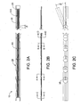
FIG. 2A is a top view of a touch fastener. -
FIG 2B is a side view of the touch fastener shown inFIG. 2A . -
FIG. 2C is a bottom view of the touch fastener shown inFIG. 2A . -
FIGS. 2D-2G are section views of the touch fastener shown inFIG. 2A at various locations along the touch fastener. -
FIG. 2H is a section view of a magnetically attractable material having a circular shape. -
FIG. 21 is a section view of a magnetically attractable material having an elliptical shape. -
FIG. 2J is a section view of a magnetically attractable material having a rectangular shape. -
FIG. 2K is a section view of a magnetically attractable material having a Y-shape. -
FIG. 2L is a section view of a magnetically attractable material having an X-shape. -
FIG. 2M is a section view of a magnetically attractable material having an I-shape. -
FIG. 3 is a sectional view of a touch fastener. -
FIG. 4 is a top view of an articulated joint of a touch fastener. -
FIG. 5 is a top view of a touch fastener being bent in a curved path. -
FIG. 6 is a top view of a touch fastener being bent in multiple curved paths. -
FIG. 7 is a top view of a touch fastener being bent at one articulated joint. -
FIG. 8 is a top view of a touch fastener being bent at two articulated joints. -
FIG. 9 is a top view of a touch fastener with one articulated joint. -
FIG. 10 is a top view of a touch fastener with several articulated joints spaced at different intervals. -
FIGS. 11-13 are top views of articulated joints of touch fasteners having different notch angles. -
FIG. 14 is a top view of a touch fastener with several articulated joints having one or more different notch angles. -
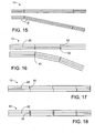
FIG. 15 is a top view of a touch fastener with two articulated joints. -
FIG. 16 is a top view of a touch fastener with one articulated joint having two different notch angles and another articulated joint having two equal notch angles. -
FIG. 17 is a top view of a touch fastener having a base defining slits. -
FIG. 18 is a top view of a touch fastener having a base defining slits extending across a majority of a lateral width of the base. -
FIG. 19 is a bottom view of a touch fastener including multiple discrete barrier segments extending across respective articulated joints. -
FIG. 20 is a bottom view of a touch fastener including discrete barrier segments secured to longitudinal center portions of adjoining base segments. -
FIG. 21 is a bottom view of a touch fastener including discrete barrier segments, each secured to a portion of one adjoining base segment. -
FIG. 22 is a bottom view of a touch fastener including discrete barrier segments, each secured to at least a portion of one adjoining base segment and longitudinal center portions of adjoining base segments. -
FIG. 23 is a schematic view of a touch fastener having a die cut base and barrier segments extending over at least one articulated joint. -
FIGS. 24-27 are top views of touch fasteners having barrier segments secured to a lower surface of a base, acting as a seal along the length of the base and having various notch configurations. -
FIG. 28 is a side view of a touch fastener having a flexible compressible gasket secured to a lower surface of a base. -
FIG. 29 is a bottom view of a touch fastener having a flexible compressible gasket secured to a lower surface of a base. -
FIG. 30 is a bottom view of a touch fastener having rotatable pivots at articulable joints. -
FIG. 31 is a bottom view of a touch fastener having base segments joined by a rotatable pivot at an articulable joint. -
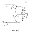
FIG. 32A is a schematic view of an apparatus and method of manufacturing a touch fastener. -
FIG. 32B is a section view of a mold roll having tool and spacer rings. -
FIG. 32C is a partial section view of a mold roll having cavities that receive molten resin. -
FIG. 33 is a cross-sectional view of a mold having a mold cavity for a seat and a touch fastener disposed in the mold cavity. -
FIGS. 34-35 are cross-sectional views a touch fasteners positioned in molds. -
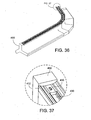
FIG. 36 is a partial perspective view of a mold with a pedestal configured to receive a touch fastener. -
FIG. 37 is a detail perspective view of an end of the pedestal shown inFIG. 36 . -
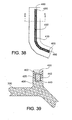
FIG. 38 is a top view of the mold with a pedestal shown inFIG. 36 . -
FIG. 39 is a section view of the mold with a pedestal shown inFIG. 38 . -
FIGS. 40-41 are cross-sectional views foam seat buns with touch fasteners. - Like reference symbols in the various drawings indicate like elements.
- Referring to
FIGS. 1A-1B , atouch fastener 10 includes anelongated base 20 havingmultiple segments 25 connected byarticulable joints 40, eachsegment 25 having upper and lower surfaces, 22 and 24 respectively. Thearticulable joints 40 facilitate bend points which allow the full length part to approximate a curve of thetouch fastener 10. A plurality oftouch fastener elements 100, as shown inFIG. 1 , extend from thelower surface 24 of thebase 20. Aflexible barrier 30 extends across at least one articulable joint 40 betweenadjacent base segments 25. In one implementation, thefastener 10 includes a magneticallyattractable material 60, such as steel wire, disposed along a center region of the upper surface of thebase 20 and extends across at least one articulable joint 40. In some cases, the magneticallyattractable material 60 is secured to theupper surface 22 of the base 20 byresin 65 or a discrete bead of hot melt adhesive or it may be attached mechanically by sandwiching it between thehook base 20 and a backing material orfilm 30 which are attached along the edges (e.g. byresin 29 or hot melt adhesive). In one example, a magneticallyattractable shim 60 is welded at the ends only. In other instances, awire 60 is glued in the middle of thepart 10 with a single dot of glue and thewire 60 is only held in place along the remaining length of theproduct 10 by the tent that is formed as the barrier film is laid over it and glued onto the hook. Significant issues may arise with continuous attachment of metal to plastic. They expand and contract at different rates due to the humidity and temperature of resin curing. If thewire 60 is glued in and not free to slide along the surface of expanding or contracting plastic, curved parts may result. - In some instances, the touch fastener product can be laminated to a mesh or scrim material. The scrim material can provide improved dimensional stability. Moreover, the scrim material can be magnetic (or attracted to magnets) (e.g., a ferrous-impregnated non-woven material), thus providing a magnetically attractable material as discussed above. Suitable examples of laminates are described in
U.S. Patent No. 5,518,795 to Kennedy et al. entitled LAMINATED HOOK FASTENER. - In the examples shown in
FIGS. 2A-2G , thetouch fastener 10 includes a magneticallyattractable material 60 having an iron composite strand construction. In one configuration, a magneticallyattractable material 60A includes amulti-filament thread 62 encapsulated with adry mixture 64 of a water based polymer emulsion and iron powder (e.g. having particles ranging in size from 50-200 µm). The outer surface 61 of the magneticallyattractable material 60 may be coated with anon-self adhering substance 66. - In another configuration, a magnetically
attractable material 60B includes an extruded longitudinal strand of plastic resin (e.g. Polypropylene or Polyetheylene) combined with iron powder (particles can range in size from 50-200 µm). Iron powder is compounded with a plastic resin such as polypropylene or polyethylene. The compounded resin is then converted into pellet form, which is fed to an extrusion process, where the pellets are melted and formed into any number of shapes.FIGS. 2H-2M provide cross sectional views of extruded shapes of the extruded magneticallyattractable material 60B. These shapes include circular, elliptical, rectangular, square, triangular, Y-shaped, X-shaped, and I-shaped. - Referring to
FIGS. 2A, 2B , and2F , in some implementations, the touch fastener includes an end barrier 70 (e.g. non-woven material) disposed at each longitudinal end of thebase 20. Theend barrier 70 aids prevention of resin entering onto thehooks 100 during the molding process. - In some implementations, a
touch fastener 10 includes anelongated base 20 having upper andlower surfaces touch fastener elements 100 extending from thelower surface 24 of thebase 20. Thebase 20 defines a series of spaced apart pairs ofopposite notches 50 in its longitudinal edges and forming respective articulable base joints 40. Adjacent pairs ofnotches 50 definerespective base segments 25 between them. Thenotches 50 are each sized with respect to an overall width of the base 20 such that, when one of thearticulable joints 40 is flexed to close one of itscorresponding notches 50, the other of itscorresponding notches 50 opens only to a longitudinal gap dimension less than about 0.5 millimeters. A gap of about 0.5 millimeter will generally not allow significant foam intrusion during a molding process such that it hinders hook performance. Nevertheless, larger gaps that do allow foam intrusion may still be employed because the amount of hook covered with foam would be small compared to the discontinued hook conventionally seen in foam pads that have short hook parts spaced apart to approximate a curve. - The
barrier 30 is generally wider than the base 20, such that thebarrier 30 generally extends beyond the longitudinal edges of thebase 20 and, in one implementation, extends beyond the longitudinal edges ofbase 20 atjoints 40, as shown inFIG 3 . In one example, thebarrier 30 comprises an elastomeric material and is more flexible than thebase 20. Thebarrier 30 may also be a film, such as a polyamide film having a nominal thickness of about 0.051 mm (0.002 inch). Although a polyamide film is described in one implementation, other films could also be used, including polyurethane or polyester or other resin films. Furthermore, thebarrier 30 may be bonded to the base 20 with adhesive or directly laminated to the resin of thehook base 20. - In one example, the
base 20 has a width of about 8 mm and is constructed from a resin, such as polyester, polypropylene, or nylon, and has a nominal thickness of about 0.254 mm (0.010 inch). The array offastener elements 100 extends over a longitudinal central region of alower face 24 of the base 20 that is about 4mm wide. In the same example, thefilm barrier 30 is about 12 mm wide, extending laterally and longitudinally beyond thebase 20. The selvedge that seals on the tool is comprised of the very flexible edges of thebarrier 30 and at the rigid selvedge of thebase 20. Thefastener elements 100 are hooks positioned in alternating rows of hooks facing in opposing directions. As shown inFIG. 3 , the rigid selvedge of thebase 20 and thebarrier 30 provide primary 21 and secondary 31 seals as thefastener part 10 is placed on atool 800 for a molding process. - The
film 30 mary be a polyamide film secured by a moisture cure polyurethane adhesive. Thefilm 30 has a nominal thickness of less than about 0.508 mm (0.020 inch). In one example, the film has a nominal thickness of about 0.051 mm (0.002 inch). In other examples the film has a nominal thickness of less than about 0.254 mm (0.010 inch). The film has a flexural rigidity of about 1800 mg-cm and a tensile stiffness of between about 1000 and about 3000 mg-cm. - Referring to
FIGS. 4-15 , thebase 20 defines a pair of first andsecond notches 50 in opposite longitudinal edges of the base 20 at an articulable joint 40. Thenotches 50 extend completely through thebase 20. Edges of the base 20 in first andsecond notches 50 may be bent in opposing directions to facilitate overlap during curvature of thebase 20.FIGS. 4-15 illustrate multiple implementations of approximate curvatures attainable withtouch fastener 10. - In the examples illustrated in
FIGS. 5-9 , the articulated joint provides a bend angle β of between about 20° and about 25°, preferably 22.5°. For manufacturability, thenotches 50 may be formed at standard intervals, as shown inFIGS. 5-8 , even though different portions of thefastener 10 are manipulated into curved profiles. In other examples, as shown inFIG. 9 , thenotches 50 may be formed only in regions where curvature of thefastener 10 is required. - Referring to
FIG. 10 , thearticulable joints 40 are spaced closer together along some regions of the base 20 than along other regions of thebase 20. In one example, thearticulable joints 40 have a longitudinal joint spacing of between about 5 and 50 millimeters. However, there could be some cases where thenotches 50 are required to have a longitudinal joint spacing of about 200 mm. In another example, thetouch fastener 10 includesarticulable joints 40 have a longitudinal joint spacing of about 200 to 400 millimeters with thenotches 50 that each define an included notch angle ϕ of about 12° between opposing surfaces of thebase 20. - In the examples illustrated in
FIGS. 11-13 , thenotches 50 define an included notch angle ϕ between opposing surfaces of thebase 20 of between about 2° and about 90°, preferably 20°.FIG. 14 illustrates an example of atouch fastener 10 having articulatedjoints 40 with definednotches 50 having different included notch angles ϕ1, ϕ2, such that the touch fastener attains greater bend angles β2 at articulatedjoints 40 with respective larger notch angles ϕ2.FIG. 15 illustrates an example of atouch fastener 10 having articulatedjoints 40 located only locations where bending is necessary (e.g. near the ends) and having definednotches 50 having the same included notch angles ϕ. - Referring to
FIGS. 16-18 showing embodiments which are not part of the invention, thebase 20 defines aslit 55 which extends through the base 20 from a longitudinal edge thereof at the articulable joint 40. In one example, as shown inFIG. 18 , theslit 55 extends across a majority of a lateral width of thebase 20.FIG. 16 illustrates another example where thebase 20 defines anotch 50 which extends from a longitudinal edge of the base 20 opposite theslit 55. Referring again toFIG. 1B , theflexible barrier 30 defines aslit 55 in through a longitudinal edge of thebarrier 30 and aligned with one of thenotches 50 at the articulable joint 40. In one example, thebarrier 30 defines twoslits 55 through opposite longitudinal edges of thebarrier 30 and aligned with first andsecond notches 50 of thebase 20. - Referring to
FIGS. 2C ,2G , and19-23 , thetouch fastener 10 may include multiple discrete barrier segments 35 (e.g. non-woven material), eachbarrier segment 35 extending across at least one respective articulable joint 40. In one example, thebarrier segment 35 may be secured tolongitudinal center portions 26 of twoadjoining base segments 25, as shown inFIG. 20 . In another example, thebarrier segment 35 is secured along aportion 27 of only one of the twoadjacent base segments 25 defining its respective articulable joint 40, as shown inFIG. 21 . The previous two examples may be combined, as shown inFIG. 22 , such that thebarrier segment 35 is secured to only one of the twoadjacent base segments 25 defining its respective articulable joint 40 as well as to longitudinal center portions of the twoadjoining base segments 25. Thebarrier segment 35 may be secured to theupper surface 22 of thebase 20 and/or thelower surface 24 of thebase 20. InFIG. 23 , thejoints 40 may be formed by rotary die cutting thebase 20. - Referring to
FIGS. 24-27 the embodiment ofFIG. 27 not being part of the invention, thetouch fastener 10 may includediscrete barrier segments 35 secured to the lower surface of thebase 20, eachbarrier segment 35 extending across at least one respective articulable joint 40. In another instance, thebarrier segment 35 does not extend across anyjoints 40, but rather acts as a seal over the length of thesegment 35. Thesebarrier segments 35 may comprise fabric patches or foam to stop foam intrusion during a molding process, such as molding a seat bun.FIGS. 24-27 illustrate multiple implementations ofnotch 50 configurations defined along the base 20 to achieve numerous curved configurations of thetouch fastener 10.FIG. 26 illustratesnotches 50 on opposite longitudinal edges of the base 20 at the articulable joint 40 with different notch angles ϕ defined between opposing base 20 surfaces.FIG. 27 illustratesnotches 50 defined at different locations on opposite longitudinal edges of thebase 20. In some implementations, thejoints 40 are formed in thebase 20, thebase 20 is bent at one ormore joints 40 to attain a desired curvature or shape, and thenbarrier segments 35 are secured over the joints 40 (e.g. bonding thebarrier segments 35 to bothadjacent base segments 25 defining each respective articulable joint 40) to hold the base 20 at the desired curvature or shape. The resultingtouch fastener 10 may then be placed on amolding tool 800 for subsequent use in a seat bun molding process. - Referring to
FIGS. 28-29 , thetouch fastener 10 may include a flexiblecompressible gasket 90 secured to the lower surface of thebase 20. Thegasket 90 extends across at least one articulable joint 40 to impede foam intrusion during a molding process. In another implementation, thebarrier 30 comprises a compressible gasket. - Referring to
FIGS. 30-31 showing embodiments which are not part of the invention,adjacent base segments 25 of thetouch fastener 10 are joined atrotatable pivots 120 at an articulable joints 40. InFIG. 30 ,adjacent base segments 25 are joined atarticulable joints 40 by alink 130 at rotatable pivots 120. In one example, thelink 130 attaches to basesegments 25 in a manner that minimizes or eliminates discontinuous hook. Another way to eliminate discontinuous hook at the joint 40 is shown inFIG. 31 , which depictsadjacent base segments 25 joined at the articulable joint 40 by arotatable pivot 120. - As described earlier, the
flexible barrier 30 may be extended across at least one articulable joint 40 betweenadjacent base segments 25. - A method of making a
touch fastener 10 with anexample apparatus 200, as illustrated inFIGS. 32A-32C , includes continuously introducing aflexible substrate 242 to agap 220 formed along a peripheral surface of arotating mold roll 230. Another step includes introducingmolten resin 210 to thegap 220 between thesubstrate 242 and the peripheral surface of themold roll 230, such that theresin 210 at least partially fills an array ofcavities 256 defined in therotating mold roll 230 to form resin stems 110 while abase 20 of resin interconnecting the stems 110 is laminated to the substrate on the peripheral surface of themold roll 230. Additional steps include formingengageable heads 120 on the stems and forming longitudinally spaced apart discontinuities 50, 55 in the base 20 to providearticulable joints 40 betweenadjacent base segments 25, across which thesubstrate 242 extends. In one implementation, thediscontinuities resin 210 to thegap 220 in longitudinally spaced apart quantities defining gaps between them. Additionally, thediscontinuities resin base 20 is stripped from themold roll 230. Theheads 120 may be formed by molding theheads 120 with thestems 110 in thecavities 256. Methods of forming molded touch fasteners having stems or fastener elements extending integrally therefrom are well known in the art. For example, a continuous extrusion/roll-forming method for molding fastener elements on an integral, sheet-form base is described in detail inU.S. Patent No. 4,794,028 and inU.S. Pat. No. 4,775,310 . During the step of formingarticulable joints 40, a pair of first andsecond notches 50 may be formed in opposite longitudinal edges of the base 20 at the articulable joint 40. Thenotches 50 may be formed by passing thebase 20 through a rotary or stationary die cutter. The notches 52 may extend completely through thebase 20. - In
example apparatus 200, thegap 220 is a nip defined between themold roll 230 and acounter-rotating pressure roll 232. Referring toFIG. 32B , themold roll 230 is assembled from multiple tool rings 234 and spacer rings 236 in a tooling region 238 and spacer rings in end regions 240 on either side of the tooling region. In this case, the spacer rings 236 in the end regions 240 are also used as vertical spacers that provide a mechanical limit helping control the height of thenip 220 and the amount of pressure applied to the resin and thus to a substrate, such as abarrier 30. Because themold roll 230 and thepressure roll 232 are in close proximity if not in actual contact, the spacer rings in the end regions 240 comprise an engineering elastomer, at least on their outer surfaces, to limit damage to therolls - Pressure applied in the nip causes the molten resin to enter
mold cavities 256, defined by the tool rings 234, which are configured to mold the molten resin into desired shapes (e.g. hooks with loop-engageable heads). For purposes of illustration, the size of the mold cavities is exaggerated and the number of mold cavities and associated tool and spacer rings is reduced in all of the Figures showing mold cavities. All of the mold rolls are assembled of tool and spacer rings although individual rings are only shown inFIG. 32B . - The
mold roll 230 is temperature controlled to solidify the molten resin as abase 20 and moldedhooks 100 extending from the base. Thehooks 100,resin base 20, and attachedsubstrate 30 are stripped from themold roll 230 by tension applied at a strippingroll 252. The resultingfastener product 10 may be gathered on a storage roll. - The method of making the
touch fastener 10 may also include forming aslit 55 that extends through the base 20 from a longitudinal edge thereof at an articulable joint 40. Theslits 55 may be formed by passingtouch fastener 10 through a rotary or stationary die cutter. Theslit 55 may extend across a majority of a lateral width of thebase 20. Another step may include forming anotch 50 that extends from a longitudinal edge of the base 20 opposite theslit 55. - In one example, the method of making
touch fastener 10 includes formingarticulable joints 40 closer together along some regions of the base 20 than along other regions of thebase 20. In one example, thearticulable joints 40 are formed with a longitudinal joint spacing of between about 5 and 50 millimeters. - The method of making
touch fastener 10 may also include securing aflexible barrier material 30 to thebase 20, such that thebarrier 30 extends across at least one articulable joint 40 betweenadjacent base segments 25. Additionally, aslit 55 may be formed in through a longitudinal edge of theflexible barrier 30 and aligned with one of thenotches 50 at the articulable joint 40. For example, two slits may be formed through opposite longitudinal edges of thebarrier 30 and aligned with first andsecond notches 50 of thebase 20. - In another implementation, the method of making the
touch fastener 10 may include securing multiplediscrete barrier segments 35 to thebase 20, where each barrier segment extends across at least one respective articulable joint 40. One step may include dispensing hot melt adhesive from a nozzle onto thebase 20, followed by dispensingbarrier segments 35 from a label dispenser onto and being secured tobase 20. Eachbarrier segment 35 may be secured to longitudinal center portions of twoadjoining base segments 25. In another example, eachbarrier segment 35 may be secured to only one of the twoadjacent base segments 25 defining its respective articulable joint 40. Furthermore, the step may include securing eachbarrier segment 35 to longitudinal center portions of twoadjoining base segments 25 as well as to only one of the twoadjacent base segments 25 defining its respective articulable joint 40. Another step may include disposing a fabric patch over at least one articulable joint. - The method of making
touch fastener 10 may also include the step of disposing a magneticallyattractable material 60, such as a steel wire, along a center region of an upper surface of thebase 20. The magneticallyattractable material 60 is positioned so as to extend across at least one of the articulable joints 40. In addition, the magneticallyattractable material 60 may be severed at the articulable joint 40 to allow greater movement about the joint 40. The magneticallyattractable material 60 can be secured to theupper surface 22 of the base 20 byresin 65. In another example, the magneticallyattractable material 60 is secured to theupper surface 22 of at least onebase segment 25 in at least one location along the base segment, allowing the magneticallyattractable material 60 to move at other locations. - Another step may include securing a flexible
compressible gasket 90 to a lower surface of thebase 20. Thegasket 90 may be positioned so as to extend across at least one articulable joint 40 to impede foam intrusion during a molding process. - In another implementation, the method of making the
touch fastener 10 may include the step of formingrotatable pivots 120 to joinadjacent base segments 25 at the articulable joints 40. In one example,adjacent base segments 25 are joined to alink 130 at rotatable pivots 120. - Referring to
FIG. 33 , a method of forming a seat foam bun includes providing amold cavity 310, defined by amold 300, having a shape corresponding to the shape of the seat foam bun, wherein themold cavity 310 defines atrench 330 in aflat mold surface 320. Another step includes providing atouch fastener 10 that includes anelongated base 20 havingmultiple segments 25 connected byarticulable joints 40, eachsegment 25 having upper and lower surfaces, 22 and 24 respectively, and a plurality oftouch fastener elements 100 extending from thelower surface 24 of thebase 20. Aflexible barrier 30 is extended across at least one articulable joint 40 betweenadjacent base segments 25. Additionally, thetouch fastener 10 is positioned along thetrench 330 with theflexible barrier 30 in contact with asurface 320 of themold cavity 310. Furthermore, a foamable resin is delivered into themold cavity 310 to form a seat foam bun. Theflexible barrier 30 resists intrusion of foamable resin into the plurality of thetouch fastener elements 100 at thejoints 40. - In some instances, as depicted in
FIG. 33 , amagnet 340 can be positioned in themold 300 to position thetouch fastener 10 in thetrench 330 of theflat mold surface 320. With thefastener 10 so positioned, a foamable liquid resin 505 is poured into themold cavity 310. An exothermic reaction occurs, causing the liquid resin to foam up to fill thecavity 310. The foam adheres or is otherwise secured to thefastener 10, which becomes a part of the surface of thefoam bun 500 removed from thecavity 310. -
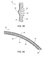
FIG. 34 depicts a cross-sectional view of atouch fastener 10A positioned in amold 300A. Amagnet 340A is positioned below thetrench 330A of themold 300A, where thetrench 330A has angledside portions 332. The force of magnetic attraction between themagnet 340A and the magneticallyattractable wire 60C holds thetouch fastener 10 in position against the surface of themold trench 330A during foaming. During the molding process, thebarrier 30A engages themold surface 320A in face-to-face contact to prevent fouling of thefastener elements 100. Contact pressure between thebarrier 30A and the mold wall is a function of the magnetic force applied to thewire 60C, and the bending stiffness of thebarrier 30A. -
FIG. 35 shows another example of atapered trench 330B, this one havingarcuate side walls 332B that extend upward from the bottom of thetrench 330B. Thefilm barrier 30B is of such a width that lateral edges of thefilm 30B are deflected upward as the central portion of afastener 10B is drawn against the bottom of thetrench 330B. The illustratedfastener 10B includes a thin strip of magneticallyattractable material 60D, instead of a wire, disposed within the central portion of the strip-form base 20B. The magneticallyattractable strip 60D may be in the form of a shim, strip, or iron powder glue strip encapsulated in the base 20 as it is formed. For example, an iron powder glue strip may be introduced into the nip of a continuous fastener molding apparatus during formation of a fastener. The magneticallyattractable strip 60D may also be snap fit or adhered to the base 20 after thebase 20 is formed. - In the examples illustrated in
FIGS. 36-39 , the mold 300 (e.g. cast aluminum) includes apedestal 400 that defines afastener trench 430 configured to receive thetouch fastener 10. In some implementations, thepedestal 400 defines amagnet trench 425 in a distal top portion that receives amagnet 440. Apedestal cap 402 is disposed over themagnet trench 425, enclosing themagnet 440 in themagnet trench 425. Themagnet 440 may be fixed in themagnet trench 425 with an adhesive 442 (e.g. epoxy). Thepedestal cap 402 defines thefastener trench 430. Once positioned in thefastener trench 430, the magneticallyattractable material 60 in the fastener is attracted by themagnet 440 and pulled down into thefastener trench 430. Anend magnet 450 is disposed in thefastener trench 430 and each longitudinal end of thetrench 430. Anend cap 460 closes off each end of thefastener trench 430. - The
touch fasteners 10 are molded into aseat foam bun 500, for example as depicted inFIGS. 40 and 41 . The moldedseat foam bun 500, depicted inFIG. 40 , includes a trench portion 44, which includes aplateau 510 havinglateral edges 520 andangled side walls 530. Atouch fastener 10C is molded into theplateau 510 and extends acrosslateral edges 520 and along a portion ofangled sides 530, such that thedistal edges 531 of the fastener 10c are disposed out of the plane of the fastener element array, and directed down into thebun 500. The touch fastener 10c includes a base 20 having anupper face 22 and alower face 24. Extending from thelower face 24 arefastener elements 100 having stems integrally molded thereto. A magneticallyattractable strip 60 is adhered to theupper face 22 of thebase 20 and afilm barrier 30 covers the magneticallyattractable strip 60 and expands beyond the lateral edges of thebase 20. Thebarrier 30 is molded into theseat foam bun 500, creating a smooth surface on thelateral edges 520 andangled side 530 walls of theplateau 510. - Other examples of forming a touch fastener for use as a mold insert are described in
U.S. Patent Application No. 10/791,204 to Line et al . entitled TOUCH FASTENER PRODUCTS;U.S. Provisional Patent Application No. 60/829761 to Janzen et al. entitled FASTENER SYSTEMS FOR SEAT CUSHIONS; andU.S. Provisional Patent Application No. 60/829,822 to Line et al. entitled TOUCH FASTENER PRODUCTS. - A number of implementations of the invention have been described. Nevertheless, it will be understood that various modifications may be made without departing from the scope of the invention as defined by the claims. For example, the
discrete barrier segments 35 are depicted inFIGS. 19-23 as circular. Nevertheless,discrete barrier segments 35 may also be square, hourglass, and other shapes. Accordingly, other implementations are within the scope of the following claims.
Claims (12)
- A touch fastener (10, 10A, 10B, 10C) comprising an elongated base (20) having an upper surface (22), a lower surface (24), and a plurality of touch fastener elements (100) extending from the lower surface (24) of the base (20), wherein the base (20) defines a series of spaced apart pairs of opposite notches (50) in its longitudinal edges and forming respective articulable base joints (40), adjacent pairs of notches (50) defining respective base segments (25) therebetween;
characterized in that the notches (50) are each sized with respect to an overall width of the base (20) such that, when one of the articulable joints (40) is flexed to close one of its corresponding notches (50), the other of its corresponding notches (50) opens only to a longitudinal gap dimension less than about 0.5 millimeter. - The touch fastener (10, 10A, 10B, 10C) of anyone of the preceding claims, wherein the notches (50) each define an included notch angle (ϕ) of between about 2 and 90 degrees between opposing base surfaces.
- The touch fastener (10, 10A, 10B, 10C) of anyone of the preceding claims, wherein the base edges in the first and second notches (50) are bent in opposing directions.
- The touch fastener (10, 10A, 10B, 10C) of claim 1, wherein the articulable joints (40) are spaced closer together along some regions of the base (20) than along other regions of the base (20), preferably having a longitudinal joint spacing of between about 5 and 50 millimeters.
- The touch fastener (10, 10A, 10B, 10C) of anyone of the preceding claims, further comprising at least one magnetically attractable material (60, 60A, 60B, 60C, 60D) disposed along a center region of the upper surface (22) of the base (20), preferably having a width less than about 25% of the width of the base (20), and particularly wherein the magnetically attractable material (60, 60A, 60B, 60C, 60D) extends across at least one of the articulable joints (40).
- The touch fastener (10, 10A, 10B, 10C) of claim 5, wherein the magnetically attractive material (60, 60A, 60B, 60C, 60D) comprises a plurality of iron particles that are fused together to form a cylindrical shape.
- The touch fastener (10, 10A, 10B, 10C) of anyone of claims 5-6, wherein the magnetically attractable material (60, 60A, 60B, 60C, 60D) is secured to the upper surface (22) of at least one base segment (25) in at least one location along the base segment (25), allowing the magnetically attractable material (60, 60A, 60B, 60C, 60D) to move at other locations.
- The touch fastener (10, 10A, 10B, 10C) of any of the preceding claims, further comprising a flexible barrier (30) extending across at least one articulable joint (40) between adjacent base segments (25).
- The touch fastener (10, 10A, 10B, 10C) of any of the preceding claims, wherein the barrier (30, 35) is wider than the base (20), such that the barrier (30, 35) extends beyond longitudinal edges of the base (20), particularly wherein the barrier (30, 35) extends beyond longitudinal edges of the base (20) at the joints (40).
- The touch fastener (10, 10A, 10B, 10C) of claim 9, wherein the barrier (30, 35) defines a slit (55) through a longitudinal edge of the flexible barrier (30, 35) and aligned with the articulable joint (40).
- The touch fastener (10, 10A, 10B, 10C) of anyone of the preceding claims, further comprising multiple discrete barrier segments (35), each barrier segment (35) extending across at least one respective articulable joint (40), wherein each barrier segment (35) is secured to longitudinal center portions (26) of two adjoining base segments (25) or only one of the two adjacent base segments (25) defining its respective articulable joint (40).
- The touch fastener (10, 10A, 10B, 10C) of anyone of the preceding claims, further comprising a flexible compressible gasket (90) secured to the lower surface (24) of the base (20) and preferably extending across at least one articulable joint (40) to impede foam intrusion during a molding process.
Applications Claiming Priority (3)
| Application Number | Priority Date | Filing Date | Title |
|---|---|---|---|
| US82983606P | 2006-10-17 | 2006-10-17 | |
| US82999606P | 2006-10-18 | 2006-10-18 | |
| PCT/US2007/081612 WO2008048992A2 (en) | 2006-10-17 | 2007-10-17 | Touch fastener products |
Publications (2)
| Publication Number | Publication Date |
|---|---|
| EP2073658A2 EP2073658A2 (en) | 2009-07-01 |
| EP2073658B1 true EP2073658B1 (en) | 2015-08-26 |
Family
ID=39314806
Family Applications (1)
| Application Number | Title | Priority Date | Filing Date |
|---|---|---|---|
| EP07863414.4A Not-in-force EP2073658B1 (en) | 2006-10-17 | 2007-10-17 | Touch fastener products |
Country Status (3)
| Country | Link |
|---|---|
| US (2) | US7971325B2 (en) |
| EP (1) | EP2073658B1 (en) |
| WO (1) | WO2008048992A2 (en) |
Families Citing this family (16)
| Publication number | Priority date | Publication date | Assignee | Title |
|---|---|---|---|---|
| US20090276986A1 (en) * | 2008-05-12 | 2009-11-12 | Velcro Industries B.V. | Touch fastener products |
| US20090300890A1 (en) * | 2008-06-05 | 2009-12-10 | Ykk Corporation Of America | Flexible fastener strip assembly and methods of assembling the same |
| TWI370726B (en) * | 2008-10-21 | 2012-08-21 | Taiwan Paiho Ltd | Fastening strap and manufacturing method thereof |
| TWI403282B (en) * | 2008-12-05 | 2013-08-01 | Taiwan Paiho Ltd | Fastening assembly and cushion having fastening assembly |
| TW201023783A (en) * | 2008-12-26 | 2010-07-01 | Taiwan Paiho Ltd | Fastening assembly and cushion having fastening assembly |
| US20120260401A1 (en) * | 2011-04-12 | 2012-10-18 | Darryl Moskowitz | Releasable securement device |
| DE102011104886A1 (en) | 2011-06-18 | 2012-12-20 | Gottlieb Binder Gmbh & Co. Kg | fastening system |
| EP3050746B1 (en) * | 2011-12-13 | 2017-10-18 | Velcro Bvba | Mold-in touch fastening product |
| US9315134B2 (en) | 2013-11-08 | 2016-04-19 | Velcro BVBA | Securing seat trim covers to foam cushions |
| US9873363B2 (en) | 2015-04-27 | 2018-01-23 | Velcro BVBA | Securing seat trim covers to foam cushions |
| US10548374B2 (en) | 2015-07-17 | 2020-02-04 | Ykk Corporation | Fastening tape with flexibility in the longitudinal direction and associated methods |
| US10189387B2 (en) | 2015-07-17 | 2019-01-29 | Ykk Corporation | Fastening tape with flexibility in the lateral direction and associated methods |
| DE102018002180A1 (en) * | 2018-03-17 | 2019-09-19 | Gottlieb Binder Gmbh & Co. Kg | Fastener part |
| KR102063224B1 (en) * | 2018-04-11 | 2020-01-07 | 송위현 | Curved Fastener Tape its manufacturing method |
| KR102684712B1 (en) * | 2019-08-31 | 2024-07-11 | 박우덕 | Method for fabricating of angular velcro tapes |
| CN118144279B (en) * | 2024-05-09 | 2024-07-23 | 浙江大学 | Method and system for automatically designing contact type quick fastening structure based on 3D printing |
Family Cites Families (10)
| Publication number | Priority date | Publication date | Assignee | Title |
|---|---|---|---|---|
| US3717908A (en) * | 1971-03-31 | 1973-02-27 | American Velcro Inc | Deformable fastening device |
| US5147430A (en) * | 1987-10-01 | 1992-09-15 | Kidd Steven A | Air scoop screen |
| KR940006314B1 (en) * | 1987-12-15 | 1994-07-16 | 가부시끼가이샤 구라레 | Fastener component |
| US5180618A (en) * | 1990-01-25 | 1993-01-19 | Velcro Industries B.V. | Separable fasteners for attachment to other objects |
| US5260015A (en) * | 1991-08-16 | 1993-11-09 | Velcro Industries, B.V. | Method for making a laminated hook fastener |
| JP2788564B2 (en) * | 1992-02-10 | 1998-08-20 | ワイケイケイ株式会社 | Hook-and-loop fastener assembly for seat cushion |
| US6460230B2 (en) * | 2000-01-12 | 2002-10-08 | Kuraray Co., Ltd. | Mold-in fastening member and production of molded resin article having mold-in fastening member |
| US6656563B1 (en) | 2000-05-23 | 2003-12-02 | Velcro Industries B.V. | Segmented separable fastener |
| JP2004000321A (en) * | 2002-03-26 | 2004-01-08 | Kuraray Co Ltd | Locking member for mold-in molding and method for producing resin molded body |
| US7425360B2 (en) | 2004-03-02 | 2008-09-16 | Velcro Industries B.V. | Touch fastener products |
-
2007
- 2007-10-17 WO PCT/US2007/081612 patent/WO2008048992A2/en not_active Ceased
- 2007-10-17 US US11/873,664 patent/US7971325B2/en active Active
- 2007-10-17 EP EP07863414.4A patent/EP2073658B1/en not_active Not-in-force
-
2011
- 2011-07-01 US US13/175,644 patent/US8658068B2/en not_active Expired - Fee Related
Also Published As
| Publication number | Publication date |
|---|---|
| US7971325B2 (en) | 2011-07-05 |
| US20110260360A1 (en) | 2011-10-27 |
| WO2008048992A2 (en) | 2008-04-24 |
| WO2008048992A3 (en) | 2008-11-13 |
| US8658068B2 (en) | 2014-02-25 |
| US20080092348A1 (en) | 2008-04-24 |
| EP2073658A2 (en) | 2009-07-01 |
Similar Documents
| Publication | Publication Date | Title |
|---|---|---|
| US7971325B2 (en) | Touch fastener products | |
| KR101862431B1 (en) | Touch fastening product face configuration | |
| US9445650B2 (en) | Male surface fastener member for use in a cushion body mold and manufacturing method thereof | |
| EP4143446B1 (en) | Mold-in fasteners | |
| EP3050746B1 (en) | Mold-in touch fastening product | |
| CA2954712C (en) | Dimensionally flexible touch fastener strip | |
| US7488527B2 (en) | Molded touch fasteners | |
| JP6246324B2 (en) | Molded surface fastener | |
| US20040094860A2 (en) | Continuous molding of fastener products with a mold belt | |
| GB2468869A (en) | Fastener strip for use with cushion body | |
| US20170055644A1 (en) | Releasable fastenings with barriers | |
| JP2003529500A (en) | Seal closure | |
| CN117715559B (en) | In-mold fastener product |
Legal Events
| Date | Code | Title | Description |
|---|---|---|---|
| PUAI | Public reference made under article 153(3) epc to a published international application that has entered the european phase |
Free format text: ORIGINAL CODE: 0009012 |
|
| 17P | Request for examination filed |
Effective date: 20090427 |
|
| AK | Designated contracting states |
Kind code of ref document: A2 Designated state(s): AT BE BG CH CY CZ DE DK EE ES FI FR GB GR HU IE IS IT LI LT LU LV MC MT NL PL PT RO SE SI SK TR |
|
| RIN1 | Information on inventor provided before grant (corrected) |
Inventor name: KRAUS, DAVID P., JR. Inventor name: FERRY, KRISTEL Inventor name: CINA, MICHAEL Inventor name: JANZEN, DANIEL LEE Inventor name: PUBRAT, DAVID Inventor name: LINE, KEVIN KEITH Inventor name: GIRARD, STEPHANIE XAVIER Inventor name: CLARNER, MARK A. |
|
| RIN1 | Information on inventor provided before grant (corrected) |
Inventor name: CLARNER, MARK A. Inventor name: KRAUS, DAVID P., JR. Inventor name: FERRY, KRISTEL Inventor name: LINE, KEVIN KEITH Inventor name: CINA, MICHAEL Inventor name: JANZEN, DANIEL LEE Inventor name: GIRARD, STEPHANIE XAVIER Inventor name: PUBRAT, DAVID |
|
| DAX | Request for extension of the european patent (deleted) | ||
| 17Q | First examination report despatched |
Effective date: 20130109 |
|
| GRAP | Despatch of communication of intention to grant a patent |
Free format text: ORIGINAL CODE: EPIDOSNIGR1 |
|
| INTG | Intention to grant announced |
Effective date: 20150325 |
|
| GRAS | Grant fee paid |
Free format text: ORIGINAL CODE: EPIDOSNIGR3 |
|
| GRAA | (expected) grant |
Free format text: ORIGINAL CODE: 0009210 |
|
| AK | Designated contracting states |
Kind code of ref document: B1 Designated state(s): AT BE BG CH CY CZ DE DK EE ES FI FR GB GR HU IE IS IT LI LT LU LV MC MT NL PL PT RO SE SI SK TR |
|
| REG | Reference to a national code |
Ref country code: GB Ref legal event code: FG4D |
|
| REG | Reference to a national code |
Ref country code: CH Ref legal event code: EP |
|
| REG | Reference to a national code |
Ref country code: AT Ref legal event code: REF Ref document number: 744606 Country of ref document: AT Kind code of ref document: T Effective date: 20150915 |
|
| REG | Reference to a national code |
Ref country code: IE Ref legal event code: FG4D |
|
| REG | Reference to a national code |
Ref country code: DE Ref legal event code: R096 Ref document number: 602007042839 Country of ref document: DE |
|
| REG | Reference to a national code |
Ref country code: AT Ref legal event code: MK05 Ref document number: 744606 Country of ref document: AT Kind code of ref document: T Effective date: 20150826 |
|
| REG | Reference to a national code |
Ref country code: LT Ref legal event code: MG4D |
|
| PG25 | Lapsed in a contracting state [announced via postgrant information from national office to epo] |
Ref country code: LV Free format text: LAPSE BECAUSE OF FAILURE TO SUBMIT A TRANSLATION OF THE DESCRIPTION OR TO PAY THE FEE WITHIN THE PRESCRIBED TIME-LIMIT Effective date: 20150826 Ref country code: FI Free format text: LAPSE BECAUSE OF FAILURE TO SUBMIT A TRANSLATION OF THE DESCRIPTION OR TO PAY THE FEE WITHIN THE PRESCRIBED TIME-LIMIT Effective date: 20150826 Ref country code: GR Free format text: LAPSE BECAUSE OF FAILURE TO SUBMIT A TRANSLATION OF THE DESCRIPTION OR TO PAY THE FEE WITHIN THE PRESCRIBED TIME-LIMIT Effective date: 20151127 Ref country code: LT Free format text: LAPSE BECAUSE OF FAILURE TO SUBMIT A TRANSLATION OF THE DESCRIPTION OR TO PAY THE FEE WITHIN THE PRESCRIBED TIME-LIMIT Effective date: 20150826 |
|
| REG | Reference to a national code |
Ref country code: NL Ref legal event code: MP Effective date: 20150826 |
|
| PG25 | Lapsed in a contracting state [announced via postgrant information from national office to epo] |
Ref country code: SE Free format text: LAPSE BECAUSE OF FAILURE TO SUBMIT A TRANSLATION OF THE DESCRIPTION OR TO PAY THE FEE WITHIN THE PRESCRIBED TIME-LIMIT Effective date: 20150826 Ref country code: PT Free format text: LAPSE BECAUSE OF FAILURE TO SUBMIT A TRANSLATION OF THE DESCRIPTION OR TO PAY THE FEE WITHIN THE PRESCRIBED TIME-LIMIT Effective date: 20151228 Ref country code: IS Free format text: LAPSE BECAUSE OF FAILURE TO SUBMIT A TRANSLATION OF THE DESCRIPTION OR TO PAY THE FEE WITHIN THE PRESCRIBED TIME-LIMIT Effective date: 20151226 Ref country code: ES Free format text: LAPSE BECAUSE OF FAILURE TO SUBMIT A TRANSLATION OF THE DESCRIPTION OR TO PAY THE FEE WITHIN THE PRESCRIBED TIME-LIMIT Effective date: 20150826 Ref country code: PL Free format text: LAPSE BECAUSE OF FAILURE TO SUBMIT A TRANSLATION OF THE DESCRIPTION OR TO PAY THE FEE WITHIN THE PRESCRIBED TIME-LIMIT Effective date: 20150826 Ref country code: AT Free format text: LAPSE BECAUSE OF FAILURE TO SUBMIT A TRANSLATION OF THE DESCRIPTION OR TO PAY THE FEE WITHIN THE PRESCRIBED TIME-LIMIT Effective date: 20150826 |
|
| PG25 | Lapsed in a contracting state [announced via postgrant information from national office to epo] |
Ref country code: NL Free format text: LAPSE BECAUSE OF FAILURE TO SUBMIT A TRANSLATION OF THE DESCRIPTION OR TO PAY THE FEE WITHIN THE PRESCRIBED TIME-LIMIT Effective date: 20150826 |
|
| PG25 | Lapsed in a contracting state [announced via postgrant information from national office to epo] |
Ref country code: SK Free format text: LAPSE BECAUSE OF FAILURE TO SUBMIT A TRANSLATION OF THE DESCRIPTION OR TO PAY THE FEE WITHIN THE PRESCRIBED TIME-LIMIT Effective date: 20150826 Ref country code: CZ Free format text: LAPSE BECAUSE OF FAILURE TO SUBMIT A TRANSLATION OF THE DESCRIPTION OR TO PAY THE FEE WITHIN THE PRESCRIBED TIME-LIMIT Effective date: 20150826 Ref country code: EE Free format text: LAPSE BECAUSE OF FAILURE TO SUBMIT A TRANSLATION OF THE DESCRIPTION OR TO PAY THE FEE WITHIN THE PRESCRIBED TIME-LIMIT Effective date: 20150826 Ref country code: IT Free format text: LAPSE BECAUSE OF FAILURE TO SUBMIT A TRANSLATION OF THE DESCRIPTION OR TO PAY THE FEE WITHIN THE PRESCRIBED TIME-LIMIT Effective date: 20150826 Ref country code: DK Free format text: LAPSE BECAUSE OF FAILURE TO SUBMIT A TRANSLATION OF THE DESCRIPTION OR TO PAY THE FEE WITHIN THE PRESCRIBED TIME-LIMIT Effective date: 20150826 |
|
| REG | Reference to a national code |
Ref country code: DE Ref legal event code: R097 Ref document number: 602007042839 Country of ref document: DE |
|
| PG25 | Lapsed in a contracting state [announced via postgrant information from national office to epo] |
Ref country code: LU Free format text: LAPSE BECAUSE OF FAILURE TO SUBMIT A TRANSLATION OF THE DESCRIPTION OR TO PAY THE FEE WITHIN THE PRESCRIBED TIME-LIMIT Effective date: 20151017 Ref country code: RO Free format text: LAPSE BECAUSE OF FAILURE TO SUBMIT A TRANSLATION OF THE DESCRIPTION OR TO PAY THE FEE WITHIN THE PRESCRIBED TIME-LIMIT Effective date: 20150826 |
|
| REG | Reference to a national code |
Ref country code: CH Ref legal event code: PL |
|
| RAP2 | Party data changed (patent owner data changed or rights of a patent transferred) |
Owner name: VELCRO BVBA |
|
| PG25 | Lapsed in a contracting state [announced via postgrant information from national office to epo] |
Ref country code: MC Free format text: LAPSE BECAUSE OF FAILURE TO SUBMIT A TRANSLATION OF THE DESCRIPTION OR TO PAY THE FEE WITHIN THE PRESCRIBED TIME-LIMIT Effective date: 20150826 |
|
| PLBE | No opposition filed within time limit |
Free format text: ORIGINAL CODE: 0009261 |
|
| STAA | Information on the status of an ep patent application or granted ep patent |
Free format text: STATUS: NO OPPOSITION FILED WITHIN TIME LIMIT |
|
| REG | Reference to a national code |
Ref country code: DE Ref legal event code: R082 Ref document number: 602007042839 Country of ref document: DE Representative=s name: FISH & RICHARDSON P.C., DE Ref country code: DE Ref legal event code: R081 Ref document number: 602007042839 Country of ref document: DE Owner name: VELCRO BVBA, BE Free format text: FORMER OWNER: VELCRO INDUSTRIES B.V. (NL), CURACAO, AN |
|
| GBPC | Gb: european patent ceased through non-payment of renewal fee |
Effective date: 20151126 |
|
| REG | Reference to a national code |
Ref country code: IE Ref legal event code: MM4A |
|
| PG25 | Lapsed in a contracting state [announced via postgrant information from national office to epo] |
Ref country code: LI Free format text: LAPSE BECAUSE OF NON-PAYMENT OF DUE FEES Effective date: 20151031 Ref country code: CH Free format text: LAPSE BECAUSE OF NON-PAYMENT OF DUE FEES Effective date: 20151031 |
|
| REG | Reference to a national code |
Ref country code: FR Ref legal event code: ST Effective date: 20160630 |
|
| 26N | No opposition filed |
Effective date: 20160530 |
|
| PG25 | Lapsed in a contracting state [announced via postgrant information from national office to epo] |
Ref country code: SI Free format text: LAPSE BECAUSE OF FAILURE TO SUBMIT A TRANSLATION OF THE DESCRIPTION OR TO PAY THE FEE WITHIN THE PRESCRIBED TIME-LIMIT Effective date: 20150826 Ref country code: FR Free format text: LAPSE BECAUSE OF NON-PAYMENT OF DUE FEES Effective date: 20151102 |
|
| PG25 | Lapsed in a contracting state [announced via postgrant information from national office to epo] |
Ref country code: IE Free format text: LAPSE BECAUSE OF NON-PAYMENT OF DUE FEES Effective date: 20151017 Ref country code: GB Free format text: LAPSE BECAUSE OF NON-PAYMENT OF DUE FEES Effective date: 20151126 |
|
| PG25 | Lapsed in a contracting state [announced via postgrant information from national office to epo] |
Ref country code: BE Free format text: LAPSE BECAUSE OF FAILURE TO SUBMIT A TRANSLATION OF THE DESCRIPTION OR TO PAY THE FEE WITHIN THE PRESCRIBED TIME-LIMIT Effective date: 20150826 |
|
| PG25 | Lapsed in a contracting state [announced via postgrant information from national office to epo] |
Ref country code: BG Free format text: LAPSE BECAUSE OF FAILURE TO SUBMIT A TRANSLATION OF THE DESCRIPTION OR TO PAY THE FEE WITHIN THE PRESCRIBED TIME-LIMIT Effective date: 20150826 Ref country code: HU Free format text: LAPSE BECAUSE OF FAILURE TO SUBMIT A TRANSLATION OF THE DESCRIPTION OR TO PAY THE FEE WITHIN THE PRESCRIBED TIME-LIMIT; INVALID AB INITIO Effective date: 20071017 |
|
| PG25 | Lapsed in a contracting state [announced via postgrant information from national office to epo] |
Ref country code: CY Free format text: LAPSE BECAUSE OF FAILURE TO SUBMIT A TRANSLATION OF THE DESCRIPTION OR TO PAY THE FEE WITHIN THE PRESCRIBED TIME-LIMIT Effective date: 20150826 |
|
| PG25 | Lapsed in a contracting state [announced via postgrant information from national office to epo] |
Ref country code: TR Free format text: LAPSE BECAUSE OF FAILURE TO SUBMIT A TRANSLATION OF THE DESCRIPTION OR TO PAY THE FEE WITHIN THE PRESCRIBED TIME-LIMIT Effective date: 20150826 Ref country code: MT Free format text: LAPSE BECAUSE OF FAILURE TO SUBMIT A TRANSLATION OF THE DESCRIPTION OR TO PAY THE FEE WITHIN THE PRESCRIBED TIME-LIMIT Effective date: 20150826 |
|
| PGFP | Annual fee paid to national office [announced via postgrant information from national office to epo] |
Ref country code: DE Payment date: 20181029 Year of fee payment: 12 |
|
| REG | Reference to a national code |
Ref country code: DE Ref legal event code: R119 Ref document number: 602007042839 Country of ref document: DE |
|
| PG25 | Lapsed in a contracting state [announced via postgrant information from national office to epo] |
Ref country code: DE Free format text: LAPSE BECAUSE OF NON-PAYMENT OF DUE FEES Effective date: 20200501 |