EP2073326A1 - High voltage switch - Google Patents
High voltage switch Download PDFInfo
- Publication number
- EP2073326A1 EP2073326A1 EP07255037A EP07255037A EP2073326A1 EP 2073326 A1 EP2073326 A1 EP 2073326A1 EP 07255037 A EP07255037 A EP 07255037A EP 07255037 A EP07255037 A EP 07255037A EP 2073326 A1 EP2073326 A1 EP 2073326A1
- Authority
- EP
- European Patent Office
- Prior art keywords
- electrodes
- switch
- switch according
- electrode
- raised
- Prior art date
- Legal status (The legal status is an assumption and is not a legal conclusion. Google has not performed a legal analysis and makes no representation as to the accuracy of the status listed.)
- Ceased
Links
Images


Classifications
-
- H—ELECTRICITY
- H01—ELECTRIC ELEMENTS
- H01T—SPARK GAPS; OVERVOLTAGE ARRESTERS USING SPARK GAPS; SPARKING PLUGS; CORONA DEVICES; GENERATING IONS TO BE INTRODUCED INTO NON-ENCLOSED GASES
- H01T1/00—Details of spark gaps
- H01T1/20—Means for starting arc or facilitating ignition of spark gap
- H01T1/22—Means for starting arc or facilitating ignition of spark gap by the shape or the composition of the electrodes
Definitions
- This invention relates to a high voltage switch, in particular to a high pressure gas switch for use in high voltage, high power switching applications.
- High pressure gas switches are widely used in high pulse power switching. They offer a very simple compact means of very high pulse power switching with low mass and volume. However, known designs for such switches have a relatively limited life due to uneven and damaging electrode wear.
- a switch according to preferred embodiments of the present invention has been found to have a long operational life, despite the high voltages being switched, of the order of several hundred kilovolts and instantaneous power levels of the order of Gigawatts.
- Long operational life is characterised in this invention by even wearing of the facing surfaces of the electrodes, so preserving the operational characteristics of the switch, with no significant localised damage such as pitting or fracturing.
- the switch has been found to be less sensitive to temperature variations that may otherwise cause prior art switches to operate at reduced power levels outside optimal temperature ranges.
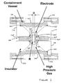
- a simple high pressure gas switch according to a preferred embodiment of the present invention will now be described with reference to Figure 1 .
- the switch may be used in a number of different applications, preferably those requiring the switching of voltages of the order of several hundred kilovolts at high instantaneous power levels, but at relatively low overall energy levels. Such applications are in contrast to switching in X-ray apparatus, for example, in which voltages of the order of megavolts or higher need to be switched, with high overall energy levels.
- the switch 100 comprises a high pressure containment vessel 105, preferably made from a high strength metal such as stainless steel and in the shape of a cylinder.
- Insulating members 110 preferably made from ceramic or a plastic such as nylon or polypropylene, serve both as the end walls of the high pressure containment vessel and to electrically isolate the respective electrode 115, 120 from the cylindrical brass portion 105 of the vessel.
- Sealing rings 125 are provided to seal the vessel when in its assembled state with the insulating members 110 held securely in place by a number of bolts 130.
- the containment vessel provides a void 135 around the electrodes for holding a suitable gas, preferably nitrogen, hydrogen or SF 6 , under very high pressure, preferably in the range of 300psi to 1200psi.
- the electrodes 115, 120 are held in a fixed position by the insulating members 110 so that there is a nominal gap D between the electrodes 115, 120. Electrical connection to each of the electrodes 115, 120 is by means of an access hole 140 created in the respective insulating member 110 to expose a connecting portion 145 of the respective electrode 115, 120. Electrical connection to the electrodes 115, 120 is by any of a number of possible configurations, for example by means of a push-fit sleeve that may fit tightly around a slightly narrowed portion of the connecting portion 145 to ensure a reliable electrical connection. However, preferably, any such electrical connections may be additionally soldered or otherwise bonded for extra reliability appropriate to the voltage levels intended for this switch 100.
- a sectional view is provide through an electrode 200 of a first preferred design, with dimensions shown in millimetres.
- the electrode 200 is made preferably of brass and comprises a facing surface 205 having a flat central region 210 surrounded by a raised annular region 215.
- the radius of curvature of any rounded surface of the raised annular region 215 is relatively small in comparison with the intended width of the electrode 200 so that the raised surface features on the facing surface 205 serve to increase the surface area of the electrode over which erosion takes place.
- the radius of curvature of the raised surface features is made significantly less than the intended electrode separation so that the area over which field enhancement and hence enhanced erosion takes place is increased.
- the raised features 215 according to these preferred design considerations has been found to contribute to the extended operational life of the switch 100 according to preferred embodiments of the present invention.
- this first preferred design may be used for both of the electrodes 115, 120, substantially as shown in the example of Figure 1 , the advantages of long operation life for a switch employing this first design of electrode 200 has been found to be preserved even though one of the electrodes is provided with an entirely flat facing surface 205.
- the initially flat facing surface has been found to have a shallow annular depression formed corresponding to the shape and position of the raised annular portion 215 of the opposite electrode. This has the effect of preserving or, in the case of an initially flat electrode, enhancing the degree of similarity in the profiles of the facing surfaces of the electrodes so as to maintain a substantially even gap between the electrodes and hence to maintain substantially even wear over their facing surfaces.
- a second preferred design for a negative, or high voltage (HV) electrode 300 is shown as a sectional view with dimensions indicated in millimetres.
- the facing surface 305 of the electrode is provided with an outer raised annular region 310 and a concentrically arranged inner raised annular region 315, with flat regions in between to give a "corrugated" facing surface 305 to the electrode 300.
- the preferred design for a corresponding positive, or ground electrode 350 is shown in sectional view in Figure 3b to have a simple plane facing surface 355.
- first and second preferred electrode designs described above use continuous raised annular portions
- an arrangement of discrete "mounds" may be provided across the facing surface of the HV electrode, rather than using one or more annuli.
- Each mound may have a similar radius of curvature to that of the annular portions in the first and second designs.
- an arrangement of discrete mounds may provide a greater facing surface area for an electrode than that provided using continuous annuli and this feature is likely to contribute to extended electrode life.
- a switch 100 using electrodes of the preferred designs described above, is operated by applying a voltage across the electrodes 115, 120 which increases the electric field within the high pressure gas until breakdown occurs.
- the discharge following breakdown is a narrow plasma channel across the gap between the electrodes 115, 120. It has been observed that the breakdown channel predominantly occurs at points over the raised surface of an annulus or a discrete mound on the facing surface where the electric field strength is enhanced.
- the observed evenness of electrode wear over the raised surface features in particular, despite use of an initially flat-faced opposing electrode suggests that breakdown occurs randomly at any point over the raise surface, not just that region at the apex of the raised surface for which the initial gap between electrodes is a minimum.
- the radius of the raised annular region 215 of the high voltage electrode 200 was reduced by 0.26mm from nominal and the flat central region 210 was eroded 0.4mm from nominal.
- the flat-faced ground electrode was also eroded and an annular depression, 0.2mm deep, of substantially the same sectional profile as the raised annular region of the high voltage electrode, was worn in its flat facing surface.
- the plasma channel diameter is small and its inductance is significant, thereby limiting the rate of rise of current through the switch 100.
- the electrical breakdown strength of the gas contained in the switch 100 increases almost linearly with pressure.
- high gas pressure is used so that the required gap between the electrodes and hence the plasma channel length is substantially minimised.
- a reduced plasma channel length enables faster current rise and hence reduced switching time.
- the gas contained in the switch 100 is at a pressure of between 300psi and 1200psi.
- a further advantageous feature of a switch 100 according to preferred embodiments of the present invention described above is an observed reduced temperature dependence when the switch is used in a pulsed charge application.
- the breakdown voltage between electrodes of the switch is a function not only of gas pressure but also of gas temperature.
- a very high gas pressure is used, preferably in excess of 500psi, if the gas switch 100 is charged in the first microsecond to a very high field strength, the breakdown voltage of the switch has been observed to become predominantly a function of the plasma channel formation time, rather than of gas temperature and pressure. This property is exploited in such applications to reduce the switch dependence on gas pressure/ temperature, so increasing the temperature range over which the switch 100 operates at the required power levels.
- the electric field across the gap between the raised annular regions of the electrodes 115, 120 can be estimated by considering the electric field between two conducting cylinders 400, 405 of radius R and separation D.
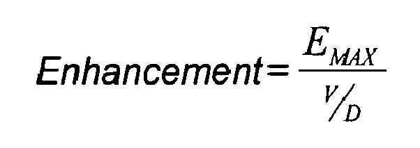
- the electric field would be simply V/D (volts/metre).
- a plot 500 of the enhanced E-Field is shown in Figure 5 . As can be seen from the plot 500 in Figure 5 , where R ⁇ D the maximum electric field tends to become independent of the gap separation D.
- FIG. 7 A similar plot of the enhanced field due to the radius of the annular gap is shown in Figure 7 .
- the plot 700 for the "single-ended" switch arrangement of Figure 6 is provided along with the plot 500 for the "double-ended" switch arrangement from Figure 4 and Figure 5 , for comparison.
- a greater enhancement is achieved with the single-ended switch arrangement, which advantageously is also simpler and cheaper to produce.
- the analysis supports the observation referred to above that the use of one flat-faced electrode and one "radiused" electrode in preferred embodiments of the switch 100 provides for increased field enhancement and hence reduced dependence upon electrode separation (which increases slightly as the electrodes wear).
- the use of a "corrugated" or discretely mounded facing surface for the HV electrode increases the surface area of the eroding face of the electrode and hence increases its operational life.
- the surprisingly even wear of the electrodes in this geometry works in tandem with the increased tolerance of electrode separation to further increase the operational life of the electrodes and hence of the switch 100.
- brass as an electrode material, rather than a harder metal such as copper tungsten, has been observed to contribute to more even electrode wear in that the harder metals appear to be more susceptible to significant pitting than brass at the voltage, power and energy levels for which the present invention is preferably directed.
- a yet further advantage, mentioned above, arises from operation of the switch 100 at the highest practical pressures, preferably in the range 300psi to 1200psi, but more preferably in excess of 500psi. This enables the switch 100 to be operated in such a way as to increase the range of operational gas temperatures (and hence pressures) for which the switch 100 is able to switch at full design power.
Landscapes
- Driving Mechanisms And Operating Circuits Of Arc-Extinguishing High-Tension Switches (AREA)
Abstract
A high voltage switch is provided, comprising a pair of electrodes housed within a high pressure gas vessel and separated by a nominal distance D. At least one of the electrodes is provided with raised surface features each having a radius of curvature that is significantly smaller than the electrode separation D. Preferably one of the electrodes is flat-faced. Preferred gas pressures within the pressure vessel are in the range 2068,43 Pa (300psi) to 8273,72 Pa (1200psi).
Description
- This invention relates to a high voltage switch, in particular to a high pressure gas switch for use in high voltage, high power switching applications.
- High pressure gas switches are widely used in high pulse power switching. They offer a very simple compact means of very high pulse power switching with low mass and volume. However, known designs for such switches have a relatively limited life due to uneven and damaging electrode wear.
- Preferred embodiments of the present invention are as defined in the claims.
- A switch according to preferred embodiments of the present invention has been found to have a long operational life, despite the high voltages being switched, of the order of several hundred kilovolts and instantaneous power levels of the order of Gigawatts. Long operational life is characterised in this invention by even wearing of the facing surfaces of the electrodes, so preserving the operational characteristics of the switch, with no significant localised damage such as pitting or fracturing. Furthermore, the switch has been found to be less sensitive to temperature variations that may otherwise cause prior art switches to operate at reduced power levels outside optimal temperature ranges.
- Preferred embodiments of the present invention will now be described in more detail, by way of example only, and with reference to the accompanying drawings of which:
-
Figure 1 is a sectional view through a high pressure gas switch according to a preferred embodiment of the present invention; -
Figure 2 is a sectional view through an electrode of a first preferred design in the present invention; -
Figure 3 provides sectional views through an electrode pair according to a second preferred design in the present invention; -
Figure 4 is a simplified representation of the electrode configuration of the switch inFigure 1 ; -
Figure 5 is a plot of the electric field enhancement arising in the simplified electrode arrangement inFigure 4 ; -
Figure 6 is a simplified representation of the electrode configuration of a the switch using the electrode pair shown inFigure 3 ; and -
Figure 7 is a plot of the electric field enhancement arising in the simplified electrode arrangement inFigure 6 , with the plot ofFigure 5 shown for comparison. - A simple high pressure gas switch according to a preferred embodiment of the present invention will now be described with reference to
Figure 1 . The switch may be used in a number of different applications, preferably those requiring the switching of voltages of the order of several hundred kilovolts at high instantaneous power levels, but at relatively low overall energy levels. Such applications are in contrast to switching in X-ray apparatus, for example, in which voltages of the order of megavolts or higher need to be switched, with high overall energy levels. - Referring to
Figure 1 , a sectional view through the preferred high pressure gas switch 100 is shown. The switch 100 comprises a highpressure containment vessel 105, preferably made from a high strength metal such as stainless steel and in the shape of a cylinder. Insulatingmembers 110, preferably made from ceramic or a plastic such as nylon or polypropylene, serve both as the end walls of the high pressure containment vessel and to electrically isolate therespective electrode 115, 120 from thecylindrical brass portion 105 of the vessel.Sealing rings 125 are provided to seal the vessel when in its assembled state with the insulatingmembers 110 held securely in place by a number ofbolts 130. The containment vessel provides avoid 135 around the electrodes for holding a suitable gas, preferably nitrogen, hydrogen or SF6, under very high pressure, preferably in the range of 300psi to 1200psi. - The
electrodes 115, 120 are held in a fixed position by theinsulating members 110 so that there is a nominal gap D between theelectrodes 115, 120. Electrical connection to each of theelectrodes 115, 120 is by means of anaccess hole 140 created in the respectiveinsulating member 110 to expose a connectingportion 145 of therespective electrode 115, 120. Electrical connection to theelectrodes 115, 120 is by any of a number of possible configurations, for example by means of a push-fit sleeve that may fit tightly around a slightly narrowed portion of the connectingportion 145 to ensure a reliable electrical connection. However, preferably, any such electrical connections may be additionally soldered or otherwise bonded for extra reliability appropriate to the voltage levels intended for this switch 100. - Preferred designs and advantageous features of the
electrodes 115, 120 will now be described in more detail with reference, in particular, toFigure 2 and toFigure 3 . - Referring firstly to
Figure 2 , a sectional view is provide through anelectrode 200 of a first preferred design, with dimensions shown in millimetres. Theelectrode 200 is made preferably of brass and comprises a facingsurface 205 having a flatcentral region 210 surrounded by a raisedannular region 215. The radius of curvature of any rounded surface of the raisedannular region 215 is relatively small in comparison with the intended width of theelectrode 200 so that the raised surface features on the facingsurface 205 serve to increase the surface area of the electrode over which erosion takes place. Furthermore, as will be discussed below, the radius of curvature of the raised surface features is made significantly less than the intended electrode separation so that the area over which field enhancement and hence enhanced erosion takes place is increased. The raisedfeatures 215 according to these preferred design considerations has been found to contribute to the extended operational life of the switch 100 according to preferred embodiments of the present invention. - Whereas this first preferred design may be used for both of the
electrodes 115, 120, substantially as shown in the example ofFigure 1 , the advantages of long operation life for a switch employing this first design ofelectrode 200 has been found to be preserved even though one of the electrodes is provided with an entirely flat facingsurface 205. After a long period of operation of a switch 100 made according to this design, the initially flat facing surface has been found to have a shallow annular depression formed corresponding to the shape and position of the raisedannular portion 215 of the opposite electrode. This has the effect of preserving or, in the case of an initially flat electrode, enhancing the degree of similarity in the profiles of the facing surfaces of the electrodes so as to maintain a substantially even gap between the electrodes and hence to maintain substantially even wear over their facing surfaces. - Referring now to
Figure 3 , in particular toFigure 3a , a second preferred design for a negative, or high voltage (HV)electrode 300 is shown as a sectional view with dimensions indicated in millimetres. In this second design, the facingsurface 305 of the electrode is provided with an outer raisedannular region 310 and a concentrically arranged inner raisedannular region 315, with flat regions in between to give a "corrugated" facingsurface 305 to theelectrode 300. The preferred design for a corresponding positive, orground electrode 350 is shown in sectional view inFigure 3b to have a simpleplane facing surface 355. As discussed above and as will be analysed further below, it has been found that the advantages of even electrode wear are preserved or indeed enhanced by the use of an initiallyflat electrode 350 in association with the electrode of the first (200) or second (300) preferred electrode design. - Whereas the first and second preferred electrode designs described above use continuous raised annular portions, in a further preferred embodiment of the present invention an arrangement of discrete "mounds" may be provided across the facing surface of the HV electrode, rather than using one or more annuli. Each mound may have a similar radius of curvature to that of the annular portions in the first and second designs. However, advantageously, an arrangement of discrete mounds may provide a greater facing surface area for an electrode than that provided using continuous annuli and this feature is likely to contribute to extended electrode life.
- A switch 100 according to preferred embodiments of the present invention, using electrodes of the preferred designs described above, is operated by applying a voltage across the
electrodes 115, 120 which increases the electric field within the high pressure gas until breakdown occurs. The discharge following breakdown is a narrow plasma channel across the gap between theelectrodes 115, 120. It has been observed that the breakdown channel predominantly occurs at points over the raised surface of an annulus or a discrete mound on the facing surface where the electric field strength is enhanced. However, surprisingly, the observed evenness of electrode wear over the raised surface features in particular, despite use of an initially flat-faced opposing electrode, suggests that breakdown occurs randomly at any point over the raise surface, not just that region at the apex of the raised surface for which the initial gap between electrodes is a minimum. - In a typical experiment, following a long period of operation of the switch 100 of the order of 100x106 switching shots, using the first preferred design of
electrode 200 for the high voltage electrode and a flat-faced electrode for the ground electrode, each of dimensions indicated in the respective figures, the radius of the raisedannular region 215 of thehigh voltage electrode 200 was reduced by 0.26mm from nominal and the flatcentral region 210 was eroded 0.4mm from nominal. The flat-faced ground electrode was also eroded and an annular depression, 0.2mm deep, of substantially the same sectional profile as the raised annular region of the high voltage electrode, was worn in its flat facing surface. - During breakdown, the plasma channel diameter is small and its inductance is significant, thereby limiting the rate of rise of current through the switch 100. The electrical breakdown strength of the gas contained in the switch 100 increases almost linearly with pressure. Preferably, high gas pressure is used so that the required gap between the electrodes and hence the plasma channel length is substantially minimised. A reduced plasma channel length enables faster current rise and hence reduced switching time. Preferably, the gas contained in the switch 100 is at a pressure of between 300psi and 1200psi.
- A further advantageous feature of a switch 100 according to preferred embodiments of the present invention described above is an observed reduced temperature dependence when the switch is used in a pulsed charge application. Conventionally, the breakdown voltage between electrodes of the switch is a function not only of gas pressure but also of gas temperature. Where, as in preferred embodiments of the present invention, a very high gas pressure is used, preferably in excess of 500psi, if the gas switch 100 is charged in the first microsecond to a very high field strength, the breakdown voltage of the switch has been observed to become predominantly a function of the plasma channel formation time, rather than of gas temperature and pressure. This property is exploited in such applications to reduce the switch dependence on gas pressure/ temperature, so increasing the temperature range over which the switch 100 operates at the required power levels.
- A simplified analysis will now be provided to describe the principles of operation of a switch 100 according to preferred embodiments of the present invention. This analysis will be made with additional reference to
figures 4 to 7 . - Referring firstly to
Figure 4 , and considering the arrangement of electrodes shown in particular in the switch 100 ofFigure 1 , the electric field across the gap between the raised annular regions of theelectrodes 115, 120 can be estimated by considering the electric field between two conductingcylinders - For an applied voltage of V volts between the
cylinders 
- If a plane field existed within the gap, the electric field would be simply V/D (volts/metre). Preferably, the annular gap is designed such that the radius of the annulus, R, is smaller than the gap separation, D. In this situation, the maximum electric field is increased according to the equation:
- A
plot 500 of the enhanced E-Field is shown inFigure 5 . As can be seen from theplot 500 inFigure 5 , where R<<D the maximum electric field tends to become independent of the gap separation D. - Since the electric field is enhanced at the annular radius, R, and breakdown can be observed to occur at that radius, then spark erosion would be expected to be concentrated at the radius. However, surprisingly, in the switch 100 of the present invention, it has been observed that erosion occurs much more evenly across the spark gap facing surfaces.
- For the preferred embodiments of the present invention in which there is one flat-faced positively charged electrode, the situation may be represented in a simplified diagram as shown in
Figure 6 . Acylinder 600 of radius R is placed a distance D from a flat-faced electrode 605. In that arrangement, the maximum field strength is given by the equation:
- A similar plot of the enhanced field due to the radius of the annular gap is shown in
Figure 7 . Referring toFigure 7 , theplot 700 for the "single-ended" switch arrangement ofFigure 6 is provided along with theplot 500 for the "double-ended" switch arrangement fromFigure 4 and Figure 5 , for comparison. As can be seen fromFigure 7 , a greater enhancement is achieved with the single-ended switch arrangement, which advantageously is also simpler and cheaper to produce. - Thus, the analysis supports the observation referred to above that the use of one flat-faced electrode and one "radiused" electrode in preferred embodiments of the switch 100 provides for increased field enhancement and hence reduced dependence upon electrode separation (which increases slightly as the electrodes wear). The use of a "corrugated" or discretely mounded facing surface for the HV electrode increases the surface area of the eroding face of the electrode and hence increases its operational life. The surprisingly even wear of the electrodes in this geometry works in tandem with the increased tolerance of electrode separation to further increase the operational life of the electrodes and hence of the switch 100. The use of brass as an electrode material, rather than a harder metal such as copper tungsten, has been observed to contribute to more even electrode wear in that the harder metals appear to be more susceptible to significant pitting than brass at the voltage, power and energy levels for which the present invention is preferably directed.
- A yet further advantage, mentioned above, arises from operation of the switch 100 at the highest practical pressures, preferably in the range 300psi to 1200psi, but more preferably in excess of 500psi. This enables the switch 100 to be operated in such a way as to increase the range of operational gas temperatures (and hence pressures) for which the switch 100 is able to switch at full design power.
- Further designs for electrodes, following the principles described in preferred embodiments of the present invention above, would be apparent to a person of ordinary skill in this field and would fall within the scope of the invention as defined in the claims.
Claims (11)
- A switch, comprising:a containment vessel for holding a gas at high pressure;first and second electrodes housed within the containment vessel and electrically isolated therefrom;wherein the first and second electrodes are supported in a face-to-face arrangement whereby the facing surfaces of the first and second electrodes are separated by a nominal distance D and the facing surface of at least one of the first and second electrodes comprises at least one portion that is raised in comparison with the remainder of the facing surface.
- The switch according to Claim 1, wherein the at least one raised portion comprises a raised annular region.
- The switch according to Claim 1 or Claim 2, where the at least one raised portion comprises a plurality of raised annular regions arranged over the facing surface.
- The switch according to Claim 3, wherein said plurality of raised annular regions are arranged concentrically.
- The switch according to Claim 1, where the at least one raised portion comprises a plurality of locally raised regions distributed over the facing surface.
- The switch according to any one of the preceding claims, wherein the at least one raised portion comprises a rounded surface.
- The switch according to Claim 6, wherein the radius of curvature of the rounded surface is significantly less than the separation distance D of the first and second electrodes.
- The switch according to any one of the preceding claims, wherein the containment vessel contains a gas at a pressure in the range 300psi to 1200psi.
- The switch according to Claim 7, wherein the pressure of the gas is at least 500psi.
- The switch according to any one of the preceding claims, wherein one of the first and second electrodes is provided with a substantially flat facing surface.
- The switch according to any one of the preceding claims, wherein at least one of the first and second electrodes is made from brass.
Priority Applications (5)
| Application Number | Priority Date | Filing Date | Title |
|---|---|---|---|
| EP07255037A EP2073326A1 (en) | 2007-12-21 | 2007-12-21 | High voltage switch |
| EP08865331A EP2238660B1 (en) | 2007-12-21 | 2008-12-04 | High voltage switch |
| PCT/GB2008/051155 WO2009081182A1 (en) | 2007-12-21 | 2008-12-04 | High voltage switch |
| ES08865331T ES2387340T3 (en) | 2007-12-21 | 2008-12-04 | High voltage switch |
| US12/305,297 US8785803B2 (en) | 2007-12-21 | 2008-12-04 | High voltage switch |
Applications Claiming Priority (1)
| Application Number | Priority Date | Filing Date | Title |
|---|---|---|---|
| EP07255037A EP2073326A1 (en) | 2007-12-21 | 2007-12-21 | High voltage switch |
Publications (1)
| Publication Number | Publication Date |
|---|---|
| EP2073326A1 true EP2073326A1 (en) | 2009-06-24 |
Family
ID=39387320
Family Applications (1)
| Application Number | Title | Priority Date | Filing Date |
|---|---|---|---|
| EP07255037A Ceased EP2073326A1 (en) | 2007-12-21 | 2007-12-21 | High voltage switch |
Country Status (1)
| Country | Link |
|---|---|
| EP (1) | EP2073326A1 (en) |
Cited By (2)
| Publication number | Priority date | Publication date | Assignee | Title |
|---|---|---|---|---|
| CN105071225A (en) * | 2015-08-27 | 2015-11-18 | 桂林理工大学 | Spark-gap switch with adjustable gas tightness gap |
| CN105186293A (en) * | 2015-08-27 | 2015-12-23 | 桂林理工大学 | Air-tightness gap-adjustable type spark-gap switch operation method |
Citations (3)
| Publication number | Priority date | Publication date | Assignee | Title |
|---|---|---|---|---|
| FR440106A (en) * | 1912-02-13 | 1912-07-02 | Gesellschaft Fuer Drahtlose Telegraphie M B H | spark-blowing spark gap for producing "rapid oscillations" |
| EP1237243A2 (en) * | 2001-03-02 | 2002-09-04 | Shinko Electric Industries Co. Ltd. | Gas filled switching electric discharge tube |
| JP2007265834A (en) * | 2006-03-29 | 2007-10-11 | Mitsubishi Materials Corp | surge absorber |
-
2007
- 2007-12-21 EP EP07255037A patent/EP2073326A1/en not_active Ceased
Patent Citations (3)
| Publication number | Priority date | Publication date | Assignee | Title |
|---|---|---|---|---|
| FR440106A (en) * | 1912-02-13 | 1912-07-02 | Gesellschaft Fuer Drahtlose Telegraphie M B H | spark-blowing spark gap for producing "rapid oscillations" |
| EP1237243A2 (en) * | 2001-03-02 | 2002-09-04 | Shinko Electric Industries Co. Ltd. | Gas filled switching electric discharge tube |
| JP2007265834A (en) * | 2006-03-29 | 2007-10-11 | Mitsubishi Materials Corp | surge absorber |
Cited By (2)
| Publication number | Priority date | Publication date | Assignee | Title |
|---|---|---|---|---|
| CN105071225A (en) * | 2015-08-27 | 2015-11-18 | 桂林理工大学 | Spark-gap switch with adjustable gas tightness gap |
| CN105186293A (en) * | 2015-08-27 | 2015-12-23 | 桂林理工大学 | Air-tightness gap-adjustable type spark-gap switch operation method |
Similar Documents
| Publication | Publication Date | Title |
|---|---|---|
| EP2238660B1 (en) | High voltage switch | |
| US20170122553A1 (en) | Electrodynamic combustion control with current limiting electrical element | |
| CA2846201C (en) | Ring electrode device and method for generating high-pressure pulses | |
| WO2006118870A3 (en) | Pulsed dielectric barrier discharge | |
| RU2199167C1 (en) | Gas-filled discharger | |
| EP1241925B1 (en) | Light source device | |
| WO2012058685A3 (en) | Rf-excited laser assembly | |
| RU161492U1 (en) | CONTROLLED VACUUM DISCHARGE | |
| EP1237243A3 (en) | Gas filled switching electric discharge tube | |
| US3612937A (en) | Low-pressure controlled discharge device with trigger electrode within hollow cathode | |
| US5261315A (en) | Precision capillary discharge switch | |
| EP1191572A3 (en) | Short-arc discharge lamp | |
| US20080315689A1 (en) | Ultra short high voltage pulse generator based on single or double spark gap | |
| KR101252604B1 (en) | A spark gap switch for high power ultra-wideband electromagnetic field radiation for stabilized discharge | |
| CN103430407B (en) | Surge voltage protector with low operating voltage and manufacturing method thereof | |
| EP0777307A1 (en) | Pseudo-spark switch | |
| RU2120153C1 (en) | Gas-filled arrester | |
| WO2014168589A1 (en) | Flat gas discharge tube | |
| US20070297479A1 (en) | Triggered spark gap | |
| SU1330682A1 (en) | Arrester | |
| RU45052U1 (en) | VACUUM CONTROLLED DISCHARGE | |
| SU512652A1 (en) | Low pressure gas discharge device | |
| WO1998026480A1 (en) | Controlled vacuum discharger | |
| Kalstrom et al. | Resistance measurements on a gas discharge switching device and on projectile plasma armatures for EML applications | |
| JP3842814B2 (en) | Pulse gas laser generator |
Legal Events
| Date | Code | Title | Description |
|---|---|---|---|
| PUAI | Public reference made under article 153(3) epc to a published international application that has entered the european phase |
Free format text: ORIGINAL CODE: 0009012 |
|
| AK | Designated contracting states |
Kind code of ref document: A1 Designated state(s): AT BE BG CH CY CZ DE DK EE ES FI FR GB GR HU IE IS IT LI LT LU LV MC MT NL PL PT RO SE SI SK TR |
|
| AX | Request for extension of the european patent |
Extension state: AL BA HR MK RS |
|
| STAA | Information on the status of an ep patent application or granted ep patent |
Free format text: STATUS: THE APPLICATION HAS BEEN REFUSED |
|
| 18R | Application refused |
Effective date: 20090712 |