EP2073155A1 - Controlling the re-execution of a rule branch - Google Patents
Controlling the re-execution of a rule branch Download PDFInfo
- Publication number
- EP2073155A1 EP2073155A1 EP07024733A EP07024733A EP2073155A1 EP 2073155 A1 EP2073155 A1 EP 2073155A1 EP 07024733 A EP07024733 A EP 07024733A EP 07024733 A EP07024733 A EP 07024733A EP 2073155 A1 EP2073155 A1 EP 2073155A1
- Authority
- EP
- European Patent Office
- Prior art keywords
- rule
- status
- executed
- execution
- recycle
- Prior art date
- Legal status (The legal status is an assumption and is not a legal conclusion. Google has not performed a legal analysis and makes no representation as to the accuracy of the status listed.)
- Withdrawn
Links
Images


Classifications
-
- G—PHYSICS
- G06—COMPUTING OR CALCULATING; COUNTING
- G06N—COMPUTING ARRANGEMENTS BASED ON SPECIFIC COMPUTATIONAL MODELS
- G06N5/00—Computing arrangements using knowledge-based models
- G06N5/02—Knowledge representation; Symbolic representation
- G06N5/022—Knowledge engineering; Knowledge acquisition
- G06N5/025—Extracting rules from data
-
- G—PHYSICS
- G06—COMPUTING OR CALCULATING; COUNTING
- G06Q—INFORMATION AND COMMUNICATION TECHNOLOGY [ICT] SPECIALLY ADAPTED FOR ADMINISTRATIVE, COMMERCIAL, FINANCIAL, MANAGERIAL OR SUPERVISORY PURPOSES; SYSTEMS OR METHODS SPECIALLY ADAPTED FOR ADMINISTRATIVE, COMMERCIAL, FINANCIAL, MANAGERIAL OR SUPERVISORY PURPOSES, NOT OTHERWISE PROVIDED FOR
- G06Q10/00—Administration; Management
- G06Q10/06—Resources, workflows, human or project management; Enterprise or organisation planning; Enterprise or organisation modelling
Definitions
- the present invention relates to a method and to a system for controlling the closing of a plant application according the preamble of claims 1 and 2 respectively.
- MES Manufacturing Execution System
- Siemens Corp. offers a broad range of MES products, under its SIMATIC® product family.
- a software application refers to a set of software components developed by software developers, at developing time, to perform some useful actions within a MES system, e.g. monitoring values coming from plant process or controlling a plant device.
- MES application customization at engineering time is an important task in MES applications since often software developers do not have the specific knowledge of a specific plant and they thus develop a more general application.
- MES applications are utilized by end-users who may be plant operators or line responsible personnel and who typically utilize the MES applications without performing any programming activity.
- the applications in MES system are often conceived as graphical object oriented tools.
- the graphical environment allows system engineers to build their custom functions in a graphical way using a palette of predefined elements and connecting them in order to define a logical flow of operations.
- rule refers to a portion of software comparable to a procedure or a function. It is composed by a set of instructions that are executed by an execution engine. In graphical object oriented programming, the rule is typically graphically represented by a flowchart.
- the flowchart rule is typically composed by blocks interconnected by lines.
- the blocks represent the instructions to be executed by the execution engine and are called steps.
- the lines denote the flow of the activity.
- rule branch refers to a portion of a rule, a chain of steps connected together in sequence.
- loop-back or loop refers to a ring of steps connected together in sequence when the output of a step is connected to the input of a previous step in the same rule branch.
- Loops are useful to graphically represent an iteration.
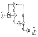
- Figure 1 is a flowchart schematically illustrating an example of an analysis schema of a rule for error management.
- the rule is composed by a set of interconnected steps ST, Al, A2, LOG, CK.
- steps ST, Al, A2, LOG, CK are symbolically denoted with a rounded shape ST, END.
- a first method the execution of already executed step is avoided at run time. In this method, loop-back connections are ignored by the execution engine.
- a rule branch is repeated by encapsulating it in a sub branch labeled as a LOOP, a step that calls a number of times a sub-branch.
- system engineers need to build graphic rules by using a structured programming technique.
- structured programming is not user friendly for system engineers since it does not cover all the possibilities needed by user reasoning on a flowchart schema, especially for error management as in the example of Figure 1 .
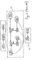
- Figure 2 is a flowchart schematically illustrating an example of a rule for error management in the prior art.
- the flowchart rule approach shown in Figure 2 is an example of structured programming approach, i.e. a rule based graphical language, which makes no use of loop-backs.
- steps are encapsulated in sub-branches S1, S2.
- step LOOP invokes a first sub-branch S1 which begins at step LOOP in sub-branch S1 and which ends at step END LOOP.
- step SUB invoke a second sub-branch S2 and then continues to step LOOP.
- the aforementioned aim is achieved by a method and a system for controlling the re-execution of a rule branch in a rule represented by a graphic flowchart in a manufacturing execution system, the rule branch comprising a set of steps, wherein the flowchart is designed, at engineering time, to comprise a set of interconnected steps denoting a flow of activities to be executed, at run time, by an execution engine; at developing time, defining an additional step, hereinafter denoted as recycle step, wherein the recycle step comprises a conditional expression to be customized, at engineering time, and whose result, each time the recycle step is executed, at run time, is used by the execution engine to decide the rule branch to be executed; wherein the recycle step also comprises an internal counter to keep track, at run time, of the current execution cycle; wherein, the status of the recycle step, each time it is executed at run time, is set by the execution engine as "active" status until the set of steps of the rule branch that follows is executed and then the recycle step status is set as "non-active
- the proposed invention allows system engineers, at engineering time, to use a simple to use flowchart approach for building rules in a MES system while at the same time controlling that the re-execution of rule branches does not lead to infinite loops.
- the rule looks similar to an analysis schema.
- Embodiments of the proposed invention allow the re-using of a shared branch, i.e. when the outputs of two steps are connected to the same rule branch, by queuing subsequent executions.
- the diamond/rhombus indicates that the recycle step RS contains a custom conditional expression, returning a value TRUE or FALSE, to be evaluated at run time, each time the step is executed.
- TRUE or FALSE a value that is evaluated at run time, each time the step is executed.
- the result of this TRUE/FALSE test is used by the execution engine, at run time, to determine the rule execution path that follows.
- the TRUE/FALSE test condition is customized, at engineering time, by the system engineer when he/she, while defining a specific rule, inserts at least one recycle step RS which may be connected to other steps of the rule.
- the recycle step RS contains an internal counter so that, at run time, the current execution cycle can be tracked.
- the reset of the counter is performed only at the rule start.
- the counter of every recycle step in the rule is set to zero.
- the counter of a recycle step is incremented every time the recycle step is executed by the rule engine, until the end of the whole rule execution.
- recycle step RS advantageously enables system engineer of easily programming the maximum number of trials in case of error.
- each time the recycle-step RS is activated it resets runtime data of the steps that follow in order to avoid confusion in subsequent executions of the same rule.
- the execution engine when executing a certain step that is not a recycle step RS , it sets the status of this certain executed step as "already-executed" status and it ignores the execution of steps whose status is "already-executed".
- the execution engine in order to conveniently allow the re-execution of a rule-branch, the execution engine, each time it executes a certain recycle step, it sets the status of steps of the rule branch that follows this certain recycle step RS as "non already-executed" status so that the rule branch can be re-executed.
- a certain recycle step RS When a certain recycle step RS is executed, the execution engine starts the execution of the next steps, and the certain recycle step RS remains active until all of the steps that follow have been executed.
- the rule execution engine is recursive so the control returns to the recycle step when the subsequent rule branch execution has been finished. Because of this, at run time, in case of parallel invocations, the recycle step may act as a semaphore to avoid the parallel execution of the branch that follows. If another branch of the same rule, requests to activate this certain recycle-step RS while this certain recycle-step RS is already/still active, the new request is put on wait until the end of the branch execution is reached, and only then the new request is executed.
- Figure 3 is a flowchart which schematically illustrates an example of a rule for error management according to a first embodiment of the present invention.
- the flowchart rule of Figure 3 is an example of sequential execution with programming with a recycle step RS according to an embodiment of the present invention.
- the checks of failure of the two actions A1, A2 is performed by the recycle step RS.
- the custom conditional expression of the recycle step RS is customized so that, at run time, if input is ERR the recycle step result is TRUE.
- step 3 the execution engine, after having executed the writing error report step LOG, sets the status of this step to "already-executed" status. While, at the start step ST of the rule the status of the log-report step LOG was "non already-executed".
- the execution engine is programmed to ignore the execution of steps A1, A2, LOG - that are not recycle steps RS - whose status is "already-executed".
- Figure 4 is a flowchart which schematically illustrates an example of a rule for error management with parallel execution according to a second embodiment of the present invention.
- the flowchart rule of Figure 4 is an example of three different possible use-cases of the recycle steps RS1, RS2, RS3 inside a flowchart rule.
- Figure 4 shows two parallel loops-back on error LB for error management via the recycle steps RS1.
- Figure 4 shows a recycle-step RS2 used to serialize the parallel usage of the common log-report step LOG, for obtaining a semaphore SEM on shared resources.
- the "semaphore” property is achieved by setting the status of the recycle step RS2, each time it is executed at run time, as "active" status until the set of steps of the rule branch that follows, e.g. log-report step LOG, is executed and then the recycle step status is set as "non-active".
- the execution engine keeps waiting any request of executing the recycle step RS2 if is in "active" status until its status is in "non-active".
- Figure 4 shows a recycle-step RS3 that counts 2 cycles before to terminating the rule.
- the system engineers customize the conditional expression of the recycle step RS3 to return TRUE when its internal counter reaches the value 2.
- Figure 5 is a flowchart which schematically illustrates examples of rules for common iterations according to embodiments of the present invention.
- the flowchart rule of Figure 5 is an example of three different possible use-cases of the recycle steps RS5, RS6 for implementing the most common iterations.
- Fig.5a is an example of "while” or “for” iteration and
- Fig.5b is an example of "repeat until" iteration.
- the recycle step RS5, RS6 acts as a "While” or “For” iteration depending on its location when used before a rule branch (see Fig. 5a ) or as a "Repeat Until” iteration if used after a rule branch (see Fig.5b ).
- the rule engine executes the rule steps in sequence starting from the starting step ST, so if the recycle step RS5 is positioned at the input, i.e. before, of a rule branch it is executed before of the steps in rule branch B1, B2 (See Fig.5a ); instead, if the recycle step is positioned at the output, i.e. after, of a rule branch it will be executed after that the steps in the rule branch (B1, B2) have been executed (See Fig. 5b ).
- the two action steps B1, B2 may be executed in a nested iteration of the type While ⁇ Condition> Do ⁇ Actions>.
- the condition to be fulfilled is customized, at engineering time, by the system engineer.
- the internal counter limit index is customized, at engineering, time by the system engineer.
- the recycle step RS5, RS6, which implements different iteration according to its location in a loop-back, easies the implementation of nested iterations in algorithms at engineering time.
- the system engineers can easily drag and drop, in a graphical way, a recycle step RS in a flowchart rule to switch from a "while” iteration to a "repeat” iteration.
- the recycle step can simplify the existing rules, by rendering the rule more user friendly and by reducing the number of steps in the rule and consequently reducing the allocated memory.
Landscapes
- Engineering & Computer Science (AREA)
- Business, Economics & Management (AREA)
- Theoretical Computer Science (AREA)
- Physics & Mathematics (AREA)
- Strategic Management (AREA)
- Human Resources & Organizations (AREA)
- Entrepreneurship & Innovation (AREA)
- Economics (AREA)
- General Physics & Mathematics (AREA)
- General Engineering & Computer Science (AREA)
- Evolutionary Computation (AREA)
- Data Mining & Analysis (AREA)
- Mathematical Physics (AREA)
- Development Economics (AREA)
- Computing Systems (AREA)
- Educational Administration (AREA)
- Artificial Intelligence (AREA)
- Computational Linguistics (AREA)
- Software Systems (AREA)
- Game Theory and Decision Science (AREA)
- Marketing (AREA)
- Operations Research (AREA)
- Quality & Reliability (AREA)
- Tourism & Hospitality (AREA)
- General Business, Economics & Management (AREA)
- Stored Programmes (AREA)
Abstract
at developing time, defining a recycle step,
wherein the recycle step comprises a conditional expression to be customized, at engineering time,;
wherein the recycle step also comprises an internal counter;
wherein, the status of the recycle step, each time it is executed at run time, is set by the execution engine as "active" status until the set of steps of the rule branch that follows is executed and then the recycle step status is set as "non-active"; wherein, at run time, the execution engine keeps waiting any request of executing a certain recycle step that is in "active" status; wherein, at run time, when the execution engine executes a certain recycle step, it sets the status of the set of steps of the rule branch that follows as "non already-executed" status;
wherein, at run time, the execution engine when it executes a certain step, that is not a recycle step, it sets the status of the certain executed step as "already-executed" status and it ignores the execution of steps whose status is "already-executed"; at engineering time, designing a flowchart rule comprising a set of interconnected steps containing at least one recycle step; at run time, by the execution engine, executing the interconnected step set containing at least one recycle step of the flowchart rule.
Description
- The present invention relates to a method and to a system for controlling the closing of a plant application according the preamble of
claims 1 and 2 respectively. - Software products for industrial control and automation have increased, with time, in scope and refinement, in order to fit the large variety of IT infrastructure requirements of manufacturing companies.
- As defined by the Manufacturing Enterprise Solutions Association (MESA International), a Manufacturing Execution System (MES) "is a dynamic information system that drives effective execution of manufacturing operations", by managing "production operations from point of order release into manufacturing to point of product delivery into finished goods" and by providing "mission critical information about production activities to others across the organization and supply chain via bi-directional communication."
- For example, the Siemens Corp. offers a broad range of MES products, under its SIMATIC® product family.
- As used herein, a software application refers to a set of software components developed by software developers, at developing time, to perform some useful actions within a MES system, e.g. monitoring values coming from plant process or controlling a plant device.
- Typically, at engineering time, system engineers flexibly customize MES applications according to the specific manufacturing plant requirements. The MES application customization at engineering time is an important task in MES applications since often software developers do not have the specific knowledge of a specific plant and they thus develop a more general application.
- It is then the task of the system engineers to customize the MES application to perform specific actions according the specific requirements of a specific manufacturing plant.
- Instead, at runtime, MES applications are utilized by end-users who may be plant operators or line responsible personnel and who typically utilize the MES applications without performing any programming activity.
- The applications in MES system are often conceived as graphical object oriented tools.
- The graphical environment allows system engineers to build their custom functions in a graphical way using a palette of predefined elements and connecting them in order to define a logical flow of operations.
- As used herein, the technical term rule refers to a portion of software comparable to a procedure or a function. It is composed by a set of instructions that are executed by an execution engine. In graphical object oriented programming, the rule is typically graphically represented by a flowchart.
- The flowchart rule is typically composed by blocks interconnected by lines. The blocks represent the instructions to be executed by the execution engine and are called steps. The lines denote the flow of the activity.
- As used herein, the technical term rule branch refers to a portion of a rule, a chain of steps connected together in sequence.
- As used herein, the technical term loop-back or loop refers to a ring of steps connected together in sequence when the output of a step is connected to the input of a previous step in the same rule branch.
- Loops are useful to graphically represent an iteration.
- At engineering time, when system engineers build MES functions in form of graphic rules, they typically expect to be able to use the common flowchart logic, for example by inserting loop-backs.
-
Figure 1 is a flowchart schematically illustrating an example of an analysis schema of a rule for error management. - It is an example of an analysis flowchart made by a system engineer to represent the wanted behaviour of rule for error management.
- The flowchart rule approach shown in
Figure 1 is an example of graphical sequential programming which makes use of loop-backs. - The rule is composed by a set of interconnected steps ST, Al, A2, LOG, CK. Typically, as the skilled in the art knows, the starting and the ending of execution are symbolically denoted with a rounded shape ST, END.
- At runtime, the rule steps described in
Figure 1 are sequentially executed as follows: - Step 0) execution starting ST, going to Step 1)
- Step 1) executing first action A1;
- Step 2) If first action Al fails ERR, then going to Step 3);
- Step 3) writing error report LOG;
go to Step 1); - Step 4) executing second action A2;
- Step 5) If second action A2 fails ERR, then going to Step 3);
- Step 6) execution ending END
- The execution ending of the rule is reached when both first and second actions A1, A2 are executed successfully OK.
- Unfortunately, inserting at engineering time, one or more simple loop-back connections may lead to an out of control behaviour at run time.
- For example, during a serial rule execution, it is difficult to know how many times a branch, which include a sequence of steps, has been executed and it is difficult to determine what the previous executed step was. As a result unexpected infinite loops may be encountered at run time.
- Encountered problems are even more complex if the runtime execution engine is able to manage the parallel execution of more than one branch of the same rule.
- For example, if there is the possibility to execute a common branch more than once at the same time, this may lead to an unpredictable overwrite of the step results.
- The count of each parallel execution in the call stack could easily grow exponentially.
- In order to avoid problems caused by loop-backs, widely used techniques consist in avoiding using loop-backs.
- In a first method, the execution of already executed step is avoided at run time. In this method, loop-back connections are ignored by the execution engine.
- In a second method, strict controls are made at engineering time on the designed flowchart rule in order to avoid loop-backs out of the current branch or to avoid the loop-back at all. In this method, the graphic editor of the rule is complex to develop.
- In a third method, with loop-backs not allowed, a rule branch is repeated by encapsulating it in a sub branch labeled as a LOOP, a step that calls a number of times a sub-branch. In this method, system engineers need to build graphic rules by using a structured programming technique. Unfortunately, structured programming is not user friendly for system engineers since it does not cover all the possibilities needed by user reasoning on a flowchart schema, especially for error management as in the example of
Figure 1 . -
Figure 2 is a flowchart schematically illustrating an example of a rule for error management in the prior art. - The flowchart rule approach shown in
Figure 2 is an example of structured programming approach, i.e. a rule based graphical language, which makes no use of loop-backs. - Instead of using loop-backs, steps are encapsulated in sub-branches S1, S2.
- The resulting graphic schema of
Figure 2 is visually different from the schema ofFigure 1 , even if at run time the rule works as described in the flowchart ofFigure 1 . - At run time, step LOOP invokes a first sub-branch S1 which begins at step LOOP in sub-branch S1 and which ends at step END LOOP.
- Inside sub-branch S1, step SUB invoke a second sub-branch S2 and then continues to step LOOP.
- Thus, as in rule of
Figure 1 , the execution ending of the rule ofFigure 2 is reached when both first and second actions A1, A2 are executed successfully OK. - Unfortunately this kind of graphical programming approach is not user-friendly, nor immediately visible and self-documenting, for system engineers who are required, at engineering time, to build functions according to plant requirements.
- It is therefore the aim of the present invention to overcome the above mentioned drawbacks, in particular by providing a method and a system for controlling the re-execution of a rule branch which is user friendly and reduces the risk of infinite loop-backs in the re-execution of rule branches.
- The aforementioned aim is achieved by a method and a system for controlling the re-execution of a rule branch in a rule represented by a graphic flowchart in a manufacturing execution system, the rule branch comprising a set of steps,
wherein the flowchart is designed, at engineering time, to comprise a set of interconnected steps denoting a flow of activities to be executed, at run time, by an execution engine;
at developing time, defining an additional step, hereinafter denoted as recycle step,
wherein the recycle step comprises a conditional expression to be customized, at engineering time, and whose result, each time the recycle step is executed, at run time, is used by the execution engine to decide the rule branch to be executed;
wherein the recycle step also comprises an internal counter to keep track, at run time, of the current execution cycle;
wherein, the status of the recycle step, each time it is executed at run time, is set by the execution engine as "active" status until the set of steps of the rule branch that follows is executed and then the recycle step status is set as "non-active";
wherein, at run time, the execution engine keeps waiting any request of executing a certain recycle step that is in "active" status until the certain recycle step is in a "non-active" status;
wherein, at run time, when the execution engine executes a certain recycle step, it sets the status of the set of steps of the rule branch that follows as "non already-executed" status if their status was "already executed";
wherein, at run time, the execution engine when it executes a certain step, that is not a recycle step, it sets the status of the certain executed step as "already-executed" status and it ignores the execution of steps whose status is "already-executed";
at engineering time, designing a flowchart rule comprising a set of interconnected steps containing at least one recycle step;
at run time, by the execution engine, executing the interconnected step set containing at least one recycle step of the flowchart rule. - The proposed invention allows system engineers, at engineering time, to use a simple to use flowchart approach for building rules in a MES system while at the same time controlling that the re-execution of rule branches does not lead to infinite loops.
- With the proposed invention, the rule looks similar to an analysis schema.
- It is not necessary to change the execution engine of the rule at run time because the execution of the loop-back is managed by the recycle-step. Thus, advantageously, old applications may continue to work as before.
- Embodiments of the proposed invention simplify the implementation of nested iterations such as 1) While <Condition> Do <Actions>, 2) Repeat <Actions> Until <Condition> and 3) For Index = 1 to X Do <Actions>.
- Embodiments of the proposed invention allow the re-using of a shared branch, i.e. when the outputs of two steps are connected to the same rule branch, by queuing subsequent executions.
- The invention will now be described in preferred but not exclusive embodiments with reference to the accompanying drawings, wherein:
- Figure 1
- flowchart which schematically illustrates an example of an analysis schema of a rule for error management;
- Figure 2
- flowchart which schematically illustrates another example of a rule for error management in the prior art;
- Figure 3
- flowchart which schematically illustrates an example of a rule for error management according to a first embodiment of the present invention;
- Figure 4
- flowchart which schematically illustrates an example of a rule for error management with parallel execution according to a second embodiment of the present invention;
- Figure 5
- flowchart which schematically illustrates examples of rules for common iterations according to embodiments of the present invention.
- In the drawings,
Figures 3 to 5 , the recycle steps RS, RS3, RS5 used for managing the re-execution of rule branch according to the present invention, are graphically represented with a diamond/rhombus with a cyclic arrow inside. - The diamond/rhombus indicates that the recycle step RS contains a custom conditional expression, returning a value TRUE or FALSE, to be evaluated at run time, each time the step is executed. The result of this TRUE/FALSE test is used by the execution engine, at run time, to determine the rule execution path that follows.
- The TRUE/FALSE test condition is customized, at engineering time, by the system engineer when he/she, while defining a specific rule, inserts at least one recycle step RS which may be connected to other steps of the rule.
- The recycle step RS contains an internal counter so that, at run time, the current execution cycle can be tracked.
- The reset of the counter is performed only at the rule start. When a rule starts, the counter of every recycle step in the rule is set to zero. Then, the counter of a recycle step is incremented every time the recycle step is executed by the rule engine, until the end of the whole rule execution.
- This internal counter advantageously allows the recycle step RS to easily implement a "For" nested iteration, e.g. For Index = 1 to X Do <Actions>.
- This feature of the recycle step RS advantageously enables system engineer of easily programming the maximum number of trials in case of error.
At run time, each time the recycle-step RS is activated, it resets runtime data of the steps that follow in order to avoid confusion in subsequent executions of the same rule. - In fact, at run time, the execution engine, when executing a certain step that is not a recycle step RS , it sets the status of this certain executed step as "already-executed" status and it ignores the execution of steps whose status is "already-executed".
However, according to the proposed invention, in order to conveniently allow the re-execution of a rule-branch, the execution engine, each time it executes a certain recycle step, it sets the status of steps of the rule branch that follows this certain recycle step RS as "non already-executed" status so that the rule branch can be re-executed. When a certain recycle step RS is executed, the execution engine starts the execution of the next steps, and the certain recycle step RS remains active until all of the steps that follow have been executed. The rule execution engine is recursive so the control returns to the recycle step when the subsequent rule branch execution has been finished.
Because of this, at run time, in case of parallel invocations, the recycle step may act as a semaphore to avoid the parallel execution of the branch that follows.
If another branch of the same rule, requests to activate this certain recycle-step RS while this certain recycle-step RS is already/still active, the new request is put on wait until the end of the branch execution is reached, and only then the new request is executed. -
Figure 3 is a flowchart which schematically illustrates an example of a rule for error management according to a first embodiment of the present invention. - The flowchart rule of
Figure 3 is an example of sequential execution with programming with a recycle step RS according to an embodiment of the present invention. - The implementation of the rule steps of
Figure 3 is very similar to the analysis schema represented inFigure 1 , using a rule based graphical language as inFigure 2 . - The flowchart schema of
Figure 3 , by resembling to the analysis schema ofFigure 1 , has the advantages of being simple to understand and of being self-documenting and easily visible to system engineers. - At runtime, the rule steps described in
Figure 3 are executed as follows: - Step 0) execution starting ST, going to Step 1)
- Step 1) executing first action A1;
- Step 2) If first action A1 fails ERR, then going to Step 3);
- Step 3) writing error report LOG;
go to Step 1); - Step 4) executing second action A2;
- Step 5) If second action A2 fails ERR, then going to Step 3);
- Stp 6) execution ending END
- At steps 2 and 5, the checks of failure of the two actions A1, A2 is performed by the recycle step RS. At engineering time, the custom conditional expression of the recycle step RS is customized so that, at run time, if input is ERR the recycle step result is TRUE.
- At step 3, the execution engine, after having executed the writing error report step LOG, sets the status of this step to "already-executed" status. While, at the start step ST of the rule the status of the log-report step LOG was "non already-executed".
- The execution engine is programmed to ignore the execution of steps A1, A2, LOG - that are not recycle steps RS - whose status is "already-executed".
- However, each time the recycle step RS is executed the status of the log-report step LOG (which is in the branch that follows) is reset to "non already-executed" status. In this way, a re-execution of the same rule branch is enabled.
- The execution ending of the rule is reached when both first and second actions A1, A2 are executed successfully OK.
-
Figure 4 is a flowchart which schematically illustrates an example of a rule for error management with parallel execution according to a second embodiment of the present invention. - The flowchart rule of
Figure 4 is an example of three different possible use-cases of the recycle steps RS1, RS2, RS3 inside a flowchart rule. - According to the first use-case,
Figure 4 shows two parallel loops-back on error LB for error management via the recycle steps RS1. - According to the second use-case,
Figure 4 shows a recycle-step RS2 used to serialize the parallel usage of the common log-report step LOG, for obtaining a semaphore SEM on shared resources.
The "semaphore" property is achieved by setting the status of the recycle step RS2, each time it is executed at run time, as "active" status until the set of steps of the rule branch that follows, e.g. log-report step LOG, is executed and then the recycle step status is set as "non-active". - At run time, the execution engine keeps waiting any request of executing the recycle step RS2 if is in "active" status until its status is in "non-active".
- According to the third use-case,
Figure 4 shows a recycle-step RS3 that counts 2 cycles before to terminating the rule. - At engineering time, the system engineers customize the conditional expression of the recycle step RS3 to return TRUE when its internal counter reaches the value 2.
- In this third use-case block SYN acts as synchronization point: the end step END is called on the second OK when cycle number equals to 2. In such a manner, as in the previous examples of
Figures 1 to 3 , the execution ending of the rule is reached when both first and second actions A1, A2 are executed successfully OK. -
Figure 5 is a flowchart which schematically illustrates examples of rules for common iterations according to embodiments of the present invention. - The flowchart rule of
Figure 5 is an example of three different possible use-cases of the recycle steps RS5, RS6 for implementing the most common iterations.Fig.5a is an example of "while" or "for" iteration andFig.5b is an example of "repeat until" iteration. - The recycle step RS5, RS6 acts as a "While" or "For" iteration depending on its location when used before a rule branch (see
Fig. 5a ) or as a "Repeat Until" iteration if used after a rule branch (seeFig.5b ). The rule engine executes the rule steps in sequence starting from the starting step ST, so if the recycle step RS5 is positioned at the input, i.e. before, of a rule branch it is executed before of the steps in rule branch B1, B2 (SeeFig.5a ); instead, if the recycle step is positioned at the output, i.e. after, of a rule branch it will be executed after that the steps in the rule branch (B1, B2) have been executed (SeeFig. 5b ). - In
Figure 5a , at run time, the two action steps B1, B2 may be executed in a nested iteration of the type While <Condition> Do <Actions>. In this case, the condition to be fulfilled is customized, at engineering time, by the system engineer. - Alternatively, still in
Figure 5a , at run time, the two action steps B1, B2 may be executed in a nested iteration of the type For Index = 1 to X Do <Actions>. In this case, the internal counter limit index is customized, at engineering, time by the system engineer. - In
Figure 5b , at run time, the two action steps B1, B2 are executed in a nested iteration of the type Repeat <Actions> Until <Condition>. In this case, the condition to be fulfilled is customized, at engineering time, by the system engineer. - Advantageously, the recycle step RS5, RS6, which implements different iteration according to its location in a loop-back, easies the implementation of nested iterations in algorithms at engineering time.
- For example, the system engineers can easily drag and drop, in a graphical way, a recycle step RS in a flowchart rule to switch from a "while" iteration to a "repeat" iteration.
- While example of structured programming approach of
Figure 2 of the prior art, such a switch would have involved programming efforts at engineering time. - The system engineers, with embodiments of the proposed invention, are not required to change the existing rules according to the prior art that will continue to work exactly as before.
- However, the recycle step can simplify the existing rules, by rendering the rule more user friendly and by reducing the number of steps in the rule and consequently reducing the allocated memory.
Claims (2)
- A method for controlling the re-execution of a rule branch in a rule represented by a graphic flowchart in a manufacturing execution system, the rule branch comprising a set of steps (ST, A1, B2),
wherein the flowchart is designed, at engineering time, to comprise a set of interconnected steps (ST, A1, B2) denoting a flow of activities to be executed, at run time, by an execution engine;
at developing time, defining an additional step, hereinafter denoted as recycle step (RS, RS3, RS6),
wherein the recycle step (RS, RS3, RS6) comprises a conditional expression to be customized, at engineering time, and whose result, each time the recycle step (RS, RS3, RS6) is executed, at run time, is used by the execution engine to decide the rule branch to be executed;
wherein the recycle step (RS, RS3, RS6) also comprises an internal counter to keep track, at run time, of the current execution cycle;
wherein, the status of the recycle step (RS, RS3, RS6), each time it is executed at run time, is set by the execution engine as "active" status until the set of steps of the rule branch that follows is executed and then the recycle step status is set as "non-active";
wherein, at run time, the execution engine keeps waiting any request of executing a certain recycle step (RS, RS3, RS6)that is in "active" status until the certain recycle step (RS, RS3, RS6) is in a "non-active" status;
wherein, at run time, when the execution engine executes a certain recycle step (RS, RS3, RS6), it sets the status of the set of steps (ST, A1, B2) of the rule branch that follows as "non already-executed" status if their status was "already executed";
wherein, at run time, the execution engine when it executes a certain step (ST, A1, B2), that is not a recycle step (RS, RS3, RS6), it sets the status of the certain executed step as "already-executed" status and it ignores the execution of steps whose status is "already-executed";
at engineering time, designing a flowchart rule comprising a set of interconnected steps (ST, A1, B2) containing at least one recycle step (RS, RS3, RS6);
at run time, by the execution engine, executing the interconnected step set (ST, A1, B2) containing at least one recycle step (RS, RS3, RS6) of the flowchart rule. - A system having means for performing the steps of the method according to claim 1.
Priority Applications (2)
| Application Number | Priority Date | Filing Date | Title |
|---|---|---|---|
| EP07024733A EP2073155A1 (en) | 2007-12-20 | 2007-12-20 | Controlling the re-execution of a rule branch |
| US12/340,800 US8341596B2 (en) | 2007-12-20 | 2008-12-22 | Method and system for controlling the re-execution of a rule branch |
Applications Claiming Priority (1)
| Application Number | Priority Date | Filing Date | Title |
|---|---|---|---|
| EP07024733A EP2073155A1 (en) | 2007-12-20 | 2007-12-20 | Controlling the re-execution of a rule branch |
Publications (1)
| Publication Number | Publication Date |
|---|---|
| EP2073155A1 true EP2073155A1 (en) | 2009-06-24 |
Family
ID=39586950
Family Applications (1)
| Application Number | Title | Priority Date | Filing Date |
|---|---|---|---|
| EP07024733A Withdrawn EP2073155A1 (en) | 2007-12-20 | 2007-12-20 | Controlling the re-execution of a rule branch |
Country Status (2)
| Country | Link |
|---|---|
| US (1) | US8341596B2 (en) |
| EP (1) | EP2073155A1 (en) |
Families Citing this family (4)
| Publication number | Priority date | Publication date | Assignee | Title |
|---|---|---|---|---|
| CN101803553B (en) * | 2010-04-26 | 2011-07-27 | 西北农林科技大学 | Bubbler root irrigator comprising threaded labyrinth channels |
| EP2682905A1 (en) * | 2012-07-05 | 2014-01-08 | Siemens Aktiengesellschaft | Method and system for handling conditional dependencies between alternative product segments within a manufacturing execution system ANSI/ISA/95 compliant. |
| EP2808784B1 (en) * | 2013-05-30 | 2017-11-29 | Siemens Aktiengesellschaft | A system and a method for creating a graphical user interface within a manufacturing execution system (MES) |
| US11907692B2 (en) * | 2022-07-25 | 2024-02-20 | Bank Of America Corporation | System and method for retrieval and generation of graphical user interface depicting of graphics associated with rules-based data management |
Citations (1)
| Publication number | Priority date | Publication date | Assignee | Title |
|---|---|---|---|---|
| US20050039161A1 (en) * | 2001-12-12 | 2005-02-17 | Gotthard Pfander | System and method for modelling and/or executing software applications, especially mes applications |
Family Cites Families (9)
| Publication number | Priority date | Publication date | Assignee | Title |
|---|---|---|---|---|
| US6006193A (en) * | 1996-12-18 | 1999-12-21 | Gibson; Kenneth U. | Computer executable workflow control system |
| JP3565314B2 (en) * | 1998-12-17 | 2004-09-15 | 富士通株式会社 | Branch instruction execution controller |
| WO2003001365A1 (en) * | 2001-06-22 | 2003-01-03 | Wonderware Corporation | A process control script development and execution facility supporting multiple user-side programming languages |
| DE10161064A1 (en) * | 2001-12-12 | 2003-07-03 | Siemens Ag | System and method for communication between software applications, in particular MES applications |
| US20050149218A1 (en) * | 2003-12-30 | 2005-07-07 | Harry Lube | Project manufacturing method and system |
| US20050210455A1 (en) * | 2004-03-18 | 2005-09-22 | International Business Machines Corporation | Method for generating an executable workflow code from an unstructured cyclic process model |
| US7440811B2 (en) * | 2004-09-28 | 2008-10-21 | Siemens Aktiengesellschaft | Dynamic-state waiting time analysis method for complex discrete manufacturing |
| US7533373B2 (en) * | 2005-01-25 | 2009-05-12 | Taiwan Semiconductor Manufacturing Co., Ltd | Method for prevention of system execution malfunction |
| US7822492B2 (en) * | 2007-10-19 | 2010-10-26 | Ge Intelligent Platforms | Methods and systems for operating an automated system using a process definition model |
-
2007
- 2007-12-20 EP EP07024733A patent/EP2073155A1/en not_active Withdrawn
-
2008
- 2008-12-22 US US12/340,800 patent/US8341596B2/en not_active Expired - Fee Related
Patent Citations (1)
| Publication number | Priority date | Publication date | Assignee | Title |
|---|---|---|---|---|
| US20050039161A1 (en) * | 2001-12-12 | 2005-02-17 | Gotthard Pfander | System and method for modelling and/or executing software applications, especially mes applications |
Non-Patent Citations (3)
| Title |
|---|
| "MES Explained : A High Level Vision", MESA INTERNATIONAL WHITE PAPER, XX, XX, no. 6, 1 September 1997 (1997-09-01), pages 1 - 24, XP002260218 * |
| HARALD STÖRRLE: "Semantics of Structured Nodes in UML 2.0 Activities", NORDIC JOURNAL OF COMPUTING, vol. 11, no. 3, 30 September 2004 (2004-09-30), pages 279 - 302, XP002487797 * |
| MAURER ET AL: "Generalized structured programs and loop trees", SCIENCE OF COMPUTER PROGRAMMING, ELSEVIER SCIENCE PUBLISHERS BV., AMSTERDAM, NL, vol. 67, no. 2-3, 26 June 2007 (2007-06-26), pages 223 - 246, XP022131441, ISSN: 0167-6423 * |
Also Published As
| Publication number | Publication date |
|---|---|
| US20090164879A1 (en) | 2009-06-25 |
| US8341596B2 (en) | 2012-12-25 |
Similar Documents
| Publication | Publication Date | Title |
|---|---|---|
| JPH02211546A (en) | Method and system for mutual exclusive control of resource | |
| CN109983411B (en) | Flow control of program modules | |
| Kheldoun et al. | Specification and verification of complex business processes-a high-level petri net-based approach | |
| US8341596B2 (en) | Method and system for controlling the re-execution of a rule branch | |
| Fuchs et al. | Identification of design patterns for IEC 61131-3 in machine and plant manufacturing | |
| Fabian | On object oriented nondeterministic supervisory control | |
| US8781609B2 (en) | Signal processing network | |
| Yoong et al. | Implementing constrained cyber-physical systems with IEC 61499 | |
| US20190164091A1 (en) | Method for automatic consistency checking after manual intervention in bpmn based workflow execution | |
| Vyatkin et al. | Modeling of IEC 61499 function blocks–a clue to their verification | |
| US7640538B2 (en) | Virtual threads in business process programs | |
| Patig et al. | A pattern-based approach for the verification of business process descriptions | |
| EP2930576A1 (en) | Controlling a manufacturing plant with a MES system | |
| Dai et al. | Applying IEC 61499 design paradigms: Object-oriented programming, component-based design, and service-oriented architecture | |
| Lu et al. | A UML profile to model safety-critical embedded real-time control systems | |
| Owicki | Specifications and proofs for abstract data types in concurrent programs | |
| Falcone et al. | Monitoring distributed component-based systems | |
| Grichi et al. | ROCL: New extensions to OCL for useful verification of flexible software systems | |
| Pierre et al. | A Family-based Framework for i-DSML Adaptation | |
| Telschig et al. | Towards safe dynamic updates of distributed embedded applications in factory automation | |
| Martı́nez et al. | SFC++: a tool for developing distributed real-time control software | |
| Bauer et al. | Towards automatic verification of embedded control software | |
| Tseng et al. | Hierarchical state decomposition for the design of PLC software by applying axiomatic design | |
| Gharbi et al. | Functional and operational solutions for safety reconfigurable embedded control systems | |
| US8561009B2 (en) | Method and apparatus for controlling the closing of a plant application |
Legal Events
| Date | Code | Title | Description |
|---|---|---|---|
| PUAI | Public reference made under article 153(3) epc to a published international application that has entered the european phase |
Free format text: ORIGINAL CODE: 0009012 |
|
| AK | Designated contracting states |
Kind code of ref document: A1 Designated state(s): AT BE BG CH CY CZ DE DK EE ES FI FR GB GR HU IE IS IT LI LT LU LV MC MT NL PL PT RO SE SI SK TR |
|
| AX | Request for extension of the european patent |
Extension state: AL BA HR MK RS |
|
| 17P | Request for examination filed |
Effective date: 20091218 |
|
| AKX | Designation fees paid |
Designated state(s): AT BE BG CH CY CZ DE DK EE ES FI FR GB GR HU IE IS IT LI LT LU LV MC MT NL PL PT RO SE SI SK TR |
|
| 17Q | First examination report despatched |
Effective date: 20110302 |
|
| RAP1 | Party data changed (applicant data changed or rights of an application transferred) |
Owner name: SIEMENS AKTIENGESELLSCHAFT |
|
| GRAP | Despatch of communication of intention to grant a patent |
Free format text: ORIGINAL CODE: EPIDOSNIGR1 |
|
| STAA | Information on the status of an ep patent application or granted ep patent |
Free format text: STATUS: GRANT OF PATENT IS INTENDED |
|
| RIC1 | Information provided on ipc code assigned before grant |
Ipc: G06Q 10/06 20120101ALN20170522BHEP Ipc: G06N 5/02 20060101AFI20170522BHEP |
|
| INTG | Intention to grant announced |
Effective date: 20170606 |
|
| RAP1 | Party data changed (applicant data changed or rights of an application transferred) |
Owner name: SIEMENS AKTIENGESELLSCHAFT |
|
| STAA | Information on the status of an ep patent application or granted ep patent |
Free format text: STATUS: THE APPLICATION IS DEEMED TO BE WITHDRAWN |
|
| 18D | Application deemed to be withdrawn |
Effective date: 20171017 |