EP2073097A2 - Transitioning a processor package to a low power state - Google Patents
Transitioning a processor package to a low power state Download PDFInfo
- Publication number
- EP2073097A2 EP2073097A2 EP08253932A EP08253932A EP2073097A2 EP 2073097 A2 EP2073097 A2 EP 2073097A2 EP 08253932 A EP08253932 A EP 08253932A EP 08253932 A EP08253932 A EP 08253932A EP 2073097 A2 EP2073097 A2 EP 2073097A2
- Authority
- EP
- European Patent Office
- Prior art keywords
- package
- processor
- operation interval
- delay period
- cores
- Prior art date
- Legal status (The legal status is an assumption and is not a legal conclusion. Google has not performed a legal analysis and makes no representation as to the accuracy of the status listed.)
- Granted
Links
- 230000003111 delayed effect Effects 0.000 claims abstract description 8
- 238000000034 method Methods 0.000 claims description 17
- 230000015654 memory Effects 0.000 claims description 16
- 239000000872 buffer Substances 0.000 claims description 4
- 230000000977 initiatory effect Effects 0.000 claims 1
- 238000004422 calculation algorithm Methods 0.000 description 13
- 238000010586 diagram Methods 0.000 description 12
- 230000000694 effects Effects 0.000 description 9
- 239000011159 matrix material Substances 0.000 description 9
- 238000009499 grossing Methods 0.000 description 5
- 238000012545 processing Methods 0.000 description 5
- 230000007704 transition Effects 0.000 description 5
- 230000008569 process Effects 0.000 description 4
- 230000008901 benefit Effects 0.000 description 3
- 238000007726 management method Methods 0.000 description 3
- 241000238876 Acari Species 0.000 description 2
- 230000006870 function Effects 0.000 description 2
- 238000005259 measurement Methods 0.000 description 2
- 238000012986 modification Methods 0.000 description 2
- 230000004048 modification Effects 0.000 description 2
- 230000003287 optical effect Effects 0.000 description 2
- 230000003068 static effect Effects 0.000 description 2
- 238000005309 stochastic process Methods 0.000 description 2
- 238000013459 approach Methods 0.000 description 1
- 238000004364 calculation method Methods 0.000 description 1
- 239000003795 chemical substances by application Substances 0.000 description 1
- 238000004891 communication Methods 0.000 description 1
- 238000013500 data storage Methods 0.000 description 1
- 238000013461 design Methods 0.000 description 1
- 230000009189 diving Effects 0.000 description 1
- 230000005611 electricity Effects 0.000 description 1
- 230000008030 elimination Effects 0.000 description 1
- 238000003379 elimination reaction Methods 0.000 description 1
- 230000002708 enhancing effect Effects 0.000 description 1
- 235000019580 granularity Nutrition 0.000 description 1
- 230000014759 maintenance of location Effects 0.000 description 1
- 238000012544 monitoring process Methods 0.000 description 1
- 230000000737 periodic effect Effects 0.000 description 1
- 230000002093 peripheral effect Effects 0.000 description 1
- 239000004065 semiconductor Substances 0.000 description 1
- 230000001052 transient effect Effects 0.000 description 1
- 230000002618 waking effect Effects 0.000 description 1
Images


Classifications
-
- G—PHYSICS
- G06—COMPUTING; CALCULATING OR COUNTING
- G06F—ELECTRIC DIGITAL DATA PROCESSING
- G06F1/00—Details not covered by groups G06F3/00 - G06F13/00 and G06F21/00
- G06F1/26—Power supply means, e.g. regulation thereof
- G06F1/32—Means for saving power
- G06F1/3203—Power management, i.e. event-based initiation of a power-saving mode
- G06F1/3234—Power saving characterised by the action undertaken
- G06F1/329—Power saving characterised by the action undertaken by task scheduling
-
- Y—GENERAL TAGGING OF NEW TECHNOLOGICAL DEVELOPMENTS; GENERAL TAGGING OF CROSS-SECTIONAL TECHNOLOGIES SPANNING OVER SEVERAL SECTIONS OF THE IPC; TECHNICAL SUBJECTS COVERED BY FORMER USPC CROSS-REFERENCE ART COLLECTIONS [XRACs] AND DIGESTS
- Y02—TECHNOLOGIES OR APPLICATIONS FOR MITIGATION OR ADAPTATION AGAINST CLIMATE CHANGE
- Y02D—CLIMATE CHANGE MITIGATION TECHNOLOGIES IN INFORMATION AND COMMUNICATION TECHNOLOGIES [ICT], I.E. INFORMATION AND COMMUNICATION TECHNOLOGIES AIMING AT THE REDUCTION OF THEIR OWN ENERGY USE
- Y02D10/00—Energy efficient computing, e.g. low power processors, power management or thermal management
-
- Y—GENERAL TAGGING OF NEW TECHNOLOGICAL DEVELOPMENTS; GENERAL TAGGING OF CROSS-SECTIONAL TECHNOLOGIES SPANNING OVER SEVERAL SECTIONS OF THE IPC; TECHNICAL SUBJECTS COVERED BY FORMER USPC CROSS-REFERENCE ART COLLECTIONS [XRACs] AND DIGESTS
- Y02—TECHNOLOGIES OR APPLICATIONS FOR MITIGATION OR ADAPTATION AGAINST CLIMATE CHANGE
- Y02D—CLIMATE CHANGE MITIGATION TECHNOLOGIES IN INFORMATION AND COMMUNICATION TECHNOLOGIES [ICT], I.E. INFORMATION AND COMMUNICATION TECHNOLOGIES AIMING AT THE REDUCTION OF THEIR OWN ENERGY USE
- Y02D30/00—Reducing energy consumption in communication networks
- Y02D30/50—Reducing energy consumption in communication networks in wire-line communication networks, e.g. low power modes or reduced link rate
Definitions
- a core When a core is active, it runs at a so-called C0 state, and when the core is idle, it may be placed in a core low power state, a so-called core non-zero C-state.
- the core C1 state represents the low power state that has the least power savings but can be switched on and off almost immediately, while an extended deep-low power state (e.g., C3) represents a power state where the static power consumption is negligible, but the time to enter into this state and respond to activity (i.e., back to C0) is quite long.
- C3 extended deep-low power state
- Package non-zero C-states enable power consumption at lower levels than the package active state (i.e., C0 state). Server workloads rarely drive all cores in same package busy, but even if only one core is active the whole package (including all idle cores) must stay in a high-power C0 state. Since package non-zero C-state entry/exit latency is relatively long (e.g., on the order of 100 to 200 microseconds ( ⁇ s)), the transient time for all cores being idle usually is not worth using that state, or a performance loss will occur. Thus the OS is unable to take advantage of a package's lower power state benefits, resulting in a package always running at a higher power state than needed.
- Embodiments may reschedule/delay tasks so that the idle time of all cores of a package can be aligned and extended. In this way, more opportunities exist for using greater low power states, i.e., deeper non-zero package C-states.
- Embodiments may operate at relatively fine-granularity, e.g., every 500 microseconds ( ⁇ s), so that latency sensitive workload performance is not degraded. In contrast, a conventional OS scheduler simply leaves all tasks' timing as they are set.
- a predetermined interval e.g., 500 ⁇ s
- the busy times can be stitched to be continuous (i.e., not separated by short idles) so that the idle duration can be extended to accommodate a package deep non-zero C-state's long entry/exit latencies.
- a prediction for future core utilization i.e., for the next operation interval, may be generated. Then, real-time task rescheduling may be performed to enable greater power savings.
- C-states described herein are for an example processor such as an advanced Intel® Architecture 32 (IA-32) processor available from Intel Corporation, Santa Clara, CA, although embodiments can equally be used with other processors. Shown in Table 3 below is an example designation of package C-states available in one embodiment. However, understand that the scope of the present invention is not limited in this regard.
- IA-32 advanced Intel® Architecture 32
- the package is in the C0 state for 70% of the time (where the theoretical perfect case for power savings should be 15%). For the remaining 30% of time that the package could enter a non-zero package C-state, a large portion of the package idle time is for less than 500 ⁇ s, which typically is not worth package C-state entry/exit transition energy cost to enter a deep package low power state.
- embodiments may provide deeper low power states for longer time periods.
- a processor can be scheduled in accordance with an embodiment of the present invention such that it is the active state for only 20% of the time and a deeper low power state (e.g., package C3) for 80% of the time.
- system 10 may be a computer system such as a desktop, server or laptop computer.
- System 10 may include at least one processor package 50 that includes multiple cores 55 a and 55 b (generically core 55) and a timer 58, which as will be described further below, acts as a watchdog timer. While shown with only two such cores in the embodiment of FIG. 1 , understand the scope of the present invention is not limited in this regard and embodiments may be used in many-core systems.
- many implementations may be adapted in a system such as a server system having multiple processor packages.
- utilization information from cores 55 may be provided to a core utilization monitor 20.
- Monitor 20 may be a real-time monitor to capture all cores' central processing unit (CPU) utilization during the monitored interval (e.g., every 500 ⁇ s).
- CPU central processing unit
- the monitored data from monitor 20 may be provided to a predictor 30.
- Predictor 30 may be used to predict future core utilization.
- a Kalman filter algorithm prediction of computational complexity O(n) may be performed, where n is number of cores in the same package, such that the prediction can be done in real time.
- predictor 30 may provide information to an OS scheduler 40 regarding its predictions of the core utilization, which may be on a utilization percentage basis.
- OS scheduler 40 may perform embodiments of the present invention to enable transitioning of the processor package to a lower power state. For example, using embodiments of the present invention, tasks, interrupts and break events to be scheduled on the various cores 55 may be delayed to enable a longer and more continuous idle period in which package 50 can be placed in a deeper low power state. Furthermore, package 50 may remain in this selected low power state for a longer time duration. At the conclusion of this extended idle period, which may be referred to herein as a delay period, the various cores of package 50 may be activated to perform any pending tasks, interrupts or other break events that may have been buffered during the delay period.
- all incoming break events and tasks can be delayed for the duration of the delay period, referred to herein as a time T* (and which may vary in each operation interval). After that time, all break events and tasks will be serviced.
- a watchdog timer 58 may be set with an initial value T*. Note that while in some embodiments, timer 58 may be present in each core 55, in other implementations only a single package timer may be present. When this timer expires, it will create a non-maskable interrupt and wake the corresponding core 55. Cores 55 may then service tasks and break events. In various embodiments buffers 45 a and 45 b may keep all interrupts received before the watchdog timer expires. Note while shown being coupled between OS scheduler 40 and package 50, such buffers may be associated with various system agents coupled to package 50, such as chipsets, input/output (I/O) devices, peripherals and so forth.
- I/O input/output
- monitor 20, predictor 30, and scheduler 40 all may be implemented using circuitry of package 50 such as a given core 55, executing software or firmware in accordance with an embodiment of the present invention.
- OS scheduler 40 may be a given OS adapted to perform rescheduling of tasks within a utilization cycle from their original timing until after the delay period.
- PMU performance management unit
- method 100 may be used to determine an idle state for a processor package and control operation of the processor package to be in a low power state for this idle period.
- method 100 may begin by receiving prediction information (block 110).
- the prediction information corresponds to utilization rates for each core of a package during a utilization period, which may be a relatively short time period (i.e., 500 ⁇ s).
- a Kalman filter model may be used to generate the predictions.
- a KFM models a partially observed stochastic process with linear dynamics and linear observations, both subject to Gaussian noise. It is an efficient recursive filter that estimates the state of a dynamic system from a series of incomplete and noisy measurements.
- x 1 ( x 1 ...x t ,), is also represented as a vector of real numbers.
- nxn transition matrix A in the difference Equation 4 relates the state at the previous t-1 time step to the state at the current step t, in the absence of either a driving function or process noise.
- n is the number of hidden states.
- m n is the number of possible CPU activity states.
- 0 are the initial mean and variance of the sate
- Q is the system covariance for the transition dynamic noises
- R is the observation covariance for the observation noises.
- the transition of observation functions is the same for all time and the model is said to be time-invariant or homogeneous.
- y 1: t ) ,L > 0, where L is the lag, e.g., we might want to figure out whether a pipe broke L minutes ago given the current sensor readings. This is traditionally called “fixed-lag smoothing", although the term “hindsight" might be more appropriate. In the offline case, this is called (fixed-interval) smoothing; this corresponds to computing P ( X T-L x
- Table 1 shows the pseudo code of the prediction algorithm.
- the computation as set forth in Table 1 can be complicated, e.g., there are matrix inversions in the T+1 step loop, when computing Kalman gain matrix in Fwd operator and the smoother gain matrix in Back operator. And the computational complexity will be O(TN 3 ), where T is the number of history observations; N is the number of activity states, because for a general N*N matrix, Gaussian elimination for solving the matrix inverse leads to O(N 3 ) complexity.
- the algorithm implementation can be simplified.
- processor package activity states can be classified into 3 patterns: all idle, all busy and partial idle, and we use these three patterns to describe the states, so N would become only 3.
- KFM KFM and set A, C, Q, R and initial V as a diagonal matrix with the element values being 0 or 1, to reduce the operation complexity of the algorithm to O(N). While described using this prediction algorithm, embodiments of the present invention are not limited in this regard.
- an idle period may be set (block 120).
- blocks 110 and 120 may be implemented in various locations in different embodiments. In one particular embodiment, these blocks may be implemented in an OS, such as within an OS scheduler, although the scope of the present invention is not limited in this regard.
- next the processor package may be controlled to be in a package low power state for the idle period (block 130). As will be discussed further below, this low power state may be a deeper low power state than otherwise may be possible. This is so, as the idle period can be a continuous period from the beginning of a next utilization cycle until an active period, which corresponds to the difference between the next utilization cycle length and the idle period length.
- This control of the processor package may be implemented by receiving OS commands to place the processor package into the selected low power state. However, in other implementations the processor package itself may determine an appropriate low power state based on the duration of the idle period and all its cores' deepest C-state.
- the processor package may be controlled to be in a package active power state (block 140), such as the package C0 state, although the scope of the present invention is not limited in this regard. While shown with this particular implementation in the embodiment of FIG. 2 , the scope of the present invention is not limited in this regard.
- method 300 may be implemented by an OS scheduler to receive utilization prediction information and reschedule activities on a package to enable a delay period to be realized such that the package can enter into a low power state, and in many implementations a deep low power state, for the duration of the delay period.
- method 300 may begin by receiving predicted core utilization information (block 310). More specifically, in various embodiments a predictor, such as predictor 30 of FIG. 1 may provide, for each core of a package, a predicted core utilization to the OS scheduler. In some embodiments, this prediction may be a core utilization value, U_coreX, for each core of the package. In one such embodiment, this utilization value may correspond to a percentage, indicating a predicted percentage of time for a next operation interval in which the core is predicted to be in an active state. However the scope of the present invention is not limited in this regard. For example, in other implementations the percentage information may be a pattern distribution for predicted core states for the next interval.
- Such pattern distribution may vary widely, depending on a number of low power states supported, as well as a given number of cores, length of the prediction period and so forth.
- a pattern distribution can include three different idle-active patterns, although more or fewer such patterns may be provided, e.g., with varying granularities as to a number of cores at a given activity level.
- a maximum utilization rate, U_max may be set equal to this predicted value (block 320).
- a delay period, T* may be set based on this predicted maximum utilization rate. For example, for a next operation interval (NOI), T* may be set equal to NOI x (100%-U_max), where U_max is expressed as a percentage.
- the package may be placed into a package low power state, such as a package C1 state, although given that the delay period is for an extended and deterministic time, the package can be placed into a deeper low power state, such as the package C3 state, although the scope of the present invention is not limited in this regard.
- a package low power state such as a package C1 state
- the package can be placed into a deeper low power state, such as the package C3 state, although the scope of the present invention is not limited in this regard.
- a deeper package low power state such as a package C6 or C7 state may be entered. Accordingly, for the time of the delay period, the package may remain in this low power state, thus enabling configurable and deeper power savings.
- This low power state may thus remain in effect until the package watchdog timer expires (block 360).
- the package may transition from its low power state to the active C0 state.
- any break events that have been buffered may be fetched (block 370).
- one or more devices coupled to the package may have buffered break events destined to the package.
- these break events may be fetched.
- the break events may be serviced in their original timing. That is, the buffered break events may be serviced in the order in which they were buffered (e.g., on a first in first out basis).
- any tasks scheduled for the core may then be performed according to their original timing. That is, after handling the break events any tasks scheduled to each core may be processed in the order of their original scheduling. While shown with this particular implementation in the embodiment of FIG. 4 , the scope of the present invention is not limited in this regard and other manners of delaying processing of tasks and break events on a package may be realized to enable relatively long, continuous idle periods in which the package can be placed in a package low power state.
- Example processor power specifications and power consumption using a conventional scheduling and in accordance with one embodiment of the present invention for an example 15% system load level are shown in Table 2.
- FIG. 5 shown is a timing diagram of scheduling tasks to multiple cores of a package according to a conventional OS scheduling algorithm and according to an embodiment of the present invention.
- Schedule A corresponds to a conventional scheduling.
- an activity interval which may correspond to 500 ⁇ s
- both cores may be in an idle state (represented by a dashed line) and thus the package may be placed into the package C1 state. That is, although both cores are idle, because tasks are scheduled onto both cores in the near future, the latency needed to enter into a greater low power state exceeds its benefit.
- the package is placed only into the package C1 state.
- the package is transitioned to the active C0 state, as from that time forward at least one of the two cores is busy (the active state is represented by the solid lines) executing tasks or other operations.
- a delay period corresponding to time duration 430 is provided at a beginning of the operation interval. Because of the extended duration of this delay period 430, which may be 425 ⁇ s, the package may be placed in a deeper low power state, e.g., a package C3 state (or even deeper C-state), thus enabling greatly enhanced power savings, on the order of approximately 60% more than that of schedule A. At the conclusion of this delay period 430, the package is placed into the active state and thus for the remaining duration of the operation interval, the package is in the package C0 state for time duration 440. While not shown in FIG.
- core low power states e.g., core C-states
- all cores may be in the active state at a beginning of the active period, and as tasks and break events are completed, individual cores can be placed into a core low power state.
- core low power states e.g., core C-states
- all cores may be in the active state at a beginning of the active period, and as tasks and break events are completed, individual cores can be placed into a core low power state.
- core low power states e.g., core C-states
- Table 3 shows package C-states and their descriptions, along with the estimated power consumption in these states, with reference to an example processor having a thermal design power (TDP) of 130 watts (W).
- TDP thermal design power
- W watts
- Table 3 Description Estimated power consumption Package (Pkg) C0 All uncore and core logics active 130W Pkg C1 All cores inactive, package (pkg) clockgated 28W Pkg C3 Pkg C1 state + all external links to long-latency idle states + put memory in short-latency inactive state 18W Pkg C6 Pkg C3 state + reduced voltage for powerplane (only very low retention voltage remains) + put memory in long-latency inactive state 10W Pkg C7 Pkg C6 state + last level cache (LLC) shrunk 5W
- OS-based scheduling embodiments are not limited in this regard. That is, in other implementations, software, firmware or hardware may be adapted on a package basis or at another location within a system, such as a power management unit (PMU) to enable dynamic rescheduling of tasks within an operating interval such that extended, continuous idle periods within each operating interval may be realized, enhancing the ability to enter into extended and deeper low power states on a package basis.
- PMU power management unit
- FIG. 5 shows the delay period at the beginning of an operation interval, the scope of the present invention is not limited in this regard and in other implementations, processing may be performed up front, followed by the delay period.
- multiprocessor system 500 is a point-to-point interconnect system, and includes a first processor 570 and a second processor 580 coupled via a point-to-point interconnect 550.
- processors 570 and 580 may be multicore processors, including first and second processor cores (i.e., processor cores 574a and 574b and processor cores 584a and 584b), although additional cores may be present in the processors.
- Each processor 570 and 580 may be controlled to be in a lower package C* state as a delay period T* can be determined and set.
- Each processor may further include hardware, software, firmware or combinations thereof to enable monitoring of utilization, and generating and using prediction information to enable determination of a delay period for a next operation interval in accordance with an embodiment of the present invention.
- first processor 570 further includes a memory controller hub (MCH) 572 and point-to-point (P-P) interfaces 576 and 578.
- second processor 580 includes a MCH 582 and P-P interfaces 586 and 588.
- MCH's 572 and 582 couple the processors to respective memories, namely a memory 532 and a memory 534, which may be portions of main memory (e.g., a dynamic random access memory (DRAM)) locally attached to the respective processors.
- First processor 570 and second processor 580 may be coupled to a chipset 590 via P-P interconnects 552 and 554, respectively.
- chipset 590 includes P-P interfaces 594 and 598.
- chipset 590 includes an interface 592 to couple chipset 590 with a high performance graphics engine 538, by a P-P interconnect 539.
- chipset 590 may be coupled to a first bus 516 via an interface 596.
- various I/O devices 514 may be coupled to first bus 516, along with a bus bridge 518 which couples first bus 516 to a second bus 520.
- Various devices may be coupled to second bus 520 including, for example, a keyboard/mouse 522, communication devices 526 and a data storage unit 528 such as a disk drive or other mass storage device which may include code 530, in one embodiment.
- an audio I/O 524 may be coupled to second bus 520.
- Embodiments may be implemented in code and may be stored on a storage medium having stored thereon instructions which can be used to program a system to perform the instructions.
- the storage medium may include, but is not limited to, any type of disk including floppy disks, optical disks, compact disk read-only memories (CD-ROMs), compact disk rewritables (CD-RWs), and magneto-optical disks, semiconductor devices such as read-only memories (ROMs), random access memories (RAMs) such as dynamic random access memories (DRAMs), static random access memories (SRAMs), erasable programmable read-only memories (EPROMs), flash memories, electrically erasable programmable read-only memories (EEPROMs), magnetic or optical cards, or any other type of media suitable for storing electronic instructions.
- ROMs read-only memories
- RAMs random access memories
- DRAMs dynamic random access memories
- SRAMs static random access memories
- EPROMs erasable programmable read-only memories
- EEPROMs electrical
Abstract
Description
- Power and thermal management are becoming more challenging than ever before in all segments of computer-based systems. While in the server domain, the cost of electricity drives the need for low power systems, in mobile systems battery life and thermal limitations make these issues relevant. Optimizing a system for maximum performance at minimum power consumption is usually done using the operating system (OS) to control hardware elements. Most modem OS's use the Advanced Configuration and Power Interface (ACPI) standard, e.g., Rev. 3.0b, published October 10, 2006, for optimizing the system in these areas. An ACPI implementation allows a core to be in different power-saving states (also termed low power or idle states) generally referred to as so-called C1 to Cn states. Similar package C-states exist for package-level power savings.
- When a core is active, it runs at a so-called C0 state, and when the core is idle, it may be placed in a core low power state, a so-called core non-zero C-state. The core C1 state represents the low power state that has the least power savings but can be switched on and off almost immediately, while an extended deep-low power state (e.g., C3) represents a power state where the static power consumption is negligible, but the time to enter into this state and respond to activity (i.e., back to C0) is quite long.
- Package non-zero C-states enable power consumption at lower levels than the package active state (i.e., C0 state). Server workloads rarely drive all cores in same package busy, but even if only one core is active the whole package (including all idle cores) must stay in a high-power C0 state. Since package non-zero C-state entry/exit latency is relatively long (e.g., on the order of 100 to 200 microseconds (µs)), the transient time for all cores being idle usually is not worth using that state, or a performance loss will occur. Thus the OS is unable to take advantage of a package's lower power state benefits, resulting in a package always running at a higher power state than needed.
-
-
FIG. 1 is a block diagram of a portion of a system in accordance with one embodiment of the present invention. -
FIG. 2 is a flow diagram of a method in accordance with one embodiment of the present invention. -
FIG. 3 is a flow diagram of a prediction algorithm in accordance with one embodiment of the present invention. -
FIG. 4 is a flow diagram of a rescheduling method in accordance with one embodiment of the present invention. -
FIG. 5 is a timing diagram of scheduling tasks in accordance with an embodiment of the present invention. -
FIG. 6 is a block diagram of a system in accordance with an embodiment of the present invention. - Embodiments may reschedule/delay tasks so that the idle time of all cores of a package can be aligned and extended. In this way, more opportunities exist for using greater low power states, i.e., deeper non-zero package C-states. Embodiments may operate at relatively fine-granularity, e.g., every 500 microseconds (µs), so that latency sensitive workload performance is not degraded. In contrast, a conventional OS scheduler simply leaves all tasks' timing as they are set.
- In various embodiments, a predetermined interval, e.g., 500µs, may be set and during each interval break-event processing may be delayed to make cores in the same package idle together and busy together. Further, the busy times can be stitched to be continuous (i.e., not separated by short idles) so that the idle duration can be extended to accommodate a package deep non-zero C-state's long entry/exit latencies. As described below, a prediction for future core utilization, i.e., for the next operation interval, may be generated. Then, real-time task rescheduling may be performed to enable greater power savings. Note that the C-states described herein are for an example processor such as an advanced Intel® Architecture 32 (IA-32) processor available from Intel Corporation, Santa Clara, CA, although embodiments can equally be used with other processors. Shown in Table 3 below is an example designation of package C-states available in one embodiment. However, understand that the scope of the present invention is not limited in this regard.
- Using a conventional scheduling algorithm, for example a workload at a 15% system load level, the package is in the C0 state for 70% of the time (where the theoretical perfect case for power savings should be 15%). For the remaining 30% of time that the package could enter a non-zero package C-state, a large portion of the package idle time is for less than 500µs, which typically is not worth package C-state entry/exit transition energy cost to enter a deep package low power state. Assume the follow power consumption levels for an example processor in the package C0, C1, and C3 states:
- Power(C0)=130Watts (W)
- Power(C1)=28W
- Power(C3)=18W
- The power consumed in this example using a conventional scheduling policy, is:

- In contrast, embodiments may provide deeper low power states for longer time periods. For example, in comparison to the above calculation, a processor can be scheduled in accordance with an embodiment of the present invention such that it is the active state for only 20% of the time and a deeper low power state (e.g., package C3) for 80% of the time. In this case, the processor consumes:

- Referring now to
FIG. 1 , shown is a block diagram of a portion of a system in accordance with one embodiment of the present invention. As shown inFIG. 1 ,system 10 may be a computer system such as a desktop, server or laptop computer.System 10 may include at least oneprocessor package 50 that includesmultiple cores 55a and 55b (generically core 55) and atimer 58, which as will be described further below, acts as a watchdog timer. While shown with only two such cores in the embodiment ofFIG. 1 , understand the scope of the present invention is not limited in this regard and embodiments may be used in many-core systems. Furthermore, instead of asingle package 50, many implementations may be adapted in a system such as a server system having multiple processor packages. As shown inFIG. 1 , utilization information fromcores 55 may be provided to acore utilization monitor 20.Monitor 20 may be a real-time monitor to capture all cores' central processing unit (CPU) utilization during the monitored interval (e.g., every 500µs). In one embodiment, the formula to compute utilization, U, is as follows: U = delta of unhalted core reference clockticks/delta of TimeStamp Counter [EQ. 3]
where the unhalted clock ticks are clock ticks occurring when the core is active and timestamp counter is a timestamp of total processor cycles during the monitored interval. The monitored data frommonitor 20 may be provided to apredictor 30. -
Predictor 30 may be used to predict future core utilization. In one embodiment, a Kalman filter algorithm prediction of computational complexity O(n) may be performed, where n is number of cores in the same package, such that the prediction can be done in real time. For each prediction interval (e.g., 500µs),predictor 30 may provide information to anOS scheduler 40 regarding its predictions of the core utilization, which may be on a utilization percentage basis. - In various embodiments,
OS scheduler 40 may perform embodiments of the present invention to enable transitioning of the processor package to a lower power state. For example, using embodiments of the present invention, tasks, interrupts and break events to be scheduled on thevarious cores 55 may be delayed to enable a longer and more continuous idle period in whichpackage 50 can be placed in a deeper low power state. Furthermore,package 50 may remain in this selected low power state for a longer time duration. At the conclusion of this extended idle period, which may be referred to herein as a delay period, the various cores ofpackage 50 may be activated to perform any pending tasks, interrupts or other break events that may have been buffered during the delay period. - Thus based on the predicted core utilizations for the next interval, all incoming break events and tasks can be delayed for the duration of the delay period, referred to herein as a time T* (and which may vary in each operation interval). After that time, all break events and tasks will be serviced.
- Since the OS' periodic timer interrupt is also delayed, on each core a
watchdog timer 58 may be set with an initial value T*. Note that while in some embodiments,timer 58 may be present in eachcore 55, in other implementations only a single package timer may be present. When this timer expires, it will create a non-maskable interrupt and wake thecorresponding core 55.Cores 55 may then service tasks and break events. In various embodiments buffers 45a and 45b may keep all interrupts received before the watchdog timer expires. Note while shown being coupled betweenOS scheduler 40 andpackage 50, such buffers may be associated with various system agents coupled topackage 50, such as chipsets, input/output (I/O) devices, peripherals and so forth. - When all cores are idle after rescheduling of tasks, the low-power non-zero package C-state may be entered by processor hardware logic. While shown with this particular implementation in the embodiment of
FIG. 1 , the scope of the present invention is not limited in this regard. In some embodiments, monitor 20,predictor 30, andscheduler 40 all may be implemented using circuitry ofpackage 50 such as a givencore 55, executing software or firmware in accordance with an embodiment of the present invention. Further,OS scheduler 40 may be a given OS adapted to perform rescheduling of tasks within a utilization cycle from their original timing until after the delay period. However, other embodiments may be implemented in other locations such as a performance management unit (PMU) of a given platform. - Referring now to
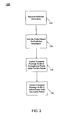
FIG. 2 , shown is a flow diagram of a method in accordance with one embodiment of the present invention. As shown inFIG. 2 ,method 100 may be used to determine an idle state for a processor package and control operation of the processor package to be in a low power state for this idle period. - Specifically, as shown in
FIG. 2 ,method 100 may begin by receiving prediction information (block 110). As an example, the prediction information corresponds to utilization rates for each core of a package during a utilization period, which may be a relatively short time period (i.e., 500 µs). - Different predictions may be made in different embodiments. In one embodiment, a Kalman filter model (KFM) may be used to generate the predictions. A KFM models a partially observed stochastic process with linear dynamics and linear observations, both subject to Gaussian noise. It is an efficient recursive filter that estimates the state of a dynamic system from a series of incomplete and noisy measurements. Based on a KFM, the CPU package activity as set forth in a number of predetermined patterns associated with idle-busy states of the package's core (e.g., a percentage of a number of predetermined idle-busy patterns) are considered the observations of a real number stochastic process discretised in the time domain, denoted by y 1:t = (y 1,...yt ). The hidden state of the process, x 1:t = (x 1...x t ,), is also represented as a vector of real numbers. The linear stochastic different equation in KFM is:

And the measurement equation is:
- The nxn transition matrix A in the difference Equation 4 relates the state at the previous t-1 time step to the state at the current step t, in the absence of either a driving function or process noise. Here n is the number of hidden states. In our task, m = n is the number of possible CPU activity states. x 1|0,V 1|0 are the initial mean and variance of the sate, Q is the system covariance for the transition dynamic noises, and R is the observation covariance for the observation noises. The transition of observation functions is the same for all time and the model is said to be time-invariant or homogeneous.
- Using KFM, values can be predicted on the future time, given all the observations up to the present time. However, we are generally unsure about the future, and thus a best guess is computed, as well as a confidence level. Hence a probability distribution over the possible future observations is computed, denoted by P(Y t+h = y|y 1:t ), where k>0 is the horizon, i.e., how far into the future to predict.
- Given the sequence of observed values (y1-yt), to predict the new observation value is to compute P(Yt+h = y :tlz) for some horizon k>0 into the future. Equation 6 is the computation of a prediction about the future observations by marginalizing out the prediction of the future hidden state.

- A fixed-lag Kalman smoother (FLKS) is an approach to perform retrospective data assimilation. It estimates the state of the past, given all the evidence up to the current time, i.e., P(Xt-L = x|y 1:t ),L > 0, where L is the lag, e.g., we might want to figure out whether a pipe broke L minutes ago given the current sensor readings. This is traditionally called "fixed-lag smoothing", although the term "hindsight" might be more appropriate. In the offline case, this is called (fixed-interval) smoothing; this corresponds to computing P(XT-L = x|y 1:T ),T ≥ L ≥ 1.
- In the prediction algorithm, there are h more forward and backward passes. The computation of the passes is similar to that in the smoothing process. The only difference is that in the prediction step the initial value of the new observation is null, which means


- Table 1 shows the pseudo code of the prediction algorithm.

- In Table 1, Fwd and Back are the abstract operators. For each Fwd (forwards pass) operation of the first loop (for t=1:T), we firstly compute the inference mean and variance by x t|t-1 = Ax t-1|t-1 and V t|t-1 = AV t-1|t-1 A'+Q; then compute the error in the inference (the innovation), the variance of the error, the Kalman gain matrix, and the conditional log-likelihood of this observation by errt = yt - Cx t|t-1, St = CV t|t-1 C'+R, Kt = V t|t-1 C'St -1 , and Lt = log(N(errt ;0,St ) respectively; finally we update the estimates of the mean and variance by x t|t = x t|t-1 + Kterrt, and V t|t = V t|t-1 - KtStKt '.
- For each Back (backwards pass) operation of the second loop (for t=T-1:-1:1), at first we compute the inference quantities by x t+1|t = Ax t|t and V t+1|t = AV t|t A'+Q; then compute the smoother gain matrix by

- The computation as set forth in Table 1 can be complicated, e.g., there are matrix inversions in the T+1 step loop, when computing Kalman gain matrix in Fwd operator and the smoother gain matrix in Back operator. And the computational complexity will be O(TN3), where T is the number of history observations; N is the number of activity states, because for a general N*N matrix, Gaussian elimination for solving the matrix inverse leads to O(N3) complexity. However, in various embodiments the algorithm implementation can be simplified.
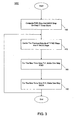
- As shown in
FIG. 3 , which is a flow diagram of aprediction algorithm 150 in accordance with one embodiment of the present invention, the forward and back operations can be computed for a predicted number of intervals (e.g., time slices T=1000) (block 160). Then the previous T step intermediate result of x and V can be cached (block 170), and just one step update of Fwd is made for the new coming time slice T+1 (block 180). Similarly, for the backwards pass, just one step Back operator for the T+1 time slice can be computed (block 190), using the cached previous T step intermediate results. Hence after the simplification, the computational complexity would be O(N3). Furthermore, the N=2N' (N' is the number of cores inside the same package) processor package activity states can be classified into 3 patterns: all idle, all busy and partial idle, and we use these three patterns to describe the states, so N would become only 3. On the other hand, we simplify the KFM and set A, C, Q, R and initial V as a diagonal matrix with the element values being 0 or 1, to reduce the operation complexity of the algorithm to O(N). While described using this prediction algorithm, embodiments of the present invention are not limited in this regard. - Referring back to
FIG. 2 , based on this prediction information, an idle period may be set (block 120). Note that blocks 110 and 120 may be implemented in various locations in different embodiments. In one particular embodiment, these blocks may be implemented in an OS, such as within an OS scheduler, although the scope of the present invention is not limited in this regard.
Referring still toFIG. 2 , next the processor package may be controlled to be in a package low power state for the idle period (block 130). As will be discussed further below, this low power state may be a deeper low power state than otherwise may be possible. This is so, as the idle period can be a continuous period from the beginning of a next utilization cycle until an active period, which corresponds to the difference between the next utilization cycle length and the idle period length. This control of the processor package may be implemented by receiving OS commands to place the processor package into the selected low power state. However, in other implementations the processor package itself may determine an appropriate low power state based on the duration of the idle period and all its cores' deepest C-state. - At the conclusion of the idle period, the active period is initiated and thus the processor package may be controlled to be in a package active power state (block 140), such as the package C0 state, although the scope of the present invention is not limited in this regard. While shown with this particular implementation in the embodiment of
FIG. 2 , the scope of the present invention is not limited in this regard. - Referring now to
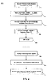
FIG. 4 , shown is a flow diagram of a rescheduling method in accordance with one embodiment of the present invention. As shown inFIG. 4 ,method 300 may be implemented by an OS scheduler to receive utilization prediction information and reschedule activities on a package to enable a delay period to be realized such that the package can enter into a low power state, and in many implementations a deep low power state, for the duration of the delay period. - As shown in
FIG. 4 ,method 300 may begin by receiving predicted core utilization information (block 310). More specifically, in various embodiments a predictor, such aspredictor 30 ofFIG. 1 may provide, for each core of a package, a predicted core utilization to the OS scheduler. In some embodiments, this prediction may be a core utilization value, U_coreX, for each core of the package. In one such embodiment, this utilization value may correspond to a percentage, indicating a predicted percentage of time for a next operation interval in which the core is predicted to be in an active state. However the scope of the present invention is not limited in this regard. For example, in other implementations the percentage information may be a pattern distribution for predicted core states for the next interval. Such pattern distribution may vary widely, depending on a number of low power states supported, as well as a given number of cores, length of the prediction period and so forth. As one example, a pattern distribution can include three different idle-active patterns, although more or fewer such patterns may be provided, e.g., with varying granularities as to a number of cores at a given activity level. - Next, the core with the highest predicted utilization rate may be identified and a maximum utilization rate, U_max, may be set equal to this predicted value (block 320). Furthermore, a delay period, T*, may be set based on this predicted maximum utilization rate. For example, for a next operation interval (NOI), T* may be set equal to NOI x (100%-U_max), where U_max is expressed as a percentage.
- Referring still to
FIG. 4 , at the beginning of the next interval (i.e., at the beginning of a next 500µs cycle), all task processing and break-event servicing may be stopped on each core (block 330). Furthermore, on each package, a watchdog timer may be registered to a time equal to the delay period, T* (block 340). Then the cores of the package may be idled (block 350). Thus at this time, the package may be placed into a package low power state, such as a package C1 state, although given that the delay period is for an extended and deterministic time, the package can be placed into a deeper low power state, such as the package C3 state, although the scope of the present invention is not limited in this regard. For example, in other implementations based on the core utilization information, if the delay period is set to be longer than a given threshold (e.g., 20% of the 500µs interval), a deeper package low power state such as a package C6 or C7 state may be entered. Accordingly, for the time of the delay period, the package may remain in this low power state, thus enabling configurable and deeper power savings. - This low power state may thus remain in effect until the package watchdog timer expires (block 360). At this time, the package may transition from its low power state to the active C0 state. Then on each core, any break events that have been buffered may be fetched (block 370). For example, during the delay period in which the package is in an idle state, one or more devices coupled to the package may have buffered break events destined to the package. Thus, upon waking of the individual cores, these break events may be fetched. Accordingly, at
block 380, the break events may be serviced in their original timing. That is, the buffered break events may be serviced in the order in which they were buffered (e.g., on a first in first out basis). After servicing of any break events, any tasks scheduled for the core may then be performed according to their original timing. That is, after handling the break events any tasks scheduled to each core may be processed in the order of their original scheduling. While shown with this particular implementation in the embodiment ofFIG. 4 , the scope of the present invention is not limited in this regard and other manners of delaying processing of tasks and break events on a package may be realized to enable relatively long, continuous idle periods in which the package can be placed in a package low power state. - In contrast to embodiments such as described above, using a conventional OS scheduler, tasks and break events are serviced immediately, causing cores and the package to frequently to enter and exit idle states. Since periods of minimal idles do not permit use of long-latency and low-power deep package C-states, only the package C1 state can be used. Also conventional OS scheduler cores' busy times are not overlapped, causing a package to remain in C0 while only a single core is busy. Assume using conventional scheduling that of a 500µs period, the total time spent in the package C0 state is 125µs, and total time in the package C1 state is 375µs. Instead, using an embodiment of the present invention predicting a first core's utilization of 10% and a second core's utilization of 15%, then the maximum core's utilization (U_max) is 15%. Accordingly, the determined delay period T* may be set as follows:

where U_max is expressed as a percentage (i.e., 15% is expressed as 15). In this case, T*=500*(100% - 15%) = 425µs, and the package in the coming 500µs will get 425µs of continuous idle time, which can enable a deeper low power state such as the package C3 state. Thereafter the 425µs watchdog timer expires, the package returns to the C0 state and each core will process all tasks and break events in their original timing. Example processor power specifications and power consumption using a conventional scheduling and in accordance with one embodiment of the present invention, for an example 15% system load level are shown in Table 2.Table 2 Processor power consumption Power(C0)=130W Power(C1)=28W Power(C3)=18W Conventional OS scheduling Power(C0)*70%+Power(C1)*30%*52%+Power(C3)*30%*48% = 97.96W Scheduling using embodiment of present invention Power(C0)*20%+Power(C3)*80% = 40.4W Difference (or theoretical upper limit of power saving) 57.56W (or 58.8%) - Referring now to
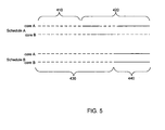
FIG. 5 , shown is a timing diagram of scheduling tasks to multiple cores of a package according to a conventional OS scheduling algorithm and according to an embodiment of the present invention. As shown inFIG. 5 , assume a first core A and a second core B are present in a processor package. Schedule A corresponds to a conventional scheduling. At aninitial time duration 410 of an activity interval, which may correspond to 500µs, both cores may be in an idle state (represented by a dashed line) and thus the package may be placed into the package C1 state. That is, although both cores are idle, because tasks are scheduled onto both cores in the near future, the latency needed to enter into a greater low power state exceeds its benefit. Thus, the package is placed only into the package C1 state. Then shown beginning attime 420, the package is transitioned to the active C0 state, as from that time forward at least one of the two cores is busy (the active state is represented by the solid lines) executing tasks or other operations. - In contrast, with reference to schedule B, scheduled in accordance with an embodiment of the present invention, a delay period corresponding to
time duration 430 is provided at a beginning of the operation interval. Because of the extended duration of thisdelay period 430, which may be 425µs, the package may be placed in a deeper low power state, e.g., a package C3 state (or even deeper C-state), thus enabling greatly enhanced power savings, on the order of approximately 60% more than that of schedule A. At the conclusion of thisdelay period 430, the package is placed into the active state and thus for the remaining duration of the operation interval, the package is in the package C0 state fortime duration 440. While not shown inFIG. 5 , understand that individual cores may enter into core low power states (e.g., core C-states) during this active period. For example, all cores may be in the active state at a beginning of the active period, and as tasks and break events are completed, individual cores can be placed into a core low power state. Thus in this particular example, where a 15% load level exists, no performance impact occurs, while achieving 60% greater power savings than a conventional scheduling. Embodiments thus enable improved processor power consumption and no performance impact. - For purposes of example, Table 3 below shows package C-states and their descriptions, along with the estimated power consumption in these states, with reference to an example processor having a thermal design power (TDP) of 130 watts (W). Of course it is to be understood that this is an example only, and embodiments are not limited in this regard.
Table 3 Description Estimated power consumption Package
(Pkg) C0All uncore and core logics active 130W Pkg C1 All cores inactive, package (pkg) clockgated 28W Pkg C3 Pkg C1 state + all external links to long-latency idle states + put memory in short-latency inactive state 18W Pkg C6 Pkg C3 state + reduced voltage for powerplane (only very low retention voltage remains) + put memory in long-latency inactive state 10W Pkg C7 Pkg C6 state + last level cache (LLC) shrunk 5W - While described herein as OS-based scheduling, embodiments are not limited in this regard. That is, in other implementations, software, firmware or hardware may be adapted on a package basis or at another location within a system, such as a power management unit (PMU) to enable dynamic rescheduling of tasks within an operating interval such that extended, continuous idle periods within each operating interval may be realized, enhancing the ability to enter into extended and deeper low power states on a package basis. Furthermore, while shown in
FIG. 5 as providing the delay period at the beginning of an operation interval, the scope of the present invention is not limited in this regard and in other implementations, processing may be performed up front, followed by the delay period. - Embodiments may be implemented in many different system types. Referring now to
FIG. 6 , shown is a block diagram of a system in accordance with an embodiment of the present invention. As shown inFIG. 6 ,multiprocessor system 500 is a point-to-point interconnect system, and includes afirst processor 570 and asecond processor 580 coupled via a point-to-point interconnect 550. As shown inFIG. 6 , each ofprocessors processor cores processor cores processor - Still referring to
FIG. 6 ,first processor 570 further includes a memory controller hub (MCH) 572 and point-to-point (P-P) interfaces 576 and 578. Similarly,second processor 580 includes aMCH 582 andP-P interfaces FIG. 2 , MCH's 572 and 582 couple the processors to respective memories, namely amemory 532 and amemory 534, which may be portions of main memory (e.g., a dynamic random access memory (DRAM)) locally attached to the respective processors.First processor 570 andsecond processor 580 may be coupled to achipset 590 via P-P interconnects 552 and 554, respectively. As shown inFIG. 6 ,chipset 590 includesP-P interfaces - Furthermore,
chipset 590 includes aninterface 592 tocouple chipset 590 with a highperformance graphics engine 538, by aP-P interconnect 539. In turn,chipset 590 may be coupled to afirst bus 516 via aninterface 596. As shown inFIG. 6 , various I/O devices 514 may be coupled tofirst bus 516, along with a bus bridge 518 which couplesfirst bus 516 to asecond bus 520. Various devices may be coupled tosecond bus 520 including, for example, a keyboard/mouse 522,communication devices 526 and adata storage unit 528 such as a disk drive or other mass storage device which may includecode 530, in one embodiment. Further, an audio I/O 524 may be coupled tosecond bus 520. - Embodiments may be implemented in code and may be stored on a storage medium having stored thereon instructions which can be used to program a system to perform the instructions. The storage medium may include, but is not limited to, any type of disk including floppy disks, optical disks, compact disk read-only memories (CD-ROMs), compact disk rewritables (CD-RWs), and magneto-optical disks, semiconductor devices such as read-only memories (ROMs), random access memories (RAMs) such as dynamic random access memories (DRAMs), static random access memories (SRAMs), erasable programmable read-only memories (EPROMs), flash memories, electrically erasable programmable read-only memories (EEPROMs), magnetic or optical cards, or any other type of media suitable for storing electronic instructions.
- While the present invention has been described with respect to a limited number of embodiments, those skilled in the art will appreciate numerous modifications and variations therefrom. It is intended that the appended claims cover all such modifications and variations as fall within the true spirit and scope of this present invention.
Claims (14)
- A method comprising:receiving prediction information regarding utilization of a plurality of cores of a processor package for a next operation interval;setting a delay period for the processor package during the next operation interval based on the prediction information; andcausing the processor package to enter into a package low power state for the delay period and thereafter causing the processor package to enter into a package active state for an active period of the next operation interval, the delay period extending from a beginning of the next operation interval to a beginning of the active period.
- The method of claim 1, further comprising initializing a timer of the processor package to a length of the delay period, and initiating the active period when the timer times out.
- The method of claim 2, further comprising receiving the prediction information and setting the delay period in an operating system (OS) and transmitting a value of the delay period from the OS to the processor package to initialize the timer.
- The method of claim 1, wherein the active period corresponds to a duration sufficient to execute tasks and break events scheduled to a core of the plurality of cores having a greatest predicted utilization, and the delay period corresponds to NOI x (100% - Umax), where NOI corresponds to the next operation interval, and Umax is the greatest predicted utilization.
- The method of claim 4, further comprising:fetching the break events from a buffer external to the processor package after the beginning of the active period; andservicing the break events and thereafter servicing the tasks, wherein the break events and the tasks are serviced according to an original scheduling delayed by the delay period.
- A system comprising:a processor package including a plurality of cores and at least one timer, wherein the processor package is to be in a package low power state for a first portion of an operation interval and in a package active state for a second portion of the operation interval, wherein operations scheduled for the plurality of cores during the first portion are delayed until the second portion; anda memory coupled to the processor package.
- The system of claim 6, further comprising:a monitor coupled to the processor package to receive utilization information for the plurality of cores for a current interval;a predictor coupled to the monitor to predict a utilization rate for each of the plurality of cores for the operation interval based on the utilization information; anda scheduler coupled to the predictor to receive the utilization rates and to determine a length of the first portion of the operation interval based on at least one of the utilization rates.
- The system of claim 6, wherein the processor package is to enter into the package active state during the second portion of the operation interval, wherein the second portion corresponds to a duration sufficient to execute tasks and break events scheduled to a core of the plurality of cores having a greatest predicted utilization rate.
- The system of claim 8, wherein the first period corresponds to:OI x (100% - Umax), where OI corresponds to the operation interval, and Umax is the greatest predicted utilization rate.
- The system of claim 7, wherein the scheduler is to reschedule an original timing for a plurality of tasks from within the first portion to within the second portion, wherein the processor package is to execute the plurality of tasks in the second portion according to the original timing.
- An article comprising a machine-accessible medium including instructions that when executed cause a system to:determine a delay period corresponding to a difference between a length of a next operation interval and a length of time to service operations in the next operation interval scheduled to a core of a multicore processor having a highest predicted utilization rate for the next operation interval; andcontrol entry of the multicore processor into a package low power state at a beginning of the next operation interval and exit of the multicore processor from the package low power state to a package active state at a conclusion of the delay period.
- The article of claim 11, further comprising instructions that enable the system to receive a prediction value corresponding to a prediction for the core and determine the delay period in an operating system (OS) and transmit a value of the delay period from the OS to the multicore processor to initialize a timer of the multicore processor.
- The article of claim 11, wherein the delay period corresponds to NOI x (100% - Umax), where NOI corresponds to the next operation interval, and Umax is the highest predicted utilization rate.
- The article of claim 13, wherein the instructions enable the system to fetch break events from a buffer external to the multicore processor after the delay period and service the break events and thereafter service tasks scheduled to the multicore processor, wherein the break events and the tasks are serviced according to an original scheduling delayed by the delay period.
Applications Claiming Priority (1)
| Application Number | Priority Date | Filing Date | Title |
|---|---|---|---|
| US12/001,186 US20090150696A1 (en) | 2007-12-10 | 2007-12-10 | Transitioning a processor package to a low power state |
Publications (3)
| Publication Number | Publication Date |
|---|---|
| EP2073097A2 true EP2073097A2 (en) | 2009-06-24 |
| EP2073097A3 EP2073097A3 (en) | 2009-07-29 |
| EP2073097B1 EP2073097B1 (en) | 2017-01-25 |
Family
ID=40467257
Family Applications (1)
| Application Number | Title | Priority Date | Filing Date |
|---|---|---|---|
| EP08253932.1A Active EP2073097B1 (en) | 2007-12-10 | 2008-12-09 | Transitioning a processor package to a low power state |
Country Status (3)
| Country | Link |
|---|---|
| US (1) | US20090150696A1 (en) |
| EP (1) | EP2073097B1 (en) |
| CN (1) | CN101458558B (en) |
Cited By (6)
| Publication number | Priority date | Publication date | Assignee | Title |
|---|---|---|---|---|
| EP2846217A1 (en) * | 2013-06-26 | 2015-03-11 | Intel Corporation | Controlling reduced power states using platform latency tolerance |
| EP2887182A1 (en) * | 2013-12-17 | 2015-06-24 | Intel IP Corporation | Rescheduling workloads to enforce and maintain a duty cycle |
| WO2016022308A3 (en) * | 2014-08-05 | 2016-04-14 | Qualcomm Incorporated | Directed event signaling for multiprocessor systems |
| WO2017136099A3 (en) * | 2016-02-05 | 2018-02-22 | Qualcomm Incorporated | Forced idling of memory subsystems |
| EP2550576B1 (en) * | 2010-03-23 | 2020-01-01 | Sony Corporation | Reducing power consumption by masking a process from a processor performance management system |
| EP4160358A3 (en) * | 2021-10-01 | 2023-07-19 | Samsung Electronics Co., Ltd. | System on chip and application processor |
Families Citing this family (160)
| Publication number | Priority date | Publication date | Assignee | Title |
|---|---|---|---|---|
| US8799687B2 (en) | 2005-12-30 | 2014-08-05 | Intel Corporation | Method, apparatus, and system for energy efficiency and energy conservation including optimizing C-state selection under variable wakeup rates |
| US8024590B2 (en) * | 2007-12-10 | 2011-09-20 | Intel Corporation | Predicting future power level states for processor cores |
| US8615647B2 (en) | 2008-02-29 | 2013-12-24 | Intel Corporation | Migrating execution of thread between cores of different instruction set architecture in multi-core processor and transitioning each core to respective on / off power state |
| US8156362B2 (en) * | 2008-03-11 | 2012-04-10 | Globalfoundries Inc. | Hardware monitoring and decision making for transitioning in and out of low-power state |
| US8028185B2 (en) * | 2008-03-11 | 2011-09-27 | Globalfoundries Inc. | Protocol for transitioning in and out of zero-power state |
| US8112648B2 (en) * | 2008-03-11 | 2012-02-07 | Globalfoundries Inc. | Enhanced control of CPU parking and thread rescheduling for maximizing the benefits of low-power state |
| US8112647B2 (en) * | 2008-08-27 | 2012-02-07 | Globalfoundries Inc. | Protocol for power state determination and demotion |
| US9052904B1 (en) * | 2008-09-05 | 2015-06-09 | Symantec Corporation | System and method for determining whether to reschedule malware scans based on power-availability information for a power grid and power-usage information for the scans |
| US8612998B2 (en) * | 2010-09-23 | 2013-12-17 | Intel Corporation | Coordinating device and application break events for platform power saving |
| US8566628B2 (en) * | 2009-05-06 | 2013-10-22 | Advanced Micro Devices, Inc. | North-bridge to south-bridge protocol for placing processor in low power state |
| US8527796B2 (en) | 2009-08-24 | 2013-09-03 | Intel Corporation | Providing adaptive frequency control for a processor using utilization information |
| US20110112798A1 (en) * | 2009-11-06 | 2011-05-12 | Alexander Branover | Controlling performance/power by frequency control of the responding node |
| US9128705B2 (en) | 2009-12-16 | 2015-09-08 | Qualcomm Incorporated | System and method for controlling central processing unit power with reduced frequency oscillations |
| US9104411B2 (en) | 2009-12-16 | 2015-08-11 | Qualcomm Incorporated | System and method for controlling central processing unit power with guaranteed transient deadlines |
| US9176572B2 (en) | 2009-12-16 | 2015-11-03 | Qualcomm Incorporated | System and method for controlling central processing unit power with guaranteed transient deadlines |
| US8689037B2 (en) * | 2009-12-16 | 2014-04-01 | Qualcomm Incorporated | System and method for asynchronously and independently controlling core clocks in a multicore central processing unit |
| US20110145559A1 (en) * | 2009-12-16 | 2011-06-16 | Thomson Steven S | System and method for controlling central processing unit power with guaranteed steady state deadlines |
| US8650426B2 (en) | 2009-12-16 | 2014-02-11 | Qualcomm Incorporated | System and method for controlling central processing unit power in a virtualized system |
| US9563250B2 (en) * | 2009-12-16 | 2017-02-07 | Qualcomm Incorporated | System and method for controlling central processing unit power based on inferred workload parallelism |
| US8909962B2 (en) | 2009-12-16 | 2014-12-09 | Qualcomm Incorporated | System and method for controlling central processing unit power with guaranteed transient deadlines |
| US8775830B2 (en) | 2009-12-16 | 2014-07-08 | Qualcomm Incorporated | System and method for dynamically controlling a plurality of cores in a multicore central processing unit based on temperature |
| US8464035B2 (en) * | 2009-12-18 | 2013-06-11 | Intel Corporation | Instruction for enabling a processor wait state |
| US8887171B2 (en) * | 2009-12-28 | 2014-11-11 | Intel Corporation | Mechanisms to avoid inefficient core hopping and provide hardware assisted low-power state selection |
| JP5438212B2 (en) * | 2010-04-30 | 2014-03-12 | 富士通株式会社 | Information processing apparatus and power consumption management program |
| US20110289332A1 (en) * | 2010-05-24 | 2011-11-24 | Advanced Micro Devices, Inc. | Method and apparatus for power management in a multi-processor system |
| US8504854B2 (en) | 2010-06-21 | 2013-08-06 | Advanced Micro Devices, Inc. | Managing multiple operating points for stable virtual frequencies |
| US8943334B2 (en) | 2010-09-23 | 2015-01-27 | Intel Corporation | Providing per core voltage and frequency control |
| US9026829B2 (en) | 2010-09-25 | 2015-05-05 | Intel Corporation | Package level power state optimization |
| US9261949B2 (en) | 2010-10-29 | 2016-02-16 | Advanced Micro Devices, Inc. | Method for adaptive performance optimization of the soc |
| US8380860B2 (en) * | 2010-11-09 | 2013-02-19 | International Business Machines Corporation | Reducing carbon footprint and providing power savings in session initiated protocol conferencing |
| US20120159123A1 (en) * | 2010-12-17 | 2012-06-21 | Advanced Micro Devices, Inc. | Cstate boost method and apparatus |
| US9069555B2 (en) | 2011-03-21 | 2015-06-30 | Intel Corporation | Managing power consumption in a multi-core processor |
| US8793515B2 (en) | 2011-06-27 | 2014-07-29 | Intel Corporation | Increasing power efficiency of turbo mode operation in a processor |
| US8769316B2 (en) | 2011-09-06 | 2014-07-01 | Intel Corporation | Dynamically allocating a power budget over multiple domains of a processor |
| US8688883B2 (en) | 2011-09-08 | 2014-04-01 | Intel Corporation | Increasing turbo mode residency of a processor |
| US8914650B2 (en) | 2011-09-28 | 2014-12-16 | Intel Corporation | Dynamically adjusting power of non-core processor circuitry including buffer circuitry |
| US9074947B2 (en) | 2011-09-28 | 2015-07-07 | Intel Corporation | Estimating temperature of a processor core in a low power state without thermal sensor information |
| US8954770B2 (en) | 2011-09-28 | 2015-02-10 | Intel Corporation | Controlling temperature of multiple domains of a multi-domain processor using a cross domain margin |
| WO2013057769A1 (en) * | 2011-10-20 | 2013-04-25 | 富士通株式会社 | Information processing device, control method for information processing device and control program |
| US9026815B2 (en) | 2011-10-27 | 2015-05-05 | Intel Corporation | Controlling operating frequency of a core domain via a non-core domain of a multi-domain processor |
| US8832478B2 (en) | 2011-10-27 | 2014-09-09 | Intel Corporation | Enabling a non-core domain to control memory bandwidth in a processor |
| US9158693B2 (en) | 2011-10-31 | 2015-10-13 | Intel Corporation | Dynamically controlling cache size to maximize energy efficiency |
| US8943340B2 (en) | 2011-10-31 | 2015-01-27 | Intel Corporation | Controlling a turbo mode frequency of a processor |
| WO2013077890A1 (en) * | 2011-11-22 | 2013-05-30 | Intel Corporation | Collaborative processor and system performance and power management |
| CN103218032B (en) * | 2011-11-29 | 2017-07-14 | 英特尔公司 | Utilize the power management of relative energy break-even time |
| US8862909B2 (en) | 2011-12-02 | 2014-10-14 | Advanced Micro Devices, Inc. | System and method for determining a power estimate for an I/O controller based on monitored activity levels and adjusting power limit of processing units by comparing the power estimate with an assigned power limit for the I/O controller |
| US8972763B2 (en) | 2011-12-05 | 2015-03-03 | Intel Corporation | Method, apparatus, and system for energy efficiency and energy conservation including determining an optimal power state of the apparatus based on residency time of non-core domains in a power saving state |
| US9239611B2 (en) | 2011-12-05 | 2016-01-19 | Intel Corporation | Method, apparatus, and system for energy efficiency and energy conservation including balancing power among multi-frequency domains of a processor based on efficiency rating scheme |
| US8924758B2 (en) | 2011-12-13 | 2014-12-30 | Advanced Micro Devices, Inc. | Method for SOC performance and power optimization |
| US9052901B2 (en) | 2011-12-14 | 2015-06-09 | Intel Corporation | Method, apparatus, and system for energy efficiency and energy conservation including configurable maximum processor current |
| US9372524B2 (en) | 2011-12-15 | 2016-06-21 | Intel Corporation | Dynamically modifying a power/performance tradeoff based on processor utilization |
| US9098261B2 (en) | 2011-12-15 | 2015-08-04 | Intel Corporation | User level control of power management policies |
| WO2013137860A1 (en) | 2012-03-13 | 2013-09-19 | Intel Corporation | Dynamically computing an electrical design point (edp) for a multicore processor |
| WO2013137859A1 (en) | 2012-03-13 | 2013-09-19 | Intel Corporation | Providing energy efficient turbo operation of a processor |
| US9323316B2 (en) | 2012-03-13 | 2016-04-26 | Intel Corporation | Dynamically controlling interconnect frequency in a processor |
| CN104204825B (en) | 2012-03-30 | 2017-06-27 | 英特尔公司 | Power consumption in dynamic measurement processor |
| WO2013147914A1 (en) * | 2012-03-31 | 2013-10-03 | Intel Corporation | Controlling power management in micro-servers |
| US10185566B2 (en) | 2012-04-27 | 2019-01-22 | Intel Corporation | Migrating tasks between asymmetric computing elements of a multi-core processor |
| US8984313B2 (en) | 2012-08-31 | 2015-03-17 | Intel Corporation | Configuring power management functionality in a processor including a plurality of cores by utilizing a register to store a power domain indicator |
| US9063727B2 (en) | 2012-08-31 | 2015-06-23 | Intel Corporation | Performing cross-domain thermal control in a processor |
| US9032258B2 (en) * | 2012-09-14 | 2015-05-12 | Infineon Technologies Ag | Safety system challenge-and-response using modified watchdog timer |
| US9342122B2 (en) | 2012-09-17 | 2016-05-17 | Intel Corporation | Distributing power to heterogeneous compute elements of a processor |
| US9423858B2 (en) | 2012-09-27 | 2016-08-23 | Intel Corporation | Sharing power between domains in a processor package using encoded power consumption information from a second domain to calculate an available power budget for a first domain |
| US9575543B2 (en) | 2012-11-27 | 2017-02-21 | Intel Corporation | Providing an inter-arrival access timer in a processor |
| US9442557B2 (en) * | 2012-11-28 | 2016-09-13 | Advanced Micro Devices, Inc. | Using a linear prediction to configure an idle state of an entity in a computing device |
| US9183144B2 (en) | 2012-12-14 | 2015-11-10 | Intel Corporation | Power gating a portion of a cache memory |
| US9405351B2 (en) | 2012-12-17 | 2016-08-02 | Intel Corporation | Performing frequency coordination in a multiprocessor system |
| US9292468B2 (en) | 2012-12-17 | 2016-03-22 | Intel Corporation | Performing frequency coordination in a multiprocessor system based on response timing optimization |
| US10133577B2 (en) | 2012-12-19 | 2018-11-20 | Intel Corporation | Vector mask driven clock gating for power efficiency of a processor |
| US9075556B2 (en) | 2012-12-21 | 2015-07-07 | Intel Corporation | Controlling configurable peak performance limits of a processor |
| US9235252B2 (en) | 2012-12-21 | 2016-01-12 | Intel Corporation | Dynamic balancing of power across a plurality of processor domains according to power policy control bias |
| US9213390B2 (en) * | 2012-12-28 | 2015-12-15 | Intel Corporation | Periodic activity alignment |
| US9164565B2 (en) | 2012-12-28 | 2015-10-20 | Intel Corporation | Apparatus and method to manage energy usage of a processor |
| US9081577B2 (en) | 2012-12-28 | 2015-07-14 | Intel Corporation | Independent control of processor core retention states |
| US9208113B2 (en) * | 2013-01-15 | 2015-12-08 | Apple Inc. | Deferred inter-processor interrupts |
| US9329671B2 (en) * | 2013-01-29 | 2016-05-03 | Nvidia Corporation | Power-efficient inter processor communication scheduling |
| US9335803B2 (en) | 2013-02-15 | 2016-05-10 | Intel Corporation | Calculating a dynamically changeable maximum operating voltage value for a processor based on a different polynomial equation using a set of coefficient values and a number of current active cores |
| US9367114B2 (en) | 2013-03-11 | 2016-06-14 | Intel Corporation | Controlling operating voltage of a processor |
| US9354694B2 (en) * | 2013-03-14 | 2016-05-31 | Intel Corporation | Controlling processor consumption using on-off keying having a maximum off time |
| US9348400B2 (en) * | 2013-04-15 | 2016-05-24 | Broadcom Corporation | Method for saving power on multi-channel devices |
| US9395784B2 (en) | 2013-04-25 | 2016-07-19 | Intel Corporation | Independently controlling frequency of plurality of power domains in a processor system |
| US9377841B2 (en) | 2013-05-08 | 2016-06-28 | Intel Corporation | Adaptively limiting a maximum operating frequency in a multicore processor |
| US9766685B2 (en) * | 2013-05-15 | 2017-09-19 | Intel Corporation | Controlling power consumption of a processor using interrupt-mediated on-off keying |
| US9823719B2 (en) | 2013-05-31 | 2017-11-21 | Intel Corporation | Controlling power delivery to a processor via a bypass |
| US9471088B2 (en) | 2013-06-25 | 2016-10-18 | Intel Corporation | Restricting clock signal delivery in a processor |
| US9348401B2 (en) | 2013-06-25 | 2016-05-24 | Intel Corporation | Mapping a performance request to an operating frequency in a processor |
| US9348407B2 (en) | 2013-06-27 | 2016-05-24 | Intel Corporation | Method and apparatus for atomic frequency and voltage changes |
| CN105247442B (en) * | 2013-06-28 | 2018-06-08 | 英特尔公司 | For managing the technology and system of the activity in multi-part platform |
| US9377836B2 (en) | 2013-07-26 | 2016-06-28 | Intel Corporation | Restricting clock signal delivery based on activity in a processor |
| US9495001B2 (en) | 2013-08-21 | 2016-11-15 | Intel Corporation | Forcing core low power states in a processor |
| US10386900B2 (en) | 2013-09-24 | 2019-08-20 | Intel Corporation | Thread aware power management |
| US9405345B2 (en) | 2013-09-27 | 2016-08-02 | Intel Corporation | Constraining processor operation based on power envelope information |
| US9594560B2 (en) | 2013-09-27 | 2017-03-14 | Intel Corporation | Estimating scalability value for a specific domain of a multicore processor based on active state residency of the domain, stall duration of the domain, memory bandwidth of the domain, and a plurality of coefficients based on a workload to execute on the domain |
| US9459689B2 (en) | 2013-12-23 | 2016-10-04 | Intel Corporation | Dyanamically adapting a voltage of a clock generation circuit |
| US9851777B2 (en) | 2014-01-02 | 2017-12-26 | Advanced Micro Devices, Inc. | Power gating based on cache dirtiness |
| US9720487B2 (en) | 2014-01-10 | 2017-08-01 | Advanced Micro Devices, Inc. | Predicting power management state duration on a per-process basis and modifying cache size based on the predicted duration |
| US9323525B2 (en) | 2014-02-26 | 2016-04-26 | Intel Corporation | Monitoring vector lane duty cycle for dynamic optimization |
| US10108454B2 (en) | 2014-03-21 | 2018-10-23 | Intel Corporation | Managing dynamic capacitance using code scheduling |
| US9665153B2 (en) | 2014-03-21 | 2017-05-30 | Intel Corporation | Selecting a low power state based on cache flush latency determination |
| US10417149B2 (en) | 2014-06-06 | 2019-09-17 | Intel Corporation | Self-aligning a processor duty cycle with interrupts |
| US9760158B2 (en) * | 2014-06-06 | 2017-09-12 | Intel Corporation | Forcing a processor into a low power state |
| US9507410B2 (en) * | 2014-06-20 | 2016-11-29 | Advanced Micro Devices, Inc. | Decoupled selective implementation of entry and exit prediction for power gating processor components |
| US9513689B2 (en) | 2014-06-30 | 2016-12-06 | Intel Corporation | Controlling processor performance scaling based on context |
| US9606602B2 (en) | 2014-06-30 | 2017-03-28 | Intel Corporation | Method and apparatus to prevent voltage droop in a computer |
| US10114448B2 (en) | 2014-07-02 | 2018-10-30 | Intel Corporation | Autonomous C-state algorithm and computational engine alignment for improved processor power efficiency |
| US9575537B2 (en) | 2014-07-25 | 2017-02-21 | Intel Corporation | Adaptive algorithm for thermal throttling of multi-core processors with non-homogeneous performance states |
| US9760136B2 (en) | 2014-08-15 | 2017-09-12 | Intel Corporation | Controlling temperature of a system memory |
| US9671853B2 (en) | 2014-09-12 | 2017-06-06 | Intel Corporation | Processor operating by selecting smaller of requested frequency and an energy performance gain (EPG) frequency |
| US10339023B2 (en) | 2014-09-25 | 2019-07-02 | Intel Corporation | Cache-aware adaptive thread scheduling and migration |
| US9977477B2 (en) | 2014-09-26 | 2018-05-22 | Intel Corporation | Adapting operating parameters of an input/output (IO) interface circuit of a processor |
| US9684360B2 (en) | 2014-10-30 | 2017-06-20 | Intel Corporation | Dynamically controlling power management of an on-die memory of a processor |
| US9703358B2 (en) | 2014-11-24 | 2017-07-11 | Intel Corporation | Controlling turbo mode frequency operation in a processor |
| US20160147280A1 (en) | 2014-11-26 | 2016-05-26 | Tessil Thomas | Controlling average power limits of a processor |
| US10048744B2 (en) | 2014-11-26 | 2018-08-14 | Intel Corporation | Apparatus and method for thermal management in a multi-chip package |
| US9710043B2 (en) | 2014-11-26 | 2017-07-18 | Intel Corporation | Controlling a guaranteed frequency of a processor |
| US10877530B2 (en) | 2014-12-23 | 2020-12-29 | Intel Corporation | Apparatus and method to provide a thermal parameter report for a multi-chip package |
| US20160224098A1 (en) | 2015-01-30 | 2016-08-04 | Alexander Gendler | Communicating via a mailbox interface of a processor |
| US9639134B2 (en) | 2015-02-05 | 2017-05-02 | Intel Corporation | Method and apparatus to provide telemetry data to a power controller of a processor |
| US10234930B2 (en) | 2015-02-13 | 2019-03-19 | Intel Corporation | Performing power management in a multicore processor |
| US9910481B2 (en) | 2015-02-13 | 2018-03-06 | Intel Corporation | Performing power management in a multicore processor |
| US9874922B2 (en) | 2015-02-17 | 2018-01-23 | Intel Corporation | Performing dynamic power control of platform devices |
| US9842082B2 (en) | 2015-02-27 | 2017-12-12 | Intel Corporation | Dynamically updating logical identifiers of cores of a processor |
| US9710054B2 (en) | 2015-02-28 | 2017-07-18 | Intel Corporation | Programmable power management agent |
| US9760160B2 (en) | 2015-05-27 | 2017-09-12 | Intel Corporation | Controlling performance states of processing engines of a processor |
| US9710041B2 (en) | 2015-07-29 | 2017-07-18 | Intel Corporation | Masking a power state of a core of a processor |
| US10001822B2 (en) | 2015-09-22 | 2018-06-19 | Intel Corporation | Integrating a power arbiter in a processor |
| US9983644B2 (en) | 2015-11-10 | 2018-05-29 | Intel Corporation | Dynamically updating at least one power management operational parameter pertaining to a turbo mode of a processor for increased performance |
| US9892058B2 (en) | 2015-12-16 | 2018-02-13 | Advanced Micro Devices, Inc. | Centrally managed unified shared virtual address space |
| US9910470B2 (en) | 2015-12-16 | 2018-03-06 | Intel Corporation | Controlling telemetry data communication in a processor |
| US10146286B2 (en) | 2016-01-14 | 2018-12-04 | Intel Corporation | Dynamically updating a power management policy of a processor |
| CN107132903B (en) * | 2016-02-29 | 2020-11-13 | 中兴通讯股份有限公司 | Energy-saving management implementation method, device and network equipment |
| US10289188B2 (en) * | 2016-06-21 | 2019-05-14 | Intel Corporation | Processor having concurrent core and fabric exit from a low power state |
| US10324519B2 (en) | 2016-06-23 | 2019-06-18 | Intel Corporation | Controlling forced idle state operation in a processor |
| US10281975B2 (en) | 2016-06-23 | 2019-05-07 | Intel Corporation | Processor having accelerated user responsiveness in constrained environment |
| US10379596B2 (en) | 2016-08-03 | 2019-08-13 | Intel Corporation | Providing an interface for demotion control information in a processor |
| US10379904B2 (en) | 2016-08-31 | 2019-08-13 | Intel Corporation | Controlling a performance state of a processor using a combination of package and thread hint information |
| US10423206B2 (en) | 2016-08-31 | 2019-09-24 | Intel Corporation | Processor to pre-empt voltage ramps for exit latency reductions |
| US10234920B2 (en) | 2016-08-31 | 2019-03-19 | Intel Corporation | Controlling current consumption of a processor based at least in part on platform capacitance |
| US10168758B2 (en) | 2016-09-29 | 2019-01-01 | Intel Corporation | Techniques to enable communication between a processor and voltage regulator |
| US10429919B2 (en) | 2017-06-28 | 2019-10-01 | Intel Corporation | System, apparatus and method for loose lock-step redundancy power management |
| US10970118B2 (en) | 2017-08-02 | 2021-04-06 | Advanced Micro Devices, Inc. | Shareable FPGA compute engine |
| WO2019040054A1 (en) | 2017-08-23 | 2019-02-28 | Intel Corporation | System, apparatus and method for adaptive operating voltage in a field programmable gate array (fpga) |
| US20190146567A1 (en) * | 2017-11-10 | 2019-05-16 | Advanced Micro Devices, Inc. | Processor throttling based on accumulated combined current measurements |
| US10620266B2 (en) | 2017-11-29 | 2020-04-14 | Intel Corporation | System, apparatus and method for in-field self testing in a diagnostic sleep state |
| US10620682B2 (en) | 2017-12-21 | 2020-04-14 | Intel Corporation | System, apparatus and method for processor-external override of hardware performance state control of a processor |
| US10620969B2 (en) | 2018-03-27 | 2020-04-14 | Intel Corporation | System, apparatus and method for providing hardware feedback information in a processor |
| US10739844B2 (en) | 2018-05-02 | 2020-08-11 | Intel Corporation | System, apparatus and method for optimized throttling of a processor |
| US10955899B2 (en) | 2018-06-20 | 2021-03-23 | Intel Corporation | System, apparatus and method for responsive autonomous hardware performance state control of a processor |
| US10976801B2 (en) | 2018-09-20 | 2021-04-13 | Intel Corporation | System, apparatus and method for power budget distribution for a plurality of virtual machines to execute on a processor |
| US10860083B2 (en) | 2018-09-26 | 2020-12-08 | Intel Corporation | System, apparatus and method for collective power control of multiple intellectual property agents and a shared power rail |
| US11656676B2 (en) | 2018-12-12 | 2023-05-23 | Intel Corporation | System, apparatus and method for dynamic thermal distribution of a system on chip |
| KR20200101210A (en) * | 2019-02-19 | 2020-08-27 | 삼성전자주식회사 | Electronic device and method for determining operating frequency of processor |
| US11256657B2 (en) | 2019-03-26 | 2022-02-22 | Intel Corporation | System, apparatus and method for adaptive interconnect routing |
| US11442529B2 (en) | 2019-05-15 | 2022-09-13 | Intel Corporation | System, apparatus and method for dynamically controlling current consumption of processing circuits of a processor |
| US11422812B2 (en) | 2019-06-25 | 2022-08-23 | Advanced Micro Devices, Inc. | Method and apparatus for efficient programmable instructions in computer systems |
| US11698812B2 (en) | 2019-08-29 | 2023-07-11 | Intel Corporation | System, apparatus and method for providing hardware state feedback to an operating system in a heterogeneous processor |
| US11366506B2 (en) | 2019-11-22 | 2022-06-21 | Intel Corporation | System, apparatus and method for globally aware reactive local power control in a processor |
| US11132201B2 (en) | 2019-12-23 | 2021-09-28 | Intel Corporation | System, apparatus and method for dynamic pipeline stage control of data path dominant circuitry of an integrated circuit |
| CN112416368B (en) * | 2020-11-25 | 2024-01-16 | 中国科学技术大学先进技术研究院 | Cache deployment and task scheduling method, terminal and computer readable storage medium |
| US11921564B2 (en) | 2022-02-28 | 2024-03-05 | Intel Corporation | Saving and restoring configuration and status information with reduced latency |
Citations (7)
| Publication number | Priority date | Publication date | Assignee | Title |
|---|---|---|---|---|
| US20010044909A1 (en) * | 2000-05-15 | 2001-11-22 | Lg Electronics Inc. | Method and apparatus for adjusting clock throttle rate based on usage of CPU |
| EP1282030A1 (en) * | 2000-05-08 | 2003-02-05 | Mitsubishi Denki Kabushiki Kaisha | Computer system and computer-readable recording medium |
| US20040064752A1 (en) * | 2002-09-30 | 2004-04-01 | Kazachinsky Itamar S. | Method and apparatus for reducing clock frequency during low workload periods |
| US20040139356A1 (en) * | 2003-01-10 | 2004-07-15 | Kenneth Ma | Method and apparatus for improving bus master performance |
| US20050022038A1 (en) * | 2003-07-23 | 2005-01-27 | Kaushik Shivnandan D. | Determining target operating frequencies for a multiprocessor system |
| US20050033881A1 (en) * | 2003-07-08 | 2005-02-10 | Benq Corporation | Method and apparatus for multi-interrupt controller for reducing hardware interrupts to DSP |
| US20070156992A1 (en) * | 2005-12-30 | 2007-07-05 | Intel Corporation | Method and system for optimizing latency of dynamic memory sizing |
Family Cites Families (29)
| Publication number | Priority date | Publication date | Assignee | Title |
|---|---|---|---|---|
| US5163153A (en) * | 1989-06-12 | 1992-11-10 | Grid Systems Corporation | Low-power, standby mode computer |
| US5522087A (en) * | 1994-03-22 | 1996-05-28 | Verifone Inc. | System for selectively operating in different modes depending upon receiving signal from a host computer within a time window upon power up |
| US5590341A (en) * | 1994-09-30 | 1996-12-31 | Intel Corporation | Method and apparatus for reducing power consumption in a computer system using ready delay |
| US5621250A (en) * | 1995-07-31 | 1997-04-15 | Ford Motor Company | Wake-up interface and method for awakening an automotive electronics module |
| US5931950A (en) * | 1997-06-17 | 1999-08-03 | Pc-Tel, Inc. | Wake-up-on-ring power conservation for host signal processing communication system |
| US7010708B2 (en) * | 2002-05-15 | 2006-03-07 | Broadcom Corporation | Method and apparatus for adaptive CPU power management |
| US20030061383A1 (en) * | 2001-09-25 | 2003-03-27 | Zilka Anthony M. | Predicting processor inactivity for a controlled transition of power states |
| US6996728B2 (en) * | 2002-04-26 | 2006-02-07 | Hewlett-Packard Development Company, L.P. | Managing power consumption based on utilization statistics |
| US6898689B2 (en) * | 2002-11-15 | 2005-05-24 | Silicon Labs Cp, Inc. | Paging scheme for a microcontroller for extending available register space |
| US7043649B2 (en) * | 2002-11-20 | 2006-05-09 | Portalplayer, Inc. | System clock power management for chips with multiple processing modules |
| JP4061492B2 (en) * | 2003-02-10 | 2008-03-19 | ソニー株式会社 | Information processing apparatus and power consumption control method |
| US7093147B2 (en) * | 2003-04-25 | 2006-08-15 | Hewlett-Packard Development Company, L.P. | Dynamically selecting processor cores for overall power efficiency |
| US7272730B1 (en) * | 2003-07-31 | 2007-09-18 | Hewlett-Packard Development Company, L.P. | Application-driven method and apparatus for limiting power consumption in a processor-controlled hardware platform |
| US7903116B1 (en) * | 2003-10-27 | 2011-03-08 | Nvidia Corporation | Method, apparatus, and system for adaptive performance level management of a graphics system |
| US7451333B2 (en) * | 2004-09-03 | 2008-11-11 | Intel Corporation | Coordinating idle state transitions in multi-core processors |
| US9001801B2 (en) * | 2004-09-07 | 2015-04-07 | Broadcom Corporation | Method and system for low power mode management for complex Bluetooth devices |
| US7941585B2 (en) * | 2004-09-10 | 2011-05-10 | Cavium Networks, Inc. | Local scratchpad and data caching system |
| US8041967B2 (en) * | 2005-02-15 | 2011-10-18 | Hewlett-Packard Development Company, L.P. | System and method for controlling power to resources based on historical utilization data |
| US7454632B2 (en) * | 2005-06-16 | 2008-11-18 | Intel Corporation | Reducing computing system power through idle synchronization |
| US7430673B2 (en) * | 2005-06-30 | 2008-09-30 | Intel Corporation | Power management system for computing platform |
| US20070106827A1 (en) * | 2005-11-08 | 2007-05-10 | Boatright Bryan D | Centralized interrupt controller |
| US7437270B2 (en) * | 2006-03-30 | 2008-10-14 | Intel Corporation | Performance state management |
| US7529956B2 (en) * | 2006-07-17 | 2009-05-05 | Microsoft Corporation | Granular reduction in power consumption |
| US7930564B2 (en) * | 2006-07-31 | 2011-04-19 | Intel Corporation | System and method for controlling processor low power states |
| US7730340B2 (en) * | 2007-02-16 | 2010-06-01 | Intel Corporation | Method and apparatus for dynamic voltage and frequency scaling |
| US8024590B2 (en) * | 2007-12-10 | 2011-09-20 | Intel Corporation | Predicting future power level states for processor cores |
| US8442697B2 (en) * | 2007-12-18 | 2013-05-14 | Packet Digital | Method and apparatus for on-demand power management |
| US20110106282A1 (en) * | 2009-07-23 | 2011-05-05 | Corevalus Systems, Llc | Audio Processing Utilizing a Dedicated CPU Core and a Real Time OS |
| US8321705B2 (en) * | 2009-10-13 | 2012-11-27 | Advanced Micro Devices, Inc. | Dynamic table look-up based voltage regulator control |
-
2007
- 2007-12-10 US US12/001,186 patent/US20090150696A1/en not_active Abandoned
-
2008
- 2008-12-09 EP EP08253932.1A patent/EP2073097B1/en active Active
- 2008-12-10 CN CN2008101871625A patent/CN101458558B/en not_active Expired - Fee Related
Patent Citations (7)
| Publication number | Priority date | Publication date | Assignee | Title |
|---|---|---|---|---|
| EP1282030A1 (en) * | 2000-05-08 | 2003-02-05 | Mitsubishi Denki Kabushiki Kaisha | Computer system and computer-readable recording medium |
| US20010044909A1 (en) * | 2000-05-15 | 2001-11-22 | Lg Electronics Inc. | Method and apparatus for adjusting clock throttle rate based on usage of CPU |
| US20040064752A1 (en) * | 2002-09-30 | 2004-04-01 | Kazachinsky Itamar S. | Method and apparatus for reducing clock frequency during low workload periods |
| US20040139356A1 (en) * | 2003-01-10 | 2004-07-15 | Kenneth Ma | Method and apparatus for improving bus master performance |
| US20050033881A1 (en) * | 2003-07-08 | 2005-02-10 | Benq Corporation | Method and apparatus for multi-interrupt controller for reducing hardware interrupts to DSP |
| US20050022038A1 (en) * | 2003-07-23 | 2005-01-27 | Kaushik Shivnandan D. | Determining target operating frequencies for a multiprocessor system |
| US20070156992A1 (en) * | 2005-12-30 | 2007-07-05 | Intel Corporation | Method and system for optimizing latency of dynamic memory sizing |
Non-Patent Citations (3)
| Title |
|---|
| BENINI L ET AL: "System-level dynamic power management" LOW-POWER DESIGN, 1999. PROCEEDINGS. IEEE ALESSANDRO VOLTA MEMORIAL WO RKSHOP ON COMO, ITALY 4-5 MARCH 1999, LOS ALAMITOS, CA, USA,IEEE COMPUT. SOC, US, 4 March 1999 (1999-03-04), pages 23-31, XP010323924 ISBN: 978-0-7695-0019-5 * |
| JEJURIKAR R ET AL: "Dynamic slack reclamation with procrastination scheduling in real-time embedded systems" DESIGN AUTOMATION CONFERENCE, 2005. PROCEEDINGS. 42ND ANAHEIM, CA, USA 13-17 JUNE 2005, PISCATAWAY, NJ, USA,IEEE, US, 13 June 2005 (2005-06-13), pages 111-116, XP010837187 ISBN: 978-1-59593-058-3 * |
| JEJURIKAR R ET AL: "Leakage aware dynamic voltage scaling for real-time embedded systems" DESIGN AUTOMATION CONFERENCE, 2004. PROCEEDINGS. 41ST SAN DIEGO, CA, USA JUNE 7-11, 2004, PISCATAWAY, NJ, USA,IEEE, 7 June 2004 (2004-06-07), pages 275-280, XP010715660 ISBN: 978-1-5118-3828-3 * |
Cited By (12)
| Publication number | Priority date | Publication date | Assignee | Title |
|---|---|---|---|---|
| EP2550576B1 (en) * | 2010-03-23 | 2020-01-01 | Sony Corporation | Reducing power consumption by masking a process from a processor performance management system |
| EP2846217A1 (en) * | 2013-06-26 | 2015-03-11 | Intel Corporation | Controlling reduced power states using platform latency tolerance |
| US9195292B2 (en) | 2013-06-26 | 2015-11-24 | Intel Corporation | Controlling reduced power states using platform latency tolerance |
| US9541983B2 (en) | 2013-06-26 | 2017-01-10 | Intel Corporation | Controlling reduced power states using platform latency tolerance |
| EP2887182A1 (en) * | 2013-12-17 | 2015-06-24 | Intel IP Corporation | Rescheduling workloads to enforce and maintain a duty cycle |
| US9494998B2 (en) | 2013-12-17 | 2016-11-15 | Intel Corporation | Rescheduling workloads to enforce and maintain a duty cycle |
| WO2016022308A3 (en) * | 2014-08-05 | 2016-04-14 | Qualcomm Incorporated | Directed event signaling for multiprocessor systems |
| US9632569B2 (en) | 2014-08-05 | 2017-04-25 | Qualcomm Incorporated | Directed event signaling for multiprocessor systems |
| WO2017136099A3 (en) * | 2016-02-05 | 2018-02-22 | Qualcomm Incorporated | Forced idling of memory subsystems |
| US9965220B2 (en) | 2016-02-05 | 2018-05-08 | Qualcomm Incorporated | Forced idling of memory subsystems |
| US10761774B2 (en) | 2016-02-05 | 2020-09-01 | Qualcomm Incorporated | Forced idling of memory subsystems |
| EP4160358A3 (en) * | 2021-10-01 | 2023-07-19 | Samsung Electronics Co., Ltd. | System on chip and application processor |
Also Published As
| Publication number | Publication date |
|---|---|
| EP2073097B1 (en) | 2017-01-25 |
| EP2073097A3 (en) | 2009-07-29 |
| CN101458558A (en) | 2009-06-17 |
| US20090150696A1 (en) | 2009-06-11 |
| CN101458558B (en) | 2013-10-30 |
Similar Documents
| Publication | Publication Date | Title |
|---|---|---|
| EP2073097B1 (en) | Transitioning a processor package to a low power state | |
| US10261559B2 (en) | Predicting future power level states for processor cores | |
| US11112853B2 (en) | Priority based application event control (PAEC) to reduce power consumption | |
| US7930564B2 (en) | System and method for controlling processor low power states | |
| US10564705B2 (en) | Platform power consumption reduction via power state switching | |
| JP4567972B2 (en) | Method and apparatus for reducing power consumption of processing integrated circuits | |
| US9904346B2 (en) | Methods and apparatus to improve turbo performance for events handling | |
| US7689838B2 (en) | Method and apparatus for providing for detecting processor state transitions | |
| US8996895B2 (en) | Method, apparatus, and system for energy efficiency and energy conservation including optimizing C-state selection under variable wakeup rates | |
| EP2227727B1 (en) | Data processor performance prediction | |
| US8775838B2 (en) | Limiting the number of unexpected wakeups in a computer system implementing a power-saving preemptive wakeup method from historical data | |
| CN101379453A (en) | Method and apparatus for using dynamic workload characteristics to control CPU frequency and voltage scaling | |
| EP3717987B1 (en) | Dynamic interrupt rate control in computing systems | |
| JP2024512468A (en) | Low power state selection based on idle duration history | |
| US20230315188A1 (en) | Using a hardware-based controller for power state management |
Legal Events
| Date | Code | Title | Description |
|---|---|---|---|
| PUAI | Public reference made under article 153(3) epc to a published international application that has entered the european phase |
Free format text: ORIGINAL CODE: 0009012 |
|
| 17P | Request for examination filed |
Effective date: 20081222 |
|
| AK | Designated contracting states |
Kind code of ref document: A2 Designated state(s): AT BE BG CH CY CZ DE DK EE ES FI FR GB GR HR HU IE IS IT LI LT LU LV MC MT NL NO PL PT RO SE SI SK TR |
|
| AX | Request for extension of the european patent |
Extension state: AL BA MK RS |
|
| PUAL | Search report despatched |
Free format text: ORIGINAL CODE: 0009013 |
|
| AK | Designated contracting states |
Kind code of ref document: A3 Designated state(s): AT BE BG CH CY CZ DE DK EE ES FI FR GB GR HR HU IE IS IT LI LT LU LV MC MT NL NO PL PT RO SE SI SK TR |
|
| AX | Request for extension of the european patent |
Extension state: AL BA MK RS |
|
| 17Q | First examination report despatched |
Effective date: 20090903 |
|
| AKX | Designation fees paid |
Designated state(s): AT BE BG CH CY CZ DE DK EE ES FI FR GB GR HR HU IE IS IT LI LT LU LV MC MT NL NO PL PT RO SE SI SK TR |
|
| GRAP | Despatch of communication of intention to grant a patent |
Free format text: ORIGINAL CODE: EPIDOSNIGR1 |
|
| INTG | Intention to grant announced |
Effective date: 20160104 |
|
| RIN1 | Information on inventor provided before grant (corrected) |
Inventor name: DIAO, QIAN Inventor name: SONG, JUSTIN |
|
| RIN1 | Information on inventor provided before grant (corrected) |
Inventor name: SONG, JUSTIN Inventor name: DIAO, QIAN |
|
| GRAJ | Information related to disapproval of communication of intention to grant by the applicant or resumption of examination proceedings by the epo deleted |
Free format text: ORIGINAL CODE: EPIDOSDIGR1 |
|
| GRAP | Despatch of communication of intention to grant a patent |
Free format text: ORIGINAL CODE: EPIDOSNIGR1 |
|
| INTC | Intention to grant announced (deleted) | ||
| GRAR | Information related to intention to grant a patent recorded |
Free format text: ORIGINAL CODE: EPIDOSNIGR71 |
|
| GRAS | Grant fee paid |
Free format text: ORIGINAL CODE: EPIDOSNIGR3 |
|
| INTG | Intention to grant announced |
Effective date: 20161111 |
|
| GRAA | (expected) grant |
Free format text: ORIGINAL CODE: 0009210 |
|
| AK | Designated contracting states |
Kind code of ref document: B1 Designated state(s): AT BE BG CH CY CZ DE DK EE ES FI FR GB GR HR HU IE IS IT LI LT LU LV MC MT NL NO PL PT RO SE SI SK TR |
|
| REG | Reference to a national code |
Ref country code: GB Ref legal event code: FG4D |
|
| REG | Reference to a national code |
Ref country code: CH Ref legal event code: EP |
|
| REG | Reference to a national code |
Ref country code: AT Ref legal event code: REF Ref document number: 864483 Country of ref document: AT Kind code of ref document: T Effective date: 20170215 |
|
| REG | Reference to a national code |
Ref country code: IE Ref legal event code: FG4D |
|
| REG | Reference to a national code |
Ref country code: DE Ref legal event code: R096 Ref document number: 602008048541 Country of ref document: DE |
|
| REG | Reference to a national code |
Ref country code: NL Ref legal event code: FP |
|
| REG | Reference to a national code |
Ref country code: LT Ref legal event code: MG4D |
|
| REG | Reference to a national code |
Ref country code: AT Ref legal event code: MK05 Ref document number: 864483 Country of ref document: AT Kind code of ref document: T Effective date: 20170125 |
|
| PG25 | Lapsed in a contracting state [announced via postgrant information from national office to epo] |
Ref country code: LT Free format text: LAPSE BECAUSE OF FAILURE TO SUBMIT A TRANSLATION OF THE DESCRIPTION OR TO PAY THE FEE WITHIN THE PRESCRIBED TIME-LIMIT Effective date: 20170125 Ref country code: IS Free format text: LAPSE BECAUSE OF FAILURE TO SUBMIT A TRANSLATION OF THE DESCRIPTION OR TO PAY THE FEE WITHIN THE PRESCRIBED TIME-LIMIT Effective date: 20170525 Ref country code: GR Free format text: LAPSE BECAUSE OF FAILURE TO SUBMIT A TRANSLATION OF THE DESCRIPTION OR TO PAY THE FEE WITHIN THE PRESCRIBED TIME-LIMIT Effective date: 20170426 Ref country code: HR Free format text: LAPSE BECAUSE OF FAILURE TO SUBMIT A TRANSLATION OF THE DESCRIPTION OR TO PAY THE FEE WITHIN THE PRESCRIBED TIME-LIMIT Effective date: 20170125 Ref country code: FI Free format text: LAPSE BECAUSE OF FAILURE TO SUBMIT A TRANSLATION OF THE DESCRIPTION OR TO PAY THE FEE WITHIN THE PRESCRIBED TIME-LIMIT Effective date: 20170125 Ref country code: NO Free format text: LAPSE BECAUSE OF FAILURE TO SUBMIT A TRANSLATION OF THE DESCRIPTION OR TO PAY THE FEE WITHIN THE PRESCRIBED TIME-LIMIT Effective date: 20170425 |
|
| PG25 | Lapsed in a contracting state [announced via postgrant information from national office to epo] |
Ref country code: PT Free format text: LAPSE BECAUSE OF FAILURE TO SUBMIT A TRANSLATION OF THE DESCRIPTION OR TO PAY THE FEE WITHIN THE PRESCRIBED TIME-LIMIT Effective date: 20170525 Ref country code: AT Free format text: LAPSE BECAUSE OF FAILURE TO SUBMIT A TRANSLATION OF THE DESCRIPTION OR TO PAY THE FEE WITHIN THE PRESCRIBED TIME-LIMIT Effective date: 20170125 Ref country code: LV Free format text: LAPSE BECAUSE OF FAILURE TO SUBMIT A TRANSLATION OF THE DESCRIPTION OR TO PAY THE FEE WITHIN THE PRESCRIBED TIME-LIMIT Effective date: 20170125 Ref country code: BG Free format text: LAPSE BECAUSE OF FAILURE TO SUBMIT A TRANSLATION OF THE DESCRIPTION OR TO PAY THE FEE WITHIN THE PRESCRIBED TIME-LIMIT Effective date: 20170425 Ref country code: ES Free format text: LAPSE BECAUSE OF FAILURE TO SUBMIT A TRANSLATION OF THE DESCRIPTION OR TO PAY THE FEE WITHIN THE PRESCRIBED TIME-LIMIT Effective date: 20170125 Ref country code: SE Free format text: LAPSE BECAUSE OF FAILURE TO SUBMIT A TRANSLATION OF THE DESCRIPTION OR TO PAY THE FEE WITHIN THE PRESCRIBED TIME-LIMIT Effective date: 20170125 Ref country code: PL Free format text: LAPSE BECAUSE OF FAILURE TO SUBMIT A TRANSLATION OF THE DESCRIPTION OR TO PAY THE FEE WITHIN THE PRESCRIBED TIME-LIMIT Effective date: 20170125 |
|
| REG | Reference to a national code |
Ref country code: DE Ref legal event code: R097 Ref document number: 602008048541 Country of ref document: DE |
|
| PG25 | Lapsed in a contracting state [announced via postgrant information from national office to epo] |
Ref country code: CZ Free format text: LAPSE BECAUSE OF FAILURE TO SUBMIT A TRANSLATION OF THE DESCRIPTION OR TO PAY THE FEE WITHIN THE PRESCRIBED TIME-LIMIT Effective date: 20170125 Ref country code: IT Free format text: LAPSE BECAUSE OF FAILURE TO SUBMIT A TRANSLATION OF THE DESCRIPTION OR TO PAY THE FEE WITHIN THE PRESCRIBED TIME-LIMIT Effective date: 20170125 Ref country code: RO Free format text: LAPSE BECAUSE OF FAILURE TO SUBMIT A TRANSLATION OF THE DESCRIPTION OR TO PAY THE FEE WITHIN THE PRESCRIBED TIME-LIMIT Effective date: 20170125 Ref country code: EE Free format text: LAPSE BECAUSE OF FAILURE TO SUBMIT A TRANSLATION OF THE DESCRIPTION OR TO PAY THE FEE WITHIN THE PRESCRIBED TIME-LIMIT Effective date: 20170125 Ref country code: SK Free format text: LAPSE BECAUSE OF FAILURE TO SUBMIT A TRANSLATION OF THE DESCRIPTION OR TO PAY THE FEE WITHIN THE PRESCRIBED TIME-LIMIT Effective date: 20170125 |
|
| PG25 | Lapsed in a contracting state [announced via postgrant information from national office to epo] |
Ref country code: DK Free format text: LAPSE BECAUSE OF FAILURE TO SUBMIT A TRANSLATION OF THE DESCRIPTION OR TO PAY THE FEE WITHIN THE PRESCRIBED TIME-LIMIT Effective date: 20170125 |
|
| PLBE | No opposition filed within time limit |
Free format text: ORIGINAL CODE: 0009261 |
|
| STAA | Information on the status of an ep patent application or granted ep patent |
Free format text: STATUS: NO OPPOSITION FILED WITHIN TIME LIMIT |
|
| 26N | No opposition filed |
Effective date: 20171026 |
|
| PG25 | Lapsed in a contracting state [announced via postgrant information from national office to epo] |
Ref country code: SI Free format text: LAPSE BECAUSE OF FAILURE TO SUBMIT A TRANSLATION OF THE DESCRIPTION OR TO PAY THE FEE WITHIN THE PRESCRIBED TIME-LIMIT Effective date: 20170125 |
|
| REG | Reference to a national code |
Ref country code: CH Ref legal event code: PL |
|
| REG | Reference to a national code |
Ref country code: IE Ref legal event code: MM4A |
|
| PG25 | Lapsed in a contracting state [announced via postgrant information from national office to epo] |
Ref country code: LU Free format text: LAPSE BECAUSE OF NON-PAYMENT OF DUE FEES Effective date: 20171209 Ref country code: MT Free format text: LAPSE BECAUSE OF NON-PAYMENT OF DUE FEES Effective date: 20171209 |
|
| REG | Reference to a national code |
Ref country code: FR Ref legal event code: ST Effective date: 20180831 |
|
| REG | Reference to a national code |
Ref country code: BE Ref legal event code: MM Effective date: 20171231 |
|
| PG25 | Lapsed in a contracting state [announced via postgrant information from national office to epo] |
Ref country code: FR Free format text: LAPSE BECAUSE OF NON-PAYMENT OF DUE FEES Effective date: 20180102 Ref country code: IE Free format text: LAPSE BECAUSE OF NON-PAYMENT OF DUE FEES Effective date: 20171209 |
|
| PG25 | Lapsed in a contracting state [announced via postgrant information from national office to epo] |
Ref country code: LI Free format text: LAPSE BECAUSE OF NON-PAYMENT OF DUE FEES Effective date: 20171231 Ref country code: CH Free format text: LAPSE BECAUSE OF NON-PAYMENT OF DUE FEES Effective date: 20171231 Ref country code: BE Free format text: LAPSE BECAUSE OF NON-PAYMENT OF DUE FEES Effective date: 20171231 |
|
| PG25 | Lapsed in a contracting state [announced via postgrant information from national office to epo] |
Ref country code: HU Free format text: LAPSE BECAUSE OF FAILURE TO SUBMIT A TRANSLATION OF THE DESCRIPTION OR TO PAY THE FEE WITHIN THE PRESCRIBED TIME-LIMIT; INVALID AB INITIO Effective date: 20081209 Ref country code: MC Free format text: LAPSE BECAUSE OF FAILURE TO SUBMIT A TRANSLATION OF THE DESCRIPTION OR TO PAY THE FEE WITHIN THE PRESCRIBED TIME-LIMIT Effective date: 20170125 |
|
| PG25 | Lapsed in a contracting state [announced via postgrant information from national office to epo] |
Ref country code: CY Free format text: LAPSE BECAUSE OF NON-PAYMENT OF DUE FEES Effective date: 20170125 |
|
| PGFP | Annual fee paid to national office [announced via postgrant information from national office to epo] |
Ref country code: NL Payment date: 20191212 Year of fee payment: 12 |
|
| PG25 | Lapsed in a contracting state [announced via postgrant information from national office to epo] |
Ref country code: TR Free format text: LAPSE BECAUSE OF FAILURE TO SUBMIT A TRANSLATION OF THE DESCRIPTION OR TO PAY THE FEE WITHIN THE PRESCRIBED TIME-LIMIT Effective date: 20170125 |
|
| PGFP | Annual fee paid to national office [announced via postgrant information from national office to epo] |
Ref country code: GB Payment date: 20201001 Year of fee payment: 13 |
|
| REG | Reference to a national code |
Ref country code: NL Ref legal event code: MM Effective date: 20210101 |
|
| PG25 | Lapsed in a contracting state [announced via postgrant information from national office to epo] |
Ref country code: NL Free format text: LAPSE BECAUSE OF NON-PAYMENT OF DUE FEES Effective date: 20210101 |
|
| GBPC | Gb: european patent ceased through non-payment of renewal fee |
Effective date: 20211209 |
|
| PG25 | Lapsed in a contracting state [announced via postgrant information from national office to epo] |
Ref country code: GB Free format text: LAPSE BECAUSE OF NON-PAYMENT OF DUE FEES Effective date: 20211209 |
|
| P01 | Opt-out of the competence of the unified patent court (upc) registered |
Effective date: 20230518 |
|
| PGFP | Annual fee paid to national office [announced via postgrant information from national office to epo] |
Ref country code: DE Payment date: 20230919 Year of fee payment: 16 |