EP2072944A1 - Hard armour with amophous metallic sheet - Google Patents
Hard armour with amophous metallic sheet Download PDFInfo
- Publication number
- EP2072944A1 EP2072944A1 EP07150054A EP07150054A EP2072944A1 EP 2072944 A1 EP2072944 A1 EP 2072944A1 EP 07150054 A EP07150054 A EP 07150054A EP 07150054 A EP07150054 A EP 07150054A EP 2072944 A1 EP2072944 A1 EP 2072944A1
- Authority
- EP
- European Patent Office
- Prior art keywords
- layer
- ribbons
- hard
- composite according
- ceramic
- Prior art date
- Legal status (The legal status is an assumption and is not a legal conclusion. Google has not performed a legal analysis and makes no representation as to the accuracy of the status listed.)
- Withdrawn
Links
- 239000000919 ceramic Substances 0.000 claims abstract description 49
- 239000002131 composite material Substances 0.000 claims abstract description 24
- 239000007769 metal material Substances 0.000 claims description 17
- 125000000962 organic group Chemical group 0.000 claims description 15
- 239000011888 foil Substances 0.000 claims description 8
- 239000003292 glue Substances 0.000 claims description 8
- 150000004756 silanes Chemical class 0.000 claims description 5
- 239000002390 adhesive tape Substances 0.000 claims description 4
- 229920000642 polymer Polymers 0.000 claims description 4
- 239000000463 material Substances 0.000 description 18
- 235000019589 hardness Nutrition 0.000 description 12
- 229920002635 polyurethane Polymers 0.000 description 12
- 239000004814 polyurethane Substances 0.000 description 12
- FZHAPNGMFPVSLP-UHFFFAOYSA-N silanamine Chemical compound [SiH3]N FZHAPNGMFPVSLP-UHFFFAOYSA-N 0.000 description 12
- 229910001030 Iron–nickel alloy Inorganic materials 0.000 description 7
- PNEYBMLMFCGWSK-UHFFFAOYSA-N aluminium oxide Inorganic materials [O-2].[O-2].[O-2].[Al+3].[Al+3] PNEYBMLMFCGWSK-UHFFFAOYSA-N 0.000 description 7
- 229910010293 ceramic material Inorganic materials 0.000 description 7
- -1 boron carbides Chemical class 0.000 description 6
- 230000000149 penetrating effect Effects 0.000 description 6
- 229910005347 FeSi Inorganic materials 0.000 description 5
- 238000000926 separation method Methods 0.000 description 5
- 238000000034 method Methods 0.000 description 4
- HBMJWWWQQXIZIP-UHFFFAOYSA-N silicon carbide Chemical compound [Si+]#[C-] HBMJWWWQQXIZIP-UHFFFAOYSA-N 0.000 description 4
- 229910010271 silicon carbide Inorganic materials 0.000 description 4
- 239000004698 Polyethylene Substances 0.000 description 3
- 238000000576 coating method Methods 0.000 description 3
- 239000000839 emulsion Substances 0.000 description 3
- 239000002657 fibrous material Substances 0.000 description 3
- 238000007373 indentation Methods 0.000 description 3
- 239000002184 metal Substances 0.000 description 3
- 229910052751 metal Inorganic materials 0.000 description 3
- 239000004743 Polypropylene Substances 0.000 description 2
- 229910000831 Steel Inorganic materials 0.000 description 2
- 125000003277 amino group Chemical group 0.000 description 2
- 239000004760 aramid Substances 0.000 description 2
- 229920003235 aromatic polyamide Polymers 0.000 description 2
- INAHAJYZKVIDIZ-UHFFFAOYSA-N boron carbide Chemical compound B12B3B4C32B41 INAHAJYZKVIDIZ-UHFFFAOYSA-N 0.000 description 2
- 239000013078 crystal Substances 0.000 description 2
- 238000007598 dipping method Methods 0.000 description 2
- 238000001035 drying Methods 0.000 description 2
- 150000002739 metals Chemical class 0.000 description 2
- 229920000573 polyethylene Polymers 0.000 description 2
- 229920001155 polypropylene Polymers 0.000 description 2
- 230000035939 shock Effects 0.000 description 2
- 239000010959 steel Substances 0.000 description 2
- 229910052580 B4C Inorganic materials 0.000 description 1
- 229910000760 Hardened steel Inorganic materials 0.000 description 1
- 239000004952 Polyamide Substances 0.000 description 1
- BLRPTPMANUNPDV-UHFFFAOYSA-N Silane Chemical compound [SiH4] BLRPTPMANUNPDV-UHFFFAOYSA-N 0.000 description 1
- 238000007545 Vickers hardness test Methods 0.000 description 1
- 125000000217 alkyl group Chemical group 0.000 description 1
- 150000008064 anhydrides Chemical class 0.000 description 1
- 229910052796 boron Inorganic materials 0.000 description 1
- 239000011248 coating agent Substances 0.000 description 1
- 150000001875 compounds Chemical class 0.000 description 1
- 229910052593 corundum Inorganic materials 0.000 description 1
- 229910003460 diamond Inorganic materials 0.000 description 1
- 239000010432 diamond Substances 0.000 description 1
- 239000002360 explosive Substances 0.000 description 1
- 239000004744 fabric Substances 0.000 description 1
- 125000000524 functional group Chemical group 0.000 description 1
- 238000002955 isolation Methods 0.000 description 1
- SNVLJLYUUXKWOJ-UHFFFAOYSA-N methylidenecarbene Chemical compound C=[C] SNVLJLYUUXKWOJ-UHFFFAOYSA-N 0.000 description 1
- 239000000203 mixture Substances 0.000 description 1
- 229920003023 plastic Polymers 0.000 description 1
- 239000004033 plastic Substances 0.000 description 1
- 229920002647 polyamide Polymers 0.000 description 1
- 229910000077 silane Inorganic materials 0.000 description 1
- 125000005371 silicon functional group Chemical group 0.000 description 1
- 238000005507 spraying Methods 0.000 description 1
- 239000000758 substrate Substances 0.000 description 1
- 239000013585 weight reducing agent Substances 0.000 description 1
- 229910001845 yogo sapphire Inorganic materials 0.000 description 1
Images

Classifications
-
- F—MECHANICAL ENGINEERING; LIGHTING; HEATING; WEAPONS; BLASTING
- F41—WEAPONS
- F41H—ARMOUR; ARMOURED TURRETS; ARMOURED OR ARMED VEHICLES; MEANS OF ATTACK OR DEFENCE, e.g. CAMOUFLAGE, IN GENERAL
- F41H5/00—Armour; Armour plates
- F41H5/02—Plate construction
- F41H5/04—Plate construction composed of more than one layer
- F41H5/0414—Layered armour containing ceramic material
- F41H5/0421—Ceramic layers in combination with metal layers
Definitions
- the present invention relates to a hard armour composite comprising a ceramic plate.
- soft armour for lower-energy projectiles (lower weight and lower velocity) and hard armour for higher-energy projectiles (higher weight and higher velocity).
- Soft armour such as a soft bullet-proof vest may be made from layers of woven aramid or laminated poly-ethylene fibres and protects wearers from projectiles fired from handguns, shotguns and shrapnel from explosives such as hand grenades. Soft armour does not protect the wearer against rifle ammunition (except .22 LR bullets) and oxy-piercing bullets with a core of hardened steel.
- Hard armour does provide a protection against rifle ammunition and armour-piercing bullets.
- Hard armour plates are usually made from metal plates or from ceramics. Hard armour plates are not only used for personal body protection, but also for object protection such as add-on armour for vehicles such as tanks, jeeps, trucks, helicopters, boats, and also for evacuation hospitals, command centres, ...
- the ideal hard armour plate is very light, offers protection according to the desired threat level including multi-hit capability and is available at reasonable cost.
- Ceramic composite plates are plates where the ceramic material is combined with fibrous materials to avoid the brittle character of pure ceramic material.
- a ceramic composite plate may have four layers. The first layer and most downstream, i.e. most remote from the bullet, is the backing layer. The backing layer is made of fibrous material. The second layer is a binding layer, binding the backing layer to the third layer. The third layer is the ceramic layer.
- a fourth layer is the so-called anti-spall liner in the form of a polyamide fabric. The anti-spall liner is placed in front of the ceramic in order to keep the ceramic layer together after the first impact.
- Ceramic composite plates can offer different levels of protection, depending upon the thickness of the ceramic. For example, a thickness of 6mm - 7 mm ceramic material may offer NIJ level III protection, while a thickness of 8 mm - 10 mm ceramic material may offer NIJ level IV protection.
- Alumina (Al2O3) ceramic plates may provide a hardness of 1175 HV up to 1400 HV.
- Reaction bonded silicon carbide (SiC) may provide hardnesses of up to 2500 HV
- sintered SiC may provide a hardness up to 2800 HV
- boron carbide (B 4 C) allows to exceeds levels of hardness of 2900 HV.
- the density of silicon carbides is 20% lower than the density of alumina and the density of boron carbides is 30% lower than the density of alumina, which also leads to lower weight of the armour plate.
- a reaction bonded SiC plate is three times more expensive than an alumina plate and only provides a doubling in level of hardness.
- a sintered SiC plate is five times more expensive than an alumina plate.
- a boron carbide plate is ten to twenty times more expensive than an alumina plate.
- hard armour composite comprising a ceramic plate and a hard metallic sheet having a hardness higher than 650 HV.
- This hard metallic sheet is bonded to the ceramic plate by means of an adhesion layer with a thickness smaller than 300 ⁇ m, preferably smaller than 100 ⁇ m.
- This hard metallic sheet is placed in front of the ceramic plate and may replace the anti-spall layer.
- the hardness is expressed in HV or Vickers hardness.
- the Vickers hardness test method indents the test material with a diamond indenter, in the form of a right pyramid with a square base and an angle of 136° between opposite faces subjected to a load of 1 kgf to 100 kgf.
- the full load is normally applied for 10 seconds to 15 seconds.
- the two diagonals of the indentation left in the surface of the material after removal of the load are measured using a microscope.
- the average of the two values in calculated.
- the area of the sloping surface of the indentation is calculated.
- the HV value is the quotient obtained by dividing the kgf load by the square mm area of indentation.
- the HV value is normally expressed as a number only, without mentioning the dimensions.
- the hard metallic sheet may be flat or planar, or curved, or multi-curved.
- the term 'sheet' is preferably an independent structure that is to be distinguished from a coating which needs a substrate as support.
- WO-A1-2005/022071 discloses the use of amorphous material in soft and hard body armour in combination with a layer of strong fibbers and with a plurality of layers of plastics material. WO-A1-2005/022071 , however, does not teach the combination of amorphous material in combination with ceramic material.
- WO-A2-2004/106565 discloses a multi-layered structure of amorphous material for bullet resistance. Layers with hardness higher than 9.2 GPa are alternated with layers having a hardness of lower than 9.2 GPa. The amorphous layers, however, are coatings obtained by means of a spraying technique.
- the hard metallic sheet comprises one or more ribbons of fully amorphous metallic material, partially amorphous metallic material or metallic material with a nanocrystalline microstructure.
- the terms 'fully amorphous metallic material' refer to a metallic material lacking any crystalline structure, or to a material with a hardly detectable crystallinity (crystal domain size ⁇ 5 nm).
- the terms 'partially amorphous metallic material' refer to metallic material with only here and there a crystalline structure, the majority of the metallic material remaining amorphous.
- the terms 'nanocrystalline structure' refer to a structure where the crystal domains have a maximum dimension of 100 nm.
- the term 'amorphous' refers to fully amorphous metallic material, partially amorphous metallic material or to metallic material with a nanocrystalline structure.
- a particular feature of amorphous material is that it has a high sound velocity. This means that shock waves are transmitted at a high speed through amorphous material. Reflections caused by a penetrating bullet are also transmitted with a high speed. These reflections slow down a penetrating bullet. In amorphous material this slowing down is done quicker than in material with a lower sound velocity. Ribbons do have the advantage over thermal sprayed coatings because these latter have a process-specific and process-related porosity.
- the ribbons may have a width up to 500 mm, preferably ranging from 1 mm to 150 mm.
- the ribbons may have a thickness up to 100 ⁇ m, preferably ranging from 10 ⁇ m to 50 ⁇ m.
- the hard metallic sheet may comprise a plurality of layers of ribbons of fully amorphous material, partially amorphous material or material with a nanocrystalline microstructure. The more layers the better, since a penetrating bullet is then confronted with a plurality of hits where the number of hits is in proportion to the number of layers. In addition, the various layers also cause reflections as reaction against a penetrating bullet. This number of reflections is also in proportion to the number of layers. The reflections help to slow down the bullet.
- These layers are preferably bound to each other by means of an additional adhesion layer with a thickness smaller than 300 ⁇ m, preferably smaller than 100 ⁇ m, e.g. smaller than 60 ⁇ m.
- the adhesion layer may be selected from the group consisting of a glue foil, a double-sided adhesive tape, a polymer and a primer selected from one or more organo functional silanes, organo functional titanates and organo functional zirconates.
- the additional adhesion layer or layers may be selected from the group consisting of a glue foil, a double-sided adhesive tape, a polymer and a primer selected from one or more organo functional silanes, organo functional titanates and organo functional zirconates.
- organo functional silane primers are selected from the compounds of the following formula:
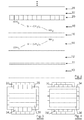
- FIGURE 1 gives a cross-section of a first embodiment of a hard armour composite
- FIGURE 2 gives a cross-section of a second embodiment of a hard armour composite
- FIGURE 3 and FIGURE 4 illustrate how ribbons can be stacked.
- FIGURE 1 gives a cross-section of a first embodiment of hard armour composite.
- the thickness of the various layers illustrated is not in proportion to the real thickness of the various layers.
- the first layer is a backing layer 10 out of fibrous materials.
- Backing layer 10 is bound by means of a binding layer 11 to ceramic plate 12.
- An amino silane layer 14 is the next layer.
- the amino silane can be NH 2 -Si (CH 2 ) n -Si-(OH) 3 .
- the (OH) 3 -group provides the binding with the ceramic plate 12 while the amino-group NH 2 takes care about the binding with the next layer, a polyurethane layer 16.
- the polyurethane layer 16 is a polyurethane emulsion.
- Polypropylene or polyethylene both grafted with maleine anhydride are alternatives for polyurethane.
- the next layer is again an amino silane layer 18 with the amino group binding to the polyurethane layer 16 and the (OH) 3 -group making the binding with a layer of amorphous material 20.
- (OH) 3 -groups make a good binding possible with the metals of the amorphous material 20.
- the amorphous layer 20 is formed by ribbons of amorphous material which preferably do not overlap.
- the width of these ribbons ranges between 20 mm and 30 mm.
- the thickness of the ribbons ranges between 20 ⁇ m and 30 ⁇ m.
- amorphous layer 20 is again an amino silane layer 22, a polyurethane layer 24, an amino silane layer 26, an amorphous layer 28 and so on...
- the stack may comprise between two and fifteen amorphous layers, e.g. four or six.
- a stack as illustrated in FIGURE 1 can be made as follows. Firstly, the various amorphous ribbons are cleaned. Secondly, the surface of these ribbons is modified by means of the amino silanes (by dipping and drying). Thirdly, a polyurethane emulsion is applied by dipping the ribbons in this emulsion. Fourthly a drying period of some minutes is applied. Fifthly the layers of ribbons are connected to one another and /or the layer of ribbons is applied to a ceramic plate. Finally pressure is applied under a high temperature but below 250 °C.
- FIGURE 2 illustrates a second embodiment according to the invention.
- a backing layer 10 is bond by means of a binding layer to a ceramic plate 12.
- An amino silane layer NH 2 -Si (CH 2 ) n -Si-(OH) 3 14 binds the ceramic plate 12 to a polyurethane layer 16.
- a second amino silane layer NH 2 -Si(CH 2 ) n -Si-(OH) 3 18 binds the polyurethane layer 16 to a layer of amorphous ribbons 20.
- a glue foil 32 now binds layer of amorphous ribbons 20 to another layer of amorphous ribbons 28.
- This glue foil 32 can be made of polyurethane or of grafted polypropylene or grafted polyethylene.
- On top of the layer of amorphous ribbons 28 there may be one or more combinations of another glue foil and another layer of amorphous ribbons (not shown).
- FIGURE 3 and FIGURE 4 both illustrate how amorphous ribbons may be positioned.
- the amorphous ribbons are lying next to one another in each layer without overlap.
- the ribbons can be oriented in various directions.
- the ribbons are preferably not woven as the points of crossing form a weak point in transmitting the energy of the bullet.
- the ribbons may be arranged horizontally, in a second layer the ribbons may form an angle of 120° with the ribbons of the first layer and in a third layer the ribbons may form an angle of 240° with the ribbons of the first layer and 120° with the ribbons of the second layer. Viewed from the top, a triangular structure is created offering a high degree of stability.
- Table Material Number of layers Position of layers Type of bullet Result NiFe 4 on ceramic 7,62 AP stopped in ceramic plate NiFe 4 on ceramic 7,62 AP stopped in ceramic plate FeSi 4 on ceramic 7,62 AP stopped in ceramic plate FeSi 4 on ceramic 7,62 AP stopped in ceramic plate NiFe 6 on ceramic 7,62 AP stopped in ceramic plate NiFe 6 on ceramic 7,62 AP stopped in ceramic plate NiFe 4 between 7,62 AP stopped in ceramic plate NiFe 4 between 7,62 AP stopped in backing FeSi 4 between 7,62 AP stopped in ceramic plate FeSi 4 between 7,62 AP stopped in ceramic plate "between” means a positioning of the amorphous ribbons between the ceramic plate and an aramid backing NiFe means 48,6 Fe 39,5 Ni 10,1 Si 1,8 Cr FeSi means 88,1 Fe 11,9 Si
Landscapes
- Engineering & Computer Science (AREA)
- Chemical & Material Sciences (AREA)
- Ceramic Engineering (AREA)
- General Engineering & Computer Science (AREA)
- Laminated Bodies (AREA)
Abstract
A hard armour composite comprises a ceramic plate (12) and a hard metallic sheet (20, 28, 34, 38) having a hardness higher than 650 HV. The hard metallic sheet (20) is bonded to the ceramic plate (12) by means of an adhesion layer (14, 16, 18) with a thickness smaller than 300 µm, preferably smaller than 100 µm.
The hard metallic sheet (20, 28, 34, 38) allows using thinner ceramic plates (12) or ceramic plates (12) which are less expensive.
Description
- The present invention relates to a hard armour composite comprising a ceramic plate.
- For ballistic armour applications two main groups can be distinguished: soft armour for lower-energy projectiles (lower weight and lower velocity) and hard armour for higher-energy projectiles (higher weight and higher velocity).
- Soft armour such as a soft bullet-proof vest may be made from layers of woven aramid or laminated poly-ethylene fibres and protects wearers from projectiles fired from handguns, shotguns and shrapnel from explosives such as hand grenades. Soft armour does not protect the wearer against rifle ammunition (except .22 LR bullets) and amour-piercing bullets with a core of hardened steel.
- Hard armour, however, does provide a protection against rifle ammunition and armour-piercing bullets. Hard armour plates are usually made from metal plates or from ceramics. Hard armour plates are not only used for personal body protection, but also for object protection such as add-on armour for vehicles such as tanks, jeeps, trucks, helicopters, boats, and also for evacuation hospitals, command centres, ...
- The ideal hard armour plate is very light, offers protection according to the desired threat level including multi-hit capability and is available at reasonable cost.
- The cheapest way to apply hard armour is by using steel plates. Steel plates, however, are heavy. This is the reason why current solutions go for ceramic composite plates, enabling a weight reduction of 30% or more.
- Ceramic composite plates are plates where the ceramic material is combined with fibrous materials to avoid the brittle character of pure ceramic material. A ceramic composite plate may have four layers. The first layer and most downstream, i.e. most remote from the bullet, is the backing layer. The backing layer is made of fibrous material. The second layer is a binding layer, binding the backing layer to the third layer. The third layer is the ceramic layer. A fourth layer is the so-called anti-spall liner in the form of a polyamide fabric. The anti-spall liner is placed in front of the ceramic in order to keep the ceramic layer together after the first impact.
- Ceramic composite plates can offer different levels of protection, depending upon the thickness of the ceramic.
For example, a thickness of 6mm - 7 mm ceramic material may offer NIJ level III protection, while a thickness of 8 mm - 10 mm ceramic material may offer NIJ level IV protection. - In addition to the thickness of the ceramic, the type of ceramic also plays an important part in the protection. Alumina (Al2O3) ceramic plates may provide a hardness of 1175 HV up to 1400 HV. Reaction bonded silicon carbide (SiC) may provide hardnesses of up to 2500 HV, sintered SiC may provide a hardness up to 2800 HV and boron carbide (B4C) allows to exceeds levels of hardness of 2900 HV. The higher the level of hardness the thinner the ceramic plates may be, which is an advantage. The density of silicon carbides is 20% lower than the density of alumina and the density of boron carbides is 30% lower than the density of alumina, which also leads to lower weight of the armour plate. The hardness and density advantages, however, can only be obtained by paying a higher price. A reaction bonded SiC plate is three times more expensive than an alumina plate and only provides a doubling in level of hardness. A sintered SiC plate is five times more expensive than an alumina plate. A boron carbide plate is ten to twenty times more expensive than an alumina plate.
- It is an aspect of the present invention to offer a high level of protection without the use of thicker ceramic plates.
It is another aspect of the present invention to offer a high level of protection without resorting to expensive types of ceramic material. It is yet another aspect of the present invention to increase the level of protection of hard armour.
Still another aspect of the present invention is to replace the anti-spall liner. - According to the present invention there is provided hard armour composite. The composite comprises a ceramic plate and a hard metallic sheet having a hardness higher than 650 HV. This hard metallic sheet is bonded to the ceramic plate by means of an adhesion layer with a thickness smaller than 300 µm, preferably smaller than 100 µm. This hard metallic sheet is placed in front of the ceramic plate and may replace the anti-spall layer.
- The hardness is expressed in HV or Vickers hardness. The Vickers hardness test method indents the test material with a diamond indenter, in the form of a right pyramid with a square base and an angle of 136° between opposite faces subjected to a load of 1 kgf to 100 kgf. The full load is normally applied for 10 seconds to 15 seconds. The two diagonals of the indentation left in the surface of the material after removal of the load are measured using a microscope. The average of the two values in calculated. The area of the sloping surface of the indentation is calculated. The HV value is the quotient obtained by dividing the kgf load by the square mm area of indentation. The HV value is normally expressed as a number only, without mentioning the dimensions.
- By using a hard metallic sheet in front of and bonded to the ceramic plate it is possible to reduce the thickness of the ceramic plate e.g. by 2 mm to 3 mm without losing a degree in level of protection.
- In the context of the present invention, the hard metallic sheet may be flat or planar, or curved, or multi-curved.
The term 'sheet' is preferably an independent structure that is to be distinguished from a coating which needs a substrate as support. -
WO-A1-2005/022071 discloses the use of amorphous material in soft and hard body armour in combination with a layer of strong fibbers and with a plurality of layers of plastics material.WO-A1-2005/022071 , however, does not teach the combination of amorphous material in combination with ceramic material. -
WO-A2-2004/106565 discloses a multi-layered structure of amorphous material for bullet resistance. Layers with hardness higher than 9.2 GPa are alternated with layers having a hardness of lower than 9.2 GPa. The amorphous layers, however, are coatings obtained by means of a spraying technique. - According to a preferred embodiment of the invention, the hard metallic sheet comprises one or more ribbons of fully amorphous metallic material, partially amorphous metallic material or metallic material with a nanocrystalline microstructure.
Within the context of the present invention, the terms 'fully amorphous metallic material' refer to a metallic material lacking any crystalline structure, or to a material with a hardly detectable crystallinity (crystal domain size < 5 nm).
The terms 'partially amorphous metallic material' refer to metallic material with only here and there a crystalline structure, the majority of the metallic material remaining amorphous.
The terms 'nanocrystalline structure' refer to a structure where the crystal domains have a maximum dimension of 100 nm.
In what follows, the term 'amorphous' refers to fully amorphous metallic material, partially amorphous metallic material or to metallic material with a nanocrystalline structure. - A particular feature of amorphous material is that it has a high sound velocity. This means that shock waves are transmitted at a high speed through amorphous material. Reflections caused by a penetrating bullet are also transmitted with a high speed. These reflections slow down a penetrating bullet. In amorphous material this slowing down is done quicker than in material with a lower sound velocity. Ribbons do have the advantage over thermal sprayed coatings because these latter have a process-specific and process-related porosity.
- The ribbons may have a width up to 500 mm, preferably ranging from 1 mm to 150 mm.
The ribbons may have a thickness up to 100 µm, preferably ranging from 10 µm to 50 µm. - The hard metallic sheet may comprise a plurality of layers of ribbons of fully amorphous material, partially amorphous material or material with a nanocrystalline microstructure.
The more layers the better, since a penetrating bullet is then confronted with a plurality of hits where the number of hits is in proportion to the number of layers. In addition, the various layers also cause reflections as reaction against a penetrating bullet. This number of reflections is also in proportion to the number of layers. The reflections help to slow down the bullet. - These layers are preferably bound to each other by means of an additional adhesion layer with a thickness smaller than 300 µm, preferably smaller than 100 µm, e.g. smaller than 60 µm.
- The thinner the adhesion layer and the additional adhesion layer and the stronger the bonding of these adhesion layers, the better a bullet can be stopped. The thinner and the stronger this bonding, the more the various layers cooperate with one another to provide a resistance to a bullet. The thinner and the stronger this bonding, the better the shock wave generated by the bullet is reflected.
- The adhesion layer may be selected from the group consisting of a glue foil, a double-sided adhesive tape, a polymer and a primer selected from one or more organo functional silanes, organo functional titanates and organo functional zirconates.
- Similarly, the additional adhesion layer or layers may be selected from the group consisting of a glue foil, a double-sided adhesive tape, a polymer and a primer selected from one or more organo functional silanes, organo functional titanates and organo functional zirconates.
- Preferably, but not exclusively, the organo functional silane primers are selected from the compounds of the following formula:
- Y-(CH2)n-SiX3
-
FIGURE 1 gives a cross-section of a first embodiment of a hard armour composite; -
FIGURE 2 gives a cross-section of a second embodiment of a hard armour composite; -
FIGURE 3 and FIGURE 4 illustrate how ribbons can be stacked. - List of Reference Numbers in the Drawings
- 10
- backing layer
- 11
- binding layer
- 12
- ceramic plate
- 14
- amino silane
- 16
- polyurethane
- 18
- amino silane
- 20
- amorphous ribbon
- 22
- amino silane
- 24
- polyurethane
- 26
- amino silane
- 28
- amorphous ribbon
- 32
- glue foil
- 34
- amorphous ribbon
- 38
- amorphous ribbon
-
FIGURE 1 gives a cross-section of a first embodiment of hard armour composite. The thickness of the various layers illustrated is not in proportion to the real thickness of the various layers. Starting at the back, i.e. at the downstream side, the first layer is abacking layer 10 out of fibrous materials. Backinglayer 10 is bound by means of abinding layer 11 toceramic plate 12. - An
amino silane layer 14 is the next layer. The amino silane can be NH2-Si (CH2)n-Si-(OH)3. The (OH)3-group provides the binding with theceramic plate 12 while the amino-group NH2 takes care about the binding with the next layer, apolyurethane layer 16. - Preferably the
polyurethane layer 16 is a polyurethane emulsion. Polypropylene or polyethylene both grafted with maleine anhydride are alternatives for polyurethane. - The next layer is again an
amino silane layer 18 with the amino group binding to thepolyurethane layer 16 and the (OH)3-group making the binding with a layer ofamorphous material 20. (OH)3-groups make a good binding possible with the metals of theamorphous material 20. - The
amorphous layer 20 is formed by ribbons of amorphous material which preferably do not overlap. The width of these ribbons ranges between 20 mm and 30 mm. The thickness of the ribbons ranges between 20 µm and 30 µm. As a matter of example only, amorphous metals with following compositions have been tested by the inventors: - 88,1
Fe 11,9 Si - 48,6 Fe 39,5
Ni 10,1 Si 1,8 Cr. - Above the
amorphous layer 20 is again anamino silane layer 22, apolyurethane layer 24, anamino silane layer 26, anamorphous layer 28 and so on... The stack may comprise between two and fifteen amorphous layers, e.g. four or six. - A stack as illustrated in
FIGURE 1 can be made as follows. Firstly, the various amorphous ribbons are cleaned. Secondly, the surface of these ribbons is modified by means of the amino silanes (by dipping and drying). Thirdly, a polyurethane emulsion is applied by dipping the ribbons in this emulsion. Fourthly a drying period of some minutes is applied. Fifthly the layers of ribbons are connected to one another and /or the layer of ribbons is applied to a ceramic plate. Finally pressure is applied under a high temperature but below 250 °C. -
FIGURE 2 illustrates a second embodiment according to the invention. Abacking layer 10 is bond by means of a binding layer to aceramic plate 12. An amino silane layer NH2-Si (CH2)n-Si-(OH)3 14 binds theceramic plate 12 to apolyurethane layer 16. A second amino silane layer NH2-Si(CH2)n-Si-(OH)3 18 binds thepolyurethane layer 16 to a layer ofamorphous ribbons 20. Aglue foil 32 now binds layer ofamorphous ribbons 20 to another layer ofamorphous ribbons 28. Thisglue foil 32 can be made of polyurethane or of grafted polypropylene or grafted polyethylene. On top of the layer ofamorphous ribbons 28 there may be one or more combinations of another glue foil and another layer of amorphous ribbons (not shown). -
FIGURE 3 and FIGURE 4 both illustrate how amorphous ribbons may be positioned. The amorphous ribbons are lying next to one another in each layer without overlap. The ribbons can be oriented in various directions. - In
FIGURE 3 , the direction of the ribbons changes 90° with each layer. - In
FIGURE 4 , the direction of the ribbons remains the same in thefirst layers 20 and 28', and changes with 90° for thethird layer 34 andfourth layer 38. - Generally, the ribbons are preferably not woven as the points of crossing form a weak point in transmitting the energy of the bullet.
- Referring both to
FIGURE 3 and FIGURE 4 , following feature - in isolation or in combination with ceramic material - is relevant with respect to bullet resistance. Take as example layers 20 and 34 ofFIGURE 3 orlayer 20 and 28' ofFIGURE 4 . In all these layers the amorphous ribbons run parallel. In the embodiment ofFIGURE 3 , viewed from above the line of separation between two adjacent ribbons inlayer 20 does not coincide with the line of separation between two adjacent ribbons inlayer 34. In the embodiment ofFIGURE 4 , the line of separation between two adjacent ribbons inlayer 20 does not coincide with the line of separation between two adjacent ribbons in layer 28'. Such a line of separation may form a weak point in the trajectory of a penetrating bullet. By shifting the ribbons somewhat in the various layers, it is avoided that a penetrating bullet meets two weak points in its trajectory. - Other configurations are also possible. For example, in a first layer the ribbons may be arranged horizontally, in a second layer the ribbons may form an angle of 120° with the ribbons of the first layer and in a third layer the ribbons may form an angle of 240° with the ribbons of the first layer and 120° with the ribbons of the second layer. Viewed from the top, a triangular structure is created offering a high degree of stability.
- Tests
- The table hereunder illustrates the effectiveness of having layers of amorphous ribbons on top of a ceramic plate.
Table Material Number of layers Position of layers Type of bullet Result NiFe 4 on ceramic 7,62 AP stopped in ceramic plate NiFe 4 on ceramic 7,62 AP stopped in ceramic plate FeSi 4 on ceramic 7,62 AP stopped in ceramic plate FeSi 4 on ceramic 7,62 AP stopped in ceramic plate NiFe 6 on ceramic 7,62 AP stopped in ceramic plate NiFe 6 on ceramic 7,62 AP stopped in ceramic plate NiFe 4 between 7,62 AP stopped in ceramic plate NiFe 4 between 7,62 AP stopped in backing FeSi 4 between 7,62 AP stopped in ceramic plate FeSi 4 between 7,62 AP stopped in ceramic plate "between" means a positioning of the amorphous ribbons between the ceramic plate and an aramid backing
NiFe means 48,6 Fe 39,5Ni 10,1 Si 1,8 Cr
FeSi means 88,1Fe 11,9 Si
Y represents an organo functional group selected from -NH2, CH2=CH-, CH2=C(CH3)COO-, 2,3-epoxypropoxy, HS- and, Cl-
X represents a silicon functional group selected from -OR, -OC(=O)R', -Cl wherein R and R' are independently selected from C1 to C4 alkyl, preferably -CH3, and -C2H5; and
n is an integer between 0 and 10, preferably from 0 to 10 and most preferably from 0 to 3.
The organo functional silanes described above are commercially available products.
Claims (12)
- A hard armour composite comprising a ceramic plate
characterized in that
said composite further comprises a hard metallic sheet having a hardness higher than 650 HV, said hard metallic sheet being bonded to said ceramic plate by means of an adhesion layer with a thickness smaller than 300 µm, preferably smaller than 100 µm. - A composite according to claim 1,
wherein said hard metallic sheet comprises one or more ribbons of fully amorphous metallic material, partially amorphous metallic material or metallic material with a nanocrystalline microstructure. - A composite according to claim 2,
wherein said ribbons have a width smaller than 500 mm, and preferably ranging from 1 mm to 150 mm. - A composite according to claim 2 or 3,
wherein said ribbons have a thickness smaller than 100 µm, and preferably ranging from 10 µm to 50 µm. - A composite according to any one of claims 2 to 4,
wherein said hard metallic sheet comprises a plurality of layers of said ribbons of fully amorphous metallic material, partially amorphous metallic material or metallic material with a nanocrystalline microstructure. - A composite according to claim 5, wherein said plurality of layers are bound to each other by means of an additional adhesion layer with a thickness smaller than 300 µm.
- A composite according to any of the preceding claims,
wherein said adhesion layer is selected from the group consisting of a glue foil, a double-sided adhesive tape, a polymer and a primer selected from one or more organo functional silanes, organo functional titanates and organo functional zirconates, or a combination thereof. - A composite according to claim 6 or 7,
wherein said additional adhesion layer is selected from the group consisting of a glue foil, a double-sided adhesive tape, a polymer and a primer selected from one or more organo functional silanes, organo functional titanates and organo functional zirconates, or a combination thereof. - A composite according to any of the preceding claims,
wherein said hard metallic sheet forms the front side. - Use of a composite according to any of claims 1 to 9 as a hard armour.
- Use of a composite according to any of claims 1 to 9 as body armour.
- Use of a composite according to any of claims 1 to 9 as add on for protection of vehicles.
Priority Applications (1)
| Application Number | Priority Date | Filing Date | Title |
|---|---|---|---|
| EP07150054A EP2072944A1 (en) | 2007-12-17 | 2007-12-17 | Hard armour with amophous metallic sheet |
Applications Claiming Priority (1)
| Application Number | Priority Date | Filing Date | Title |
|---|---|---|---|
| EP07150054A EP2072944A1 (en) | 2007-12-17 | 2007-12-17 | Hard armour with amophous metallic sheet |
Publications (1)
| Publication Number | Publication Date |
|---|---|
| EP2072944A1 true EP2072944A1 (en) | 2009-06-24 |
Family
ID=39391417
Family Applications (1)
| Application Number | Title | Priority Date | Filing Date |
|---|---|---|---|
| EP07150054A Withdrawn EP2072944A1 (en) | 2007-12-17 | 2007-12-17 | Hard armour with amophous metallic sheet |
Country Status (1)
| Country | Link |
|---|---|
| EP (1) | EP2072944A1 (en) |
Citations (4)
| Publication number | Priority date | Publication date | Assignee | Title |
|---|---|---|---|---|
| WO1996004134A1 (en) * | 1994-08-01 | 1996-02-15 | Amorphus Alloys Corp. | Amorphous metal/reinforcement composite material |
| WO2003078158A1 (en) * | 2002-03-11 | 2003-09-25 | Liquidmetal Technologies | Encapsulated ceramic armor |
| WO2004106565A2 (en) | 2003-05-23 | 2004-12-09 | The Nanosteel Company | Layered metallic material formed from iron based glass alloys |
| WO2005022071A1 (en) | 2003-08-29 | 2005-03-10 | Isis Innovation Limited | Body armour |
-
2007
- 2007-12-17 EP EP07150054A patent/EP2072944A1/en not_active Withdrawn
Patent Citations (4)
| Publication number | Priority date | Publication date | Assignee | Title |
|---|---|---|---|---|
| WO1996004134A1 (en) * | 1994-08-01 | 1996-02-15 | Amorphus Alloys Corp. | Amorphous metal/reinforcement composite material |
| WO2003078158A1 (en) * | 2002-03-11 | 2003-09-25 | Liquidmetal Technologies | Encapsulated ceramic armor |
| WO2004106565A2 (en) | 2003-05-23 | 2004-12-09 | The Nanosteel Company | Layered metallic material formed from iron based glass alloys |
| WO2005022071A1 (en) | 2003-08-29 | 2005-03-10 | Isis Innovation Limited | Body armour |
Similar Documents
| Publication | Publication Date | Title |
|---|---|---|
| US6497966B2 (en) | Laminated armor | |
| US7300893B2 (en) | Armor including a strain rate hardening elastomer | |
| US5677029A (en) | Ballistic resistant fabric articles | |
| US7562612B2 (en) | Ceramic components, ceramic component systems, and ceramic armour systems | |
| KR100529534B1 (en) | Ceramic bodies for use in composite armor | |
| EP1737653A2 (en) | Armor including a strain rate hardening elastomer | |
| AU2002223998A1 (en) | Laminated armor | |
| CA2526990C (en) | Layered metallic material formed from iron based glass alloys | |
| TWI409172B (en) | Improved liquid submersion ballistic performance through hybridization | |
| EP1666829A1 (en) | An armour plate for use in personal or vehicular armour | |
| CN101678636A (en) | Inhibition of water penetration into ballistic materials | |
| US20120055327A1 (en) | Armor system having ceramic matrix composite layers | |
| US20110008598A1 (en) | Protective panel | |
| EP1298407A1 (en) | Antiballistic armor and method of manufacturing it | |
| CA2568559A1 (en) | Method of forming adhesive mixtures and ballistic composites utilizing the same | |
| CN216049450U (en) | Multilayer composite structure bulletproof armor for helicopter cockpit | |
| CN117048146B (en) | A multi-component composite aluminum alloy/ceramic protective material and preparation method thereof | |
| GB2336807A (en) | Ceramic sandwich material for ballistic protection | |
| JP5330071B2 (en) | Impact resistant member, human body protective clothing, and method of manufacturing impact resistant member | |
| EP2072944A1 (en) | Hard armour with amophous metallic sheet | |
| WO2008105929A2 (en) | Method of forming adhesive mixtures and ballistic composites utilizing the same | |
| US12247811B2 (en) | Armor plate, armor plate composite and armor | |
| JP7563827B2 (en) | Ballistic Protection Materials | |
| JP2010175211A (en) | Impact resistant member | |
| JPH0584440B2 (en) |
Legal Events
| Date | Code | Title | Description |
|---|---|---|---|
| PUAI | Public reference made under article 153(3) epc to a published international application that has entered the european phase |
Free format text: ORIGINAL CODE: 0009012 |
|
| AK | Designated contracting states |
Kind code of ref document: A1 Designated state(s): AT BE BG CH CY CZ DE DK EE ES FI FR GB GR HU IE IS IT LI LT LU LV MC MT NL PL PT RO SE SI SK TR |
|
| AX | Request for extension of the european patent |
Extension state: AL BA HR MK RS |
|
| AKX | Designation fees paid | ||
| REG | Reference to a national code |
Ref country code: DE Ref legal event code: 8566 |
|
| STAA | Information on the status of an ep patent application or granted ep patent |
Free format text: STATUS: THE APPLICATION IS DEEMED TO BE WITHDRAWN |
|
| 18D | Application deemed to be withdrawn |
Effective date: 20091229 |