EP2072629A1 - Ultra-passivation of chromium-containing alloy - Google Patents
Ultra-passivation of chromium-containing alloy Download PDFInfo
- Publication number
- EP2072629A1 EP2072629A1 EP08162563A EP08162563A EP2072629A1 EP 2072629 A1 EP2072629 A1 EP 2072629A1 EP 08162563 A EP08162563 A EP 08162563A EP 08162563 A EP08162563 A EP 08162563A EP 2072629 A1 EP2072629 A1 EP 2072629A1
- Authority
- EP
- European Patent Office
- Prior art keywords
- acid
- passivation
- treatment
- plasma
- chromium
- Prior art date
- Legal status (The legal status is an assumption and is not a legal conclusion. Google has not performed a legal analysis and makes no representation as to the accuracy of the status listed.)
- Granted
Links
- 239000011651 chromium Substances 0.000 title claims abstract description 43
- 229910052804 chromium Inorganic materials 0.000 title claims abstract description 16
- VYZAMTAEIAYCRO-UHFFFAOYSA-N Chromium Chemical compound [Cr] VYZAMTAEIAYCRO-UHFFFAOYSA-N 0.000 title claims abstract description 15
- 238000002161 passivation Methods 0.000 title description 33
- 229910045601 alloy Inorganic materials 0.000 title description 12
- 239000000956 alloy Substances 0.000 title description 12
- 238000000034 method Methods 0.000 claims abstract description 57
- 239000000463 material Substances 0.000 claims abstract description 32
- 239000002253 acid Substances 0.000 claims abstract description 30
- 239000007789 gas Substances 0.000 claims description 37
- VEXZGXHMUGYJMC-UHFFFAOYSA-N Hydrochloric acid Chemical compound Cl VEXZGXHMUGYJMC-UHFFFAOYSA-N 0.000 claims description 28
- GRYLNZFGIOXLOG-UHFFFAOYSA-N Nitric acid Chemical compound O[N+]([O-])=O GRYLNZFGIOXLOG-UHFFFAOYSA-N 0.000 claims description 25
- 229910017604 nitric acid Inorganic materials 0.000 claims description 24
- 229910052760 oxygen Inorganic materials 0.000 claims description 14
- QVGXLLKOCUKJST-UHFFFAOYSA-N atomic oxygen Chemical compound [O] QVGXLLKOCUKJST-UHFFFAOYSA-N 0.000 claims description 12
- 239000001301 oxygen Substances 0.000 claims description 12
- XKRFYHLGVUSROY-UHFFFAOYSA-N Argon Chemical compound [Ar] XKRFYHLGVUSROY-UHFFFAOYSA-N 0.000 claims description 10
- 229910052786 argon Inorganic materials 0.000 claims description 5
- IVMYJDGYRUAWML-UHFFFAOYSA-N cobalt(ii) oxide Chemical class [Co]=O IVMYJDGYRUAWML-UHFFFAOYSA-N 0.000 claims description 4
- 239000001307 helium Substances 0.000 claims description 3
- 229910052734 helium Inorganic materials 0.000 claims description 3
- SWQJXJOGLNCZEY-UHFFFAOYSA-N helium atom Chemical compound [He] SWQJXJOGLNCZEY-UHFFFAOYSA-N 0.000 claims description 3
- 230000008569 process Effects 0.000 description 33
- 238000004833 X-ray photoelectron spectroscopy Methods 0.000 description 30
- 239000010410 layer Substances 0.000 description 27
- 238000011282 treatment Methods 0.000 description 26
- 238000005260 corrosion Methods 0.000 description 19
- 230000007797 corrosion Effects 0.000 description 19
- 229910000684 Cobalt-chrome Inorganic materials 0.000 description 16
- 239000010952 cobalt-chrome Substances 0.000 description 16
- 238000009832 plasma treatment Methods 0.000 description 16
- 239000007943 implant Substances 0.000 description 15
- 239000000203 mixture Substances 0.000 description 15
- 239000000523 sample Substances 0.000 description 14
- 230000001590 oxidative effect Effects 0.000 description 13
- 230000003647 oxidation Effects 0.000 description 11
- 238000007254 oxidation reaction Methods 0.000 description 11
- 150000002500 ions Chemical class 0.000 description 10
- WGLPBDUCMAPZCE-UHFFFAOYSA-N Trioxochromium Chemical compound O=[Cr](=O)=O WGLPBDUCMAPZCE-UHFFFAOYSA-N 0.000 description 9
- 229910000423 chromium oxide Inorganic materials 0.000 description 9
- 229910052751 metal Inorganic materials 0.000 description 9
- 239000002184 metal Substances 0.000 description 9
- 238000010306 acid treatment Methods 0.000 description 7
- 239000000243 solution Substances 0.000 description 7
- IJGRMHOSHXDMSA-UHFFFAOYSA-N Atomic nitrogen Chemical compound N#N IJGRMHOSHXDMSA-UHFFFAOYSA-N 0.000 description 6
- VYPSYNLAJGMNEJ-UHFFFAOYSA-N Silicium dioxide Chemical compound O=[Si]=O VYPSYNLAJGMNEJ-UHFFFAOYSA-N 0.000 description 6
- HEMHJVSKTPXQMS-UHFFFAOYSA-M Sodium hydroxide Chemical compound [OH-].[Na+] HEMHJVSKTPXQMS-UHFFFAOYSA-M 0.000 description 6
- 238000004458 analytical method Methods 0.000 description 6
- KRKNYBCHXYNGOX-UHFFFAOYSA-N citric acid Chemical compound OC(=O)CC(O)(C(O)=O)CC(O)=O KRKNYBCHXYNGOX-UHFFFAOYSA-N 0.000 description 6
- 229910017052 cobalt Inorganic materials 0.000 description 5
- 239000010941 cobalt Substances 0.000 description 5
- GUTLYIVDDKVIGB-UHFFFAOYSA-N cobalt atom Chemical compound [Co] GUTLYIVDDKVIGB-UHFFFAOYSA-N 0.000 description 5
- QDOXWKRWXJOMAK-UHFFFAOYSA-N dichromium trioxide Chemical compound O=[Cr]O[Cr]=O QDOXWKRWXJOMAK-UHFFFAOYSA-N 0.000 description 4
- 238000001095 inductively coupled plasma mass spectrometry Methods 0.000 description 4
- 239000010935 stainless steel Substances 0.000 description 4
- 229910001220 stainless steel Inorganic materials 0.000 description 4
- XLYOFNOQVPJJNP-UHFFFAOYSA-N water Substances O XLYOFNOQVPJJNP-UHFFFAOYSA-N 0.000 description 4
- 229910001868 water Inorganic materials 0.000 description 4
- 230000015572 biosynthetic process Effects 0.000 description 3
- 238000004140 cleaning Methods 0.000 description 3
- 229910052681 coesite Inorganic materials 0.000 description 3
- 229910052906 cristobalite Inorganic materials 0.000 description 3
- 239000011261 inert gas Substances 0.000 description 3
- 229910021645 metal ion Inorganic materials 0.000 description 3
- 229910052757 nitrogen Inorganic materials 0.000 description 3
- 239000000377 silicon dioxide Substances 0.000 description 3
- 238000004544 sputter deposition Methods 0.000 description 3
- 229910052682 stishovite Inorganic materials 0.000 description 3
- 229910052905 tridymite Inorganic materials 0.000 description 3
- MHAJPDPJQMAIIY-UHFFFAOYSA-N Hydrogen peroxide Chemical compound OO MHAJPDPJQMAIIY-UHFFFAOYSA-N 0.000 description 2
- XEEYBQQBJWHFJM-UHFFFAOYSA-N Iron Chemical compound [Fe] XEEYBQQBJWHFJM-UHFFFAOYSA-N 0.000 description 2
- QAOWNCQODCNURD-UHFFFAOYSA-N Sulfuric acid Chemical compound OS(O)(=O)=O QAOWNCQODCNURD-UHFFFAOYSA-N 0.000 description 2
- 239000012670 alkaline solution Substances 0.000 description 2
- 210000001124 body fluid Anatomy 0.000 description 2
- 239000010839 body fluid Substances 0.000 description 2
- 210000000988 bone and bone Anatomy 0.000 description 2
- 229910000428 cobalt oxide Inorganic materials 0.000 description 2
- 230000007423 decrease Effects 0.000 description 2
- 239000003599 detergent Substances 0.000 description 2
- 238000001035 drying Methods 0.000 description 2
- 210000002391 femur head Anatomy 0.000 description 2
- 238000011540 hip replacement Methods 0.000 description 2
- 238000013150 knee replacement Methods 0.000 description 2
- 150000001247 metal acetylides Chemical class 0.000 description 2
- 229910044991 metal oxide Inorganic materials 0.000 description 2
- 150000004706 metal oxides Chemical class 0.000 description 2
- 230000001681 protective effect Effects 0.000 description 2
- 230000009467 reduction Effects 0.000 description 2
- 230000002269 spontaneous effect Effects 0.000 description 2
- 239000000126 substance Substances 0.000 description 2
- 239000000758 substrate Substances 0.000 description 2
- 239000002344 surface layer Substances 0.000 description 2
- 230000003746 surface roughness Effects 0.000 description 2
- 238000004506 ultrasonic cleaning Methods 0.000 description 2
- 241000124008 Mammalia Species 0.000 description 1
- 241001465754 Metazoa Species 0.000 description 1
- 239000004698 Polyethylene Substances 0.000 description 1
- FAPWRFPIFSIZLT-UHFFFAOYSA-M Sodium chloride Chemical compound [Na+].[Cl-] FAPWRFPIFSIZLT-UHFFFAOYSA-M 0.000 description 1
- WAIPAZQMEIHHTJ-UHFFFAOYSA-N [Cr].[Co] Chemical compound [Cr].[Co] WAIPAZQMEIHHTJ-UHFFFAOYSA-N 0.000 description 1
- MTHLBYMFGWSRME-UHFFFAOYSA-N [Cr].[Co].[Mo] Chemical compound [Cr].[Co].[Mo] MTHLBYMFGWSRME-UHFFFAOYSA-N 0.000 description 1
- 230000009471 action Effects 0.000 description 1
- 229910052782 aluminium Inorganic materials 0.000 description 1
- XAGFODPZIPBFFR-UHFFFAOYSA-N aluminium Chemical compound [Al] XAGFODPZIPBFFR-UHFFFAOYSA-N 0.000 description 1
- 230000008901 benefit Effects 0.000 description 1
- 239000012888 bovine serum Substances 0.000 description 1
- 239000000919 ceramic Substances 0.000 description 1
- 230000008859 change Effects 0.000 description 1
- 238000011109 contamination Methods 0.000 description 1
- 230000003247 decreasing effect Effects 0.000 description 1
- 238000005238 degreasing Methods 0.000 description 1
- 238000004090 dissolution Methods 0.000 description 1
- 230000000694 effects Effects 0.000 description 1
- 230000002708 enhancing effect Effects 0.000 description 1
- 238000010438 heat treatment Methods 0.000 description 1
- 238000007654 immersion Methods 0.000 description 1
- 238000001727 in vivo Methods 0.000 description 1
- 238000009616 inductively coupled plasma Methods 0.000 description 1
- 230000003993 interaction Effects 0.000 description 1
- 229910052742 iron Inorganic materials 0.000 description 1
- 150000002506 iron compounds Chemical class 0.000 description 1
- 210000003127 knee Anatomy 0.000 description 1
- 229910052743 krypton Inorganic materials 0.000 description 1
- DNNSSWSSYDEUBZ-UHFFFAOYSA-N krypton atom Chemical compound [Kr] DNNSSWSSYDEUBZ-UHFFFAOYSA-N 0.000 description 1
- 238000002386 leaching Methods 0.000 description 1
- 239000007788 liquid Substances 0.000 description 1
- 230000007774 longterm Effects 0.000 description 1
- 238000004519 manufacturing process Methods 0.000 description 1
- 229910052754 neon Inorganic materials 0.000 description 1
- GKAOGPIIYCISHV-UHFFFAOYSA-N neon atom Chemical compound [Ne] GKAOGPIIYCISHV-UHFFFAOYSA-N 0.000 description 1
- 150000004767 nitrides Chemical class 0.000 description 1
- 239000007800 oxidant agent Substances 0.000 description 1
- 238000005498 polishing Methods 0.000 description 1
- 229920000573 polyethylene Polymers 0.000 description 1
- 238000001223 reverse osmosis Methods 0.000 description 1
- 230000035945 sensitivity Effects 0.000 description 1
- 239000012890 simulated body fluid Substances 0.000 description 1
- 238000002791 soaking Methods 0.000 description 1
- 241000894007 species Species 0.000 description 1
- 239000001117 sulphuric acid Substances 0.000 description 1
- 235000011149 sulphuric acid Nutrition 0.000 description 1
- 230000004580 weight loss Effects 0.000 description 1
- 229910052724 xenon Inorganic materials 0.000 description 1
- FHNFHKCVQCLJFQ-UHFFFAOYSA-N xenon atom Chemical compound [Xe] FHNFHKCVQCLJFQ-UHFFFAOYSA-N 0.000 description 1
Images



Classifications
-
- C—CHEMISTRY; METALLURGY
- C23—COATING METALLIC MATERIAL; COATING MATERIAL WITH METALLIC MATERIAL; CHEMICAL SURFACE TREATMENT; DIFFUSION TREATMENT OF METALLIC MATERIAL; COATING BY VACUUM EVAPORATION, BY SPUTTERING, BY ION IMPLANTATION OR BY CHEMICAL VAPOUR DEPOSITION, IN GENERAL; INHIBITING CORROSION OF METALLIC MATERIAL OR INCRUSTATION IN GENERAL
- C23C—COATING METALLIC MATERIAL; COATING MATERIAL WITH METALLIC MATERIAL; SURFACE TREATMENT OF METALLIC MATERIAL BY DIFFUSION INTO THE SURFACE, BY CHEMICAL CONVERSION OR SUBSTITUTION; COATING BY VACUUM EVAPORATION, BY SPUTTERING, BY ION IMPLANTATION OR BY CHEMICAL VAPOUR DEPOSITION, IN GENERAL
- C23C30/00—Coating with metallic material characterised only by the composition of the metallic material, i.e. not characterised by the coating process
-
- A—HUMAN NECESSITIES
- A61—MEDICAL OR VETERINARY SCIENCE; HYGIENE
- A61L—METHODS OR APPARATUS FOR STERILISING MATERIALS OR OBJECTS IN GENERAL; DISINFECTION, STERILISATION OR DEODORISATION OF AIR; CHEMICAL ASPECTS OF BANDAGES, DRESSINGS, ABSORBENT PADS OR SURGICAL ARTICLES; MATERIALS FOR BANDAGES, DRESSINGS, ABSORBENT PADS OR SURGICAL ARTICLES
- A61L27/00—Materials for grafts or prostheses or for coating grafts or prostheses
- A61L27/02—Inorganic materials
- A61L27/04—Metals or alloys
- A61L27/047—Other specific metals or alloys not covered by A61L27/042 - A61L27/045 or A61L27/06
-
- A—HUMAN NECESSITIES
- A61—MEDICAL OR VETERINARY SCIENCE; HYGIENE
- A61L—METHODS OR APPARATUS FOR STERILISING MATERIALS OR OBJECTS IN GENERAL; DISINFECTION, STERILISATION OR DEODORISATION OF AIR; CHEMICAL ASPECTS OF BANDAGES, DRESSINGS, ABSORBENT PADS OR SURGICAL ARTICLES; MATERIALS FOR BANDAGES, DRESSINGS, ABSORBENT PADS OR SURGICAL ARTICLES
- A61L27/00—Materials for grafts or prostheses or for coating grafts or prostheses
- A61L27/28—Materials for coating prostheses
- A61L27/30—Inorganic materials
- A61L27/306—Other specific inorganic materials not covered by A61L27/303 - A61L27/32
-
- A—HUMAN NECESSITIES
- A61—MEDICAL OR VETERINARY SCIENCE; HYGIENE
- A61L—METHODS OR APPARATUS FOR STERILISING MATERIALS OR OBJECTS IN GENERAL; DISINFECTION, STERILISATION OR DEODORISATION OF AIR; CHEMICAL ASPECTS OF BANDAGES, DRESSINGS, ABSORBENT PADS OR SURGICAL ARTICLES; MATERIALS FOR BANDAGES, DRESSINGS, ABSORBENT PADS OR SURGICAL ARTICLES
- A61L27/00—Materials for grafts or prostheses or for coating grafts or prostheses
- A61L27/50—Materials characterised by their function or physical properties, e.g. injectable or lubricating compositions, shape-memory materials, surface modified materials
-
- A—HUMAN NECESSITIES
- A61—MEDICAL OR VETERINARY SCIENCE; HYGIENE
- A61P—SPECIFIC THERAPEUTIC ACTIVITY OF CHEMICAL COMPOUNDS OR MEDICINAL PREPARATIONS
- A61P43/00—Drugs for specific purposes, not provided for in groups A61P1/00-A61P41/00
-
- C—CHEMISTRY; METALLURGY
- C22—METALLURGY; FERROUS OR NON-FERROUS ALLOYS; TREATMENT OF ALLOYS OR NON-FERROUS METALS
- C22C—ALLOYS
- C22C27/00—Alloys based on rhenium or a refractory metal not mentioned in groups C22C14/00 or C22C16/00
- C22C27/06—Alloys based on chromium
-
- C—CHEMISTRY; METALLURGY
- C23—COATING METALLIC MATERIAL; COATING MATERIAL WITH METALLIC MATERIAL; CHEMICAL SURFACE TREATMENT; DIFFUSION TREATMENT OF METALLIC MATERIAL; COATING BY VACUUM EVAPORATION, BY SPUTTERING, BY ION IMPLANTATION OR BY CHEMICAL VAPOUR DEPOSITION, IN GENERAL; INHIBITING CORROSION OF METALLIC MATERIAL OR INCRUSTATION IN GENERAL
- C23C—COATING METALLIC MATERIAL; COATING MATERIAL WITH METALLIC MATERIAL; SURFACE TREATMENT OF METALLIC MATERIAL BY DIFFUSION INTO THE SURFACE, BY CHEMICAL CONVERSION OR SUBSTITUTION; COATING BY VACUUM EVAPORATION, BY SPUTTERING, BY ION IMPLANTATION OR BY CHEMICAL VAPOUR DEPOSITION, IN GENERAL
- C23C22/00—Chemical surface treatment of metallic material by reaction of the surface with a reactive liquid, leaving reaction products of surface material in the coating, e.g. conversion coatings, passivation of metals
- C23C22/05—Chemical surface treatment of metallic material by reaction of the surface with a reactive liquid, leaving reaction products of surface material in the coating, e.g. conversion coatings, passivation of metals using aqueous solutions
- C23C22/06—Chemical surface treatment of metallic material by reaction of the surface with a reactive liquid, leaving reaction products of surface material in the coating, e.g. conversion coatings, passivation of metals using aqueous solutions using aqueous acidic solutions with pH less than 6
- C23C22/48—Chemical surface treatment of metallic material by reaction of the surface with a reactive liquid, leaving reaction products of surface material in the coating, e.g. conversion coatings, passivation of metals using aqueous solutions using aqueous acidic solutions with pH less than 6 not containing phosphates, hexavalent chromium compounds, fluorides or complex fluorides, molybdates, tungstates, vanadates or oxalates
- C23C22/58—Treatment of other metallic material
-
- Y—GENERAL TAGGING OF NEW TECHNOLOGICAL DEVELOPMENTS; GENERAL TAGGING OF CROSS-SECTIONAL TECHNOLOGIES SPANNING OVER SEVERAL SECTIONS OF THE IPC; TECHNICAL SUBJECTS COVERED BY FORMER USPC CROSS-REFERENCE ART COLLECTIONS [XRACs] AND DIGESTS
- Y10—TECHNICAL SUBJECTS COVERED BY FORMER USPC
- Y10T—TECHNICAL SUBJECTS COVERED BY FORMER US CLASSIFICATION
- Y10T428/00—Stock material or miscellaneous articles
- Y10T428/26—Web or sheet containing structurally defined element or component, the element or component having a specified physical dimension
Definitions
- This invention relates to a method for treating a chromium containing alloy.
- a chromium containing alloy might be used in a orthopaedic joint prosthesis.
- Metal-on-metal (MOM) prosthesis implants have been around since the 1960s.
- MOM Metal-on-metal
- MOP metal-on-polyethylene
- MOM devices there is still concern regarding the long term effects of in vivo metal ion release due to corrosion and/or wear of the metal components.
- chromium containing alloys for example CoCr and CoCrMo alloys
- the corrosion resistance of chromium containing alloys is thought to be due to the existence of a natural metal oxide layer on the alloy surface.
- the major components of this oxide layer are cobalt oxide and chromium oxide. Because chromium oxide is much more resistant to leaching by body fluids than cobalt oxide, the corrosion resistance of the alloy depends on the continuity, thickness and chromium oxide content of the layer.
- CoCr implants are routinely treated by immersion in 30% nitric acid solution at an elevated temperature (54°C). It is believed by many in the industry that passivating CoCr materials with nitric or citric acid leads to the production of a corrosion resistant surface by forming a thin transparent Chromium oxide film. It is this layer that they believe imparts the corrosion resistance to CoCr implant materials. These beliefs are based on work published for stainless steel passivation. In reality, the surface of a nitric (citric) acid passivated surface has a surface composition of approximately 50:50 Co and Cr.
- MOM implants are also subject to weight loss caused by the continuous friction of two contacted surfaces moving in body fluid. As these surfaces contact each other, the interaction of asperities or surface roughness causes wear.
- One aspect of the present invention concerns chromium containing, such as CoCrMo, articles having a surface oxide layer up to 20 nm thick, said surface oxide layer comprising chromium and cobalt oxides where the atomic ratio of Cr/Co is at least about 3.
- the invention concerns a method comprising: contacting the chromium containing material with a gas plasma under conditions effective to oxidise at least a portion of the material; and contacting the material with an acid under conditions effective to form a robust Chromium oxide surface layer substantially thicker than that produced using the conventional process described above.
- the material can be contacted with the gas plasma before it is contacted with the acid or the material can be contacted with the acid before and after it is contacted with the gas plasma.
- the acid can include nitric acid or hydrochloric acid.
- the acid includes hydrochloric acid and the first acid passivation treatment is followed by a second acid passivation treatment using an acid comprising nitric acid.
- the gas plasma used in the methods of the invention can be derived from an oxidative gas or from a mixture of gases comprising oxidative gas and optionally one or more inert gases.
- One preferred oxidative gas is oxygen.
- Inert gases include nitrogen, argon and helium.
- the material is contacted with the gas plasma for about 5 to about 120 minutes.
- the contacting of the material with the gas plasma is performed at a power of about 100 to about 1000 watts.
- the mixture of gasses comprises at least 3 % (v/v) percent oxidative gas.
- Other embodiments contain 100% (v/v) percent oxidative gas.
- the invention also concerns articles made by the methods of the invention.
- the invention concerns articles comprising cobalt and chromium, the article having a surface comprising oxides where the oxides are characterized with a Cr/Co ratio of at least about 3 (as measured by XPS).
- the oxides are characterized by a Cr/Co ratio of about 7.
- the surface oxide is 3 to 8 nm thick. This highly enriched chromium oxide layer impart a significantly higher corrosion resistance versus the relatively thin (for example from about 1 nm to about 2 nm) passive film formed using a conventional passivation process.
- Some articles are designed to be implantable into a mammal. Certain of these articles are joint replacement prosthesis or component thereof. Such prosthesis include hip or knee replacement prosthesis.
- the treated material is used on a wear surface, especially an orthopaedic implant wear surface to reduce wear.
- Some articles are very corrosion resistant and they can be used in corrosive environment, including acid or alkaline environments.
- the inventive passivation film can reduce the ion release in simulated body fluid.
- the invention also concerns methods comprising implanting a prosthesis comprising chromium and cobalt in a human or animal body in contact with bone, in which at least a portion of the prosthesis in contact with said bone comprising a surface having an exterior oxide layer of up to 20 nm in thickness that is highly enriched in chromium oxide.
- the present invention provides chromium containing articles and devices having thick and Cr highly enriched surface oxide layers, and processes to make improved wear surfaces on chromium containing materials.
- This surface preferably has a strengthened passive film, which can reduce ion release rates by decreasing the corrosion rate. Wear is believed to be reduced by protecting the wear surface from selective corrosion in surrounding carbide areas.
- One type of process according to the invention includes plasma oxidation and acid treatment. The acid treatment can be conducted after plasma oxidation or both before and after plasma oxidation.
- Certain processes involve the steps of subjecting a cobalt- and chromium-containing implant material to an energetic, oxidative gas plasma and treating the implant material with acid.
- This acid treatment can be achieved after plasma oxidation or before and after plasma oxidation.
- the plasma treatment process can be achieved using an oxidative gas such as oxygen or a mixture of oxidative gases and inert gases at a power of between 100 and 1000 watts for a time of between 5 minutes to 120 minutes.
- the one obtained from the inventive process preferably is thicker and the Cr/Co ratio is higher.
- the enhancement of the oxide is believed to reduce the amount of metal ion release due to corrosion and/or wear.
- surfaces are treated with a gas plasma under conditions effective to oxidise at least a portion of the surface.
- the oxidative component of the gas can comprise oxygen, water, hydrogen peroxide, or mixtures thereof.
- the oxidative gas plasma can be formed, for example, from oxygen, a mixture of oxygen with air, or with one of the foregoing along with one or more non-reducible gases.
- Non-reducible gases include argon, nitrogen, neon, helium, xenon, and krypton.
- argon is preferred.
- the amount of oxygen in the gas is greater than 3%. In some preferred embodiments, the amount of oxygen in the gas is 3% to 100%
- a plasma is generated by creating an electrical discharge in a gaseous atmosphere under suitable pressure conditions.
- a typical plasma treatment system has a chamber capable of being maintained at a desired pressure (typically atmospheric or below). The surface to be treated is placed with the chamber with the selected gas and an appropriate electrical discharge is applied to the chamber.
- a desired pressure typically atmospheric or below.
- the surface to be treated is placed with the chamber with the selected gas and an appropriate electrical discharge is applied to the chamber.
- a number of gas plasma treatment systems suitable for use in the practice of the present invention are commercially available and such systems are generally known.
- the energy source used in the gas plasma oxidation is one capable of supplying a sufficient amount of energy to ionise at least a portion of oxidative gas to form a gas plasma.
- At least three power sources have been widely used in practice to supply the energy. These include DC electrical energy, radio frequency (RF) energy, and microwave energy.
- RF energy sources typically have the greatest sensitivity and are the freest from interference. Thus, in some embodiments, a RF energy source is preferred.
- the amount of energy utilized to form the plasma is typically from about 100 to about 1000 watts. In some preferred embodiments, the amount of energy is from about 800 to about 1000 watts.
- the gas plasma treatment of the surface is typically performed for about 5 to about 120 minutes. In some embodiments, the time is from about 30 to about 90 minutes. In other embodiments, however, the time is at least 60 minutes.
- the pressure at which the gas plasma oxidation is performed is typically from atmospheric pressure to sub-atmospheric pressure. In some embodiments, the pressure is from about 200 mTorr to about 400 mTorr. In certain embodiments, the pressure is about 300 mTorr.
- the flow rate of the gases through the oxidizing chamber is generally from about 100 standard cubic centimetres per minute (sccm) to abut 500 sccm. In one preferred embodiment, the flow rate is about 150 to 350 sccm (preferably about 250).
- the acid includes nitric acid (HNO 3 ), hydrochloric acid (HCl), sulphuric acid (H 2 SO 4 ) or citric acid.
- the preferred acid includes nitric acid and HCl.
- the surface is preferably contacted with a liquid acid at a concentration that suitably passivates the surface.
- the concentration of the acid is at least about 2M, more preferably at least about 6M.
- the concentration of the acid is not more than about 8M, more preferably not more than about 6M.
- the surface can be treated for a time sufficient to develop a thick robust Cr rich surface layer.
- the surface is contacted with the acid for at least about 20 min, preferably at least about 30 min.
- the surface is contacted with the acid for not more than about 120 minutes, preferably not more than about 90 min, for example about 60 min).
- the treatment can occur at a temperature of at least about 10 °C, preferably at least about 20°C.
- the treatment can occur at a temperature of not more than about 90°C, preferably not more than about 60°C.
- more than one acid passivation step can be utilized.
- the acid passivation step can be conducted after plasma oxidation or conducted before and after plasma oxidation.
- the term "before” includes intervening events that may occur (for example, “before” need not be “immediately before”).
- Certain embodiments have more than one acid treatment step after the plasma oxidation. For example, an acid treatment step using an acid comprising hydrochloric acid followed by another acid treatment step using nitric acid can be utilized.
- passivation is the removal of exogenous iron or iron compounds from the surface of stainless steel by means of a chemical dissolution, most typically by a treatment with an acid solution that will remove the surface contamination, but will not significantly affect the stainless steel itself.
- passivation also refers to passivation as the chemical treatment of stainless steel with a mild oxidant, such as a nitric acid solution, for the purpose of enhancing the spontaneous formation of the protective passive film.
- passivation is the spontaneous formation of a nonreactive surface film that inhibits further corrosion.
- This layer is usually an oxide or nitride that is a few atoms thick.
- the XPS sputter depth profile presented in Figure 2b illustrates the typical surface and near surface composition of a conventionally passivated material, i.e treated in 30% nitric acid solution.
- Ultra passivation is the inventive process described here in whereby the surface, CoCrMo for example, is first treated in an oxygen plasma followed by an acid treatment.
- the surface (near surface) chemistry typical for materials treated using this process is shown in Figure 2c .
- the inventive passivation process produces a significantly thicker protective surface oxide layer relative to the conventional process ( Figure 2b ).
- surface in reference to a device or other article, it is intended to mean the outermost region of the device or article.
- the surface of a device or article can have a metal oxide layer up to 20 nm thick.
- Some devices or articles can have a plurality of surfaces having different composition.
- Surfaces suitable for treatment with the methods of the instant invention include those that are found on implantable devices (such as knee and hip replacement prostheses) and/or otherwise contain cobalt and chromium.
- Some metal implants are fabricated from surgical grade cobalt-chromium-molybdenum (CoCrMo) alloys because these alloys show good corrosion and wear resistance.
- the substrate surface can optionally be cleaned using typical usual cleaning procedures, such as degreasing with detergent or an alkaline solution.
- Ultrasonic cleaning in detergent followed by ultrasonic cleaning in water and drying, may degrease the substrate surface.
- the entire implant is cleaned.
- only a portion of the implant will be cleaned.
- One skilled in the art will readily appreciate that there may be a desire to perform an initial cleaning step before treating the surface with the processes of the invention. It may be desirable to clean the surface between steps of the processes and/or at the end of the passivation processes. Some cleaning steps might involve rinsing with soaking in water and followed by drying the surface.
- This treatment process is to impart a higher/improved corrosion resistance to the CoCr materials.
- the improved corrosion resistance results from the formation of a strengthened oxide layer with a high Cr/Co ratio on the device surface. While not wanting to be bound by theory, we believe that the enhanced corrosion resistance also leads to lower wear and/or metal ion release. We further feel that this treatment process should also improve the overall corrosion resistance of CoCr materials used in other applications. This benefit would include non-articulating surfaces as well as metal on poly or metal on ceramic applications.
- Plasma treatments were performed in a PVA TePla Model 7200 Plasma Processing System by placing the sample CoCr disks in an aluminum tray located in the centre of the chamber. Power settings for the plasma treatments were variable between 100 and 1000 watts. The examples presented here were conducted at 1000 watts (W), but 500 w and 800 w were also found to yield similar results.
- the chamber was evacuated to approximately 30 mTorr. After the chamber was evacuated, oxygen was introduced into the chamber to 300 mTorr with a flow rate of 250 sccm. The treatment time used in the examples was 1 hour.
- the operation of the plasma treatment process was conducted under computer control, which included establishing and maintaining the process gas treatment "recipe".
- X-ray photoelectron spectroscopy (XPS) data was acquired using a Physical Electronics (PHI) Quantara SXM instrument.
- the system uses a monochromatic AlK ⁇ x-ray source that emits photons at 1486.6 eV.
- the anode was run at a power of 45 watts (15 KeV).
- the typical base vacuum inside the spectrometer was 5 ⁇ 10 -9 torr.
- the analysis area for the XPS depth profile acquisitions was set at 200 ⁇ m.
- Sputtering for the XPS depth profiling was accomplished using energetic (2.0 keV) Ar ions rastered over a 2 ⁇ 2 mm area.
- the XPS depth profile data presented here is shown relative to depth quoted in Angstroms ( ⁇ ).
- the sputter rate was determined using a 1000 ⁇ SiO 2 /Si calibration standard.
- the depth profile is displayed as atomic concentration (AC) versus sputter depth in Angstroms ( ⁇ ).
- the sputter depth values in the graphs are calculated by multiplying the calibrated sputter rate (discussed above) and the sputter time.
- the AC values represent a normalized elemental atomic composition for each of the species listed. The numbers are calculated based on the XPS peak area and corrected with standard calibration factors resident in the data analysis software provided by the vendor.
- CoCrMo (F 1537) disks were placed on the centre rack of the plasma chamber.
- the CoCr test disks were treated at an RF power setting of 1000 watts for 1 hour. After allowing the samples in the chamber to cool to room temperature, the chamber was backfilled with dry-N 2 and the test disks were removed.
- the plasma modified CoCrMo disks were then submitted for passivation using 30% HNO 3 for 30 minutes at a temperature of 54°C.
- the surface chemistry of the modified test disks was evaluated using X-ray Photoelectron Spectroscopy (XPS). More specifically, the XPS analyses were conducted as sputter depth profiles, which entail interleaving argon (Ar) ion sputtering with XPS analyses. The Ar ion sputtering interacts with the topmost surface atoms causing them to be removed at controllable rate. In the present analysis the sputter removal rate was calculated to be approximately 80 ⁇ .min -1 relative to the SiO 2 standard. The resulting depth profile data obtained for the modified test disks is shown in Figure 2 .
- XPS X-ray Photoelectron Spectroscopy
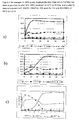
- This figure contains XPS sputter depth profiles obtained for CoCrMo test disks of polished (2a), treated with the conventional passivation method (30% HNO 3 at 54C for 0.5 hr) (2b) and treated with an inventive passivation method (O 2 plasma treatment at 1000 W, 300 mTorr, 250 sccm for 1 hr followed by 30% HNO 3 at 54°C for 0.5 hr) (2c).
- the profile data is displayed with depth (plotted as ⁇ removed) in the X-direction and atomic concentration (AC) in the y-direction.
- the data provides a 3-dimensional picture that shows the elemental composition of the uppermost atomic layers (approximately 10 to 40 nm) of the sample material.
- the top plot Figure 2a shows the XPS sputter depth profile representative of a polished CoCrMo test disk surface.
- the data shows that the topmost surface of this sample contains equal concentrations of Co (x) and Cr ( ⁇ ), or the Cr/Co ratio on the surface is about 1.
- the data further shows the presence of a very thin (approximately 1 nm) surface oxide layer, which is evident from the rapid decline in the oxygen ( ⁇ ) signal.
- the AC composition measured by XPS reflects the bulk stoichiometry of the alloy.
- the XPS depth profile data in Figure 2b shows the surface after conventional treatment. The thickness of the oxide layer is about 2 nm and Cr/Co ratio is about 2.
- the XPS profile collected for the inventive process treated an "ultra-passivated" sample indicates that the passivation process used for this sample produced a much thicker oxide layer. In this instance the relative depth of the oxide layer is approximately 5 nm. More importantly, the data further shows that the composition of the surface oxide layer is predominantly a Chromium oxide, and while not wanting to be bound by theory, is most likely Cr 2 O 3 . Again, this interpretation is based on the elevated concentrations of Cr ( ⁇ ) and O ( ⁇ ) within the uppermost 4 to 5 nm coupled with the fact that the cobalt signal (x) was well below 10 % (atomic) over this same depth range.
- CoCr (F 1537) disks were placed on the centre rack (ground potential) of the plasma chamber.
- the CoCrMo test disks were treated at an RF power setting of 1000 watts for 1 hour. After allowing the samples in the chamber to cool to room temperature, the chamber was backfilled with dry nitrogen and the test disks were removed.
- the plasma modified CoCrMo disks were then immersed in 6N HCl for 1 hr at room temperature. At this stage the surface chemistry of the modified test disk was evaluated using X-ray Photoelectron Spectroscopy (XPS).
- XPS X-ray Photoelectron Spectroscopy
- Figure 4 contains XPS sputter depth profiles obtained for both the polished and the treated with the inventive process samples.
- the inventive process used is O 2 plasma treatment at 1000 W, 300 mTorr, 250 sccm for 1 hr + 6N HCl for 1 hr treatment.
- the top plot ( Figure 4a ) shows the XPS sputter depth profile representative of a polished CoCr test disk surface.
- the data further shows that the composition of the surface oxide layer is predominantly Chromium oxide, most likely Cr 2 O 3 . Again, this interpretation is based on the elevated concentrations of Cr ( ⁇ ) and O ( ⁇ ) within the uppermost 4 to 5 nm coupled with the fact that the cobalt signal (x) was well below 10 % (atomic) over this same depth range
- Figure 5a shows the XPS sputter depth profile of a CoCr test disk that was passivated with the inventive process (02 plasma treatment at 1000 W, 300 mTorr, 250 sccm for 1hr + 6N HCl at room temperature for 1hr).
- inventive process 02 plasma treatment at 1000 W, 300 mTorr, 250 sccm for 1hr + 6N HCl at room temperature for 1hr.
- Figure 6 shows the wear test results from the femur heads treated with the conventional process (30% HNO3 at 60°C for 0.5 hr) and with the inventive process (30% HNO 3 at 60°C for 0.5 hr + O 2 plasma treatment at 1000 W, 300 mTorr, 250 sccm for 1 hr + 30% HNO 3 at 60°C for 0.5 hr) respectively.
- the wear test curves show that the femur head after the inventive treatment reduced 3 folds of wear when compared with the one after the conventional treatment.
- Table 1 shows the ICP-MS (Inductively Coupled Plasma Mass Spectrometry) data (ICP data) that is obtained from the 20 ml 90% bovine serum solution which immersed eight CoCr disks for 7 weeks.
- the disks are 25.4 mm (1 inch) in diameter and 3.18 mm (0.125 inch) in thickness.
- the solution was placed on a shaker in a 37 °C incubator. The result shows that the disks treated with the inventive passivation reduced the total ion release to 26% of that of the disks treated with conventional passivation.
- Table 2 shows ICP-MS (Inductively Coupled Plasma Mass Spectrometry) data obtained from immersing the contacting area of a CoCr stem (size 4) and 32 mm head modular system in a 0.9% saline solution which for 16 days.
- the results show that the implant treated with the inventive passivation reduced the total ion release to 5% of that of the implant treated with the conventional passivation.
Landscapes
- Chemical & Material Sciences (AREA)
- Health & Medical Sciences (AREA)
- Life Sciences & Earth Sciences (AREA)
- Veterinary Medicine (AREA)
- Medicinal Chemistry (AREA)
- Engineering & Computer Science (AREA)
- Organic Chemistry (AREA)
- Public Health (AREA)
- General Health & Medical Sciences (AREA)
- Animal Behavior & Ethology (AREA)
- Mechanical Engineering (AREA)
- Epidemiology (AREA)
- Dermatology (AREA)
- Metallurgy (AREA)
- Transplantation (AREA)
- Oral & Maxillofacial Surgery (AREA)
- Materials Engineering (AREA)
- Chemical Kinetics & Catalysis (AREA)
- Inorganic Chemistry (AREA)
- General Chemical & Material Sciences (AREA)
- Bioinformatics & Cheminformatics (AREA)
- Nuclear Medicine, Radiotherapy & Molecular Imaging (AREA)
- Pharmacology & Pharmacy (AREA)
- Materials For Medical Uses (AREA)
- Physical Vapour Deposition (AREA)
- Crystals, And After-Treatments Of Crystals (AREA)
- Inorganic Insulating Materials (AREA)
- Formation Of Insulating Films (AREA)
- Superconductors And Manufacturing Methods Therefor (AREA)
- Glass Compositions (AREA)
- Coating By Spraying Or Casting (AREA)
Abstract
Description
- This invention relates to a method for treating a chromium containing alloy. Such an alloy might be used in a orthopaedic joint prosthesis.
- Metal-on-metal (MOM) prosthesis implants have been around since the 1960s. Presently, the use of metal-on-metal implants has been increasing due to the fact that historically MOM systems have shown better than two orders of magnitude less wear than metal-on-polyethylene (MOP) systems. However, in the case of MOM devices, there is still concern regarding the long term effects of in vivo metal ion release due to corrosion and/or wear of the metal components.
- The corrosion resistance of chromium containing alloys, for example CoCr and CoCrMo alloys, is thought to be due to the existence of a natural metal oxide layer on the alloy surface. The major components of this oxide layer are cobalt oxide and chromium oxide. Because chromium oxide is much more resistant to leaching by body fluids than cobalt oxide, the corrosion resistance of the alloy depends on the continuity, thickness and chromium oxide content of the layer.
- In the orthopaedic industry, CoCr implants are routinely treated by immersion in 30% nitric acid solution at an elevated temperature (54°C). It is believed by many in the industry that passivating CoCr materials with nitric or citric acid leads to the production of a corrosion resistant surface by forming a thin transparent Chromium oxide film. It is this layer that they believe imparts the corrosion resistance to CoCr implant materials. These beliefs are based on work published for stainless steel passivation. In reality, the surface of a nitric (citric) acid passivated surface has a surface composition of approximately 50:50 Co and Cr.
- MOM implants are also subject to weight loss caused by the continuous friction of two contacted surfaces moving in body fluid. As these surfaces contact each other, the interaction of asperities or surface roughness causes wear.
- To date, most efforts to reduce wear in MOM systems have focussed primarily on reducing surface roughness and/or surface asperities. In particular, many investigators believe that removing surface "carbide asperities" will dramatically reduce break-in wear and yield a lower wear system. Many attempts have been made to remove surface carbides using enhanced polishing methods and heat treatment processes designed to "dissolve" the carbides into the alloy. However, these efforts have produced little impact in terms of a significant reduction in break-in wear. Accordingly, there remains a need to reduce break-in wear in prosthesis devices.
- One aspect of the present invention concerns chromium containing, such as CoCrMo, articles having a surface oxide layer up to 20 nm thick, said surface oxide layer comprising chromium and cobalt oxides where the atomic ratio of Cr/Co is at least about 3. In some aspects, the invention concerns a method comprising: contacting the chromium containing material with a gas plasma under conditions effective to oxidise at least a portion of the material; and contacting the material with an acid under conditions effective to form a robust Chromium oxide surface layer substantially thicker than that produced using the conventional process described above.
- The material can be contacted with the gas plasma before it is contacted with the acid or the material can be contacted with the acid before and after it is contacted with the gas plasma.
- The acid can include nitric acid or hydrochloric acid.
- Preferably, the acid includes hydrochloric acid and the first acid passivation treatment is followed by a second acid passivation treatment using an acid comprising nitric acid.
- The gas plasma used in the methods of the invention can be derived from an oxidative gas or from a mixture of gases comprising oxidative gas and optionally one or more inert gases. One preferred oxidative gas is oxygen. Inert gases include nitrogen, argon and helium. In certain embodiments, the material is contacted with the gas plasma for about 5 to about 120 minutes. In some embodiments, the contacting of the material with the gas plasma is performed at a power of about 100 to about 1000 watts. In some embodiments, the mixture of gasses comprises at least 3 % (v/v) percent oxidative gas. Other embodiments contain 100% (v/v) percent oxidative gas.
- The invention also concerns articles made by the methods of the invention. In some embodiments, the invention concerns articles comprising cobalt and chromium, the article having a surface comprising oxides where the oxides are characterized with a Cr/Co ratio of at least about 3 (as measured by XPS). In certain embodiments, the oxides are characterized by a Cr/Co ratio of about 7. In some articles, the surface oxide is 3 to 8 nm thick. This highly enriched chromium oxide layer impart a significantly higher corrosion resistance versus the relatively thin (for example from about 1 nm to about 2 nm) passive film formed using a conventional passivation process.
- Some articles are designed to be implantable into a mammal. Certain of these articles are joint replacement prosthesis or component thereof. Such prosthesis include hip or knee replacement prosthesis.
- In some embodiments, the treated material is used on a wear surface, especially an orthopaedic implant wear surface to reduce wear.
- Some articles are very corrosion resistant and they can be used in corrosive environment, including acid or alkaline environments. The inventive passivation film can reduce the ion release in simulated body fluid.
- The invention also concerns methods comprising implanting a prosthesis comprising chromium and cobalt in a human or animal body in contact with bone, in which at least a portion of the prosthesis in contact with said bone comprising a surface having an exterior oxide layer of up to 20 nm in thickness that is highly enriched in chromium oxide.
- The present invention provides chromium containing articles and devices having thick and Cr highly enriched surface oxide layers, and processes to make improved wear surfaces on chromium containing materials. This surface preferably has a strengthened passive film, which can reduce ion release rates by decreasing the corrosion rate. Wear is believed to be reduced by protecting the wear surface from selective corrosion in surrounding carbide areas. One type of process according to the invention includes plasma oxidation and acid treatment. The acid treatment can be conducted after plasma oxidation or both before and after plasma oxidation.
- Certain processes involve the steps of subjecting a cobalt- and chromium-containing implant material to an energetic, oxidative gas plasma and treating the implant material with acid. This acid treatment can be achieved after plasma oxidation or before and after plasma oxidation. The plasma treatment process can be achieved using an oxidative gas such as oxygen or a mixture of oxidative gases and inert gases at a power of between 100 and 1000 watts for a time of between 5 minutes to 120 minutes. Compared with the oxide layer obtained from the conventional HNO3 passivation process, the one obtained from the inventive process preferably is thicker and the Cr/Co ratio is higher. The enhancement of the oxide is believed to reduce the amount of metal ion release due to corrosion and/or wear.
- In certain methods of the invention, surfaces are treated with a gas plasma under conditions effective to oxidise at least a portion of the surface. The oxidative component of the gas can comprise oxygen, water, hydrogen peroxide, or mixtures thereof. In some embodiments, the oxidative gas plasma can be formed, for example, from oxygen, a mixture of oxygen with air, or with one of the foregoing along with one or more non-reducible gases. Non-reducible gases include argon, nitrogen, neon, helium, xenon, and krypton. In some embodiments, argon is preferred. In some preferred embodiments, the amount of oxygen in the gas is greater than 3%. In some preferred embodiments, the amount of oxygen in the gas is 3% to 100%
- Typically, a plasma is generated by creating an electrical discharge in a gaseous atmosphere under suitable pressure conditions. A typical plasma treatment system has a chamber capable of being maintained at a desired pressure (typically atmospheric or below). The surface to be treated is placed with the chamber with the selected gas and an appropriate electrical discharge is applied to the chamber. A number of gas plasma treatment systems suitable for use in the practice of the present invention are commercially available and such systems are generally known.
- The energy source used in the gas plasma oxidation is one capable of supplying a sufficient amount of energy to ionise at least a portion of oxidative gas to form a gas plasma. At least three power sources have been widely used in practice to supply the energy. These include DC electrical energy, radio frequency (RF) energy, and microwave energy. In methods of the present invention, any suitable energy source, including the three mentioned above can be used. It is generally recognised, however, that RF energy sources typically have the greatest sensitivity and are the freest from interference. Thus, in some embodiments, a RF energy source is preferred.
- The amount of energy utilized to form the plasma is typically from about 100 to about 1000 watts. In some preferred embodiments, the amount of energy is from about 800 to about 1000 watts.
- The gas plasma treatment of the surface is typically performed for about 5 to about 120 minutes. In some embodiments, the time is from about 30 to about 90 minutes. In other embodiments, however, the time is at least 60 minutes.
- The pressure at which the gas plasma oxidation is performed is typically from atmospheric pressure to sub-atmospheric pressure. In some embodiments, the pressure is from about 200 mTorr to about 400 mTorr. In certain embodiments, the pressure is about 300 mTorr.
- During the gas plasma oxidation, the flow rate of the gases through the oxidizing chamber is generally from about 100 standard cubic centimetres per minute (sccm) to abut 500 sccm. In one preferred embodiment, the flow rate is about 150 to 350 sccm (preferably about 250).
- In some embodiments, the acid includes nitric acid (HNO3), hydrochloric acid (HCl), sulphuric acid (H2SO4) or citric acid. In some embodiments, the preferred acid includes nitric acid and HCl. The surface is preferably contacted with a liquid acid at a concentration that suitably passivates the surface. Preferably, the concentration of the acid is at least about 2M, more preferably at least about 6M. Preferably, the concentration of the acid is not more than about 8M, more preferably not more than about 6M. The surface can be treated for a time sufficient to develop a thick robust Cr rich surface layer. In some embodiments, the surface is contacted with the acid for at least about 20 min, preferably at least about 30 min. In some embodiments, the surface is contacted with the acid for not more than about 120 minutes, preferably not more than about 90 min, for example about 60 min). The treatment can occur at a temperature of at least about 10 °C, preferably at least about 20°C. The treatment can occur at a temperature of not more than about 90°C, preferably not more than about 60°C.
- In some embodiments, more than one acid passivation step can be utilized. The acid passivation step can be conducted after plasma oxidation or conducted before and after plasma oxidation. As used herein, the term "before" includes intervening events that may occur (for example, "before" need not be "immediately before"). Certain embodiments have more than one acid treatment step after the plasma oxidation. For example, an acid treatment step using an acid comprising hydrochloric acid followed by another acid treatment step using nitric acid can be utilized.
- Embodiments of the invention are described below by way of example with reference to the accompanying drawings, in which:
-
Figure 1 shows a typical wear graph for MOM prosthesis devices. The graph is divided into two phased: the initial run-in phase and the second steady state phase. The X-axis is the cycle number and the Y-axis is the accumulative volume loss of the prosthesis. The slope of the graph is the volume loss rate. The graph shows that a majority of the volume loss happens in the initial stage-run-in phase. -
Figure 2 shows XPS sputter depth profile data obtained on CoCrMo test disks:- (a) polished, (b) after 30% HNO3 treatment at 54°C for 0.5 hr (representative of a conventional passivation method), and (c) after O2 plasma treatment with 1000 W, 300 mTorr, 250 sccm for 1 hr + 30% HNO3 at 54°C for 0.5 hr (in accordance with the invention). A treatment in accordance with the invention results in a substantially thicker surface oxide than the conventionally passivated surface (about 5 nm vs 2 nm). In addition, the Cr/Co ratio measured for the surface treated using the inventive process (Cr is dominant and Co is near 0) is also enhanced relative to the conventionally passivated surface (Cr/Co = 0.2).
-
Figure 3 shows the same XPS sputter depth profile data as shown inFigure 2 , but the O and C profile data has been removed and the atomic concentration for the metal atoms has been renormalised: (a) polished, (b) after 30% HNO3 at 54°C for 0.5 hr, (the conventional passive method) and (c) after O2 plasma treatment with 1000 W, 300 mTorr, 250 sccm for 1 hr + 30% HNO3 at 54°C for 0.5 hr (in accordance with the invention). It shows that Cr/Co ratio in the inventive treatment surface oxide film (c) is the highest. -
Figure 4 shows XPS sputter depth profile data obtained on CoCrMo test disks:- (a) polished and (b) after inventive treatment: O2 plasma treatment with 1000 W, 300 mTorr and 250 sccm for 1 hr + 6N HCl treatment for 1hr.
-
Figure 5 shows the XPS sputter depth profile data on the test disks: (a) after 1hr O2 plasma treatment with 1000 W, 300 mTorr and 250 sccm + 1 hr 6N HCl treatment at room temperature, (b) after treated with above method, the surface was put into 6N HCl at 60°C for 0.5 hrs, and (c) after treated with above method, the treated surface was put into 6N NaOH at 60°C for 1 hr. The inventive passive film is corrosion resistant in both acid and alkaline solutions. -
Figure 6 shows Hip simulator wear graph comparing the parts after 3 million cycle wear tests. The one after inventive treatment (30% HNO3, at 54°C for 0.5 hrs + O2 plasma treatment, 1000 W, 300 mTorr, 250 sccm for 1hr + 30% HNO3, at 54°C for 0.5 hrs) is about 3-fold reduction in the break-in wear than the one after the conventional passivation treatment (30% HNO3, at 54°C for 0.5 hrs). The data shows that the ion release on the passivated surface of the invention is significantly reduced. - According to ASTM A380, passivation is the removal of exogenous iron or iron compounds from the surface of stainless steel by means of a chemical dissolution, most typically by a treatment with an acid solution that will remove the surface contamination, but will not significantly affect the stainless steel itself. In addition, it also refers to passivation as the chemical treatment of stainless steel with a mild oxidant, such as a nitric acid solution, for the purpose of enhancing the spontaneous formation of the protective passive film.
- In the context of corrosion, passivation is the spontaneous formation of a nonreactive surface film that inhibits further corrosion. This layer is usually an oxide or nitride that is a few atoms thick.
- In the context of CoCrMo implant materials the XPS sputter depth profile presented in
Figure 2b illustrates the typical surface and near surface composition of a conventionally passivated material, i.e treated in 30% nitric acid solution. - "Ultra passivation" is the inventive process described here in whereby the surface, CoCrMo for example, is first treated in an oxygen plasma followed by an acid treatment. The surface (near surface) chemistry typical for materials treated using this process is shown in
Figure 2c . The inventive passivation process produces a significantly thicker protective surface oxide layer relative to the conventional process (Figure 2b ). - By "surface," in reference to a device or other article, it is intended to mean the outermost region of the device or article. In some cases, the surface of a device or article can have a metal oxide layer up to 20 nm thick. Some devices or articles can have a plurality of surfaces having different composition.
- Surfaces suitable for treatment with the methods of the instant invention include those that are found on implantable devices (such as knee and hip replacement prostheses) and/or otherwise contain cobalt and chromium. Some metal implants are fabricated from surgical grade cobalt-chromium-molybdenum (CoCrMo) alloys because these alloys show good corrosion and wear resistance.
- At various points in the processes of the instant invention, the substrate surface can optionally be cleaned using typical usual cleaning procedures, such as degreasing with detergent or an alkaline solution. Ultrasonic cleaning in detergent, followed by ultrasonic cleaning in water and drying, may degrease the substrate surface. In some embodiments, the entire implant is cleaned. In other embodiments, only a portion of the implant will be cleaned. One skilled in the art will readily appreciate that there may be a desire to perform an initial cleaning step before treating the surface with the processes of the invention. It may be desirable to clean the surface between steps of the processes and/or at the end of the passivation processes. Some cleaning steps might involve rinsing with soaking in water and followed by drying the surface.
- The primary action of this treatment process is to impart a higher/improved corrosion resistance to the CoCr materials. The improved corrosion resistance results from the formation of a strengthened oxide layer with a high Cr/Co ratio on the device surface. While not wanting to be bound by theory, we believe that the enhanced corrosion resistance also leads to lower wear and/or metal ion release. We further feel that this treatment process should also improve the overall corrosion resistance of CoCr materials used in other applications. This benefit would include non-articulating surfaces as well as metal on poly or metal on ceramic applications.
- Except where noted, all tests were conducted on the ASTM F-1537 CoCrMo polished disks. The finished disks were 2 mm thick and 25 mm in diameter. The surface of the disks was polished to a mirror finish (0.1 µm) then rigorously cleaned in an Alconox solution in an ultrasonic bath. This step was followed with two successive 3 minute reverse osmosis (RO) water rinse treatments.
- Plasma treatments were performed in a PVA TePla Model 7200 Plasma Processing System by placing the sample CoCr disks in an aluminum tray located in the centre of the chamber. Power settings for the plasma treatments were variable between 100 and 1000 watts. The examples presented here were conducted at 1000 watts (W), but 500 w and 800 w were also found to yield similar results. After placing sample disks into the plasma system, the chamber was evacuated to approximately 30 mTorr. After the chamber was evacuated, oxygen was introduced into the chamber to 300 mTorr with a flow rate of 250 sccm. The treatment time used in the examples was 1 hour. The operation of the plasma treatment process was conducted under computer control, which included establishing and maintaining the process gas treatment "recipe".
- X-ray photoelectron spectroscopy (XPS) data was acquired using a Physical Electronics (PHI) Quantara SXM instrument. The system uses a monochromatic AlKα x-ray source that emits photons at 1486.6 eV. The anode was run at a power of 45 watts (15 KeV). The typical base vacuum inside the spectrometer was 5 × 10⁻⁹ torr. The analysis area for the XPS depth profile acquisitions was set at 200 µm. Sputtering for the XPS depth profiling was accomplished using energetic (2.0 keV) Ar ions rastered over a 2 × 2 mm area. The XPS depth profile data presented here is shown relative to depth quoted in Angstroms (Å). The sputter rate was determined using a 1000 Å SiO2/Si calibration standard. The depth profile is displayed as atomic concentration (AC) versus sputter depth in Angstroms (Å). The sputter depth values in the graphs are calculated by multiplying the calibrated sputter rate (discussed above) and the sputter time. The AC values represent a normalized elemental atomic composition for each of the species listed. The numbers are calculated based on the XPS peak area and corrected with standard calibration factors resident in the data analysis software provided by the vendor.
- Clean and polished 25 mm diameter CoCrMo (F 1537) disks were placed on the centre rack of the plasma chamber. The plasma chamber was evacuated to a base pressure of 30 mTorr then backfilled to 300 mTorr with O2 (flow rate = 250 sccm). The CoCr test disks were treated at an RF power setting of 1000 watts for 1 hour. After allowing the samples in the chamber to cool to room temperature, the chamber was backfilled with dry-N2 and the test disks were removed. The plasma modified CoCrMo disks were then submitted for passivation using 30% HNO3 for 30 minutes at a temperature of 54°C. At this stage the surface chemistry of the modified test disks was evaluated using X-ray Photoelectron Spectroscopy (XPS). More specifically, the XPS analyses were conducted as sputter depth profiles, which entail interleaving argon (Ar) ion sputtering with XPS analyses. The Ar ion sputtering interacts with the topmost surface atoms causing them to be removed at controllable rate. In the present analysis the sputter removal rate was calculated to be approximately 80 Å.min-1 relative to the SiO2 standard. The resulting depth profile data obtained for the modified test disks is shown in
Figure 2 . This figure contains XPS sputter depth profiles obtained for CoCrMo test disks of polished (2a), treated with the conventional passivation method (30% HNO3 at 54C for 0.5 hr) (2b) and treated with an inventive passivation method (O2 plasma treatment at 1000 W, 300 mTorr, 250 sccm for 1 hr followed by 30% HNO3 at 54°C for 0.5 hr) (2c). The profile data is displayed with depth (plotted as Å removed) in the X-direction and atomic concentration (AC) in the y-direction. The data provides a 3-dimensional picture that shows the elemental composition of the uppermost atomic layers (approximately 10 to 40 nm) of the sample material. The top plotFigure 2a shows the XPS sputter depth profile representative of a polished CoCrMo test disk surface. The data shows that the topmost surface of this sample contains equal concentrations of Co (x) and Cr (▲), or the Cr/Co ratio on the surface is about 1. The data further shows the presence of a very thin (approximately 1 nm) surface oxide layer, which is evident from the rapid decline in the oxygen (■) signal. At a depth of about 2 nm, the AC composition measured by XPS reflects the bulk stoichiometry of the alloy. The XPS depth profile data inFigure 2b shows the surface after conventional treatment. The thickness of the oxide layer is about 2 nm and Cr/Co ratio is about 2. The XPS profile collected for the inventive process treated an "ultra-passivated" sample (Figure 2c ) indicates that the passivation process used for this sample produced a much thicker oxide layer. In this instance the relative depth of the oxide layer is approximately 5 nm. More importantly, the data further shows that the composition of the surface oxide layer is predominantly a Chromium oxide, and while not wanting to be bound by theory, is most likely Cr2O3. Again, this interpretation is based on the elevated concentrations of Cr (▲) and O (■) within the uppermost 4 to 5 nm coupled with the fact that the cobalt signal (x) was well below 10 % (atomic) over this same depth range. - The same three XPS sputter depth profiles previously shown in
Figure 2 are reproduced inFigure 3 , but in this case the O and C traces have been removed and the metal AC values renormalised. This figure is included to more accurately illustrate how the inventive "ultra-passivation" process alters the metal atom composition of the near surface region. This figure clearly illustrates the fact that the natural oxide layer on the polished CoCr material (Figure 3a ) is thin and has only a slight enhancement of Cr in it; conventional passivation increases the oxide thickness and Cr/Co ratio in the oxide layer (Figure 3b ), and the "ultra-passivated" (Figure3c) has the thickest oxide layer and the highest Cr/Cr ratio in the outer 4 nm of the sample. - Clean and polished 25mm diameter CoCr (F 1537) disks were placed on the centre rack (ground potential) of the plasma chamber. The plasma chamber was evacuated to a base pressure of 30 mTorr then backfilled to 300mTorr with O2 (flow rate = 250 sccm). The CoCrMo test disks were treated at an RF power setting of 1000 watts for 1 hour. After allowing the samples in the chamber to cool to room temperature, the chamber was backfilled with dry nitrogen and the test disks were removed. The plasma modified CoCrMo disks were then immersed in 6N HCl for 1 hr at room temperature. At this stage the surface chemistry of the modified test disk was evaluated using X-ray Photoelectron Spectroscopy (XPS). More specifically, the XPS analyses were conducted as sputter depth profiles. In the present analysis the sputter removal rate was calculated to be approximately 80 Å.min-1 relative to the SiO2 standard. The resulting depth profile data obtained for the modified test disks is shown in
Figure 4. Figure 4 contains XPS sputter depth profiles obtained for both the polished and the treated with the inventive process samples. In this example, the inventive process used is O2 plasma treatment at 1000 W, 300 mTorr, 250 sccm for 1 hr + 6N HCl for 1 hr treatment. The top plot (Figure 4a ) shows the XPS sputter depth profile representative of a polished CoCr test disk surface. This data shows that the topmost surface of this sample contains approximately equal concentrations of Co (x) and Cr (▲). The data further shows the presence of a very thin (approximately 10 Å) surface oxide layer, which is evident from the rapid decline in the oxygen (■) signal. At a depth of about 20 Å, the AC composition measured by XPS reflects the bulk stoichiometry of the alloy. In contrast to the data obtained for the polished sample shown inFigure 4a , the XPS profile collected for an "ultra-passivated" sample treated with the inventive process (Figure 4b ) indicates that the passivation process used for this sample produced a much thicker oxide layer. In this instance the relative depth of the oxide layer is approximately 5 nm. More importantly, the data further shows that the composition of the surface oxide layer is predominantly Chromium oxide, most likely Cr2O3. Again, this interpretation is based on the elevated concentrations of Cr (▲) and O (■) within the uppermost 4 to 5 nm coupled with the fact that the cobalt signal (x) was well below 10 % (atomic) over this same depth range - A further proof of the enhanced corrosion resistance of the material after "ultra-passivated" inventive process treatment:
Figure 5a shows the XPS sputter depth profile of a CoCr test disk that was passivated with the inventive process (02 plasma treatment at 1000 W, 300 mTorr, 250 sccm for 1hr + 6N HCl at room temperature for 1hr). After above treated sample was put into 6N HCl at 60°C for 0.5 hr (Figure 5b ) or 6N NaOH for 1 hr (Figure 5c ), the oxide film on the surface has no significant change. Thus, the CoCrMo surface after the inventive treatment can stand corrosive environment. -
Figure 6 shows the wear test results from the femur heads treated with the conventional process (30% HNO3 at 60°C for 0.5 hr) and with the inventive process (30% HNO3 at 60°C for 0.5 hr + O2 plasma treatment at 1000 W, 300 mTorr, 250 sccm for 1 hr + 30% HNO3 at 60°C for 0.5 hr) respectively. The wear test curves show that the femur head after the inventive treatment reduced 3 folds of wear when compared with the one after the conventional treatment. - Table 1 shows the ICP-MS (Inductively Coupled Plasma Mass Spectrometry) data (ICP data) that is obtained from the 20
ml 90% bovine serum solution which immersed eight CoCr disks for 7 weeks. The disks are 25.4 mm (1 inch) in diameter and 3.18 mm (0.125 inch) in thickness. The solution was placed on a shaker in a 37 °C incubator. The result shows that the disks treated with the inventive passivation reduced the total ion release to 26% of that of the disks treated with conventional passivation.Table 1: Effect of passivation technique on ion release from CoCr disks Sample Co (g) Cr (g) Cr (g) Total (g) After conventional passivation (CP) 0.116 0.014 0.018 0.148 After passivation according to the invention (IP) 0.017 0.007 0.015 0.039 IP/CP (%) 15 50 83 26 - Table 2 shows ICP-MS (Inductively Coupled Plasma Mass Spectrometry) data obtained from immersing the contacting area of a CoCr stem (size 4) and 32 mm head modular system in a 0.9% saline solution which for 16 days. The results show that the implant treated with the inventive passivation reduced the total ion release to 5% of that of the implant treated with the conventional passivation.
Table 2: Comparison of ion release from CoCr implants Sample Co (µg.ml-1) Cr (µg.ml-1) Cr (µg.ml-1) Total After conventional passivation (CP) 0.010 0.200 ND 0.210 After passivation according to the invention (IP) 0.004 0.008 ND 0.012 IP/CP (%) 40 4 6
Claims (9)
- A method of treating a chromium containing material, the method comprising contacting the material with a gas plasma under conditions effective to oxidise at least a portion of the material, and contacting the material with an acid.
- The method of claim 1, in which the material is contacted with the gas plasma before it is contacted with the acid.
- The method of claim 1, in which the material is contacted with the acid both before and after the material is contacted with the gas plasma.
- The method of claim 1, in which the acid includes at least one of nitric acid and hydrochloric acid.
- The method of claim 4, in which contacting the material with a acid utilizes an acid concentration of 2 to 8 M, for 20 min to 2 hr, at a temperature of 0°C to 90°C.
- The method of claim 1, in which the gas plasma is derived from a gas comprising oxygen and optionally at least one of helium and argon.
- A chromium containing article having a surface oxide layer up to 20 nm thick, the surface oxide layer comprising chromium and cobalt oxides where the atomic ratio of Cr/Co more than 3.
- The article of claim 7, in which the surface oxide is from 2.5 to 8 nm thick and in which the Cr/Co atomic ratio is from 3 to 7.
- The article of claim 7, in which the article is a joint replacement prosthesis or component thereof.
Applications Claiming Priority (1)
| Application Number | Priority Date | Filing Date | Title |
|---|---|---|---|
| US95677807P | 2007-08-20 | 2007-08-20 |
Publications (2)
| Publication Number | Publication Date |
|---|---|
| EP2072629A1 true EP2072629A1 (en) | 2009-06-24 |
| EP2072629B1 EP2072629B1 (en) | 2010-10-06 |
Family
ID=40456604
Family Applications (1)
| Application Number | Title | Priority Date | Filing Date |
|---|---|---|---|
| EP08162563A Not-in-force EP2072629B1 (en) | 2007-08-20 | 2008-08-18 | Ultra-passivation of chromium-containing alloy |
Country Status (10)
| Country | Link |
|---|---|
| US (2) | US8153015B2 (en) |
| EP (1) | EP2072629B1 (en) |
| JP (1) | JP2009101132A (en) |
| CN (1) | CN101392373A (en) |
| AT (1) | ATE483828T1 (en) |
| AU (1) | AU2008207373B2 (en) |
| DE (1) | DE602008002889D1 (en) |
| DK (1) | DK2072629T3 (en) |
| ES (1) | ES2350966T3 (en) |
| ZA (1) | ZA200807163B (en) |
Cited By (2)
| Publication number | Priority date | Publication date | Assignee | Title |
|---|---|---|---|---|
| EP2113260A1 (en) * | 2008-04-28 | 2009-11-04 | DePuy Products, Inc. | Implant surfaces and treatments for wear reduction |
| US8475536B2 (en) | 2010-01-29 | 2013-07-02 | DePuy Synthes Products, LLC | Methods and devices for implants with improved cement adhesion |
Families Citing this family (8)
| Publication number | Priority date | Publication date | Assignee | Title |
|---|---|---|---|---|
| EP2072629B1 (en) * | 2007-08-20 | 2010-10-06 | DePuy Products, Inc. | Ultra-passivation of chromium-containing alloy |
| US20100268227A1 (en) * | 2009-04-15 | 2010-10-21 | Depuy Products, Inc. | Methods and Devices for Bone Attachment |
| US8696759B2 (en) | 2009-04-15 | 2014-04-15 | DePuy Synthes Products, LLC | Methods and devices for implants with calcium phosphate |
| AU2010201402C1 (en) * | 2009-04-15 | 2014-10-16 | Depuy Products, Inc. | Nanotextured cobalt-chromium alloy articles having high wettability and method of producing same |
| JP5636658B2 (en) * | 2009-09-30 | 2014-12-10 | 凸版印刷株式会社 | Photomask and photomask manufacturing method |
| US9903020B2 (en) | 2014-03-31 | 2018-02-27 | Applied Materials, Inc. | Generation of compact alumina passivation layers on aluminum plasma equipment components |
| US20160225652A1 (en) | 2015-02-03 | 2016-08-04 | Applied Materials, Inc. | Low temperature chuck for plasma processing systems |
| US10399166B2 (en) | 2015-10-30 | 2019-09-03 | General Electric Company | System and method for machining workpiece of lattice structure and article machined therefrom |
Citations (3)
| Publication number | Priority date | Publication date | Assignee | Title |
|---|---|---|---|---|
| EP0520721A2 (en) * | 1991-06-24 | 1992-12-30 | Smith & Nephew Richards, Inc. | Passivation method and passivated implant |
| WO2008018820A1 (en) * | 2006-08-10 | 2008-02-14 | St. Jude Medical Ab | Passivated metal conductors for use in cardiac leads and method of prepararing the same |
| EP2002854A2 (en) | 2006-03-29 | 2008-12-17 | Japan Medical Materials Corporations | Biomaterial, artificial joint using the same and method of producing the same |
Family Cites Families (13)
| Publication number | Priority date | Publication date | Assignee | Title |
|---|---|---|---|---|
| US4421593A (en) * | 1983-04-11 | 1983-12-20 | Rca Corporation | Reverse etching of chromium |
| US4908069A (en) * | 1987-10-19 | 1990-03-13 | Sps Technologies, Inc. | Alloys containing gamma prime phase and process for forming same |
| FI953472A0 (en) * | 1993-01-19 | 1995-07-18 | Schneider Usa Inc | Coated, combined tension frame |
| JP3312585B2 (en) * | 1997-11-14 | 2002-08-12 | 三菱マテリアル株式会社 | Valve seat made of Fe-based sintered alloy with excellent wear resistance |
| JP2005538745A (en) * | 2001-12-06 | 2005-12-22 | スミス アンド ネフュー インコーポレーテッド | In-situ oxidized textured surface for prosthetic devices and method of manufacturing the same |
| GB0209797D0 (en) * | 2002-04-29 | 2002-06-05 | Univ Birmingham | Method of surface hardening cobalt-chromium based alloy articles |
| US7520947B2 (en) * | 2003-05-23 | 2009-04-21 | Ati Properties, Inc. | Cobalt alloys, methods of making cobalt alloys, and implants and articles of manufacture made therefrom |
| US8048369B2 (en) * | 2003-09-05 | 2011-11-01 | Ati Properties, Inc. | Cobalt-nickel-chromium-molybdenum alloys with reduced level of titanium nitride inclusions |
| WO2005047559A1 (en) * | 2003-11-13 | 2005-05-26 | Lifenova Biomedical, S.A. | Method of producing endosseous implants or medical prostheses by means of ionic implantation, and endosseous implant or medical prosthesis thus produced |
| DE602005027440D1 (en) * | 2004-01-19 | 2011-05-26 | Univ South Australia | BIOACTIVE COATING OF BIOMEDICAL IMPLANTS |
| ATE485845T1 (en) * | 2005-01-13 | 2010-11-15 | Versitech Ltd | SURFACE TREATED MOLD MEMORY MATERIALS AND PRODUCTION METHOD THEREOF |
| EP2072629B1 (en) * | 2007-08-20 | 2010-10-06 | DePuy Products, Inc. | Ultra-passivation of chromium-containing alloy |
| US20090204213A1 (en) * | 2008-02-13 | 2009-08-13 | Depuy Products, Inc. | Metallic implants |
-
2008
- 2008-08-18 EP EP08162563A patent/EP2072629B1/en not_active Not-in-force
- 2008-08-18 ES ES08162563T patent/ES2350966T3/en active Active
- 2008-08-18 US US12/193,092 patent/US8153015B2/en active Active
- 2008-08-18 DK DK08162563.4T patent/DK2072629T3/en active
- 2008-08-18 DE DE602008002889T patent/DE602008002889D1/en active Active
- 2008-08-18 AU AU2008207373A patent/AU2008207373B2/en not_active Ceased
- 2008-08-18 AT AT08162563T patent/ATE483828T1/en active
- 2008-08-19 ZA ZA200807163A patent/ZA200807163B/en unknown
- 2008-08-19 JP JP2008210345A patent/JP2009101132A/en not_active Abandoned
- 2008-08-20 CN CNA200810168647XA patent/CN101392373A/en active Pending
-
2012
- 2012-03-05 US US13/411,931 patent/US20120239157A1/en not_active Abandoned
Patent Citations (3)
| Publication number | Priority date | Publication date | Assignee | Title |
|---|---|---|---|---|
| EP0520721A2 (en) * | 1991-06-24 | 1992-12-30 | Smith & Nephew Richards, Inc. | Passivation method and passivated implant |
| EP2002854A2 (en) | 2006-03-29 | 2008-12-17 | Japan Medical Materials Corporations | Biomaterial, artificial joint using the same and method of producing the same |
| WO2008018820A1 (en) * | 2006-08-10 | 2008-02-14 | St. Jude Medical Ab | Passivated metal conductors for use in cardiac leads and method of prepararing the same |
Cited By (2)
| Publication number | Priority date | Publication date | Assignee | Title |
|---|---|---|---|---|
| EP2113260A1 (en) * | 2008-04-28 | 2009-11-04 | DePuy Products, Inc. | Implant surfaces and treatments for wear reduction |
| US8475536B2 (en) | 2010-01-29 | 2013-07-02 | DePuy Synthes Products, LLC | Methods and devices for implants with improved cement adhesion |
Also Published As
| Publication number | Publication date |
|---|---|
| AU2008207373B2 (en) | 2012-09-20 |
| ZA200807163B (en) | 2010-07-28 |
| ES2350966T3 (en) | 2011-01-28 |
| US20120239157A1 (en) | 2012-09-20 |
| AU2008207373A1 (en) | 2009-03-12 |
| EP2072629B1 (en) | 2010-10-06 |
| DE602008002889D1 (en) | 2010-11-18 |
| CN101392373A (en) | 2009-03-25 |
| DK2072629T3 (en) | 2011-01-17 |
| US8153015B2 (en) | 2012-04-10 |
| US20090175918A1 (en) | 2009-07-09 |
| JP2009101132A (en) | 2009-05-14 |
| ATE483828T1 (en) | 2010-10-15 |
Similar Documents
| Publication | Publication Date | Title |
|---|---|---|
| EP2072629B1 (en) | Ultra-passivation of chromium-containing alloy | |
| US5334264A (en) | Titanium plasma nitriding intensified by thermionic emission source | |
| Ueda et al. | Improvement of tribological properties of Ti6Al4V by nitrogen plasma immersion ion implantation | |
| EP1477141B1 (en) | Surface treatment process for implants made of titanium alloy | |
| Trigwell et al. | Effects of surface treatment on the surface chemistry of NiTi alloy for biomedical applications | |
| Shanaghi et al. | Structure and corrosion resistance of Ti/TiC coatings fabricated by plasma immersion ion implantation and deposition on nickel–titanium | |
| El-Hossary et al. | Tribo-mechanical and electrochemical properties of plasma nitriding titanium | |
| JPH06507210A (en) | Surface treatment and deposition method for forming titanium nitride on carbonaceous materials | |
| JPH0565621A (en) | Process for producing titanium or titanium alloy orthopedic implant and process for surface hardening of same | |
| WO1997036018A1 (en) | Titanium or titanium alloy member and surface treatment method therefor | |
| Poon et al. | Anti-corrosion performance of oxidized and oxygen plasma-implanted NiTi alloys | |
| Catanio Bortolan et al. | Plasma-immersion ion implantation surface oxidation on a cobalt-chromium alloy for biomedical applications | |
| Cheng et al. | Surface modification of TiNi alloy through tantalum immersion ion implantation | |
| Wan et al. | Corrosion properties of oxygen plasma immersion ion implantation treated magnesium | |
| Paredes et al. | Comparative study of surface chemical composition and oxide layer modification upon oxygen plasma cleaning and piranha etching on a novel low elastic modulus Ti25Nb21Hf alloy | |
| EP2113260A1 (en) | Implant surfaces and treatments for wear reduction | |
| JP2001097791A (en) | Corrosionproof member and method for producing the same | |
| EP2392357B1 (en) | Bone-repairing material and method for producing the same | |
| US20180291523A1 (en) | Development of a passivated stainless steel surface | |
| Poon et al. | Improvement on corrosion resistance of NiTi orthopedic materials by carbon plasma immersion ion implantation | |
| Kashin et al. | Influence of surface modification of nitinol with silicon using plasma-immersion ion implantation on the alloy corrosion resistance in artificial physiological solutions | |
| Milić et al. | The influence of the physicochemical characteristics of the substrate surface on the deposited TiN film properties | |
| Kapczinski et al. | Near-surface composition and tribological behaviour of plasma nitrided titanium | |
| Kaewnisai et al. | Effect of pulse frequency on the surface properties and corrosion resistance of a plasma-nitrided Ti-6Al-4V alloy | |
| Lotkov et al. | Effect of plasma immersion ion beam processing on the structure–phase state and the properties of the surface layers in titanium nickelide samples |
Legal Events
| Date | Code | Title | Description |
|---|---|---|---|
| PUAI | Public reference made under article 153(3) epc to a published international application that has entered the european phase |
Free format text: ORIGINAL CODE: 0009012 |
|
| AK | Designated contracting states |
Kind code of ref document: A1 Designated state(s): AT BE BG CH CY CZ DE DK EE ES FI FR GB GR HR HU IE IS IT LI LT LU LV MC MT NL NO PL PT RO SE SI SK TR |
|
| AX | Request for extension of the european patent |
Extension state: AL BA MK RS |
|
| 17P | Request for examination filed |
Effective date: 20090616 |
|
| 17Q | First examination report despatched |
Effective date: 20090805 |
|
| AKX | Designation fees paid |
Designated state(s): AT BE BG CH CY CZ DE DK EE ES FI FR GB GR HR HU IE IS IT LI LT LU LV MC MT NL NO PL PT RO SE SI SK TR |
|
| GRAP | Despatch of communication of intention to grant a patent |
Free format text: ORIGINAL CODE: EPIDOSNIGR1 |
|
| GRAS | Grant fee paid |
Free format text: ORIGINAL CODE: EPIDOSNIGR3 |
|
| GRAA | (expected) grant |
Free format text: ORIGINAL CODE: 0009210 |
|
| AK | Designated contracting states |
Kind code of ref document: B1 Designated state(s): AT BE BG CH CY CZ DE DK EE ES FI FR GB GR HR HU IE IS IT LI LT LU LV MC MT NL NO PL PT RO SE SI SK TR |
|
| REG | Reference to a national code |
Ref country code: GB Ref legal event code: FG4D |
|
| REG | Reference to a national code |
Ref country code: CH Ref legal event code: EP |
|
| REG | Reference to a national code |
Ref country code: CH Ref legal event code: NV Representative=s name: E. BLUM & CO. AG PATENT- UND MARKENANWAELTE VSP |
|
| REG | Reference to a national code |
Ref country code: IE Ref legal event code: FG4D |
|
| REF | Corresponds to: |
Ref document number: 602008002889 Country of ref document: DE Date of ref document: 20101118 Kind code of ref document: P |
|
| REG | Reference to a national code |
Ref country code: DK Ref legal event code: T3 |
|
| REG | Reference to a national code |
Ref country code: NL Ref legal event code: T3 |
|
| REG | Reference to a national code |
Ref country code: ES Ref legal event code: FG2A Effective date: 20110118 |
|
| REG | Reference to a national code |
Ref country code: SE Ref legal event code: TRGR |
|
| PG25 | Lapsed in a contracting state [announced via postgrant information from national office to epo] |
Ref country code: SI Free format text: LAPSE BECAUSE OF FAILURE TO SUBMIT A TRANSLATION OF THE DESCRIPTION OR TO PAY THE FEE WITHIN THE PRESCRIBED TIME-LIMIT Effective date: 20101006 |
|
| LTIE | Lt: invalidation of european patent or patent extension |
Effective date: 20101006 |
|
| PG25 | Lapsed in a contracting state [announced via postgrant information from national office to epo] |
Ref country code: NO Free format text: LAPSE BECAUSE OF FAILURE TO SUBMIT A TRANSLATION OF THE DESCRIPTION OR TO PAY THE FEE WITHIN THE PRESCRIBED TIME-LIMIT Effective date: 20110106 Ref country code: LT Free format text: LAPSE BECAUSE OF FAILURE TO SUBMIT A TRANSLATION OF THE DESCRIPTION OR TO PAY THE FEE WITHIN THE PRESCRIBED TIME-LIMIT Effective date: 20101006 |
|
| PG25 | Lapsed in a contracting state [announced via postgrant information from national office to epo] |
Ref country code: BG Free format text: LAPSE BECAUSE OF FAILURE TO SUBMIT A TRANSLATION OF THE DESCRIPTION OR TO PAY THE FEE WITHIN THE PRESCRIBED TIME-LIMIT Effective date: 20110106 Ref country code: HR Free format text: LAPSE BECAUSE OF FAILURE TO SUBMIT A TRANSLATION OF THE DESCRIPTION OR TO PAY THE FEE WITHIN THE PRESCRIBED TIME-LIMIT Effective date: 20101006 Ref country code: PT Free format text: LAPSE BECAUSE OF FAILURE TO SUBMIT A TRANSLATION OF THE DESCRIPTION OR TO PAY THE FEE WITHIN THE PRESCRIBED TIME-LIMIT Effective date: 20110207 Ref country code: IS Free format text: LAPSE BECAUSE OF FAILURE TO SUBMIT A TRANSLATION OF THE DESCRIPTION OR TO PAY THE FEE WITHIN THE PRESCRIBED TIME-LIMIT Effective date: 20110206 Ref country code: LV Free format text: LAPSE BECAUSE OF FAILURE TO SUBMIT A TRANSLATION OF THE DESCRIPTION OR TO PAY THE FEE WITHIN THE PRESCRIBED TIME-LIMIT Effective date: 20101006 |
|
| PG25 | Lapsed in a contracting state [announced via postgrant information from national office to epo] |
Ref country code: GR Free format text: LAPSE BECAUSE OF FAILURE TO SUBMIT A TRANSLATION OF THE DESCRIPTION OR TO PAY THE FEE WITHIN THE PRESCRIBED TIME-LIMIT Effective date: 20110107 |
|
| PG25 | Lapsed in a contracting state [announced via postgrant information from national office to epo] |
Ref country code: EE Free format text: LAPSE BECAUSE OF FAILURE TO SUBMIT A TRANSLATION OF THE DESCRIPTION OR TO PAY THE FEE WITHIN THE PRESCRIBED TIME-LIMIT Effective date: 20101006 Ref country code: CZ Free format text: LAPSE BECAUSE OF FAILURE TO SUBMIT A TRANSLATION OF THE DESCRIPTION OR TO PAY THE FEE WITHIN THE PRESCRIBED TIME-LIMIT Effective date: 20101006 |
|
| PLBE | No opposition filed within time limit |
Free format text: ORIGINAL CODE: 0009261 |
|
| STAA | Information on the status of an ep patent application or granted ep patent |
Free format text: STATUS: NO OPPOSITION FILED WITHIN TIME LIMIT |
|
| PG25 | Lapsed in a contracting state [announced via postgrant information from national office to epo] |
Ref country code: PL Free format text: LAPSE BECAUSE OF FAILURE TO SUBMIT A TRANSLATION OF THE DESCRIPTION OR TO PAY THE FEE WITHIN THE PRESCRIBED TIME-LIMIT Effective date: 20101006 Ref country code: SK Free format text: LAPSE BECAUSE OF FAILURE TO SUBMIT A TRANSLATION OF THE DESCRIPTION OR TO PAY THE FEE WITHIN THE PRESCRIBED TIME-LIMIT Effective date: 20101006 Ref country code: RO Free format text: LAPSE BECAUSE OF FAILURE TO SUBMIT A TRANSLATION OF THE DESCRIPTION OR TO PAY THE FEE WITHIN THE PRESCRIBED TIME-LIMIT Effective date: 20101006 |
|
| 26N | No opposition filed |
Effective date: 20110707 |
|
| PGFP | Annual fee paid to national office [announced via postgrant information from national office to epo] |
Ref country code: DK Payment date: 20110810 Year of fee payment: 4 |
|
| REG | Reference to a national code |
Ref country code: DE Ref legal event code: R097 Ref document number: 602008002889 Country of ref document: DE Effective date: 20110707 |
|
| PG25 | Lapsed in a contracting state [announced via postgrant information from national office to epo] |
Ref country code: MT Free format text: LAPSE BECAUSE OF FAILURE TO SUBMIT A TRANSLATION OF THE DESCRIPTION OR TO PAY THE FEE WITHIN THE PRESCRIBED TIME-LIMIT Effective date: 20101006 |
|
| PG25 | Lapsed in a contracting state [announced via postgrant information from national office to epo] |
Ref country code: MC Free format text: LAPSE BECAUSE OF NON-PAYMENT OF DUE FEES Effective date: 20110831 |
|
| PGFP | Annual fee paid to national office [announced via postgrant information from national office to epo] |
Ref country code: SE Payment date: 20120813 Year of fee payment: 5 Ref country code: GB Payment date: 20120815 Year of fee payment: 5 Ref country code: FI Payment date: 20120810 Year of fee payment: 5 Ref country code: IE Payment date: 20120810 Year of fee payment: 5 |
|
| PGFP | Annual fee paid to national office [announced via postgrant information from national office to epo] |
Ref country code: BE Payment date: 20120820 Year of fee payment: 5 Ref country code: ES Payment date: 20120907 Year of fee payment: 5 Ref country code: FR Payment date: 20120823 Year of fee payment: 5 Ref country code: IT Payment date: 20120810 Year of fee payment: 5 Ref country code: DE Payment date: 20120816 Year of fee payment: 5 |
|
| PGFP | Annual fee paid to national office [announced via postgrant information from national office to epo] |
Ref country code: NL Payment date: 20120809 Year of fee payment: 5 |
|
| PG25 | Lapsed in a contracting state [announced via postgrant information from national office to epo] |
Ref country code: CY Free format text: LAPSE BECAUSE OF EXPIRATION OF PROTECTION Effective date: 20101006 Ref country code: LU Free format text: LAPSE BECAUSE OF NON-PAYMENT OF DUE FEES Effective date: 20110818 |
|
| PG25 | Lapsed in a contracting state [announced via postgrant information from national office to epo] |
Ref country code: TR Free format text: LAPSE BECAUSE OF FAILURE TO SUBMIT A TRANSLATION OF THE DESCRIPTION OR TO PAY THE FEE WITHIN THE PRESCRIBED TIME-LIMIT Effective date: 20101006 |
|
| PG25 | Lapsed in a contracting state [announced via postgrant information from national office to epo] |
Ref country code: HU Free format text: LAPSE BECAUSE OF FAILURE TO SUBMIT A TRANSLATION OF THE DESCRIPTION OR TO PAY THE FEE WITHIN THE PRESCRIBED TIME-LIMIT Effective date: 20101006 |
|
| BERE | Be: lapsed |
Owner name: DEPUY PRODUCTS, INC. Effective date: 20130831 |
|
| REG | Reference to a national code |
Ref country code: NL Ref legal event code: V1 Effective date: 20140301 |
|
| REG | Reference to a national code |
Ref country code: DK Ref legal event code: EBP Effective date: 20130831 Ref country code: CH Ref legal event code: PL |
|
| REG | Reference to a national code |
Ref country code: SE Ref legal event code: EUG |
|
| GBPC | Gb: european patent ceased through non-payment of renewal fee |
Effective date: 20130818 |
|
| PG25 | Lapsed in a contracting state [announced via postgrant information from national office to epo] |
Ref country code: NL Free format text: LAPSE BECAUSE OF NON-PAYMENT OF DUE FEES Effective date: 20140301 Ref country code: FI Free format text: LAPSE BECAUSE OF NON-PAYMENT OF DUE FEES Effective date: 20130818 Ref country code: CH Free format text: LAPSE BECAUSE OF NON-PAYMENT OF DUE FEES Effective date: 20130831 Ref country code: LI Free format text: LAPSE BECAUSE OF NON-PAYMENT OF DUE FEES Effective date: 20130831 Ref country code: SE Free format text: LAPSE BECAUSE OF NON-PAYMENT OF DUE FEES Effective date: 20130819 Ref country code: DE Free format text: LAPSE BECAUSE OF NON-PAYMENT OF DUE FEES Effective date: 20140301 |
|
| REG | Reference to a national code |
Ref country code: IE Ref legal event code: MM4A |
|
| REG | Reference to a national code |
Ref country code: DE Ref legal event code: R119 Ref document number: 602008002889 Country of ref document: DE Effective date: 20140301 |
|
| REG | Reference to a national code |
Ref country code: FR Ref legal event code: ST Effective date: 20140430 |
|
| PG25 | Lapsed in a contracting state [announced via postgrant information from national office to epo] |
Ref country code: IT Free format text: LAPSE BECAUSE OF NON-PAYMENT OF DUE FEES Effective date: 20130818 Ref country code: BE Free format text: LAPSE BECAUSE OF NON-PAYMENT OF DUE FEES Effective date: 20130831 |
|
| PG25 | Lapsed in a contracting state [announced via postgrant information from national office to epo] |
Ref country code: IE Free format text: LAPSE BECAUSE OF NON-PAYMENT OF DUE FEES Effective date: 20130818 Ref country code: GB Free format text: LAPSE BECAUSE OF NON-PAYMENT OF DUE FEES Effective date: 20130818 |
|
| PG25 | Lapsed in a contracting state [announced via postgrant information from national office to epo] |
Ref country code: FR Free format text: LAPSE BECAUSE OF NON-PAYMENT OF DUE FEES Effective date: 20130902 |
|
| REG | Reference to a national code |
Ref country code: ES Ref legal event code: FD2A Effective date: 20140905 |
|
| PG25 | Lapsed in a contracting state [announced via postgrant information from national office to epo] |
Ref country code: DK Free format text: LAPSE BECAUSE OF NON-PAYMENT OF DUE FEES Effective date: 20130831 |
|
| REG | Reference to a national code |
Ref country code: AT Ref legal event code: MM01 Ref document number: 483828 Country of ref document: AT Kind code of ref document: T Effective date: 20130818 |
|
| PG25 | Lapsed in a contracting state [announced via postgrant information from national office to epo] |
Ref country code: ES Free format text: LAPSE BECAUSE OF NON-PAYMENT OF DUE FEES Effective date: 20130819 Ref country code: AT Free format text: LAPSE BECAUSE OF NON-PAYMENT OF DUE FEES Effective date: 20130818 |