EP2072423A1 - Unstacking conveyor with floating surface - Google Patents
Unstacking conveyor with floating surface Download PDFInfo
- Publication number
- EP2072423A1 EP2072423A1 EP08291224A EP08291224A EP2072423A1 EP 2072423 A1 EP2072423 A1 EP 2072423A1 EP 08291224 A EP08291224 A EP 08291224A EP 08291224 A EP08291224 A EP 08291224A EP 2072423 A1 EP2072423 A1 EP 2072423A1
- Authority
- EP
- European Patent Office
- Prior art keywords
- articles
- conveyor
- stationary surface
- stationary
- friction
- Prior art date
- Legal status (The legal status is an assumption and is not a legal conclusion. Google has not performed a legal analysis and makes no representation as to the accuracy of the status listed.)
- Granted
Links
- 238000000034 method Methods 0.000 claims abstract description 13
- 239000000463 material Substances 0.000 claims description 8
- 230000000284 resting effect Effects 0.000 claims description 3
- 230000000007 visual effect Effects 0.000 claims description 2
- 230000008878 coupling Effects 0.000 claims 2
- 238000010168 coupling process Methods 0.000 claims 2
- 238000005859 coupling reaction Methods 0.000 claims 2
- 239000012780 transparent material Substances 0.000 claims 1
- 238000005096 rolling process Methods 0.000 description 6
- 229920000515 polycarbonate Polymers 0.000 description 3
- 239000004417 polycarbonate Substances 0.000 description 3
- 230000001154 acute effect Effects 0.000 description 1
- 230000009286 beneficial effect Effects 0.000 description 1
- 238000000576 coating method Methods 0.000 description 1
- 238000012986 modification Methods 0.000 description 1
- 230000004048 modification Effects 0.000 description 1
Images


Classifications
-
- B—PERFORMING OPERATIONS; TRANSPORTING
- B65—CONVEYING; PACKING; STORING; HANDLING THIN OR FILAMENTARY MATERIAL
- B65G—TRANSPORT OR STORAGE DEVICES, e.g. CONVEYORS FOR LOADING OR TIPPING, SHOP CONVEYOR SYSTEMS OR PNEUMATIC TUBE CONVEYORS
- B65G21/00—Supporting or protective framework or housings for endless load-carriers or traction elements of belt or chain conveyors
- B65G21/20—Means incorporated in, or attached to, framework or housings for guiding load-carriers, traction elements or loads supported on moving surfaces
- B65G21/2045—Mechanical means for guiding or retaining the load on the load-carrying surface
- B65G21/2063—Mechanical means for guiding or retaining the load on the load-carrying surface comprising elements not movable in the direction of load-transport
- B65G21/209—Mechanical means for guiding or retaining the load on the load-carrying surface comprising elements not movable in the direction of load-transport for augmenting or creating a pression force between the load and the load-carrying surface
-
- B—PERFORMING OPERATIONS; TRANSPORTING
- B65—CONVEYING; PACKING; STORING; HANDLING THIN OR FILAMENTARY MATERIAL
- B65G—TRANSPORT OR STORAGE DEVICES, e.g. CONVEYORS FOR LOADING OR TIPPING, SHOP CONVEYOR SYSTEMS OR PNEUMATIC TUBE CONVEYORS
- B65G47/00—Article or material-handling devices associated with conveyors; Methods employing such devices
- B65G47/02—Devices for feeding articles or materials to conveyors
- B65G47/04—Devices for feeding articles or materials to conveyors for feeding articles
- B65G47/12—Devices for feeding articles or materials to conveyors for feeding articles from disorderly-arranged article piles or from loose assemblages of articles
- B65G47/14—Devices for feeding articles or materials to conveyors for feeding articles from disorderly-arranged article piles or from loose assemblages of articles arranging or orientating the articles by mechanical or pneumatic means during feeding
- B65G47/1492—Devices for feeding articles or materials to conveyors for feeding articles from disorderly-arranged article piles or from loose assemblages of articles arranging or orientating the articles by mechanical or pneumatic means during feeding the articles being fed from a feeding conveyor
Definitions
- the present disclosure relates to belt conveyors for conveying articles, and more particularly, to such conveyors for unstacking the articles.
- a belt conveyor can be arranged at a relatively steep angle to help unstack articles as they are being conveyed.
- the relatively steep angle can be at a downward angle (i . e ., declined) or at an upward angle (i.e., inclined).
- both a declined conveyor section and an inclined conveyor section can be used together in sequence.
- the angled conveyor can be made up of multiple conveyor belt segments, where each subsequent downstream belt can move at an increased belt travel speed to provide belt space for the upper articles as they slide off the lower articles.
- U.S. Patent No, 6,491,154 to Ydoate, et al discloses one exemplary unstacking belt conveyor, the disclosure of which is hereby incorporated herein by reference in its entirety.
- the present disclosure relates to a conveyor for unstacking articles in an article stream.
- This includes an angled conveyor and a stationary surface suspended above the angled conveyor to contact the article stream.
- the stationary surface may be positioned to exert a downward force on the articles.
- the stationary surface resists the tendency of articles to roll down toward the bottom of the angled conveyor.
- the disclosure provides an inclined conveyor and a stationary surface suspended above the inclined conveyor to contact the article stream.
- the stationary surface exerts a moment on one of the articles related to an effective weight of the stationary surface acting on the one of the articles. The moment is greater than a counter-moment exerted on the one of the articles related to a coefficient of friction of the stationary surface.
- a conveyor system for unstacking articles in a article stream including a feed conveyor, a declined conveyor, and an inclined conveyor.
- a declined stationary surface is provided and suspended above the declined conveyor and positioned to exert a counter-moment on the articles related to the weight of the declined stationary surface and the coefficient of sliding friction of the declined stationary support surface. The counter-moment is sufficient to resist forward rotation of the articles down the declined conveyor.
- An inclined stationary surface is provided suspended above the inclined conveyor and positioned to exert a forward-moment on the articles related to the weight of the inclined stationary surface and the coefficient of sliding friction of the inclined stationary surface. The forward-moment is sufficient to resist counter-rotation of the articles that results in movement of the articles down the inclined conveyor.
- the present disclosure also provides a method of unstacking articles in an article stream.
- the method may comprise suspending a stationary surface above an inclined conveyor. Articles may be fed along a conveyor to the inclined conveyor.
- the method includes exerting a forward conveying force on one of the articles due to friction between each article and the angled conveyor surface. A moment may be exerted on the one of the articles related to an effective weight of the stationary surface acting on the one of the articles that is greater than a counter-moment related to a coefficient of friction of the stationary surface acting on the one of the articles.
- the present disclosure provides positioning a declined stationary surface above a declined conveyor and feeding the articles to the declined conveyor.
- the articles may be sandwiched between the declined conveyor and the stationary surface during a declined sandwiching period.
- the method includes conveying the articles forward due to the declined conveyor during the declined sandwiching period and exerting a counter-moment on the articles related to the weight of the stationary support surface and the coefficient of friction of the stationary support surface.
- the counter-movement is sufficient to resist forward rotation of the articles down the declined conveyor during the declined sandwiching period.
- An inclined stationary surface may be positioned above an inclined conveyor and articles are fed to the inclined conveyor. The articles may be sandwiched between the inclined conveyor and the stationary surface during an inclined sandwiching period.
- the method further includes conveying the secondarily sandwiched articles forward due to the inclined conveyor during the inclined sandwiching period and exerting a forward-moment on the articles related to the weight of the inclined stationary surface and the coefficient of friction of the inclined stationary surface.
- the forward-movement is sufficient to resist counter-rotation of the articles that results in movement of the articles down the inclined conveyor during the inclined sandwiching period.
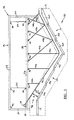
- Figure 1 is a side elevation view of one preferred embodiment of an unstacking conveyor
- Figure 2 is a simplified perspective view of the unstacking conveyor of Figure 1 ;
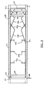
- Figure 3 is a top plan view of the unstacking conveyor of Figure 1 ;
- Figure 4 is an exploded partial elevation view of the unstacking conveyor of Figure 1 in operation.
- the unstacking conveyor 10 includes a conveyor 11 comprising a feed conveyor 12, and two angled conveyors 14 and 16; specifically a declined conveyor 14 and an inclined conveyor 16.
- Each of the angled conveyors 14 and 16 is made up of a plurality of individual angled conveyors 14a, 14b, 14c, and 16a, 16b, and 16c, respectively.
- Each of the conveyors 12, 14 and 16, include a moving conveying surface illustrated herein as a belt.
- the angled conveyors 14, 16 may also include at least one individual conveyor that is substantially horizontal. Additional details regarding the configuration and operation of such angled conveyors 14 and 16 is provided in previously incorporated U.S. Patent No. 6,491,154 to Ydoate, et al .
- the conveyor 11 simply comprises a single angled conveyor.
- the single angled conveyor is preferably an inclined conveyor 16.
- a support structure 18 is coupled to the conveyor 11.
- a support structure can be coupled to the building floor or other building structure.
- the support structure 18 includes a fixed support frame 19 comprising four upright corner posts 20.
- the posts 20 are coupled at their lower ends to the conveyor 11.
- the posts 20 are coupled to each other at their upper ends by a pair of longitudinal support rails 22 and a pair of transverse support rails 24.
- the fixed support frame 19 includes the posts 20, the longitudinal support rails 22 and the transverse support rails 24.
- the support structure 18 additionally includes a vertically movable support frame 25.
- the vertically movable support frame 25 includes a pair of longitudinal support rails 26 and a pair of transverse support rails 28 coupled together.
- One of the transverse support rails 28 is indirectly coupled to the pair of longitudinal support rails 26 via a bracket 30 that locates the transverse support rail 28 vertically above the longitudinal support rails 26.
- Such a configuration can be desirable to increase the initial contact angle as discussed hereinafter.
- the vertically movable support frame 25 is movably coupled to the fixed support frame 19.
- a bracket 32 (seen in Figure 2 ) is coupled to each end of the longitudinal support rails 26 to extend from the interior face at the ends of the longitudinal support rails 26.
- the movable support frame 25 is horizontally fixed in position in relation to the posts 20 of the fixed support frame 19, but can move vertically with the bracket 32 riding along the interior faces of the posts 20.
- Frame support lines 34 couple the movable support frame 25 to the fixed support frame 19 via brackets 40.
- the frame support lines 34 extend around pulleys 36 and through interior cavities of the posts 20 and rails 22 and 24 to a vertical adjustment mechanism 38.
- the vertical adjustment mechanism 38 includes a hand crank.
- the vertical adjustment mechanism can comprise an electronically controlled or manually actuated switch and motorized system.
- Surface support lines 44 couple the movable support frame 25 to a stationary surface 42 via brackets 46.
- lines includes wires, cables, string, twine, ropes and equivalent structures.
- stationary means that the surface does not move forward to impart any forward conveying force to any articles being conveyed. Instead, any limited forward movement of the surface results only from contact with articles being conveyed forward by the conveying system. To be clear, in this context stationary does not relate to movement of the surface which may occur in any other direction. Specifically, stationary does not relate to the potential for vertical movement of the surface.
- the surface support lines 44 all extend at an angle toward the middle of the stationary surface.
- the surface support lines 44 are provided in pairs 44a-44f so that a laterally outward force exerted on the stationary surface 42 by one of the surface support lines 44 is counterbalanced by the other surface support line in the pair. As a result, the surface support lines 44 tend to maintain the stationary surface centered above the angled conveyors 14 and 16.
- the surface support lines above the declined conveyor 44a-44c extend substantially vertically as viewed from a side elevation perspective as seen, for example, in Figure 1 .
- the input end of the stationary surface 42 is coupled to the transverse rail 28.
- the surface support lines 44a-44c and the transverse rail 28 tend to maintain the surface 42 in a stationary position above the declined conveyor 14.
- some of the surface support lines 44d-44f above the inclined conveyor 16 extend at an angle that is substantially perpendicular to a the stationary surface 42 in a resting position as viewed from a side elevation perspective. Some others of the surface support lines 44g-44h above the inclined conveyor 16 extend at an acute angle of the stationary surface 42 in a resting position as viewed from a side elevation perspective. As a result, the surface support lines 44 tend to maintain the surface in a stationary position above the inclined conveyor 16. As defined herein, the surface 42 is stationary despite limited forward movement that might occur as a result of the surface 42 being raised as articles pass under it. Such movement would typically be in a direction normal to the conveying surface. The surface support lines 44 suspend the stationary surface 42 above the conveyor 11 so that it does not contact the moving conveying surfaces thereof.
- the stationary surface 42 is positioned above the declined conveyor 14 to provide an input opening 48 between the declined conveyor 14 and the stationary surface 42.
- the stationary surface 42 is the downward facing surface (toward the conveyors 14 and 16) of the supported material.
- the input opening 48 is associated with a declined conveyor 14, but it may alternatively be associated with an inclined conveyor 16 or a feed conveyor 12.
- the height H of the input opening 48 is typically greater than the maximum expected height of the stream of articles being conveyed.
- the height H of the input opening 48 can optionally be adjustable.
- the frame support lines 34 and pulleys 36 are configured to raise and lower the vertically movable frame 25 through operation of the hand crank 38.
- the stationary surface 42 can be raised or lowered.
- vertical adjustment of the movable frame 25 can permit access to articles below the stationary surface 42.
- vertical adjustment of the movable frame 25 can permit selective use by positioning the stationary surface 42 at an appropriate height, or non-use of the stationary surface by raising the stationary surface 42 to a height at which it will not contact the article stream moving along the conveyor 11.
- an initial contact angle I Associated with the input opening 48 is an initial contact angle I between the declined conveyor 14 and the stationary surface 42.
- the articles initially contact the stationary surface 42 the initial contact angle I.
- This initial contact angle I is sufficiently small that any friction between the articles and the stationary surface 42 can be overcome by the friction between the articles and the declined conveyor 14. As a result, the articles continue to be conveyed along the declined conveyor 14 and are not stopped by their initial contact with the stationary surface 42.
- Friction from the contact between the stationary surface 42 and the articles, including the friction of this initial contact, can also be reduced by providing the stationary surface 42 with a low coefficient of friction.
- the coefficient of friction is preferably less than about 0.5; more preferably, less than about 0.4; and even more preferably, less than about 0.3.
- the stationary surface 42 can be provided by a uniform sheet of material, resulting in a coefficient of friction that is the same along the length of the stationary surface.
- Exemplary preferred materials include polycarbonate and low friction conveyor belting.
- the stationary surface is comprised of a uniform sheet of polycarbonate, having a thickness of about 1/8 inch. This material has the additional advantage of being transparent, which allows visual access to the articles through the stationary surface.
- different materials or coatings can be used to provide different coefficients of friction at different points along the length of the stationary surface, or to adjust the weight associated with the stationary surface 42, or both.
- the articles can be generally cube-shaped, i.e., all side dimensions are roughly equivalent.
- Such generally cubed-shaped articles have a tendency to forward-rotate on a declined conveyor 14, thereby rolling down the declined conveyor 14 toward the bottom thereof.
- such generally cube-shaped articles have a tendency to counter-rotate on an inclined conveyor 16, thereby rolling down the inclined conveyor 16 toward the bottom thereof.
- the weight associated with the stationary surface 42 resists the tendency of articles to roll down toward the bottom of the angled conveyor 14 and 16.
- the stationary surface 42 resists any tendency to roll down the angled conveyor 14 and 16.
- the declined conveyor 14 instead of forward-rotating as occurs with rolling down the angle conveyor, generally round articles will counter-rotate.
- the stationary conveyor 16 instead of tending to move down the angled conveyor 16 as occurs with rolling down the inclined conveyor 16, such generally round-shaped articles move up the inclined conveyor 16.
- Both the counter-rotation and moving up the inclined surface described above occur as a result of the generally round-shaped articles rolling on the stationary surface 42.
- the stationary surface 42 preferably generates sufficient friction to cause such generally round-shaped articles to roll on the stationary surface 42.
- a counter-directional resistance force F2 is a function of the friction coefficient, the stiffness contact angle S, and the force F1 resulting from the weight of the stationary surface acting on the article.
- the moment generated by F2 preferably does not exceed the upward force typically generated as a result of the F2 moment exceeding the total downward weight force F1. In other words, it may be beneficial for the cubic type items to slide along the stationary surface.
- the stiffness contact angle is preferably less than about 20 degrees; more preferably, less than about 15 degrees; and even more preferably, less than about 10 degrees.
- the thickness of the sheet is preferably from about 1/16 inches to about 3/16 inches; and more preferably, from about 3/32 inches to about 5/32 inches, or 1/8 inches. It should be understood, however, that the ideal thickness may vary with the size and weight of an article. For example, smaller articles may require thinner materials and larger articles may require thicker materials, assuming a similar flexural modulus.
- F1 and F2 are coordinated such that enough downward force is provided to resist or oppose such a downward rotation tendency.
- the conveyor system may include only an inclined conveyor.
- a declined conveyor would not be provided.
- the vertically movable support frame is eliminated in such an alternative preferred embodiment.
- the surface support lines would be attached directly to appropriately positioned longitudinal rails of a fixed support frame.
Abstract
Description
- The present disclosure relates to belt conveyors for conveying articles, and more particularly, to such conveyors for unstacking the articles.
- The statements in this section merely provide background information related to the present disclosure and may not constitute prior art.
- The handling of items such as cartons, parcels, bundles, magazines, polybags, etc. often involves conveying the items in a bulk stream while stacked one upon the other. In order for the items to be properly handled, e.g., to redirect magazines to their intended destination, it may be necessary to first unstack the items. A belt conveyor can be arranged at a relatively steep angle to help unstack articles as they are being conveyed. The relatively steep angle can be at a downward angle (i.e., declined) or at an upward angle (i.e., inclined). In some instances, both a declined conveyor section and an inclined conveyor section can be used together in sequence.
- As the articles are conveyed along the angled conveyor, upper articles that are stacked on lower articles tend to slide off. In addition, the angled conveyor can be made up of multiple conveyor belt segments, where each subsequent downstream belt can move at an increased belt travel speed to provide belt space for the upper articles as they slide off the lower articles.
U.S. Patent No, 6,491,154 to Ydoate, et al . discloses one exemplary unstacking belt conveyor, the disclosure of which is hereby incorporated herein by reference in its entirety. - The present disclosure relates to a conveyor for unstacking articles in an article stream. This includes an angled conveyor and a stationary surface suspended above the angled conveyor to contact the article stream. The stationary surface may be positioned to exert a downward force on the articles. The stationary surface resists the tendency of articles to roll down toward the bottom of the angled conveyor.
- In other aspects, the disclosure provides an inclined conveyor and a stationary surface suspended above the inclined conveyor to contact the article stream. The stationary surface exerts a moment on one of the articles related to an effective weight of the stationary surface acting on the one of the articles. The moment is greater than a counter-moment exerted on the one of the articles related to a coefficient of friction of the stationary surface.
- In yet another aspect, a conveyor system for unstacking articles in a article stream is provided including a feed conveyor, a declined conveyor, and an inclined conveyor. A declined stationary surface is provided and suspended above the declined conveyor and positioned to exert a counter-moment on the articles related to the weight of the declined stationary surface and the coefficient of sliding friction of the declined stationary support surface. The counter-moment is sufficient to resist forward rotation of the articles down the declined conveyor. An inclined stationary surface is provided suspended above the inclined conveyor and positioned to exert a forward-moment on the articles related to the weight of the inclined stationary surface and the coefficient of sliding friction of the inclined stationary surface. The forward-moment is sufficient to resist counter-rotation of the articles that results in movement of the articles down the inclined conveyor.
- The present disclosure also provides a method of unstacking articles in an article stream. The method may comprise suspending a stationary surface above an inclined conveyor. Articles may be fed along a conveyor to the inclined conveyor. The method includes exerting a forward conveying force on one of the articles due to friction between each article and the angled conveyor surface. A moment may be exerted on the one of the articles related to an effective weight of the stationary surface acting on the one of the articles that is greater than a counter-moment related to a coefficient of friction of the stationary surface acting on the one of the articles.
- In another method of unstacking articles in an article stream, the present disclosure provides positioning a declined stationary surface above a declined conveyor and feeding the articles to the declined conveyor. The articles may be sandwiched between the declined conveyor and the stationary surface during a declined sandwiching period. The method includes conveying the articles forward due to the declined conveyor during the declined sandwiching period and exerting a counter-moment on the articles related to the weight of the stationary support surface and the coefficient of friction of the stationary support surface. The counter-movement is sufficient to resist forward rotation of the articles down the declined conveyor during the declined sandwiching period. An inclined stationary surface may be positioned above an inclined conveyor and articles are fed to the inclined conveyor. The articles may be sandwiched between the inclined conveyor and the stationary surface during an inclined sandwiching period. The method further includes conveying the secondarily sandwiched articles forward due to the inclined conveyor during the inclined sandwiching period and exerting a forward-moment on the articles related to the weight of the inclined stationary surface and the coefficient of friction of the inclined stationary surface. The forward-movement is sufficient to resist counter-rotation of the articles that results in movement of the articles down the inclined conveyor during the inclined sandwiching period.
- Further areas of applicability will become apparent from the description provided herein. It should be understood that the description and specific examples are intended for purposes of illustration only and are not intended to limit the scope of the present disclosure.
- The drawings described herein are for illustration purposes only and are not intended to limit the scope of the present disclosure in any way.
-
Figure 1 is a side elevation view of one preferred embodiment of an unstacking conveyor; -
Figure 2 is a simplified perspective view of the unstacking conveyor ofFigure 1 ; -
Figure 3 is a top plan view of the unstacking conveyor ofFigure 1 ; and -
Figure 4 is an exploded partial elevation view of the unstacking conveyor ofFigure 1 in operation. - The following description is merely exemplary in nature and is not intended to limit the present disclosure, application, or uses. It should be understood that throughout the drawings, corresponding reference numerals indicate like or corresponding parts and features.
- Referring to
Figures 1-3 , one preferred embodiment of anunstacking conveyor 10 is illustrated. As illustrated, theunstacking conveyor 10 includes a conveyor 11 comprising afeed conveyor 12, and twoangled conveyors 14 and 16; specifically a declinedconveyor 14 and an inclined conveyor 16. Each of theangled conveyors 14 and 16 is made up of a plurality of individualangled conveyors 14a, 14b, 14c, and 16a, 16b, and 16c, respectively. Each of theconveyors angled conveyors 14, 16 may also include at least one individual conveyor that is substantially horizontal. Additional details regarding the configuration and operation of suchangled conveyors 14 and 16 is provided in previously incorporatedU.S. Patent No. 6,491,154 to Ydoate, et al . In an alternative, the conveyor 11 simply comprises a single angled conveyor. For example, the single angled conveyor is preferably an inclined conveyor 16. - A
support structure 18 is coupled to the conveyor 11. In an alternative, a support structure can be coupled to the building floor or other building structure. Thesupport structure 18 includes afixed support frame 19 comprising fourupright corner posts 20. Theposts 20 are coupled at their lower ends to the conveyor 11. Theposts 20 are coupled to each other at their upper ends by a pair oflongitudinal support rails 22 and a pair oftransverse support rails 24. Thus, thefixed support frame 19 includes theposts 20, thelongitudinal support rails 22 and thetransverse support rails 24. - In the illustrated embodiment, the
support structure 18 additionally includes a verticallymovable support frame 25. The verticallymovable support frame 25 includes a pair oflongitudinal support rails 26 and a pair oftransverse support rails 28 coupled together. One of the transverse support rails 28 is indirectly coupled to the pair of longitudinal support rails 26 via abracket 30 that locates thetransverse support rail 28 vertically above the longitudinal support rails 26. Such a configuration can be desirable to increase the initial contact angle as discussed hereinafter. - The vertically
movable support frame 25 is movably coupled to the fixedsupport frame 19. A bracket 32 (seen inFigure 2 ) is coupled to each end of the longitudinal support rails 26 to extend from the interior face at the ends of the longitudinal support rails 26. As a result, themovable support frame 25 is horizontally fixed in position in relation to theposts 20 of the fixedsupport frame 19, but can move vertically with thebracket 32 riding along the interior faces of theposts 20. Frame support lines 34 couple themovable support frame 25 to the fixedsupport frame 19 viabrackets 40. Theframe support lines 34 extend around pulleys 36 and through interior cavities of theposts 20 and rails 22 and 24 to avertical adjustment mechanism 38. In the illustrated preferred embodiment, thevertical adjustment mechanism 38 includes a hand crank. Alternatively, the vertical adjustment mechanism can comprise an electronically controlled or manually actuated switch and motorized system. - Surface support lines 44 couple the
movable support frame 25 to astationary surface 42 viabrackets 46. As used herein, "lines" includes wires, cables, string, twine, ropes and equivalent structures. As used herein in regard to thesurface 42, "stationary" means that the surface does not move forward to impart any forward conveying force to any articles being conveyed. Instead, any limited forward movement of the surface results only from contact with articles being conveyed forward by the conveying system. To be clear, in this context stationary does not relate to movement of the surface which may occur in any other direction. Specifically, stationary does not relate to the potential for vertical movement of the surface. - As seen in
Figures 2 and3 , thesurface support lines 44 all extend at an angle toward the middle of the stationary surface. In addition, thesurface support lines 44 are provided in pairs 44a-44f so that a laterally outward force exerted on thestationary surface 42 by one of the surface support lines 44 is counterbalanced by the other surface support line in the pair. As a result, thesurface support lines 44 tend to maintain the stationary surface centered above theangled conveyors 14 and 16. - The surface support lines above the declined conveyor 44a-44c extend substantially vertically as viewed from a side elevation perspective as seen, for example, in
Figure 1 . The input end of thestationary surface 42 is coupled to thetransverse rail 28. As a result, the surface support lines 44a-44c and thetransverse rail 28 tend to maintain thesurface 42 in a stationary position above the declinedconveyor 14. - In addition, some of the
surface support lines 44d-44f above the inclined conveyor 16 extend at an angle that is substantially perpendicular to a thestationary surface 42 in a resting position as viewed from a side elevation perspective. Some others of thesurface support lines 44g-44h above the inclined conveyor 16 extend at an acute angle of thestationary surface 42 in a resting position as viewed from a side elevation perspective. As a result, thesurface support lines 44 tend to maintain the surface in a stationary position above the inclined conveyor 16. As defined herein, thesurface 42 is stationary despite limited forward movement that might occur as a result of thesurface 42 being raised as articles pass under it. Such movement would typically be in a direction normal to the conveying surface. Thesurface support lines 44 suspend thestationary surface 42 above the conveyor 11 so that it does not contact the moving conveying surfaces thereof. - Returning to
Figure 1 , thestationary surface 42 is positioned above the declinedconveyor 14 to provide an input opening 48 between the declinedconveyor 14 and thestationary surface 42. For clarity, thestationary surface 42 is the downward facing surface (toward theconveyors 14 and 16) of the supported material. In the illustrated embodiment, the input opening 48 is associated with a declinedconveyor 14, but it may alternatively be associated with an inclined conveyor 16 or afeed conveyor 12. The height H of the input opening 48 is typically greater than the maximum expected height of the stream of articles being conveyed. The height H of the input opening 48 can optionally be adjustable. - As illustrated, the
frame support lines 34 andpulleys 36 are configured to raise and lower the verticallymovable frame 25 through operation of the hand crank 38. Thus, thestationary surface 42 can be raised or lowered. In addition to optionally permitting adjustment of the input opening height H, vertical adjustment of themovable frame 25 can permit access to articles below thestationary surface 42. Further, vertical adjustment of themovable frame 25 can permit selective use by positioning thestationary surface 42 at an appropriate height, or non-use of the stationary surface by raising thestationary surface 42 to a height at which it will not contact the article stream moving along the conveyor 11. - Associated with the input opening 48 is an initial contact angle I between the declined
conveyor 14 and thestationary surface 42. As the plurality of articles in the stream of articles is delivered to the declinedconveyor 14 by the feed conveyor and travel along the declinedconveyor 14, the articles initially contact thestationary surface 42 the initial contact angle I. This initial contact angle I is sufficiently small that any friction between the articles and thestationary surface 42 can be overcome by the friction between the articles and the declinedconveyor 14. As a result, the articles continue to be conveyed along the declinedconveyor 14 and are not stopped by their initial contact with thestationary surface 42. - Friction from the contact between the
stationary surface 42 and the articles, including the friction of this initial contact, can also be reduced by providing thestationary surface 42 with a low coefficient of friction. For example, the coefficient of friction is preferably less than about 0.5; more preferably, less than about 0.4; and even more preferably, less than about 0.3. Thestationary surface 42 can be provided by a uniform sheet of material, resulting in a coefficient of friction that is the same along the length of the stationary surface. Exemplary preferred materials include polycarbonate and low friction conveyor belting. In a particularly preferred embodiment, the stationary surface is comprised of a uniform sheet of polycarbonate, having a thickness of about 1/8 inch. This material has the additional advantage of being transparent, which allows visual access to the articles through the stationary surface. Alternatively, different materials or coatings can be used to provide different coefficients of friction at different points along the length of the stationary surface, or to adjust the weight associated with thestationary surface 42, or both. - The articles can be generally cube-shaped, i.e., all side dimensions are roughly equivalent. Such generally cubed-shaped articles have a tendency to forward-rotate on a declined
conveyor 14, thereby rolling down the declinedconveyor 14 toward the bottom thereof. In addition, such generally cube-shaped articles have a tendency to counter-rotate on an inclined conveyor 16, thereby rolling down the inclined conveyor 16 toward the bottom thereof. The weight associated with thestationary surface 42, however, resists the tendency of articles to roll down toward the bottom of theangled conveyor 14 and 16. - When the articles are generally round-shaped, the
stationary surface 42 resists any tendency to roll down theangled conveyor 14 and 16. On the declinedconveyor 14, instead of forward-rotating as occurs with rolling down the angle conveyor, generally round articles will counter-rotate. Thus, instead of rolling down the declinedconveyor 14, such generally round-shaped articles will roll down thesupport surface 42. On the inclined conveyor 16, instead of tending to move down the angled conveyor 16 as occurs with rolling down the inclined conveyor 16, such generally round-shaped articles move up the inclined conveyor 16. Both the counter-rotation and moving up the inclined surface described above occur as a result of the generally round-shaped articles rolling on thestationary surface 42. Thus, thestationary surface 42 preferably generates sufficient friction to cause such generally round-shaped articles to roll on thestationary surface 42. - Referring to
Figure 4 and returning to generally cube-shaped articles, the stiffness of the stationary surface can impact the relevant forces. A counter-directional resistance force F2 is a function of the friction coefficient, the stiffness contact angle S, and the force F1 resulting from the weight of the stationary surface acting on the article. On an inclined conveyor as seen inFigure 4 , the moment generated by F2 preferably does not exceed the upward force typically generated as a result of the F2 moment exceeding the total downward weight force F1. In other words, it may be beneficial for the cubic type items to slide along the stationary surface. The stiffness contact angle is preferably less than about 20 degrees; more preferably, less than about 15 degrees; and even more preferably, less than about 10 degrees. In addition, when the stationary surface is comprised of a uniform sheet of polycarbonate, the thickness of the sheet is preferably from about 1/16 inches to about 3/16 inches; and more preferably, from about 3/32 inches to about 5/32 inches, or 1/8 inches. It should be understood, however, that the ideal thickness may vary with the size and weight of an article. For example, smaller articles may require thinner materials and larger articles may require thicker materials, assuming a similar flexural modulus. - In instances where the stationary surface is above the declined conveyor, there may be a tendency of articles to counter rotate. Thus, in certain aspects, F1 and F2 are coordinated such that enough downward force is provided to resist or oppose such a downward rotation tendency.
- In an alternative preferred embodiment not specifically illustrated herein, the conveyor system may include only an inclined conveyor. Thus, a declined conveyor would not be provided. In addition, the vertically movable support frame is eliminated in such an alternative preferred embodiment. For example, the surface support lines would be attached directly to appropriately positioned longitudinal rails of a fixed support frame. Although these two alternatives are described herein in relation to a single alternative embodiment, as with all of the alternatives described herein, the various alternatives may be individually selected to provide any desired combination of alternatives for an alternative preferred embodiment.
- The foregoing discussion discloses and describes merely exemplary preferred arrangements of the present invention. One skilled in the art will readily recognize from such discussion, and from the accompanying drawings and claims, that various changes, modifications and variations can be made therein without departing from the spirit and scope of the invention as defined in the following claims. Further, there may be alternative preferred arrangements to those specifically described herein, and therefore, the use of "preferred" herein or the failure to mention a specific alternative is not intended to exclude any such alternative arrangements.
Claims (12)
- A conveyor for unstacking articles in an article stream comprising:an angled conveyor;a stationary surface suspended above the angled conveyor to contact the article stream;wherein the stationary surface is positioned to exert a downward force on the articles; and wherein the stationary surface resists the tendency of articles to roll down toward the bottom of the angled conveyor.
- The conveyor according to Claim 1, wherein the stationary surface has a coefficient of friction below a threshold that would induce counter-rotation in at least one of the articles that has a generally cube-shape, and wherein the stationary surface has a weight, stiffness, and coefficient of friction that is above a threshold required to cause counter-movement relative to the stationary surface of at least another one of the articles that has a generally circular shape.
- The conveyor according to claim 1 or 2, wherein an initial contact angle is formed between the stationary surface and the angled conveyor, and
wherein the initial contact angle is sufficiently small that any friction between the articles and the stationary surface is less than any friction between the articles and the declined conveyor. - The conveyor according to any one of claims 1 to 3 wherein the stationary surface comprises a transparent material, thereby permitting visual access to the articles through the stationary surface.
- The conveyor according to any one of claims 1 to 4, wherein the stationary surface is associated with a material having a stiffness resulting in a stiffness contact angle S below that at which a counter-moment generated by any friction between one of the articles and the stationary surface is less than a moment generated by an effective weight of the stationary surface acting on the one of the articles.
- The conveyor according to any one of claims 1 to 5, further comprising a support frame and a plurality of support lines coupling the support frame to the stationary surface, thereby suspending the stationary surface, above the angle conveyor to contact the article stream and wherein, at least, some of the support lines are angled toward a center of the stationary surface as they approach the stationary surface and wherein at least some of the support lines extend at an angle that is substantially perpendicular to the stationary surface in a resting position as viewed from a side elevation perspective.
- The conveyor according to Claim 1, further comprising a support frame and a plurality of support lines coupling the support frame to the stationary surface, thereby suspending the stationary surface above the angle conveyor to contact the article stream and wherein the support frame comprises a fixed support frame and a vertically movable support frame coupled to the fixed support frame via a plurality of frame support lines, and further comprising a vertical adjustment mechanism associated with the frame support lines.
- A method of unstacking articles in an article stream, the method comprising:suspending a stationary surface above an inclined conveyor;feeding the articles along a conveyor to the inclined conveyor;exerting a forward conveying force on one of the articles due to friction between each article and the angled conveyor surface;exerting a moment on the one of the articles related to an effective weight of the stationary surface acting on the one of the articles that is greater than a counter-moment related to a coefficient of friction of the stationary surface acting on the one of the articles.
- The method according to Claim 8, wherein exerting a forward conveying force on one of the articles and exerting a moment on the one of the articles occur simultaneously as a result of sandwiching the one of the articles between the stationary surface and the inclined conveyor and sliding the one of the articles along the stationary surface.
- The method according to claim 8 or 9, further comprising providing the stationary surface with a sufficiently low coefficient of friction that an associated friction force that is exerted on the one of the articles in a rearward conveying direction that is less than the forward conveying force.
- The method according to any of claim 8 to 10, further comprising raising the stationary support surface to a minimum height above the inclined conveyor that is greater than an expected height of the article stream, thereby temporarily removing any contact between the articles and the stationary surface when the articles have a configuration that does not tend to move down the inclined conveyor during operation.
- The method according to any of claims 8 to 11, further comprising adjusting the stationary support surface to create an input opening having a height above the inclined conveyor that is greater than an expected maximum height of the article stream and to form an initial contact angle between the stationary surface and the angled conveyor that is sufficiently small that any friction between the articles and the stationary surface is less than any friction between the articles and the declined conveyor.
Applications Claiming Priority (1)
| Application Number | Priority Date | Filing Date | Title |
|---|---|---|---|
| US11/962,916 US7938252B2 (en) | 2007-12-21 | 2007-12-21 | Unstacking conveyor with floating surface |
Publications (2)
| Publication Number | Publication Date |
|---|---|
| EP2072423A1 true EP2072423A1 (en) | 2009-06-24 |
| EP2072423B1 EP2072423B1 (en) | 2011-06-15 |
Family
ID=40352142
Family Applications (1)
| Application Number | Title | Priority Date | Filing Date |
|---|---|---|---|
| EP08291224A Active EP2072423B1 (en) | 2007-12-21 | 2008-12-19 | Unstacking conveyor with floating surface |
Country Status (4)
| Country | Link |
|---|---|
| US (1) | US7938252B2 (en) |
| EP (1) | EP2072423B1 (en) |
| AT (1) | ATE512915T1 (en) |
| WO (1) | WO2009085906A2 (en) |
Cited By (3)
| Publication number | Priority date | Publication date | Assignee | Title |
|---|---|---|---|---|
| WO2011112449A3 (en) * | 2010-03-08 | 2011-10-27 | Laitram, L.L.C. | Package-culling conveyor system and method |
| US10246267B2 (en) | 2015-05-14 | 2019-04-02 | Laitram, L.L.C. | Inclined-roller destacker |
| EP3971116A1 (en) * | 2020-09-17 | 2022-03-23 | Caljan A/S | Systems, devices, and methods for extendable conveyors |
Families Citing this family (7)
| Publication number | Priority date | Publication date | Assignee | Title |
|---|---|---|---|---|
| US9038810B2 (en) | 2013-03-12 | 2015-05-26 | Fives Intralogistics Corp. | Singulator conveyor |
| CA3066078C (en) * | 2017-06-06 | 2022-03-01 | Material Handling Systems, Inc. | System and method for identifying and transferring parcels from a first conveyor to a second conveyor |
| US10875214B2 (en) * | 2017-09-13 | 2020-12-29 | Broadview Group International, Llc | Friction device for fiber-granule separation |
| US10870543B1 (en) * | 2019-03-29 | 2020-12-22 | Amazon Technologies, Inc. | Item singulation system and method |
| US11014765B1 (en) * | 2019-03-29 | 2021-05-25 | Amazon Technologies, Inc. | System and method for collimating items |
| US11753256B2 (en) | 2020-06-22 | 2023-09-12 | Material Handling Systems, Inc. | Conveyor system with multiple robot singulators |
| CN115479618A (en) * | 2021-05-26 | 2022-12-16 | 泰科电子(上海)有限公司 | Carrier and inspection system |
Citations (5)
| Publication number | Priority date | Publication date | Assignee | Title |
|---|---|---|---|---|
| BE664183A (en) * | 1964-05-21 | 1965-11-19 | ||
| GB2017034A (en) * | 1978-03-18 | 1979-10-03 | Matsuo M | Belt conveyor apparatus |
| US5161678A (en) * | 1991-08-19 | 1992-11-10 | Garvey Corporation | Accumulator cover |
| DE9302962U1 (en) * | 1993-02-25 | 1993-05-13 | A. Hirschenkraemer Transportanlagenbau Hermann Thiessen Gmbh, 2000 Hamburg, De | |
| US6491154B2 (en) | 2000-12-26 | 2002-12-10 | Sandvik Sorting Systems, Inc. | Unstacker for unstacking items conveyed in a bulk stream |
Family Cites Families (71)
| Publication number | Priority date | Publication date | Assignee | Title |
|---|---|---|---|---|
| US1629776A (en) * | 1927-05-24 | cutler | ||
| US997276A (en) * | 1909-06-28 | 1911-07-11 | Grove D Curtis | Conveying-chute. |
| US1017433A (en) * | 1911-08-31 | 1912-02-13 | Paul Russell Lovell | Attachment for hay-loaders. |
| US1498914A (en) * | 1923-04-12 | 1924-06-24 | William G Hoffman | Potato-digger conveyer apron |
| US2167818A (en) * | 1937-03-15 | 1939-08-01 | Charles W Wagner | Conveyer |
| US2164128A (en) * | 1938-04-11 | 1939-06-27 | Earl B Spencer | Means for suspending and moving a platform or the like |
| US2221236A (en) * | 1939-06-30 | 1940-11-12 | Jr Jacob D Gay | Elevator cover |
| US2529620A (en) * | 1948-05-19 | 1950-11-14 | Carl H Marnach | Husking and cleaning machine |
| US2803463A (en) * | 1952-12-02 | 1957-08-20 | American Mach & Foundry | Ball lift |
| US2785810A (en) * | 1955-05-18 | 1957-03-19 | Alphonse P Kneib | Bale loading machine |
| US2844926A (en) * | 1956-04-13 | 1958-07-29 | David W Mattos | Machine for spreading halved fruit on drying trays |
| US3819030A (en) * | 1972-09-18 | 1974-06-25 | W & H Conveyor Syst Inc | Conveyor apparatus |
| US3963117A (en) * | 1973-04-11 | 1976-06-15 | Union Carbide Corporation | Article brake for inclined conveyor |
| US4103767A (en) * | 1977-01-25 | 1978-08-01 | W & H Conveyor Systems, Inc. | Elevating apparatus |
| JPS5818292B2 (en) * | 1980-03-29 | 1983-04-12 | 友末 弘 | A device that arranges chicken eggs in a straight line. |
| US4815582A (en) * | 1981-12-24 | 1989-03-28 | Francesco Canziani | Feeding apparatus particularly for machines for the conveyance and sorting of objects |
| CH659192A5 (en) * | 1982-09-14 | 1987-01-15 | Seranina Ag Patentverwert | DEVICE FOR LIFTING THE BALL IN THE BALL RETURN TRACK OF A TAPERED PLANT. |
| SU1433886A1 (en) * | 1984-10-24 | 1988-10-30 | Всесоюзный Институт По Проектированию Организации Энергетического Строительства "Оргэнергострой" | Belt conveyer transfer unit |
| IT8520779V0 (en) | 1985-02-13 | 1985-02-13 | Canziani Francesco | AUTONOMOUS HANDLING TROLLEY, FOR SORTING SYSTEMS |
| EP0226123A3 (en) * | 1985-12-03 | 1988-08-10 | Matsushita Electric Industrial Co., Ltd. | Method for producing transparent plastic article |
| IT211603Z2 (en) * | 1985-12-20 | 1989-04-07 | Canziani Francesco | TRANSPORT AND UNLOADING UNIT FOR SORTING OBJECTS. |
| IT1198074B (en) | 1986-11-10 | 1988-12-21 | Francesco Canziani | SORTING EQUIPMENT WITH TRANSPORTATION DEVICES FOR OBJECTS TO BE SORTED PREPOSITIONABLE ACCORDING TO THE DISCHARGE DESTINATION |
| IT1217694B (en) | 1988-05-23 | 1990-03-30 | Francesco Canziani | METHOD FOR THE CONTROL OF THE EXACT POSITIONING OF THE OBJECTS TO BE SORTED IN AN AUTOMATIC SORTING SYSTEM |
| US4938335A (en) | 1988-05-23 | 1990-07-03 | Francesco Canziani | Method and devices for controlling the unloading of the items in an automatic sorting plant |
| GB2224147B (en) | 1988-10-21 | 1992-08-05 | Francesco Canziani | Process and apparatus for sorting items |
| IT1235066B (en) | 1988-11-14 | 1992-06-17 | Francesco Canziani | Stacking apparatus |
| EP0409246B1 (en) * | 1989-07-20 | 1997-04-23 | SANYO ELECTRIC Co., Ltd. | Liquid crystal projector |
| IT1248842B (en) | 1990-06-13 | 1995-01-30 | Francesco Canziani | PLANT FOR THE SORTING AND DISTRIBUTION OF OBJECTS SUCH AS PACKAGES OR SIMILAR |
| IT1243453B (en) | 1990-10-17 | 1994-06-10 | Francesco Canziani | SORTING EQUIPMENT AND METHOD FOR CHECKING ITSELF. |
| US5113993A (en) | 1991-04-01 | 1992-05-19 | Sandvik Process Systems, Inc. | Three way splitter |
| US5072663A (en) * | 1991-04-26 | 1991-12-17 | Seafood Equipment Development Corporation | Shrimp cooking apparatus |
| US5161679A (en) * | 1991-06-28 | 1992-11-10 | Guardian Electric Manufacturing Company | Electrical trigger switch with safety features |
| US5222586A (en) | 1992-04-09 | 1993-06-29 | Sandvik Process Systems, Inc. | Methods and apparatus for conveying packages in a manner minimizing jams |
| JPH06135525A (en) | 1992-10-27 | 1994-05-17 | Iseki Tory Tech Inc | Conveyer device |
| US5275272A (en) | 1993-04-06 | 1994-01-04 | Sandvik Process Systems, Inc. | Conveyor system with article diverting mechanism |
| DK0727371T3 (en) | 1995-02-14 | 2001-10-15 | Santrade Ltd | Conveyor for diverting an object which is transported next to another object |
| IT1275470B (en) | 1995-07-04 | 1997-08-07 | Francesco Canziani | DEVICE TO CONTROL THE MOVEMENT OF THE LOADING / UNLOADING BELT OF A TRANSPORT TROLLEY IN PARTICULAR FOR SORTING EQUIPMENT |
| IT237182Y1 (en) | 1995-09-29 | 2000-09-05 | Francesco Canziani | UNPACKER FOR SMALL FLAT OBJECTS SUCH AS AUDIO / VIDEO CASSETTES OR SIMILAR |
| US5682977A (en) * | 1995-10-05 | 1997-11-04 | Nabisco, Inc. | Vertically adjustable cover for an elongated device and adjustment apparatus therefor |
| IT1276145B1 (en) | 1995-11-16 | 1997-10-27 | Cml Handling Technology S P A | SORTING EQUIPMENT WITH OBJECT TRANSPORT CELLS ON OVERLAYING SHELVES |
| IT237285Y1 (en) | 1995-11-16 | 2000-09-05 | Cml Handling Technology S P A | DISCHARGE HOPPER FOR SORTING EQUIPMENT |
| IT1276144B1 (en) | 1995-11-16 | 1997-10-27 | Cml Handling Technology S P A | APPARATUS AND METHOD FOR LOADING OBJECTS ON A SORTING MACHINE WITH TRANSPORT PLANS ON TWO LEVELS |
| IT237284Y1 (en) | 1995-11-16 | 2000-09-05 | Cml Handling Technology S P A | TROLLEY FOR SORTING PLANTS, WITH TRANSPORT PLAN POSITIONABLE ON MORE LEVELS |
| US5738202A (en) * | 1995-12-21 | 1998-04-14 | Sandvik Sorting Systems, Inc. | Methods and apparatus for establishing a desired positional relationship between random-length articles conveyed in single file |
| US5769204A (en) | 1995-12-21 | 1998-06-23 | Sandvik Sorting Systems, Inc. | Singulator conveyor system having package-return conveyors |
| JPH09316643A (en) | 1996-02-15 | 1997-12-09 | Mitsubishi Materials Corp | Sticking preventing parts for physical vapor deposition system |
| US5950800A (en) * | 1997-07-17 | 1999-09-14 | Sandvik Sorting Systems, Inc. | Conveying methods and apparatus |
| US5934438A (en) * | 1997-07-18 | 1999-08-10 | Sandvik Sorting Systems, Inc. | Gravity conveyor having velocity and back pressure control |
| US6076683A (en) * | 1997-10-29 | 2000-06-20 | Sandvik Sorting Systems, Inc. | Sorter mechanism |
| IT1297026B1 (en) | 1997-12-29 | 1999-08-03 | Cml Handling Technology S P A | HIGH PRODUCTIVITY METHOD AND EQUIPMENT FOR PARCEL SORTING |
| US5918724A (en) * | 1997-12-30 | 1999-07-06 | Sandvik Sorting Systems, Inc. | Low inertia article-diverter blade |
| IT1301695B1 (en) | 1998-06-12 | 2000-07-07 | Cml Handling Technology S P A | BELT FOR A SORTING MACHINE CELL, EQUIPPED WITH RIGHT CORD. |
| IT1301697B1 (en) | 1998-06-12 | 2000-07-07 | Cml Handling Technology S P A | EQUIPMENT FOR THE CLEANING OF THE ROTATING MATS IN MACHINES AND SORTING MACHINES EQUIPPED WITH THE SAID APPARATUS. |
| IT1301696B1 (en) | 1998-06-12 | 2000-07-07 | Cml Handling Technology S P A | METHOD AND EQUIPMENT FOR THE AUTOMATIC LOADING OF MULTIPLE ITEMS ORDERED, ON THE SAME UNIT OF A SORTING MACHINE |
| US5964338A (en) * | 1998-12-16 | 1999-10-12 | Sandvik Sorting Systems, Inc. | Conveyor apparatus having adjustable rollers |
| US6131723A (en) * | 1999-01-21 | 2000-10-17 | Sandvik Sorting Systems, Inc. | Methods and apparatus for conveying packages in manner minimizing jams |
| US6557696B1 (en) * | 2000-06-15 | 2003-05-06 | Mark R. Frich | Inclined conveyor |
| IT1319594B1 (en) | 2000-12-20 | 2003-10-20 | Cml Handling Technology S P A | EQUIPMENT AND METHOD FOR THE ACTIVATION AND CONTROL OF THE SORTING UNIT IN A SORTING MACHINE |
| US20020084174A1 (en) * | 2000-12-29 | 2002-07-04 | Maurice Minardi | Soft drop preform conveyor system |
| JP2002284323A (en) | 2001-03-21 | 2002-10-03 | Honda Motor Co Ltd | Carrying device |
| JP2002284344A (en) | 2001-03-27 | 2002-10-03 | Sandvik Sorting System Kk | Article transfer device |
| ITMI20020785A1 (en) | 2002-04-12 | 2003-10-13 | Sandvik Sorting Systems S P A | DEVICE AND METHOD FOR TRANSFERRING A CROSS BELT SORTING MACHINE ON THE TRAIN OF TROLLEYS THE ELECTRICAL ENERGY REQUIRED BY THE |
| ITMI20020786A1 (en) | 2002-04-12 | 2003-10-13 | Sandvik Sorting Systems S P A | DEVICE TO TRANSFER MECHANICAL ENERGY ON BOARD OF A TRAIN OF TROLLEYS OF A SORTING MACHINE |
| ITMI20020787A1 (en) | 2002-04-12 | 2003-10-13 | Sandvik Sorting Systems S P A | IMPROVED TOWING SYSTEM FOR SORTING MACHINES |
| JP4159309B2 (en) | 2002-05-13 | 2008-10-01 | シネティックソーティング株式会社 | Sorting device having divertor and diverter drive control method |
| US6843367B1 (en) * | 2004-02-03 | 2005-01-18 | Dillin Engineered Systems Corp. | Adjustable top guide assembly for air driven conveyor |
| US6910568B1 (en) * | 2004-02-04 | 2005-06-28 | Sandvik Ab | Methods and apparatus for diverting articles from a conveyor |
| ITBO20040494A1 (en) | 2004-08-03 | 2004-11-03 | Gd Spa | PRODUCT CONVEYANCE UNIT |
| JP4276161B2 (en) | 2004-10-29 | 2009-06-10 | シネティックソーティング株式会社 | Sorting system |
| JP4365310B2 (en) | 2004-12-22 | 2009-11-18 | シネティックソーティング株式会社 | Sorting baggage merge system |
| JP2006200859A (en) | 2005-01-24 | 2006-08-03 | Matsushita Electric Ind Co Ltd | Controller for air conditioner |
-
2007
- 2007-12-21 US US11/962,916 patent/US7938252B2/en active Active
-
2008
- 2008-12-18 WO PCT/US2008/087352 patent/WO2009085906A2/en active Application Filing
- 2008-12-19 EP EP08291224A patent/EP2072423B1/en active Active
- 2008-12-19 AT AT08291224T patent/ATE512915T1/en not_active IP Right Cessation
Patent Citations (5)
| Publication number | Priority date | Publication date | Assignee | Title |
|---|---|---|---|---|
| BE664183A (en) * | 1964-05-21 | 1965-11-19 | ||
| GB2017034A (en) * | 1978-03-18 | 1979-10-03 | Matsuo M | Belt conveyor apparatus |
| US5161678A (en) * | 1991-08-19 | 1992-11-10 | Garvey Corporation | Accumulator cover |
| DE9302962U1 (en) * | 1993-02-25 | 1993-05-13 | A. Hirschenkraemer Transportanlagenbau Hermann Thiessen Gmbh, 2000 Hamburg, De | |
| US6491154B2 (en) | 2000-12-26 | 2002-12-10 | Sandvik Sorting Systems, Inc. | Unstacker for unstacking items conveyed in a bulk stream |
Cited By (6)
| Publication number | Priority date | Publication date | Assignee | Title |
|---|---|---|---|---|
| WO2011112449A3 (en) * | 2010-03-08 | 2011-10-27 | Laitram, L.L.C. | Package-culling conveyor system and method |
| US8528742B2 (en) | 2010-03-08 | 2013-09-10 | Laitram, L.L.C. | Package-culling conveyor system and method |
| US9199281B2 (en) | 2010-03-08 | 2015-12-01 | Laitram, L. L. C. | Conveyor systems and methods |
| US10246267B2 (en) | 2015-05-14 | 2019-04-02 | Laitram, L.L.C. | Inclined-roller destacker |
| EP3971116A1 (en) * | 2020-09-17 | 2022-03-23 | Caljan A/S | Systems, devices, and methods for extendable conveyors |
| US11795008B2 (en) | 2020-09-17 | 2023-10-24 | Caljan A/S | Systems, devices, and methods for extendable conveyors |
Also Published As
| Publication number | Publication date |
|---|---|
| ATE512915T1 (en) | 2011-07-15 |
| EP2072423B1 (en) | 2011-06-15 |
| US7938252B2 (en) | 2011-05-10 |
| US20090159404A1 (en) | 2009-06-25 |
| WO2009085906A2 (en) | 2009-07-09 |
| WO2009085906A3 (en) | 2009-10-01 |
Similar Documents
| Publication | Publication Date | Title |
|---|---|---|
| EP2072423B1 (en) | Unstacking conveyor with floating surface | |
| EP3003928B1 (en) | Conveyor merge assembly | |
| US8464859B2 (en) | Conveyor apparatus for unloading packages from shipping containers | |
| CA2792086C (en) | Package-culling conveyor system and method | |
| FR2886205B1 (en) | RAILING ELEMENT FOR CONVEYING OBJECTS IN SUSPENDED POSITION AND FEEDING DEVICE COMPRISING SUCH A MEMBER | |
| CN205441723U (en) | Mechanical transmission belting | |
| MX2008009634A (en) | Systems and methods for diverting objects. | |
| US5029697A (en) | Clean room conveyor | |
| JP2008531440A (en) | Conveyor equipment for containers such as preforms | |
| JPS6410411B2 (en) | ||
| CA2718881C (en) | Conveyor apparatus for unloading packages from shipping containers | |
| US10118765B2 (en) | Flexible-belt conveyor and methods of conveying | |
| EP2460410B1 (en) | Device and method for lapping dough | |
| JP3443565B2 (en) | Transportation equipment | |
| CA2486054A1 (en) | Multiple insert delivery systems and methods | |
| US7870950B2 (en) | V-shaped product conveyor | |
| KR100727108B1 (en) | Surface cleaning apparatus of belt conveyer | |
| EP1007452B1 (en) | Conveyor apparatus | |
| JP4720631B2 (en) | Sorting equipment | |
| US20170043956A1 (en) | Sheet stacking apparatus having adjustable length conveyor section | |
| EP0652168A1 (en) | Return pipe conveyer | |
| US20210114820A1 (en) | Alignment device for a conveyor | |
| US20090001653A1 (en) | Stacking apparatus having tiltable main conveyor and variable length transfer conveyor | |
| US20080135464A1 (en) | Separating system for separating articles | |
| CN208721211U (en) | Check weighing scale with material issuance device |
Legal Events
| Date | Code | Title | Description |
|---|---|---|---|
| PUAI | Public reference made under article 153(3) epc to a published international application that has entered the european phase |
Free format text: ORIGINAL CODE: 0009012 |
|
| AK | Designated contracting states |
Kind code of ref document: A1 Designated state(s): AT BE BG CH CY CZ DE DK EE ES FI FR GB GR HR HU IE IS IT LI LT LU LV MC MT NL NO PL PT RO SE SI SK TR |
|
| AX | Request for extension of the european patent |
Extension state: AL BA MK RS |
|
| 17P | Request for examination filed |
Effective date: 20091221 |
|
| AKX | Designation fees paid |
Designated state(s): AT BE BG CH CY CZ DE DK EE ES FI FR GB GR HR HU IE IS IT LI LT LU LV MC MT NL NO PL PT RO SE SI SK TR |
|
| 17Q | First examination report despatched |
Effective date: 20100304 |
|
| GRAP | Despatch of communication of intention to grant a patent |
Free format text: ORIGINAL CODE: EPIDOSNIGR1 |
|
| GRAS | Grant fee paid |
Free format text: ORIGINAL CODE: EPIDOSNIGR3 |
|
| GRAA | (expected) grant |
Free format text: ORIGINAL CODE: 0009210 |
|
| AK | Designated contracting states |
Kind code of ref document: B1 Designated state(s): AT BE BG CH CY CZ DE DK EE ES FI FR GB GR HR HU IE IS IT LI LT LU LV MC MT NL NO PL PT RO SE SI SK TR |
|
| REG | Reference to a national code |
Ref country code: GB Ref legal event code: FG4D Ref country code: CH Ref legal event code: EP |
|
| REG | Reference to a national code |
Ref country code: IE Ref legal event code: FG4D |
|
| REG | Reference to a national code |
Ref country code: DE Ref legal event code: R096 Ref document number: 602008007602 Country of ref document: DE Effective date: 20110804 |
|
| REG | Reference to a national code |
Ref country code: NL Ref legal event code: VDEP Effective date: 20110615 |
|
| PG25 | Lapsed in a contracting state [announced via postgrant information from national office to epo] |
Ref country code: LT Free format text: LAPSE BECAUSE OF FAILURE TO SUBMIT A TRANSLATION OF THE DESCRIPTION OR TO PAY THE FEE WITHIN THE PRESCRIBED TIME-LIMIT Effective date: 20110615 Ref country code: HR Free format text: LAPSE BECAUSE OF FAILURE TO SUBMIT A TRANSLATION OF THE DESCRIPTION OR TO PAY THE FEE WITHIN THE PRESCRIBED TIME-LIMIT Effective date: 20110615 Ref country code: NO Free format text: LAPSE BECAUSE OF FAILURE TO SUBMIT A TRANSLATION OF THE DESCRIPTION OR TO PAY THE FEE WITHIN THE PRESCRIBED TIME-LIMIT Effective date: 20110915 Ref country code: SE Free format text: LAPSE BECAUSE OF FAILURE TO SUBMIT A TRANSLATION OF THE DESCRIPTION OR TO PAY THE FEE WITHIN THE PRESCRIBED TIME-LIMIT Effective date: 20110615 |
|
| PG25 | Lapsed in a contracting state [announced via postgrant information from national office to epo] |
Ref country code: AT Free format text: LAPSE BECAUSE OF FAILURE TO SUBMIT A TRANSLATION OF THE DESCRIPTION OR TO PAY THE FEE WITHIN THE PRESCRIBED TIME-LIMIT Effective date: 20110615 Ref country code: GR Free format text: LAPSE BECAUSE OF FAILURE TO SUBMIT A TRANSLATION OF THE DESCRIPTION OR TO PAY THE FEE WITHIN THE PRESCRIBED TIME-LIMIT Effective date: 20110916 Ref country code: CY Free format text: LAPSE BECAUSE OF FAILURE TO SUBMIT A TRANSLATION OF THE DESCRIPTION OR TO PAY THE FEE WITHIN THE PRESCRIBED TIME-LIMIT Effective date: 20110615 Ref country code: LV Free format text: LAPSE BECAUSE OF FAILURE TO SUBMIT A TRANSLATION OF THE DESCRIPTION OR TO PAY THE FEE WITHIN THE PRESCRIBED TIME-LIMIT Effective date: 20110615 Ref country code: FI Free format text: LAPSE BECAUSE OF FAILURE TO SUBMIT A TRANSLATION OF THE DESCRIPTION OR TO PAY THE FEE WITHIN THE PRESCRIBED TIME-LIMIT Effective date: 20110615 Ref country code: SI Free format text: LAPSE BECAUSE OF FAILURE TO SUBMIT A TRANSLATION OF THE DESCRIPTION OR TO PAY THE FEE WITHIN THE PRESCRIBED TIME-LIMIT Effective date: 20110615 |
|
| PG25 | Lapsed in a contracting state [announced via postgrant information from national office to epo] |
Ref country code: NL Free format text: LAPSE BECAUSE OF FAILURE TO SUBMIT A TRANSLATION OF THE DESCRIPTION OR TO PAY THE FEE WITHIN THE PRESCRIBED TIME-LIMIT Effective date: 20110615 Ref country code: BE Free format text: LAPSE BECAUSE OF FAILURE TO SUBMIT A TRANSLATION OF THE DESCRIPTION OR TO PAY THE FEE WITHIN THE PRESCRIBED TIME-LIMIT Effective date: 20110615 |
|
| PG25 | Lapsed in a contracting state [announced via postgrant information from national office to epo] |
Ref country code: IS Free format text: LAPSE BECAUSE OF FAILURE TO SUBMIT A TRANSLATION OF THE DESCRIPTION OR TO PAY THE FEE WITHIN THE PRESCRIBED TIME-LIMIT Effective date: 20111015 Ref country code: EE Free format text: LAPSE BECAUSE OF FAILURE TO SUBMIT A TRANSLATION OF THE DESCRIPTION OR TO PAY THE FEE WITHIN THE PRESCRIBED TIME-LIMIT Effective date: 20110615 Ref country code: PT Free format text: LAPSE BECAUSE OF FAILURE TO SUBMIT A TRANSLATION OF THE DESCRIPTION OR TO PAY THE FEE WITHIN THE PRESCRIBED TIME-LIMIT Effective date: 20111017 Ref country code: CZ Free format text: LAPSE BECAUSE OF FAILURE TO SUBMIT A TRANSLATION OF THE DESCRIPTION OR TO PAY THE FEE WITHIN THE PRESCRIBED TIME-LIMIT Effective date: 20110615 |
|
| PG25 | Lapsed in a contracting state [announced via postgrant information from national office to epo] |
Ref country code: RO Free format text: LAPSE BECAUSE OF FAILURE TO SUBMIT A TRANSLATION OF THE DESCRIPTION OR TO PAY THE FEE WITHIN THE PRESCRIBED TIME-LIMIT Effective date: 20110615 Ref country code: SK Free format text: LAPSE BECAUSE OF FAILURE TO SUBMIT A TRANSLATION OF THE DESCRIPTION OR TO PAY THE FEE WITHIN THE PRESCRIBED TIME-LIMIT Effective date: 20110615 Ref country code: PL Free format text: LAPSE BECAUSE OF FAILURE TO SUBMIT A TRANSLATION OF THE DESCRIPTION OR TO PAY THE FEE WITHIN THE PRESCRIBED TIME-LIMIT Effective date: 20110615 |
|
| PLBE | No opposition filed within time limit |
Free format text: ORIGINAL CODE: 0009261 |
|
| STAA | Information on the status of an ep patent application or granted ep patent |
Free format text: STATUS: NO OPPOSITION FILED WITHIN TIME LIMIT |
|
| 26N | No opposition filed |
Effective date: 20120316 |
|
| PG25 | Lapsed in a contracting state [announced via postgrant information from national office to epo] |
Ref country code: IT Free format text: LAPSE BECAUSE OF FAILURE TO SUBMIT A TRANSLATION OF THE DESCRIPTION OR TO PAY THE FEE WITHIN THE PRESCRIBED TIME-LIMIT Effective date: 20110615 |
|
| PG25 | Lapsed in a contracting state [announced via postgrant information from national office to epo] |
Ref country code: DK Free format text: LAPSE BECAUSE OF FAILURE TO SUBMIT A TRANSLATION OF THE DESCRIPTION OR TO PAY THE FEE WITHIN THE PRESCRIBED TIME-LIMIT Effective date: 20110615 |
|
| REG | Reference to a national code |
Ref country code: DE Ref legal event code: R097 Ref document number: 602008007602 Country of ref document: DE Effective date: 20120316 |
|
| PG25 | Lapsed in a contracting state [announced via postgrant information from national office to epo] |
Ref country code: MC Free format text: LAPSE BECAUSE OF NON-PAYMENT OF DUE FEES Effective date: 20111231 |
|
| REG | Reference to a national code |
Ref country code: IE Ref legal event code: MM4A |
|
| PG25 | Lapsed in a contracting state [announced via postgrant information from national office to epo] |
Ref country code: IE Free format text: LAPSE BECAUSE OF NON-PAYMENT OF DUE FEES Effective date: 20111219 |
|
| PG25 | Lapsed in a contracting state [announced via postgrant information from national office to epo] |
Ref country code: MT Free format text: LAPSE BECAUSE OF FAILURE TO SUBMIT A TRANSLATION OF THE DESCRIPTION OR TO PAY THE FEE WITHIN THE PRESCRIBED TIME-LIMIT Effective date: 20110615 |
|
| PG25 | Lapsed in a contracting state [announced via postgrant information from national office to epo] |
Ref country code: ES Free format text: LAPSE BECAUSE OF FAILURE TO SUBMIT A TRANSLATION OF THE DESCRIPTION OR TO PAY THE FEE WITHIN THE PRESCRIBED TIME-LIMIT Effective date: 20110926 |
|
| PG25 | Lapsed in a contracting state [announced via postgrant information from national office to epo] |
Ref country code: LU Free format text: LAPSE BECAUSE OF NON-PAYMENT OF DUE FEES Effective date: 20111219 |
|
| PG25 | Lapsed in a contracting state [announced via postgrant information from national office to epo] |
Ref country code: BG Free format text: LAPSE BECAUSE OF FAILURE TO SUBMIT A TRANSLATION OF THE DESCRIPTION OR TO PAY THE FEE WITHIN THE PRESCRIBED TIME-LIMIT Effective date: 20110915 |
|
| REG | Reference to a national code |
Ref country code: CH Ref legal event code: PL |
|
| PG25 | Lapsed in a contracting state [announced via postgrant information from national office to epo] |
Ref country code: TR Free format text: LAPSE BECAUSE OF FAILURE TO SUBMIT A TRANSLATION OF THE DESCRIPTION OR TO PAY THE FEE WITHIN THE PRESCRIBED TIME-LIMIT Effective date: 20110615 |
|
| PG25 | Lapsed in a contracting state [announced via postgrant information from national office to epo] |
Ref country code: HU Free format text: LAPSE BECAUSE OF FAILURE TO SUBMIT A TRANSLATION OF THE DESCRIPTION OR TO PAY THE FEE WITHIN THE PRESCRIBED TIME-LIMIT Effective date: 20110615 Ref country code: CH Free format text: LAPSE BECAUSE OF NON-PAYMENT OF DUE FEES Effective date: 20121231 Ref country code: LI Free format text: LAPSE BECAUSE OF NON-PAYMENT OF DUE FEES Effective date: 20121231 |
|
| REG | Reference to a national code |
Ref country code: DE Ref legal event code: R082 Ref document number: 602008007602 Country of ref document: DE Representative=s name: BOETERS & LIECK, DE |
|
| REG | Reference to a national code |
Ref country code: DE Ref legal event code: R081 Ref document number: 602008007602 Country of ref document: DE Owner name: FIVES INTRALOGISTICS CORP. (N.D.GES.D. STAATES, US Free format text: FORMER OWNER: CINETIC SORTING CORP., LOUISVILLE, US Effective date: 20140731 Ref country code: DE Ref legal event code: R082 Ref document number: 602008007602 Country of ref document: DE Representative=s name: BOETERS & LIECK, DE Effective date: 20140731 |
|
| REG | Reference to a national code |
Ref country code: FR Ref legal event code: CD Owner name: FIVES INTRALOGISTICS CORP., US Effective date: 20140918 |
|
| REG | Reference to a national code |
Ref country code: FR Ref legal event code: PLFP Year of fee payment: 8 |
|
| REG | Reference to a national code |
Ref country code: FR Ref legal event code: PLFP Year of fee payment: 9 |
|
| REG | Reference to a national code |
Ref country code: FR Ref legal event code: PLFP Year of fee payment: 10 |
|
| PGFP | Annual fee paid to national office [announced via postgrant information from national office to epo] |
Ref country code: GB Payment date: 20231121 Year of fee payment: 16 |
|
| PGFP | Annual fee paid to national office [announced via postgrant information from national office to epo] |
Ref country code: FR Payment date: 20231122 Year of fee payment: 16 Ref country code: DE Payment date: 20231121 Year of fee payment: 16 |