EP2072345B1 - Airbag apparatus and methods - Google Patents
Airbag apparatus and methods Download PDFInfo
- Publication number
- EP2072345B1 EP2072345B1 EP08172231.6A EP08172231A EP2072345B1 EP 2072345 B1 EP2072345 B1 EP 2072345B1 EP 08172231 A EP08172231 A EP 08172231A EP 2072345 B1 EP2072345 B1 EP 2072345B1
- Authority
- EP
- European Patent Office
- Prior art keywords
- airbag
- curtain
- curtain airbag
- compartment
- inflated
- Prior art date
- Legal status (The legal status is an assumption and is not a legal conclusion. Google has not performed a legal analysis and makes no representation as to the accuracy of the status listed.)
- Expired - Fee Related
Links
Images


Classifications
-
- B—PERFORMING OPERATIONS; TRANSPORTING
- B60—VEHICLES IN GENERAL
- B60R—VEHICLES, VEHICLE FITTINGS, OR VEHICLE PARTS, NOT OTHERWISE PROVIDED FOR
- B60R21/00—Arrangements or fittings on vehicles for protecting or preventing injuries to occupants or pedestrians in case of accidents or other traffic risks
- B60R21/02—Occupant safety arrangements or fittings, e.g. crash pads
- B60R21/16—Inflatable occupant restraints or confinements designed to inflate upon impact or impending impact, e.g. air bags
- B60R21/20—Arrangements for storing inflatable members in their non-use or deflated condition; Arrangement or mounting of air bag modules or components
- B60R21/207—Arrangements for storing inflatable members in their non-use or deflated condition; Arrangement or mounting of air bag modules or components in vehicle seats
-
- B—PERFORMING OPERATIONS; TRANSPORTING
- B60—VEHICLES IN GENERAL
- B60R—VEHICLES, VEHICLE FITTINGS, OR VEHICLE PARTS, NOT OTHERWISE PROVIDED FOR
- B60R21/00—Arrangements or fittings on vehicles for protecting or preventing injuries to occupants or pedestrians in case of accidents or other traffic risks
- B60R21/02—Occupant safety arrangements or fittings, e.g. crash pads
- B60R21/16—Inflatable occupant restraints or confinements designed to inflate upon impact or impending impact, e.g. air bags
- B60R21/20—Arrangements for storing inflatable members in their non-use or deflated condition; Arrangement or mounting of air bag modules or components
- B60R21/213—Arrangements for storing inflatable members in their non-use or deflated condition; Arrangement or mounting of air bag modules or components in vehicle roof frames or pillars
-
- B—PERFORMING OPERATIONS; TRANSPORTING
- B60—VEHICLES IN GENERAL
- B60R—VEHICLES, VEHICLE FITTINGS, OR VEHICLE PARTS, NOT OTHERWISE PROVIDED FOR
- B60R21/00—Arrangements or fittings on vehicles for protecting or preventing injuries to occupants or pedestrians in case of accidents or other traffic risks
- B60R21/02—Occupant safety arrangements or fittings, e.g. crash pads
- B60R21/16—Inflatable occupant restraints or confinements designed to inflate upon impact or impending impact, e.g. air bags
- B60R21/20—Arrangements for storing inflatable members in their non-use or deflated condition; Arrangement or mounting of air bag modules or components
- B60R21/21—Arrangements for storing inflatable members in their non-use or deflated condition; Arrangement or mounting of air bag modules or components in vehicle side panels, e.g. doors
-
- B—PERFORMING OPERATIONS; TRANSPORTING
- B60—VEHICLES IN GENERAL
- B60R—VEHICLES, VEHICLE FITTINGS, OR VEHICLE PARTS, NOT OTHERWISE PROVIDED FOR
- B60R21/00—Arrangements or fittings on vehicles for protecting or preventing injuries to occupants or pedestrians in case of accidents or other traffic risks
- B60R2021/0002—Type of accident
- B60R2021/0006—Lateral collision
Definitions
- the present invention relates to an airbag apparatus and methods. Aspects of the invention relate to an apparatus, to a method and to a vehicle.
- Japanese Laid-Open Patent Publication No. 2004-210012 discloses an apparatus wherein a curtain airbag is inflated and deployed from an upper side of a side window area towards a lower side thereof. By doing so, the curtain airbag is disposed between a head portion of a passenger and the side window area (see “Patent Document 1 ").
- the curtain airbag cannot be supported by the side window area. Accordingly, it becomes difficult to locate the curtain airbag in a desirable position.
- German patent application DE-A1-4304152 discloses an airbag system having two air-bags fixed near the top and bottom side-window edges, so as to protect passengers from a side collision.
- the top and bottom bags move towards each other on inflation so as to bring mating faces into contact so as to form a sidewall with limited resistance to transverse forces. If the windowpane has been destroyed and there is no support outside the vehicle for the inflated wall formed by the airbags, the joint between the airbags does not withstand the force exerted by the occupant and the airbags are deformed outwardly in such a manner to protect the occupant from edge fragments of the windowpane.
- United States patent application US-A1-2004124615 discloses a side airbag device for protecting an occupant from a side impact applied to a body.
- the inside of the airbag is divided into an upper chamber and a lower chamber.
- a connecting portion is formed by joining the inside surfaces of the airbag.
- the flow of the inflation gas is distributed to the upper chamber and the lower chamber by the connecting portion.
- Japanese patent application JP-A-2004268682 discloses an airbag system in which the inside of an air bag is divided into the lower chamber on a lower side and an upper chamber on an upper side by seam. A vent hole is provided in the upper chamber. A rear end of the seam is slightly isolated from a rear end of the air bag. A gas distributor is provided in a separating part of the seam and the rear end of the air bag.
- the gas distributor has a cylindrical shape and a bar-shaped gas generator is arranged in the gas distributor.
- the gas generator is arranged so that the longitudinal direction may be a vertical direction.
- the gas distributor is made by forming heat resistant cloth into a cylindrical shape.
- An outflow port for the upper chamber is narrowed by seam.
- a lower part of the gas distributor is a check valve to prevent outflow of gas from the lower chamber to the upper chamber.
- an airbag apparatus for a vehicle comprising a curtain airbag arranged to be deployed from a first location proximate to an upper portion of a side window of the vehicle, and a side airbag arranged to be deployed from a second location proximate to a lower portion of the side window, wherein the curtain airbag is arranged to extend towards the lower portion of the side window when the curtain airbag is inflated, and wherein the side airbag is arranged to suppress a movement of the curtain airbag towards the vehicular outer side through contact when the side window is either opened or broken when the curtain airbag and the side airbag are inflated, the suppression of movement of the curtain airbag comprising exhausting gas from an exhaust port in an upper portion of the side airbag in a direction towards the vehicular outer side.
- the side airbag comprises a vehicular outer side base cloth and a vehicular inner side base cloth.
- the vehicular inner side base cloth may be configured to contact a lower portion of the curtain airbag when the curtain and the side airbags are inflated.
- the inner side base cloth is configured to suppress the movement of the lower portion of the curtain airbag through friction.
- the side airbag comprises a seam, wherein the seam forms a boundary between an upper compartment and a lower compartment of the side airbag, the boundary being configured to be in a position corresponding to the lower edge of the side window area while being inflated and deployed.
- the seam comprises a communication port configured to allow a gas from an inflator to flow from the lower compartment to the upper compartment.
- the side airbag comprises a communication port to communicate between an upper compartment and a lower compartment of the side airbag.
- the communication port may be opened toward the exhaust port.
- a method to construct an airbag assembly of a vehicle comprising providing a curtain airbag to an upper portion of a side of the vehicle, providing a side airbag to a lower portion of a side of the vehicle and arranging the side airbag such that an upper portion of the side airbag suppresses movement of the curtain airbag towards an outer side of the vehicle through contact when the side and the curtain airbags are inflated and the side window is either opened or broken, the suppression of movement of the curtain airbag comprising exhausting gas from an exhaust port in an upper portion of the side airbag in a direction towards the vehicular outer side.
- the suppression of movement of the curtain airbag further comprises friction between the side airbag contacting an outer side of the curtain airbag.
- Figures 1 to 12 illustrate an embodiment of the present invention.
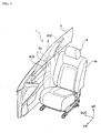
- Figure 1 is a perspective view of an interior of a compartment of a vehicle provided with an airbag apparatus when an airbag is inflated and deployed.
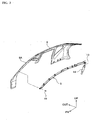
- Figure 2 is a schematic side view of the vehicle provided with the airbag apparatus when the airbag is inflated and deployed. Further, in each Figure, "UP” indicates an upper side, “FR” indicates a front side and “OUT” indicates an outer side in the vehicular width direction.
- an airbag apparatus 1 may include a curtain airbag 5 and a side airbag 7.
- the curtain airbag 5 may be inflated and deployed from a location proximate to an upper side of a side window area 2 along a pillar 4 or a side window area 2 towards a lower side.
- the side airbag 7 may be deployed from a location proximate to a lower side of the side window area 2 along an inner surface of the pillar 4 or a door 6.
- the pillar 4, the side window area 2 and the door 6 may generally form the vehicle compartment side surface 3.
- curtain airbag 5 When curtain airbag 5 is inflated and deployed, the curtain airbag 5 may downwardly extend from a roof side rail 8 or a front side pillar 8A (see Figure 3 ) in a curtain configuration to form a planar cushion in a band or "curtain" shape, which may be thin and relatively long in a front-and-rear direction, generally along an upper portion of the vehicle compartment side surface 3, thereby mainly protecting a head portion Pa or a neck portion Pb of a passenger P as shown in Figure 2 .
- the vehicle compartment side surface 3 may indicate a side surface at an inner side of the vehicle compartment formed by the side window area 2, the pillar 4 and the door 6.
- the side airbag 7 when the side airbag 7 is inflated and deployed, the side airbag 7 may form a generally planar cushion in a generally elliptical shape, which may be lengthened in an up-and-down direction, along the vehicle compartment side surface 3 about approximately a center portion. This location and shape may protect a waist portion (e.g., a belly portion) Pc and a chest portion Pd in addition to neck portion Pb of passenger P as seen in Figure 2 .
- a waist portion e.g., a belly portion
- Pd a chest portion Pd in addition to neck portion Pb of passenger P as seen in Figure 2 .
- both the curtain airbag 5 and the side airbag 7 When both the curtain airbag 5 and the side airbag 7 are inflated and deployed, they may be configured to be disposed between the passenger P sitting on a seat and the vehicle compartment side surface 3. Further, it may be established in a region where the curtain airbag 5 overlaps with the side airbag 7, the side airbag 7 may be positioned at a vehicular outer side compared to the curtain airbag 5.
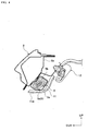
- Figure 3 is an exploded perspective view when the curtain airbag is installed.
- Figure 4 is a longitudinal cross-sectional view (perpendicular in the front-and-rear direction of the vehicle) when the curtain airbag is installed.
- the curtain airbag 5 may be rolled or folded into a relatively thin and long band and covered with a cover 5a.
- the curtain airbag 5 may be installed from a vehicular inner side in the roof side rail 8 or the front side pillar 8A using a fastening mechanism 10 such as a screw.
- the vehicular inner side of the curtain airbag 5 may be covered with a trim panel 11.
- reference numeral 12 of Figure 4 indicates an assist grip.
- an inflator 14 may be connected to a rear end of the curtain airbag 5 via a tube 13.
- the gas generated within the inflator 14 may be supplied via the tube 13 into the curtain airbag 5 and may forwardly flow within an air supply passage 5b, thereby inflating and deploying a pouch 5c, which may be rolled along an entire path in a front-and-rear direction.
- the air supply passage 5b may be elongated within the curtain airbag 5 in the front-and-rear direction.
- the pouch 5c supplied with the gas may penetrate through the cover 51 to contact and press a distal end portion 11 a of the trim 11, causing the distal end portion to be bent towards the vehicular inner side. Accordingly, the pouch 5c may be deployed toward a lower side of the window area while also spanning a gap between the distal end portion 11 a and a vehicle body side (e.g., the roof side rail 8, etc.).
- the pouch 5c may be rolled such that a vehicular outer side at the time of deployment becomes a diametrical inner side (rolling central axis), a force may be exerted upon a leading end of the pouch 5c towards the vehicular outer side. That is, because a rolling direction may be established as above, the pouch 5c may tend to be inflated and deployed along the vehicle compartment side surface 3.
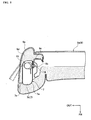
- Figure 5 is a flat cross-sectional view of a seat when a side airbag pouch is installed.
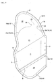
- Figure 6 is a side view when the side airbag pouch is deployed.
- Figure 7 is a side view seen opposite from Figure 6 when the side airbag pouch is deployed.
- the side airbag 7 may be installed within a seat back 9a or a side portion of a seat back 9a of a seat 9. More specifically, as shown in Figure 5 , a pouch 7b may be folded and accommodated within a case 7a and fixed to a side frame 9b of the seat 9 via a bracket 9c by using a fastening mechanism 16 such as a bolt or nut. A periphery of the pouch 7b may be covered by a cushion layer 9d or skin 9e so as not to be seen from the outside. The pouch 7b may be supplied with the gas generated by the inflator 15 that may push the case 7a along a tear line 7c, which is previously formed and frangible, to penetrate through the case 7a. Then, the pouch 7b may expand a side portion of the seat back 9a towards the vehicular outer side in a front deployed state to be inflated and deployed toward a front direction.
- a fastening mechanism 16 such as a bolt or nut.
- a periphery of the pouch 7b may be
- the pouch 7b of the side airbag 7 may be formed by stitching two or more base cloths 17 and 18 with a stitch or seam line (i.e., a seam) 19.
- a stitch or seam line i.e., a seam
- the pouch 7b may be inflated in a direction toward the upper end of the side window area to form a planar shape.
- side airbag 7 may be oriented such that base cloth 17 shown in Figure 6 orients toward the vehicular outer side and base cloth 18 shown in Figure 7 orients toward the vehicular inner side. That is, base cloth 17 may correspond to a vehicular outer side base cloth and base cloth 18 may correspond to a vehicular inner side base cloth.
- An entire periphery of the pouch 7b, except for an opening 7d for inserting the inflator 15 into the pouch 7b, may be stitched along a seam line 19 to form an inner space.
- This inner space may be divided by two stitch or seam lines 19b and 19c along the up-and-down direction (i.e ., the up-and-down direction in the inflated and deployed state shown in Figures 6 and 7 ) into three portions to thereby form a first lower side compartment portion 20, a second lower side compartment portion 21 and an upper side compartment portion 22 in an orderly manner from the bottom.
- Inflator 15 may have a relatively thin and long outer shape and may be disposed around opening 7d while a length direction of inflator 15 may be oriented toward the up-and-down direction.
- An exhaust port (not shown) of the inflator 15 may be exposed to the first lower side compartment portion 20, which may be formed at a lowermost side of the pouch 7b.
- the gas generated in the inflator 15 may first flow into the first lower side compartment portion 20.
- a communication port 23 may be formed at a boundary portion of the first lower side compartment portion 20 and the second lower side compartment portion 21. The gas may flow from an interior of the first lower side compartment portion 20 via the communication port 23 into the second lower side compartment portion 21.
- the stitch or seam line 19c may be formed of a boundary portion 24 for dividing the second lower side compartment portion 21 and the upper side compartment portion 22.
- This stitch or seam line 19c may be interrupted in a middle portion thereof to form a communication port 25 for communicating the second lower side compartment portion 21 with the upper side compartment portion 22.
- the gas in the second lower side compartment portion 21 may flow via the communication port 25 into the upper side compartment portion 22.
- the pouch 7b may not be inflated at a portion provided with the stitch or seam line 19c, the inflated pouch 7b may easily be bent at the boundary portion 24 provided with the stitch or seam line 24. That is, in selected embodiments, the boundary portion 24 may form a crease in the pouch 7b (side airbag 7) along seam line 24.
- two exhaust ports 26 and 27 may be formed in the base cloth 17 of the vehicular outer side.
- the exhaust port 26, corresponding to the second lower side compartment portion 21, may exhaust the gas from the second lower side compartment portion 21 to the outside of the pouch 7b.
- the exhaust port 27, corresponding to the upper side compartment portion 22, may exhaust the gas from the upper side compartment portion 22 to the outside of the pouch 7b.
- communication port 25 may be exposed toward exhaust port 27.
- an opening direction of the communication port 25 may be indicated by a wave line arrow OD.
- ends 28 of the stitch or seam lines 19c, which form the communication port 25 may be bent toward the exhaust port 27 side so as to be formed generally parallel to each other. From such a construction, when the pouch 7b is inflated, a flow path in a cylindrical shape may be formed at communication port 25 wherein the flow path may follow an elongation direction of a center line between the ends 28. Thus, it becomes possible to more precisely define an outflow direction of the gas in the communication port 25 (opening direction OD of the communication port 25).
- the communication port 25 may be opened toward the exhaust port 27, the gas flowing from the second lower side compartment portion 21 via the communication port 25 to the upper side compartment portion 22 may tend to be exhausted from the exhaust port 27.
- the exhaust port 27 may be formed in a slit shape intersecting with the opening direction OD, an end edge 27a at an upstream side of the exhaust port 27 and an end edge 27b at a downstream side may be spaced apart from each other and thus opened so as to be sterically displaced. That is, the end edge 27a and end edge 27b may become spaced apart to allow exhaust of the gas flowing in the opening direction OD. As such, it becomes easy to secure a relatively broader region of the opening.
- the exhaust ports 27 may be formed by a distance along the opening direction OD with respect to the communication port 25.
- a ratio of an amount of the gas exhausted from the exhaust port 27 and an amount of the gas flowing into the upper side compartment portion 22 may be set to be properly adjustable by a size of this distance, a direction of the slit, and an area or direction of the communication port 25 (a distance between the ends 28).
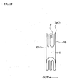
- Figures 8 and 9 illustrate an example of a folding order of the side airbag pouch in accordance with embodiments of the present invention.
- Figure 10 is a cross-sectional view of Figure 8 taken along a line X-X.
- the pouch 7b of the side airbag 7 may be folded and disposed in a predetermined housing position (within the seat back 9b in the present embodiment).
- a portion higher than dot and chain line A and a portion lower than a dot and chain line B of Figure 7 may be folded into a center portion C to be in a state shown in Figure 8 .
- an end E opposite to a disposing side D of the inflator 15 (not shown in Figure 8 ) may be folded in a bellow shape to be in a state shown in Figure 9 to thereby be accommodated within the case 7a (see Figure 5 ).
- an upper end F which forms the upper side compartment portion 22 of the pouch 7b, may be accommodated within the center portion C while being bent toward the vehicle compartment inner side.
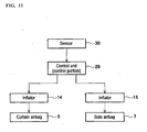
- FIG 11 is a control block diagram of the airbag apparatus in accordance with selected embodiments of the present invention.
- the airbag apparatus 1 may include a control unit (control portion) 29, a sensor 30, inflators 14 and 15, a curtain airbag 5 and a side airbag 7.
- a control unit control portion
- the sensor e.g ., an acceleration sensor
- the control unit 29 controls the inflators 14 and 15 to generate the gas
- the curtain airbag 5 and the side airbag 7 may be deployed.
- the timing to inflate and deploy curtain airbag 5 and side airbag 7 may be established to be the same or slightly different from each other.
- Figures 12A to 12D show a front view illustrating an operation of the airbag apparatus of the side collision in an order from 12A to 12D. Further, Figures 12A to 12D illustrate a case when the side window area 2 is either already opened at the time of the collision or broken during the collision. As such, the curtain airbag 5 and the side airbag 7 may partially move outwardly through the side window area 2 to the vehicular outer side.
- each of the inflators 14 and 15 may be controlled by the control unit 29 generating the gas. Then, as shown in Figure 12B , the curtain airbag 5 and the side airbag 7 may start to inflate and deploy. In certain embodiments, it may be preferred that curtain airbag 5 and side airbag 7 start inflating and deploying at approximately the same time.
- the inflated and deployed side airbag 7 may be disposed between the passenger P and vehicle compartment side surface 3. Further, the boundary portion 24 between the upper side compartment portion 22 and the second lower side compartment portion 21 of side airbag 7 (the pouch 7 thereof) may be configured to be in a position corresponding to the lower portion edge 2a of the side window area 2 while being inflated and deployed. Further, in such a state, the upper side compartment portion 22 of the side airbag 7 may not be fully inflated.
- the chest portion Pd of the passenger P may contact side airbag 7 and press side airbag 7.
- the boundary portion 24 of the second lower side compartment portion 21 and the upper side compartment portion 22 of the side airbag 7 may be in a position corresponding to the lower portion edge 2a of the side window area 2, the chest portion Pd of the passenger P may compresses the second lower side compartment portion 21 of the side airbag 7.
- the upper side compartment portion 22 may be inflated.
- the inflated and deployed curtain airbag 5 and side airbag 7 may be disposed between a vehicular outer side and the head portion Pa.
- the head portion Pa may be protected.
- airbag apparatus 1 including curtain airbag 5 and side airbag 7.
- the inflated and deployed side airbag 7 may contact the inflated and deployed curtain airbag 5 to suppress the movement of the curtain airbag 5.
- the curtain airbag 5 may be inflated and deployed from the roof side rail 8 ( see Figure 3 ) along the inner surface of the side window area 2 as the vehicle compartment side surface 3.
- the curtain airbag 5 might not be supported. This lack of support may cause the curtain airbag 5 to rotate around an upper portion support point ( e.g ., roof side rail 8) in the vehicular width direction.
- an upper portion support point e.g ., roof side rail 8
- the movement of the curtain airbag 5 may be suppressed by contacting an upper portion of side airbag 7 with a lower portion of curtain airbag 5.
- the protection to the passenger P may be improved.
- embodiments of the present invention may also be characterized in that a surface of the curtain airbag 5 slidably moves along a surface of the side airbag 7 (base clothes 17 and 18) and the movement of the curtain airbag 5 is suppressed by a friction of such sliding movement.
- the vehicular inner side base cloth 18 of the inflated and deployed side airbag 7 may contact the lower portion of the inflated and deployed curtain airbag 5.
- the curtain airbag 5 may be suppressed from moving toward the vehicular outer side.
- the protection may be improved by suppressing the movement of the curtain airbag 5 toward the vehicular outer side with side airbag 7.
- the crease formed by the boundary portion 24 of the second lower side compartment portion 21 and the upper side compartment portion 22 of the side airbag 7 may be disposed in a position corresponding to the lower portion edge 2a of the side window area 2 so that the upper side portion may bend at the crease to cover the lower portion edge 2a.
- the side airbag 7 may tend to fall with an angle towards the vehicular outer side in the opening portion of the side window area 2, it may becomes easy to obtain a state wherein the vehicular inner side base cloth 18 of the side airbag 7 contacts the lower portion of the curtain airbag 5.
- Exhaust port 27 for exhausting the gas towards the vehicular outer side is disposed corresponding to the upper side compartment portion 22, which may form the upper portion of the side airbag 7.
- a reaction force Fr of the gas exhaust may be exerted into the upper side compartment portion 22 towards the vehicular inner side. Accordingly, because the curtain airbag 5 may be pressed toward the vehicular inner side when contacting the upper portion (upper side compartment portion 22) of the side airbag 7 while the upper side compartment portion 22 is suppressed so as not to move excessively toward the vehicular outer side, the protection of the head portion Pa may be improved.
- the protection of the head portion Pa may be improved by curtain airbag 5.
- the head portion Pa may be protected by side airbag 7, because side airbag 7 may be deployed from the waist portion Pc along the chest portion Pd of the passenger P, compared to curtain airbag 5, side airbag 7 may tend to laterally fall down ( i.e. , slide downward) with respect to head portion Pa in a height of head portion Pa.
- curtain airbag 5 which may be disposed adjacent to head portion Pa.
- both the curtain airbag 5 and the side airbag 7 may partially come out from the opening portion of the side window area 2, because the curtain airbag 5 and the side airbag 7 may substantially be inflated and deployed within the vehicle compartment, the resulting protection may be increased compared to a alternatives where airbags are inflated and deployed (even partially) outside the vehicle.
- the movement of the curtain airbag 5 may be suppressed by contacting the inflated and deployed curtain airbag 5 with the inflated and deployed side airbag 7. As a result, it may become easy to dispose the curtain airbag 5 in a more desirable position, so the protection of passenger P (particularly the head portion Pa) may be improved.
- the movement of the curtain airbag 5 may be suppressed by contacting the inflated and deployed curtain airbag 5 with the inflated and deployed side airbag 7.
- the curtain airbag 5 may be suppressed from being pushed by the head portion Pa to move toward the vehicular outer side, the protection of the head portion Pa may be improved.
- the side airbag 7 may include the base cloths 17 and 18.
- the base cloth 17 may form the vehicular outer side in the inflated and deployed state.
- the base cloth 18 may form the vehicular inner side in the inflated and deployed state.
- the vehicular inner side base cloth 18 of the inflated and deployed side airbag 7 may contact the lower portion of the inflated and deployed curtain airbag 5.
- it may become easy to obtain a state where the leading end portion (upper end portion) of the side airbag 7 is disposed in the vehicular outer side from the curtain airbag 5, it may be easy to obtain a state where the movement of the curtain airbag 5 towards the vehicular outer side is suppressed by the side airbag 7.
- the boundary portion 24 of the upper side compartment portion 22 and the second lower side compartment portion 21 may be established in the side airbag 7 with the crease (along the lower portion edge) in a position corresponding to the lower portion edge 2a of the side window area 2 in the inflated and deployed state.
- the vehicular inner side base cloth 18 may contact the curtain airbag 5. For this reason, it may become easy to obtain a state where the movement of the curtain airbag 5 towards the vehicular outer side may be suppressed.
- the boundary portion 24 of the upper side compartment portion 22 and the second lower side compartment portion 21 may form the crease.
- Such a crease may be obtained by a relatively simple constitution.
- the boundary portion 24 i.e. , crease
- the boundary portion 24 may be obtained very simply by the stitch or seam line 19c.
- the exhaust port 27 for exhausting the gas towards the vehicular outer side is provided in the upper portion of the side airbag 7.
- the reaction force Fr of the gas exhaust may be exerted in the upper portion of the side airbag 7 towards the vehicular inner side
- an excessive movement of the upper portion of the side airbag 7 towards the vehicular outer side may be suppressed and a force may be generated for pressing the curtain airbag 5, which may contact the side airbag 7, to the vehicular inner side. Accordingly, the movement of the curtain airbag 5 towards the vehicular outer side may be more securely suppressed.
- the communication port 25 for communicating the upper side compartment portion 22 with the second lower side compartment portion 21 may be provided at the boundary portion 24 of the upper side compartment portion 22 and the second lower side compartment portion 21.
- the communication port 25 may be opened toward the exhaust port 27. By doing so, the gas flowing from the second lower side compartment portion 21 into the upper side compartment portion 22 may be effectively exhausted from the exhaust port 27. Thus, the effects from forming the exhaust port 27 may be more securely obtained.
- the upper side compartment portion 22 when the side airbag 7 is inflated and deployed, the upper side compartment portion 22 may correspond to the head portion Pa of the passenger P and the second lower side compartment 21 may correspond to the chest portion Pd of the passenger P.
- the gas in the second lower side compartment portion 21 may be introduced via the communication port 25 into the upper side compartment portion 22 by pressing the second lower side compartment portion 21 by the chest portion Pd of the passenger P. That is, because the chest portion Pd of the passenger P may first contact the second lower side compartment portion 21 of the side airbag 7, the upper side compartment portion 22 may be inflated at a more proper time based on the timing of pressing the second lower side compartment portion 21 by the chest portion Pd. Accordingly, the protection of the head portion Pa may be improved.
- a side airbag may suppresses the movement of the curtain airbag towards the vehicular outer side as described above, the side airbag may also suppress the movement towards the vehicular inner side as well.
- the specifications of the curtain airbag or side airbag such as the layouts, sizes, shapes and etc. may be properly varied.
- the side airbag may be installed in the vehicle compartment side wall such as the door or pillar or in the floor. Accordingly, the scope of the invention should be limited only by the attached claims.
Description
- The present invention relates to an airbag apparatus and methods. Aspects of the invention relate to an apparatus, to a method and to a vehicle.
- Japanese Laid-Open Patent Publication No.
2004-210012 Patent Document 1 "). - However, when the side window area is opened or broken due to a vehicle collision, the curtain airbag cannot be supported by the side window area. Accordingly, it becomes difficult to locate the curtain airbag in a desirable position.
- German patent application
DE-A1-4304152 discloses an airbag system having two air-bags fixed near the top and bottom side-window edges, so as to protect passengers from a side collision. The top and bottom bags move towards each other on inflation so as to bring mating faces into contact so as to form a sidewall with limited resistance to transverse forces. If the windowpane has been destroyed and there is no support outside the vehicle for the inflated wall formed by the airbags, the joint between the airbags does not withstand the force exerted by the occupant and the airbags are deformed outwardly in such a manner to protect the occupant from edge fragments of the windowpane. - United States patent application
US-A1-2004124615 discloses a side airbag device for protecting an occupant from a side impact applied to a body. The inside of the airbag is divided into an upper chamber and a lower chamber. A connecting portion is formed by joining the inside surfaces of the airbag. The flow of the inflation gas is distributed to the upper chamber and the lower chamber by the connecting portion. - Japanese patent application
JP-A-2004268682 - It is an aim of the present invention to address this issue and to improve upon known technology. Other aims and advantages of the invention will become apparent from the following description, claims and drawings.
- Aspects of the invention therefore provide an apparatus, a method and a vehicle as claimed in the appended claims.
- According to an aspect of the invention for which protection is sought, there is provided an airbag apparatus for a vehicle, comprising a curtain airbag arranged to be deployed from a first location proximate to an upper portion of a side window of the vehicle, and a side airbag arranged to be deployed from a second location proximate to a lower portion of the side window, wherein the curtain airbag is arranged to extend towards the lower portion of the side window when the curtain airbag is inflated, and wherein the side airbag is arranged to suppress a movement of the curtain airbag towards the vehicular outer side through contact when the side window is either opened or broken when the curtain airbag and the side airbag are inflated, the suppression of movement of the curtain airbag comprising exhausting gas from an exhaust port in an upper portion of the side airbag in a direction towards the vehicular outer side.
- In an embodiment, the side airbag comprises a vehicular outer side base cloth and a vehicular inner side base cloth. The vehicular inner side base cloth may be configured to contact a lower portion of the curtain airbag when the curtain and the side airbags are inflated.
- In an embodiment, the inner side base cloth is configured to suppress the movement of the lower portion of the curtain airbag through friction.
- In an embodiment, the side airbag comprises a seam, wherein the seam forms a boundary between an upper compartment and a lower compartment of the side airbag, the boundary being configured to be in a position corresponding to the lower edge of the side window area while being inflated and deployed.
- In an embodiment, the seam comprises a communication port configured to allow a gas from an inflator to flow from the lower compartment to the upper compartment.
- In an embodiment, the side airbag comprises a communication port to communicate between an upper compartment and a lower compartment of the side airbag. The communication port may be opened toward the exhaust port.
- According to a further aspect of the invention for which protection is sought, there is provided a method to construct an airbag assembly of a vehicle, the method comprising providing a curtain airbag to an upper portion of a side of the vehicle, providing a side airbag to a lower portion of a side of the vehicle and arranging the side airbag such that an upper portion of the side airbag suppresses movement of the curtain airbag towards an outer side of the vehicle through contact when the side and the curtain airbags are inflated and the side window is either opened or broken, the suppression of movement of the curtain airbag comprising exhausting gas from an exhaust port in an upper portion of the side airbag in a direction towards the vehicular outer side.
- In an embodiment, the suppression of movement of the curtain airbag further comprises friction between the side airbag contacting an outer side of the curtain airbag.
- The present invention will now be described, by way of example only, with reference to the accompanying drawings, in which:
-
Figure 1 is a perspective view of an interior of a compartment of a vehicle provided with an airbag apparatus in accordance with embodiments of the present invention shown with an airbag of the airbag apparatus inflated and deployed; -
Figure 2 is a schematic side view of a vehicle provided with the airbag apparatus ofFigure 1 ; -
Figure 3 is an exploded perspective view of a vehicle body side and a curtain airbag of an airbag apparatus in accordance with embodiments of the present invention; -
Figure 4 is a longitudinal cross-sectional view of the vehicle body side ofFigure 3 shown with the curtain airbag of the airbag apparatus installed; -
Figure 5 is a flat cross-sectional view of a seat having a side airbag of an airbag apparatus in accordance with embodiments of the present invention.; -
Figure 6 is a side view of a side airbag in accordance with embodiments of the present invention, shown with a side airbag pouch deployed; -
Figure 7 is an opposite side view of the side airbag ofFigure 6 ; -
Figure 8 illustrates an initial process of a folding order of a side airbag pouch of an airbag apparatus in accordance with embodiments of the present invention; -
Figure 9 illustrates a subsequent process of a folding order of a side airbag pouch of an airbag apparatus in accordance with embodiments of the present invention; -
Figure 10 is a cross-sectional view taken along a line X-X ofFigure 8 ; -
Figure 11 is a control block diagram for an airbag apparatus in accordance with embodiments of the present invention; and -
Figures 12A, 12B, 12C, and 12D are front views of a vehicle illustrating an operation of an airbag apparatus during a side collision in an order from 12A to 12D in accordance with embodiments of the present invention. -
Figures 1 to 12 illustrate an embodiment of the present invention.Figure 1 is a perspective view of an interior of a compartment of a vehicle provided with an airbag apparatus when an airbag is inflated and deployed.Figure 2 is a schematic side view of the vehicle provided with the airbag apparatus when the airbag is inflated and deployed. Further, in each Figure, "UP" indicates an upper side, "FR" indicates a front side and "OUT" indicates an outer side in the vehicular width direction. - As shown in
Figures 1 and2 , anairbag apparatus 1 may include acurtain airbag 5 and aside airbag 7. Thecurtain airbag 5 may be inflated and deployed from a location proximate to an upper side of aside window area 2 along apillar 4 or aside window area 2 towards a lower side. Theside airbag 7 may be deployed from a location proximate to a lower side of theside window area 2 along an inner surface of thepillar 4 or adoor 6. Thepillar 4, theside window area 2 and thedoor 6 may generally form the vehiclecompartment side surface 3. - First,
curtain airbag 5 will be explained with reference toFigures 3 and4 . Whencurtain airbag 5 is inflated and deployed, thecurtain airbag 5 may downwardly extend from aroof side rail 8 or afront side pillar 8A (seeFigure 3 ) in a curtain configuration to form a planar cushion in a band or "curtain" shape, which may be thin and relatively long in a front-and-rear direction, generally along an upper portion of the vehiclecompartment side surface 3, thereby mainly protecting a head portion Pa or a neck portion Pb of a passenger P as shown inFigure 2 . Here, the vehiclecompartment side surface 3 may indicate a side surface at an inner side of the vehicle compartment formed by theside window area 2, thepillar 4 and thedoor 6. - In contrast, when the
side airbag 7 is inflated and deployed, theside airbag 7 may form a generally planar cushion in a generally elliptical shape, which may be lengthened in an up-and-down direction, along the vehiclecompartment side surface 3 about approximately a center portion. This location and shape may protect a waist portion (e.g., a belly portion) Pc and a chest portion Pd in addition to neck portion Pb of passenger P as seen inFigure 2 . - When both the
curtain airbag 5 and theside airbag 7 are inflated and deployed, they may be configured to be disposed between the passenger P sitting on a seat and the vehiclecompartment side surface 3. Further, it may be established in a region where thecurtain airbag 5 overlaps with theside airbag 7, theside airbag 7 may be positioned at a vehicular outer side compared to thecurtain airbag 5. -
Figure 3 is an exploded perspective view when the curtain airbag is installed.Figure 4 is a longitudinal cross-sectional view (perpendicular in the front-and-rear direction of the vehicle) when the curtain airbag is installed. In the installed state, thecurtain airbag 5 may be rolled or folded into a relatively thin and long band and covered with acover 5a. Thecurtain airbag 5 may be installed from a vehicular inner side in theroof side rail 8 or thefront side pillar 8A using afastening mechanism 10 such as a screw. The vehicular inner side of thecurtain airbag 5 may be covered with atrim panel 11. Additionally,reference numeral 12 ofFigure 4 indicates an assist grip. - As shown, an inflator 14 may be connected to a rear end of the
curtain airbag 5 via atube 13. The gas generated within the inflator 14 may be supplied via thetube 13 into thecurtain airbag 5 and may forwardly flow within anair supply passage 5b, thereby inflating and deploying apouch 5c, which may be rolled along an entire path in a front-and-rear direction. Theair supply passage 5b may be elongated within thecurtain airbag 5 in the front-and-rear direction. Thepouch 5c supplied with the gas may penetrate through the cover 51 to contact and press adistal end portion 11 a of the trim 11, causing the distal end portion to be bent towards the vehicular inner side. Accordingly, thepouch 5c may be deployed toward a lower side of the window area while also spanning a gap between thedistal end portion 11 a and a vehicle body side (e.g., theroof side rail 8, etc.). - Because the
pouch 5c may be rolled such that a vehicular outer side at the time of deployment becomes a diametrical inner side (rolling central axis), a force may be exerted upon a leading end of thepouch 5c towards the vehicular outer side. That is, because a rolling direction may be established as above, thepouch 5c may tend to be inflated and deployed along the vehiclecompartment side surface 3. - Next, the
side airbag 7 is explained with reference toFigures 5 to 7 .Figure 5 is a flat cross-sectional view of a seat when a side airbag pouch is installed.Figure 6 is a side view when the side airbag pouch is deployed.Figure 7 is a side view seen opposite fromFigure 6 when the side airbag pouch is deployed. - As shown in
Figures 2 and5 , theside airbag 7 may be installed within a seat back 9a or a side portion of a seat back 9a of aseat 9. More specifically, as shown inFigure 5 , apouch 7b may be folded and accommodated within acase 7a and fixed to aside frame 9b of theseat 9 via abracket 9c by using afastening mechanism 16 such as a bolt or nut. A periphery of thepouch 7b may be covered by acushion layer 9d orskin 9e so as not to be seen from the outside. Thepouch 7b may be supplied with the gas generated by the inflator 15 that may push thecase 7a along atear line 7c, which is previously formed and frangible, to penetrate through thecase 7a. Then, thepouch 7b may expand a side portion of the seat back 9a towards the vehicular outer side in a front deployed state to be inflated and deployed toward a front direction. - As shown in
Figures 6 and7 , thepouch 7b of theside airbag 7 may be formed by stitching two ormore base cloths Figures 6 and7 ) to an inner portion of thepouch 7b, thepouch 7b may be inflated in a direction toward the upper end of the side window area to form a planar shape. When thepouch 7b is inflated and deployed,side airbag 7 may be oriented such thatbase cloth 17 shown inFigure 6 orients toward the vehicular outer side andbase cloth 18 shown inFigure 7 orients toward the vehicular inner side. That is,base cloth 17 may correspond to a vehicular outer side base cloth andbase cloth 18 may correspond to a vehicular inner side base cloth. - An entire periphery of the
pouch 7b, except for anopening 7d for inserting the inflator 15 into thepouch 7b, may be stitched along aseam line 19 to form an inner space. This inner space may be divided by two stitch orseam lines 19b and 19c along the up-and-down direction (i.e., the up-and-down direction in the inflated and deployed state shown inFigures 6 and7 ) into three portions to thereby form a first lowerside compartment portion 20, a second lowerside compartment portion 21 and an upperside compartment portion 22 in an orderly manner from the bottom. -
Inflator 15 may have a relatively thin and long outer shape and may be disposed aroundopening 7d while a length direction ofinflator 15 may be oriented toward the up-and-down direction. An exhaust port (not shown) of the inflator 15 may be exposed to the first lowerside compartment portion 20, which may be formed at a lowermost side of thepouch 7b. The gas generated in the inflator 15 may first flow into the first lowerside compartment portion 20. Acommunication port 23 may be formed at a boundary portion of the first lowerside compartment portion 20 and the second lowerside compartment portion 21. The gas may flow from an interior of the first lowerside compartment portion 20 via thecommunication port 23 into the second lowerside compartment portion 21. - The stitch or seam line 19c may be formed of a
boundary portion 24 for dividing the second lowerside compartment portion 21 and the upperside compartment portion 22. This stitch or seam line 19c may be interrupted in a middle portion thereof to form acommunication port 25 for communicating the second lowerside compartment portion 21 with the upperside compartment portion 22. The gas in the second lowerside compartment portion 21 may flow via thecommunication port 25 into the upperside compartment portion 22. - Because the
pouch 7b may not be inflated at a portion provided with the stitch or seam line 19c, theinflated pouch 7b may easily be bent at theboundary portion 24 provided with the stitch orseam line 24. That is, in selected embodiments, theboundary portion 24 may form a crease in thepouch 7b (side airbag 7) alongseam line 24. - Further, as shown, two
exhaust ports base cloth 17 of the vehicular outer side. Theexhaust port 26, corresponding to the second lowerside compartment portion 21, may exhaust the gas from the second lowerside compartment portion 21 to the outside of thepouch 7b. Theexhaust port 27, corresponding to the upperside compartment portion 22, may exhaust the gas from the upperside compartment portion 22 to the outside of thepouch 7b. - Thus, in selected embodiments,
communication port 25 may be exposed towardexhaust port 27. InFigure 6 , an opening direction of thecommunication port 25 may be indicated by a wave line arrow OD. Further, ends 28 of the stitch or seam lines 19c, which form thecommunication port 25, may be bent toward theexhaust port 27 side so as to be formed generally parallel to each other. From such a construction, when thepouch 7b is inflated, a flow path in a cylindrical shape may be formed atcommunication port 25 wherein the flow path may follow an elongation direction of a center line between the ends 28. Thus, it becomes possible to more precisely define an outflow direction of the gas in the communication port 25 (opening direction OD of the communication port 25). - As such, because the
communication port 25 may be opened toward theexhaust port 27, the gas flowing from the second lowerside compartment portion 21 via thecommunication port 25 to the upperside compartment portion 22 may tend to be exhausted from theexhaust port 27. In particular, in selected embodiments, because theexhaust port 27 may be formed in a slit shape intersecting with the opening direction OD, anend edge 27a at an upstream side of theexhaust port 27 and anend edge 27b at a downstream side may be spaced apart from each other and thus opened so as to be sterically displaced. That is, theend edge 27a andend edge 27b may become spaced apart to allow exhaust of the gas flowing in the opening direction OD. As such, it becomes easy to secure a relatively broader region of the opening. - Further, in selected embodiments, the
exhaust ports 27 may be formed by a distance along the opening direction OD with respect to thecommunication port 25. By doing so, with respect to the gas flowing from thecommunication port 25, a ratio of an amount of the gas exhausted from theexhaust port 27 and an amount of the gas flowing into the upperside compartment portion 22 may be set to be properly adjustable by a size of this distance, a direction of the slit, and an area or direction of the communication port 25 (a distance between the ends 28). -
Figures 8 and9 illustrate an example of a folding order of the side airbag pouch in accordance with embodiments of the present invention.Figure 10 is a cross-sectional view ofFigure 8 taken along a line X-X. - The
pouch 7b of theside airbag 7 may be folded and disposed in a predetermined housing position (within the seat back 9b in the present embodiment). When folding thepouch 7b, a portion higher than dot and chain line A and a portion lower than a dot and chain line B ofFigure 7 may be folded into a center portion C to be in a state shown inFigure 8 . Then, an end E opposite to a disposing side D of the inflator 15 (not shown inFigure 8 ) may be folded in a bellow shape to be in a state shown inFigure 9 to thereby be accommodated within thecase 7a (seeFigure 5 ). - In selected embodiments, as shown in
Figure 10 , an upper end F, which forms the upperside compartment portion 22 of thepouch 7b, may be accommodated within the center portion C while being bent toward the vehicle compartment inner side. By doing so, when thepouch 7b is inflated and deployed, because the upper end F (i.e., the upper portion of thepouch 7b) is unfolded toward the vehicular outer side, it is possible to more securely deploy thepouch 7b along the vehiclecompartment side surface 3. -
Figure 11 is a control block diagram of the airbag apparatus in accordance with selected embodiments of the present invention. Theairbag apparatus 1 may include a control unit (control portion) 29, asensor 30,inflators curtain airbag 5 and aside airbag 7. When a side collision or rollover is detected by a detect signal from the sensor (e.g., an acceleration sensor) 30, because thecontrol unit 29 controls theinflators curtain airbag 5 and theside airbag 7 may be deployed. At this time, the timing to inflate and deploycurtain airbag 5 andside airbag 7 may be established to be the same or slightly different from each other. -
Figures 12A to 12D show a front view illustrating an operation of the airbag apparatus of the side collision in an order from 12A to 12D. Further,Figures 12A to 12D illustrate a case when theside window area 2 is either already opened at the time of the collision or broken during the collision. As such, thecurtain airbag 5 and theside airbag 7 may partially move outwardly through theside window area 2 to the vehicular outer side. - In
Figure 12A , if the side collision of the vehicle with anarticle 31 is detected by the sensor 30 (seeFigure 11 ), then each of theinflators control unit 29 generating the gas. Then, as shown inFigure 12B , thecurtain airbag 5 and theside airbag 7 may start to inflate and deploy. In certain embodiments, it may be preferred thatcurtain airbag 5 andside airbag 7 start inflating and deploying at approximately the same time. - As shown in
Figure 12B , the inflated and deployedside airbag 7 may be disposed between the passenger P and vehiclecompartment side surface 3. Further, theboundary portion 24 between the upperside compartment portion 22 and the second lowerside compartment portion 21 of side airbag 7 (thepouch 7 thereof) may be configured to be in a position corresponding to thelower portion edge 2a of theside window area 2 while being inflated and deployed. Further, in such a state, the upperside compartment portion 22 of theside airbag 7 may not be fully inflated. - Further, if the collision proceeds as shown in
Figure 12C , because theside airbag 7 pushed by the vehicle compartment side surface 3 (door 6) approaches from a side direction to the passenger P, the chest portion Pd of the passenger P may contactside airbag 7 andpress side airbag 7. At this time, as described above, because theboundary portion 24 of the second lowerside compartment portion 21 and the upperside compartment portion 22 of theside airbag 7 may be in a position corresponding to thelower portion edge 2a of theside window area 2, the chest portion Pd of the passenger P may compresses the second lowerside compartment portion 21 of theside airbag 7. Thus, because the gas in the second lowerside compartment portion 21 flows via the communication port 25 (seeFigure 6 ) into the upperside compartment portion 22, the upperside compartment portion 22 may be inflated. - Also, if the collision proceeds as shown in
Figure 12D , although the head portion Pa of the passenger P relatively approaches the vehiclecompartment side surface 3, the inflated and deployedcurtain airbag 5 and side airbag 7 (upper side compartment portion 22) may be disposed between a vehicular outer side and the head portion Pa. - Accordingly, the head portion Pa may be protected. As can be seen from
Figure 12D , it should be understood that a portion of passenger P from the waist portion Pc to the head Pd portion of the passenger may be seamlessly protected byairbag apparatus 1 includingcurtain airbag 5 andside airbag 7. - Further, as shown in
Figure 12D , the inflated and deployedside airbag 7 may contact the inflated and deployedcurtain airbag 5 to suppress the movement of thecurtain airbag 5. Thecurtain airbag 5 may be inflated and deployed from the roof side rail 8 (seeFigure 3 ) along the inner surface of theside window area 2 as the vehiclecompartment side surface 3. However, if there is noside window area 2, then thecurtain airbag 5 might not be supported. This lack of support may cause thecurtain airbag 5 to rotate around an upper portion support point (e.g., roof side rail 8) in the vehicular width direction. Thus, a protection of the head portion Pa may be adversely affected depending on the circumstances surrounding a collision. - According to selected embodiments, the movement of the
curtain airbag 5 may be suppressed by contacting an upper portion ofside airbag 7 with a lower portion ofcurtain airbag 5. As such, because it may be easy to maintaincurtain airbag 5 in a more beneficial position, the protection to the passenger P may be improved. In such a case, it may be advantageous for the lower portion ofcurtain airbag 5 to be retained or supported by the upper portion ofside airbag 7. However, it may be advantageous forcurtain airbag 5 to be disposed in a more beneficial position for protecting the head portion Pa as it approaches the vehiclecompartment side surface 3. In this regard, embodiments of the present invention may also be characterized in that a surface of thecurtain airbag 5 slidably moves along a surface of the side airbag 7 (base clothes 17 and 18) and the movement of thecurtain airbag 5 is suppressed by a friction of such sliding movement. - Further, as shown in
Figure 12D , the vehicular innerside base cloth 18 of the inflated and deployedside airbag 7 may contact the lower portion of the inflated and deployedcurtain airbag 5. As such, thecurtain airbag 5 may be suppressed from moving toward the vehicular outer side. In a collision mode as shown inFigures 12A to 12D , because the head portion Pa may move toward vehicular outer side, the protection may be improved by suppressing the movement of thecurtain airbag 5 toward the vehicular outer side withside airbag 7. - Further, as described above, in selected embodiments, the crease formed by the
boundary portion 24 of the second lowerside compartment portion 21 and the upperside compartment portion 22 of theside airbag 7 may be disposed in a position corresponding to thelower portion edge 2a of theside window area 2 so that the upper side portion may bend at the crease to cover thelower portion edge 2a. As such, as shown inFigures 12B and 12C , because theside airbag 7 may tend to fall with an angle towards the vehicular outer side in the opening portion of theside window area 2, it may becomes easy to obtain a state wherein the vehicular innerside base cloth 18 of theside airbag 7 contacts the lower portion of thecurtain airbag 5. - Exhaust port 27 (see
Figure 6 ) for exhausting the gas towards the vehicular outer side is disposed corresponding to the upperside compartment portion 22, which may form the upper portion of theside airbag 7. Thus, a reaction force Fr of the gas exhaust may be exerted into the upperside compartment portion 22 towards the vehicular inner side. Accordingly, because thecurtain airbag 5 may be pressed toward the vehicular inner side when contacting the upper portion (upper side compartment portion 22) of theside airbag 7 while the upperside compartment portion 22 is suppressed so as not to move excessively toward the vehicular outer side, the protection of the head portion Pa may be improved. - In selected embodiments, the protection of the head portion Pa may be improved by
curtain airbag 5. Although the head portion Pa may be protected byside airbag 7, becauseside airbag 7 may be deployed from the waist portion Pc along the chest portion Pd of the passenger P, compared tocurtain airbag 5,side airbag 7 may tend to laterally fall down (i.e., slide downward) with respect to head portion Pa in a height of head portion Pa. Thus, it may be possible to improve the protection of the head portion Pa by usingcurtain airbag 5, which may be disposed adjacent to head portion Pa. - Further, to use an alternative mechanism to suppress movement of
curtain airbag 5 additional components may be required, resulting in a more complicated construction or a layout that may be restrictive. However, because the movement of thecurtain airbag 5 may be suppressed by effectively using theside airbag 7 to protect the waist portion Pc and the chest portion Pd of the passenger P, such construction issues are rare. As described above, because a cushion area may be formed seamlessly byairbags - Further, although both the
curtain airbag 5 and theside airbag 7 may partially come out from the opening portion of theside window area 2, because thecurtain airbag 5 and theside airbag 7 may substantially be inflated and deployed within the vehicle compartment, the resulting protection may be increased compared to a alternatives where airbags are inflated and deployed (even partially) outside the vehicle. - As described above, in selected embodiments, the movement of the
curtain airbag 5 may be suppressed by contacting the inflated and deployedcurtain airbag 5 with the inflated and deployedside airbag 7. As a result, it may become easy to dispose thecurtain airbag 5 in a more desirable position, so the protection of passenger P (particularly the head portion Pa) may be improved. - In particular, in selected embodiments, the movement of the
curtain airbag 5 may be suppressed by contacting the inflated and deployedcurtain airbag 5 with the inflated and deployedside airbag 7. By doing so, when the head portion Pa of the passenger P moves toward the vehicular outer side at the time of a collision, because thecurtain airbag 5 may be suppressed from being pushed by the head portion Pa to move toward the vehicular outer side, the protection of the head portion Pa may be improved. - Further, in selected embodiments, the
side airbag 7 may include thebase cloths base cloth 17 may form the vehicular outer side in the inflated and deployed state. Further, thebase cloth 18 may form the vehicular inner side in the inflated and deployed state. The vehicular innerside base cloth 18 of the inflated and deployedside airbag 7 may contact the lower portion of the inflated and deployedcurtain airbag 5. Thus, because it may become easy to obtain a state where the leading end portion (upper end portion) of theside airbag 7 is disposed in the vehicular outer side from thecurtain airbag 5, it may be easy to obtain a state where the movement of thecurtain airbag 5 towards the vehicular outer side is suppressed by theside airbag 7. - Further, in selected embodiments, the
boundary portion 24 of the upperside compartment portion 22 and the second lowerside compartment portion 21 may be established in theside airbag 7 with the crease (along the lower portion edge) in a position corresponding to thelower portion edge 2a of theside window area 2 in the inflated and deployed state. Thus, because the upper portion of theside airbag 7 may be bent from the crease (formed by the boundary portion 24) towards the vehicular outer side from the opening portion of theside window area 2, the vehicular innerside base cloth 18 may contact thecurtain airbag 5. For this reason, it may become easy to obtain a state where the movement of thecurtain airbag 5 towards the vehicular outer side may be suppressed. - In particular, the
boundary portion 24 of the upperside compartment portion 22 and the second lowerside compartment portion 21 may form the crease. Such a crease may be obtained by a relatively simple constitution. Particularly, the boundary portion 24 (i.e., crease) may be obtained very simply by the stitch or seam line 19c. - The
exhaust port 27 for exhausting the gas towards the vehicular outer side is provided in the upper portion of theside airbag 7. Thus, because the reaction force Fr of the gas exhaust may be exerted in the upper portion of theside airbag 7 towards the vehicular inner side, an excessive movement of the upper portion of theside airbag 7 towards the vehicular outer side may be suppressed and a force may be generated for pressing thecurtain airbag 5, which may contact theside airbag 7, to the vehicular inner side. Accordingly, the movement of thecurtain airbag 5 towards the vehicular outer side may be more securely suppressed. - Also, in selected embodiments, the
communication port 25 for communicating the upperside compartment portion 22 with the second lowerside compartment portion 21 may be provided at theboundary portion 24 of the upperside compartment portion 22 and the second lowerside compartment portion 21. Thecommunication port 25 may be opened toward theexhaust port 27. By doing so, the gas flowing from the second lowerside compartment portion 21 into the upperside compartment portion 22 may be effectively exhausted from theexhaust port 27. Thus, the effects from forming theexhaust port 27 may be more securely obtained. - Further, in selected embodiments, when the
side airbag 7 is inflated and deployed, the upperside compartment portion 22 may correspond to the head portion Pa of the passenger P and the secondlower side compartment 21 may correspond to the chest portion Pd of the passenger P. Thus, the gas in the second lowerside compartment portion 21 may be introduced via thecommunication port 25 into the upperside compartment portion 22 by pressing the second lowerside compartment portion 21 by the chest portion Pd of the passenger P. That is, because the chest portion Pd of the passenger P may first contact the second lowerside compartment portion 21 of theside airbag 7, the upperside compartment portion 22 may be inflated at a more proper time based on the timing of pressing the second lowerside compartment portion 21 by the chest portion Pd. Accordingly, the protection of the head portion Pa may be improved. - While the disclosure has been presented with respect to a limited number of embodiments, those skilled in the art, having benefit of this disclosure, will appreciate that other embodiments may be devised which do not depart from the scope of the present invention. For example, although a side airbag may suppresses the movement of the curtain airbag towards the vehicular outer side as described above, the side airbag may also suppress the movement towards the vehicular inner side as well. Further, the specifications of the curtain airbag or side airbag such as the layouts, sizes, shapes and etc. may be properly varied. For example, the side airbag may be installed in the vehicle compartment side wall such as the door or pillar or in the floor. Accordingly, the scope of the invention should be limited only by the attached claims.
Claims (10)
- An airbag apparatus (1) for a vehicle, comprising:a curtain airbag (5) arranged to be deployed from a first location proximate to an upper portion of a side window (2) of the vehicle; anda side airbag (7) arranged to be deployed from a second location proximate to a lower portion of the side window (2);wherein the curtain airbag (5) is arranged to extend towards the lower portion of the side window (2) when the curtain airbag (5) is inflated; andwherein the side airbag (7) is arranged to suppress a movement of the curtain airbag (5) towards the vehicular outer side through contact when the side window (2) is either opened or broken when the curtain and the side airbags (5,7) are inflated, the airbag apparatus (1) being characterized in that the suppression of movement of the curtain airbag (5) comprises exhausting gas from an exhaust port (27) in an upper portion of the side airbag (7) in a direction towards the vehicular outer side.
- The airbag apparatus (1) as claimed in claim 1, wherein the suppression of movement of the curtain airbag (5) further comprises friction between the side airbag (7) contacting an outer side of the curtain airbag (5).
- The airbag apparatus (1) as claimed in any preceding claim, wherein the side airbag (7) comprises a vehicular outer side base cloth (17) and a vehicular inner side base cloth (18) and wherein the vehicular inner side base cloth (18) is arranged to contact a lower portion of the curtain airbag (5) when the curtain and the side airbags (5, 7) are inflated.
- The airbag apparatus (1) as claimed in claim 3, wherein the inner side base cloth (18) is arranged to suppress the movement of the lower portion of the curtain airbag (5) through friction.
- The airbag apparatus (1) as claimed in any preceding claim, wherein the side airbag (7) comprises a seam (19), wherein the seam (19) forms a boundary (24) between an upper compartment (22) and a lower compartment (21) of the side airbag (7), the boundary (24) being configured to be in a position corresponding to the lower edge (2a) of the side window area (2) while being inflated and deployed.
- The airbag apparatus (1) as claimed in claim 5, wherein the seam (19) comprises a communication port (23) configured to allow a gas from an inflator (15) to flow from the lower compartment (21) to the upper compartment (22).
- The airbag apparatus (1) as claimed in claim 1, wherein the side airbag (7) comprises:a communication port (25) to communicate between an upper compartment (22) anda lower compartment (21) of the side airbag (7), and wherein the communication port (25) is opened toward the exhaust port (27).
- A method of constructing an airbag assembly for a vehicle, the method comprising:providing a curtain airbag (5) to an upper portion of a side of the vehicle;providing a side airbag (7) to a lower portion of a side of the vehicle; andarranging the side airbag (7) such that an upper portion of the side airbag (7) suppresses movement of the curtain airbag (5) towards an outer side of the vehicle through contact when the side and the curtain airbags (5, 7) are inflated and the side window (2) is either opened or broken, the method being characterized in that the suppression of movement of the curtain airbag (5) comprises exhausting gas from an exhaust port (27) in an upper portion of the side airbag (7) in a direction towards the vehicular outer side.
- The method as claimed in claim 8, the method being characterized in that the suppression of movement of the curtain airbag (5) further comprises friction between the side airbag (7) contacting an outer side of the curtain airbag (5).
- A vehicle having an airbag apparatus (1) as claimed in any of claims 1 to 7.
Applications Claiming Priority (1)
| Application Number | Priority Date | Filing Date | Title |
|---|---|---|---|
| JP2007328616A JP4600472B2 (en) | 2007-12-20 | 2007-12-20 | Airbag device |
Publications (3)
| Publication Number | Publication Date |
|---|---|
| EP2072345A2 EP2072345A2 (en) | 2009-06-24 |
| EP2072345A3 EP2072345A3 (en) | 2011-06-22 |
| EP2072345B1 true EP2072345B1 (en) | 2014-12-03 |
Family
ID=40456411
Family Applications (1)
| Application Number | Title | Priority Date | Filing Date |
|---|---|---|---|
| EP08172231.6A Expired - Fee Related EP2072345B1 (en) | 2007-12-20 | 2008-12-19 | Airbag apparatus and methods |
Country Status (5)
| Country | Link |
|---|---|
| US (1) | US7938440B2 (en) |
| EP (1) | EP2072345B1 (en) |
| JP (1) | JP4600472B2 (en) |
| KR (2) | KR20090067048A (en) |
| CN (1) | CN101462528B (en) |
Families Citing this family (54)
| Publication number | Priority date | Publication date | Assignee | Title |
|---|---|---|---|---|
| US8267424B2 (en) * | 2007-09-14 | 2012-09-18 | Toyota Motor East Japan, Inc. | Airbag |
| WO2010053138A1 (en) | 2008-11-05 | 2010-05-14 | 日本化薬株式会社 | Ignition system, gas generating device for airbag, and gas generating device for seatbelt pretensioner |
| DE102009016606B4 (en) * | 2009-04-08 | 2014-08-28 | Autoliv Development Ab | Height-adjustable motor vehicle seat with a side gas bag and motor vehicle with such a vehicle seat |
| DE102009031616A1 (en) * | 2009-07-03 | 2011-03-03 | GM Global Technology Operations, Inc., Detroit | Passenger safety device for vehicle, has air bag system which has three-zone air bag with zone, another zone and third zone |
| US8186708B2 (en) * | 2010-03-08 | 2012-05-29 | Ford Global Technologies, Llc | Asymmetric side airbag for improved head and neck protection |
| US8480124B2 (en) * | 2011-01-18 | 2013-07-09 | Autoliv Asp, Inc. | Seat bolster chamber |
| JP5401495B2 (en) * | 2011-03-17 | 2014-01-29 | 富士重工業株式会社 | Side airbag device, occupant protection device, and occupant protection method |
| JP5514758B2 (en) * | 2011-03-17 | 2014-06-04 | 富士重工業株式会社 | Side airbag device, occupant protection device, and occupant protection method |
| JP2013010381A (en) * | 2011-06-28 | 2013-01-17 | Nippon Plast Co Ltd | Vehicle occupant protection device |
| JP5626196B2 (en) * | 2011-12-19 | 2014-11-19 | トヨタ自動車株式会社 | Vehicle occupant protection device |
| JP2014076702A (en) | 2012-10-09 | 2014-05-01 | Toyota Motor Corp | Occupant protection device for vehicle |
| JP6004576B2 (en) * | 2012-11-28 | 2016-10-12 | 日本プラスト株式会社 | Airbag |
| JP5803948B2 (en) * | 2013-01-23 | 2015-11-04 | トヨタ自動車株式会社 | Side airbag device for vehicle |
| US8727374B1 (en) * | 2013-01-24 | 2014-05-20 | Ford Global Technologies, Llc | Vehicle seatback with side airbag deployment |
| US9415713B2 (en) | 2013-01-24 | 2016-08-16 | Ford Global Technologies, Llc | Flexible seatback system |
| US9409504B2 (en) | 2013-01-24 | 2016-08-09 | Ford Global Technologies, Llc | Flexible seatback system |
| US9399418B2 (en) | 2013-01-24 | 2016-07-26 | Ford Global Technologies, Llc | Independent cushion extension and thigh support |
| JP5972833B2 (en) * | 2013-06-10 | 2016-08-17 | 豊田合成株式会社 | Side airbag device |
| JP5954268B2 (en) * | 2013-07-04 | 2016-07-20 | トヨタ自動車株式会社 | Crew head restraint airbag device |
| JP2015051744A (en) * | 2013-09-09 | 2015-03-19 | トヨタ自動車株式会社 | Vehicular occupant-protector |
| US9315131B2 (en) | 2014-01-23 | 2016-04-19 | Ford Global Technologies, Llc | Suspension seat back and cushion system having an inner suspension panel |
| KR101718690B1 (en) * | 2014-02-12 | 2017-04-04 | 아우토리브 디벨롭먼트 아베 | Side curtain airbag for vehicle |
| US9421894B2 (en) | 2014-04-02 | 2016-08-23 | Ford Global Technologies, Llc | Vehicle seating assembly with manual independent thigh supports |
| JP6356788B2 (en) * | 2014-04-30 | 2018-07-11 | オートリブ ディベロップメント エービー | Side airbag device for vehicle |
| DE102014209664A1 (en) * | 2014-05-21 | 2015-11-26 | Ford Global Technologies, Llc | Side airbag device for vehicles |
| US9321423B2 (en) * | 2014-07-29 | 2016-04-26 | Ford Global Technologies, Llc | Roof mounted rear seat airbag safety cage |
| US9789790B2 (en) | 2014-10-03 | 2017-10-17 | Ford Global Technologies, Llc | Tuned flexible support member and flexible suspension features for comfort carriers |
| JP6225877B2 (en) * | 2014-10-22 | 2017-11-08 | トヨタ自動車株式会社 | Side airbag device for vehicle |
| US9566930B2 (en) | 2015-03-02 | 2017-02-14 | Ford Global Technologies, Llc | Vehicle seat assembly with side-impact airbag deployment mechanism |
| US10131313B2 (en) * | 2015-03-24 | 2018-11-20 | Trw Vehicle Safety Systems Inc. | Inflatable curtain restrictor |
| US10046682B2 (en) | 2015-08-03 | 2018-08-14 | Ford Global Technologies, Llc | Back cushion module for a vehicle seating assembly |
| US9849817B2 (en) | 2016-03-16 | 2017-12-26 | Ford Global Technologies, Llc | Composite seat structure |
| US10286818B2 (en) | 2016-03-16 | 2019-05-14 | Ford Global Technologies, Llc | Dual suspension seating assembly |
| JP6713306B2 (en) * | 2016-03-22 | 2020-06-24 | 株式会社Subaru | Occupant protection structure in the event of a vehicle side collision |
| US9994135B2 (en) | 2016-03-30 | 2018-06-12 | Ford Global Technologies, Llc | Independent cushion thigh support |
| US10220737B2 (en) | 2016-04-01 | 2019-03-05 | Ford Global Technologies, Llc | Kinematic back panel |
| US9889773B2 (en) | 2016-04-04 | 2018-02-13 | Ford Global Technologies, Llc | Anthropomorphic upper seatback |
| US9802512B1 (en) | 2016-04-12 | 2017-10-31 | Ford Global Technologies, Llc | Torsion spring bushing |
| US9682681B1 (en) * | 2016-05-31 | 2017-06-20 | Ford Global Technologies, Llc | Adaptive side torso airbag |
| US9845029B1 (en) | 2016-06-06 | 2017-12-19 | Ford Global Technologies, Llc | Passive conformal seat with hybrid air/liquid cells |
| US9849856B1 (en) | 2016-06-07 | 2017-12-26 | Ford Global Technologies, Llc | Side airbag energy management system |
| US9834166B1 (en) | 2016-06-07 | 2017-12-05 | Ford Global Technologies, Llc | Side airbag energy management system |
| US10377279B2 (en) | 2016-06-09 | 2019-08-13 | Ford Global Technologies, Llc | Integrated decking arm support feature |
| US10166895B2 (en) | 2016-06-09 | 2019-01-01 | Ford Global Technologies, Llc | Seatback comfort carrier |
| US10286824B2 (en) | 2016-08-24 | 2019-05-14 | Ford Global Technologies, Llc | Spreader plate load distribution |
| US10279714B2 (en) | 2016-08-26 | 2019-05-07 | Ford Global Technologies, Llc | Seating assembly with climate control features |
| US10391910B2 (en) | 2016-09-02 | 2019-08-27 | Ford Global Technologies, Llc | Modular assembly cross-tube attachment tab designs and functions |
| US10239431B2 (en) | 2016-09-02 | 2019-03-26 | Ford Global Technologies, Llc | Cross-tube attachment hook features for modular assembly and support |
| US10493941B2 (en) * | 2016-12-14 | 2019-12-03 | Ford Global Technologies, Llc | Door mounted airbag assembly with concave surface |
| US9914378B1 (en) | 2016-12-16 | 2018-03-13 | Ford Global Technologies, Llc | Decorative and functional upper seatback closeout assembly |
| US10596936B2 (en) | 2017-05-04 | 2020-03-24 | Ford Global Technologies, Llc | Self-retaining elastic strap for vent blower attachment to a back carrier |
| KR20210048612A (en) * | 2019-10-23 | 2021-05-04 | 현대자동차주식회사 | Side air bag for vehicle |
| JP7416659B2 (en) * | 2020-04-13 | 2024-01-17 | 株式会社Subaru | Occupant protection system |
| JP7380499B2 (en) * | 2020-09-29 | 2023-11-15 | トヨタ自動車株式会社 | Vehicle occupant protection device |
Family Cites Families (26)
| Publication number | Priority date | Publication date | Assignee | Title |
|---|---|---|---|---|
| JP2843099B2 (en) * | 1990-03-29 | 1999-01-06 | マツダ株式会社 | Energy absorption structure on the side of the vehicle |
| JP3119256B2 (en) * | 1991-11-22 | 2000-12-18 | タカタ株式会社 | Car occupant head protection device |
| JP3039089B2 (en) * | 1991-11-22 | 2000-05-08 | タカタ株式会社 | Car occupant head protection device |
| US5333899A (en) * | 1992-02-25 | 1994-08-02 | Volkswagen Ag | Side airbag safety arrangement for vehicle occupants |
| DE19542436A1 (en) * | 1995-11-14 | 1997-05-15 | Hs Tech & Design | Airbag device for motor vehicle |
| US5718450A (en) * | 1996-01-19 | 1998-02-17 | Takata, Inc. | Inflatable restraint system having a head/thorax cushion for side impact protection |
| US5913536A (en) * | 1996-02-07 | 1999-06-22 | Trw Vehicle Safety System Inc. | Air bag module |
| JPH09323605A (en) * | 1996-03-27 | 1997-12-16 | Morton Internatl Inc | Method of protecting occupant within cabin of automobile and method of folding air bag cushion |
| JP3365271B2 (en) * | 1997-09-19 | 2003-01-08 | 日産自動車株式会社 | Airbag device for automobile side collision |
| KR100352659B1 (en) * | 1997-09-19 | 2002-09-12 | 닛산 지도우샤 가부시키가이샤 | Apparatus for protecting crew member of automobile when collision of side portion thereof occurs |
| US6270113B1 (en) * | 1998-10-06 | 2001-08-07 | Breed Automotive Technology, Inc. | Side air bag system |
| US6371518B1 (en) * | 2000-02-23 | 2002-04-16 | Breed Automotive Technology, Inc. | Air bag, module and method of folding a side air bag or cushion |
| JP3835451B2 (en) * | 2001-06-08 | 2006-10-18 | 豊田合成株式会社 | Side airbag device |
| EP1852317A1 (en) * | 2001-07-03 | 2007-11-07 | Delphi Korea Corporation | Side airbag for automobile and method of folding the same |
| US6786505B2 (en) * | 2001-08-17 | 2004-09-07 | Takata Corporation | Airbag device |
| JP4161705B2 (en) * | 2002-12-19 | 2008-10-08 | タカタ株式会社 | Side airbag and side airbag device |
| JP3928951B2 (en) | 2002-12-27 | 2007-06-13 | 本田技研工業株式会社 | Crew protection device |
| JP4103633B2 (en) * | 2003-03-06 | 2008-06-18 | タカタ株式会社 | Side airbag device |
| US7413215B2 (en) * | 2003-09-17 | 2008-08-19 | Delphi Technologies, Inc. | Method and apparatus for providing an inflatable cushion for use with a vehicle door |
| JP4735020B2 (en) | 2005-04-21 | 2011-07-27 | トヨタ自動車株式会社 | Painting equipment |
| JP2007050847A (en) * | 2005-08-19 | 2007-03-01 | Toyota Motor Corp | Side collision airbag device |
| US7568722B2 (en) * | 2005-08-30 | 2009-08-04 | Honda Motor Co., Ltd. | Arrangement structure of air bag device |
| JP2007062599A (en) | 2005-08-31 | 2007-03-15 | Toyoda Gosei Co Ltd | Occupant protection device |
| US7455314B2 (en) * | 2005-11-04 | 2008-11-25 | Ford Global Technologies, Llc | Occupant protection system |
| JP4434193B2 (en) * | 2006-10-30 | 2010-03-17 | トヨタ自動車株式会社 | Side airbag device for vehicle |
| JP2008114631A (en) * | 2006-11-01 | 2008-05-22 | Toyota Motor Corp | Occupant protection device for vehicle |
-
2007
- 2007-12-20 JP JP2007328616A patent/JP4600472B2/en not_active Expired - Fee Related
-
2008
- 2008-12-11 KR KR1020080125630A patent/KR20090067048A/en not_active Application Discontinuation
- 2008-12-19 US US12/339,830 patent/US7938440B2/en active Active
- 2008-12-19 EP EP08172231.6A patent/EP2072345B1/en not_active Expired - Fee Related
- 2008-12-19 CN CN2008101864443A patent/CN101462528B/en not_active Expired - Fee Related
-
2011
- 2011-05-30 KR KR1020110051115A patent/KR101139988B1/en active IP Right Grant
Also Published As
| Publication number | Publication date |
|---|---|
| EP2072345A3 (en) | 2011-06-22 |
| CN101462528A (en) | 2009-06-24 |
| EP2072345A2 (en) | 2009-06-24 |
| KR101139988B1 (en) | 2012-05-02 |
| JP4600472B2 (en) | 2010-12-15 |
| US20090160166A1 (en) | 2009-06-25 |
| KR20110066125A (en) | 2011-06-16 |
| CN101462528B (en) | 2012-05-30 |
| US7938440B2 (en) | 2011-05-10 |
| JP2009149196A (en) | 2009-07-09 |
| KR20090067048A (en) | 2009-06-24 |
Similar Documents
| Publication | Publication Date | Title |
|---|---|---|
| EP2072345B1 (en) | Airbag apparatus and methods | |
| US10493940B2 (en) | Side airbag device | |
| EP1832475B1 (en) | Side air bag device for vehicle | |
| US9296357B2 (en) | Vehicle far-side airbag apparatus | |
| EP2889189B1 (en) | Vehicle side air bag device | |
| KR102004535B1 (en) | Rider protection | |
| EP3092157B1 (en) | Cost-effective use of one-piece woven fabric for curtain airbags | |
| US8894094B2 (en) | Curtain airbag for small overlap | |
| EP2876002B1 (en) | Side airbag device for vehicle | |
| US7350811B2 (en) | Side airbag apparatus | |
| JP4285167B2 (en) | Side airbag device | |
| US9566935B2 (en) | Double fold and roll cushions for IC | |
| CN113825678B (en) | Side airbag device and method for manufacturing side airbag device | |
| JP2009543731A (en) | Side curtain airbag with extended shoulder | |
| JP6396572B2 (en) | Side curtain airbags for vehicles | |
| CN111655550B (en) | Driver airbag | |
| WO2008059719A1 (en) | Crewman restraining device | |
| WO2007052756A1 (en) | Vehicle occupant restraint system | |
| US7832759B2 (en) | Side airbag module for a motor vehicle | |
| JP4432699B2 (en) | Airbag device | |
| CN109955822B (en) | Side airbag device for vehicle | |
| EP3296161B1 (en) | Vehicular curtain air bag device | |
| JP6551330B2 (en) | Vehicle occupant restraint system | |
| JP3881245B2 (en) | Airbag device for side impact of automobile | |
| CN109795440B (en) | Side airbag device for vehicle |
Legal Events
| Date | Code | Title | Description |
|---|---|---|---|
| PUAI | Public reference made under article 153(3) epc to a published international application that has entered the european phase |
Free format text: ORIGINAL CODE: 0009012 |
|
| AK | Designated contracting states |
Kind code of ref document: A2 Designated state(s): AT BE BG CH CY CZ DE DK EE ES FI FR GB GR HR HU IE IS IT LI LT LU LV MC MT NL NO PL PT RO SE SI SK TR |
|
| AX | Request for extension of the european patent |
Extension state: AL BA MK RS |
|
| PUAL | Search report despatched |
Free format text: ORIGINAL CODE: 0009013 |
|
| AK | Designated contracting states |
Kind code of ref document: A3 Designated state(s): AT BE BG CH CY CZ DE DK EE ES FI FR GB GR HR HU IE IS IT LI LT LU LV MC MT NL NO PL PT RO SE SI SK TR |
|
| AX | Request for extension of the european patent |
Extension state: AL BA MK RS |
|
| 17P | Request for examination filed |
Effective date: 20110906 |
|
| AKX | Designation fees paid |
Designated state(s): DE FR GB |
|
| 17Q | First examination report despatched |
Effective date: 20121011 |
|
| GRAP | Despatch of communication of intention to grant a patent |
Free format text: ORIGINAL CODE: EPIDOSNIGR1 |
|
| INTG | Intention to grant announced |
Effective date: 20140925 |
|
| RIC1 | Information provided on ipc code assigned before grant |
Ipc: B60R 21/00 20060101ALN20140916BHEP Ipc: B60R 21/207 20060101AFI20140916BHEP Ipc: B60R 21/213 20110101ALI20140916BHEP |
|
| GRAS | Grant fee paid |
Free format text: ORIGINAL CODE: EPIDOSNIGR3 |
|
| GRAA | (expected) grant |
Free format text: ORIGINAL CODE: 0009210 |
|
| AK | Designated contracting states |
Kind code of ref document: B1 Designated state(s): DE FR GB |
|
| REG | Reference to a national code |
Ref country code: GB Ref legal event code: FG4D |
|
| REG | Reference to a national code |
Ref country code: DE Ref legal event code: R096 Ref document number: 602008035655 Country of ref document: DE Effective date: 20150115 |
|
| REG | Reference to a national code |
Ref country code: DE Ref legal event code: R097 Ref document number: 602008035655 Country of ref document: DE |
|
| PLBE | No opposition filed within time limit |
Free format text: ORIGINAL CODE: 0009261 |
|
| STAA | Information on the status of an ep patent application or granted ep patent |
Free format text: STATUS: NO OPPOSITION FILED WITHIN TIME LIMIT |
|
| REG | Reference to a national code |
Ref country code: FR Ref legal event code: PLFP Year of fee payment: 8 |
|
| 26N | No opposition filed |
Effective date: 20150904 |
|
| REG | Reference to a national code |
Ref country code: FR Ref legal event code: PLFP Year of fee payment: 9 |
|
| REG | Reference to a national code |
Ref country code: FR Ref legal event code: PLFP Year of fee payment: 10 |
|
| PGFP | Annual fee paid to national office [announced via postgrant information from national office to epo] |
Ref country code: DE Payment date: 20191203 Year of fee payment: 12 |
|
| PGFP | Annual fee paid to national office [announced via postgrant information from national office to epo] |
Ref country code: FR Payment date: 20191115 Year of fee payment: 12 |
|
| PGFP | Annual fee paid to national office [announced via postgrant information from national office to epo] |
Ref country code: GB Payment date: 20191219 Year of fee payment: 12 |
|
| REG | Reference to a national code |
Ref country code: DE Ref legal event code: R119 Ref document number: 602008035655 Country of ref document: DE |
|
| GBPC | Gb: european patent ceased through non-payment of renewal fee |
Effective date: 20201219 |
|
| PG25 | Lapsed in a contracting state [announced via postgrant information from national office to epo] |
Ref country code: FR Free format text: LAPSE BECAUSE OF NON-PAYMENT OF DUE FEES Effective date: 20201231 |
|
| PG25 | Lapsed in a contracting state [announced via postgrant information from national office to epo] |
Ref country code: DE Free format text: LAPSE BECAUSE OF NON-PAYMENT OF DUE FEES Effective date: 20210701 Ref country code: GB Free format text: LAPSE BECAUSE OF NON-PAYMENT OF DUE FEES Effective date: 20201219 |