EP2072339A1 - Object fixing arrangement - Google Patents
Object fixing arrangement Download PDFInfo
- Publication number
- EP2072339A1 EP2072339A1 EP07025073A EP07025073A EP2072339A1 EP 2072339 A1 EP2072339 A1 EP 2072339A1 EP 07025073 A EP07025073 A EP 07025073A EP 07025073 A EP07025073 A EP 07025073A EP 2072339 A1 EP2072339 A1 EP 2072339A1
- Authority
- EP
- European Patent Office
- Prior art keywords
- fixing means
- engine cover
- fixing
- badge
- arrangement
- Prior art date
- Legal status (The legal status is an assumption and is not a legal conclusion. Google has not performed a legal analysis and makes no representation as to the accuracy of the status listed.)
- Granted
Links
- 239000002184 metal Substances 0.000 description 8
- 239000000463 material Substances 0.000 description 4
- 238000004519 manufacturing process Methods 0.000 description 3
- 230000001419 dependent effect Effects 0.000 description 2
- VYZAMTAEIAYCRO-UHFFFAOYSA-N Chromium Chemical compound [Cr] VYZAMTAEIAYCRO-UHFFFAOYSA-N 0.000 description 1
- 239000000853 adhesive Substances 0.000 description 1
- 230000001070 adhesive effect Effects 0.000 description 1
- 229910010293 ceramic material Inorganic materials 0.000 description 1
- 238000009434 installation Methods 0.000 description 1
- 238000000034 method Methods 0.000 description 1
- 238000000275 quality assurance Methods 0.000 description 1
Images
Classifications
-
- B—PERFORMING OPERATIONS; TRANSPORTING
- B60—VEHICLES IN GENERAL
- B60R—VEHICLES, VEHICLE FITTINGS, OR VEHICLE PARTS, NOT OTHERWISE PROVIDED FOR
- B60R13/00—Elements for body-finishing, identifying, or decorating; Arrangements or adaptations for advertising purposes
- B60R13/005—Manufacturers' emblems, name plates, bonnet ornaments, mascots or the like; Mounting means therefor
-
- B—PERFORMING OPERATIONS; TRANSPORTING
- B60—VEHICLES IN GENERAL
- B60R—VEHICLES, VEHICLE FITTINGS, OR VEHICLE PARTS, NOT OTHERWISE PROVIDED FOR
- B60R13/00—Elements for body-finishing, identifying, or decorating; Arrangements or adaptations for advertising purposes
-
- B—PERFORMING OPERATIONS; TRANSPORTING
- B60—VEHICLES IN GENERAL
- B60R—VEHICLES, VEHICLE FITTINGS, OR VEHICLE PARTS, NOT OTHERWISE PROVIDED FOR
- B60R13/00—Elements for body-finishing, identifying, or decorating; Arrangements or adaptations for advertising purposes
- B60R13/08—Insulating elements, e.g. for sound insulation
- B60R13/0876—Insulating elements, e.g. for sound insulation for mounting around heat sources, e.g. exhaust pipes
-
- B—PERFORMING OPERATIONS; TRANSPORTING
- B60—VEHICLES IN GENERAL
- B60R—VEHICLES, VEHICLE FITTINGS, OR VEHICLE PARTS, NOT OTHERWISE PROVIDED FOR
- B60R13/00—Elements for body-finishing, identifying, or decorating; Arrangements or adaptations for advertising purposes
- B60R13/08—Insulating elements, e.g. for sound insulation
- B60R13/0884—Insulating elements, e.g. for sound insulation for mounting around noise sources, e.g. air blowers
Definitions
- the present invention relates to an object fixing arrangement adapted to fixate a separate object to an engine cover.
- badges For example, most manufactures attach badges, for instance with the trademark of the manufacturer.
- a badge conveys a feeling, associated with a special brand, to the customer.
- the badges may have a wide range of shapes as well as designs including different materials. They have a range of shapes, for instance circular or quadratic, and different dimensions regarding thickness and area. Also, the badge may be in full colour or single-coloured.
- a cheaper brand or model may have a plastic badge, which may be inconceivable for a more exclusive brand or model. Instead, a metallic badge may be used for such brands or models. Exclusive models may have badges for example in chrome. Thus, the design of a badge may be varied indefinitely.
- the badge may be integrated in the engine cover or attach using an adhesive or a mechanical fastener on the engine cover.
- different types of badges have different requirements on the engine covers.
- each engine cover has to be adapted to each type of badge, resulting in a range of engine covers that is as large as the range of badges. It is obvious that this involves heavy expenditure.
- an objective of the invention is to solve or at least reduce the problems discussed above.
- an object fixing arrangement adapted to fixate a separate object to an engine cover.
- the object fixing arrangement comprises mutually matching fixing means, wherein said fixing means on said engine cover is adapted to receive at least two different types of fixing means on different objects.
- This arrangement allow fixing of objects with different types of fixing means on the engine cover, resulting in the possibility to use one type of cover to various objects regarding design, shape, and material etc.
- the manufacturer needs only one tool setting for producing engine covers for different objects. For example, a carmaker may be interested to attach about ten different types of objects with various designs, on comparable engine covers. Consequently, the object fixing arrangement may result in remarkably reduced investment costs.
- a badge support means may be a badge with integrated fixing means or an article or adapter, which holds a badge on the engine cover.
- said fixing means on said engine cover may be of at least two different types, each mutually matching to at least one type of fixing means on different objects. This in order to further increase the types of fixing means on objects, which may be attached to the engine cover.
- one type of engine cover may be used for several types of objects with different types of fixing means.
- each type of said fixing means on said engine cover may be mutually matching one type of fixing means on different objects. This in order to increase the exclusivity of the object.
- fixing means on the cover that mutually matches only one extraordinary type of fixing means on the object, it is difficult for example to rebadge low-priced vehicles to look like exclusive ones.
- At least one of said types of fixing means on said engine cover may be a recess adapted to receive at least one mutually matching fixing means on said object.
- one of said types of fixing means on said engine cover may be a through recess adapted to receive at least one mutually matching fixing means on said object.
- a recess and/or a through recess may be a simple fixing means which may be designed to receive different mechanical fasteners. If one recess/through recess is used to several different fixing means, the production of different engine cover types may be reduced.
- At least one of said types of fixing means on said engine cover may be a snap fit fixing means. This in order to simplify the production of the objects, which does not have to comprise a complicated fixing means. However, both the object and the engine cover may have snap fit fixing means that hook into each other.
- said fixing means are arranged asymmetrically. This results in that faulty installation of objects is prevented. Hence, quality assurance is simplified and production costs reduced.
- said fixing means fixes said plate detachably. This allows the consumer or the manufacturer to change the plate, if desired.
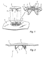
- Figure 1 is a perspective view of an engine cover and a badge with an object fixing arrangement comprising mutually matching fixing means.
- One part of the object fixing arrangement i.e. the one on the engine cover is magnified.
- Figure 2 is a side view of an engine cover and a plate attached together according to present invention.
- Figure 1 shows an engine cover 2 and an object 6 with an object fixing arrangement 1.
- the object fixing arrangement 1 comprises a first type of fixing means 3 and a second type of fixing means 4 on the engine cover 2 (only a part of the engine cover is shown), and fixing means 7 on the object 6, which are mutually matching to the first type of fixing means 3 on the engine cover 2.
- the object 6 is here a badge 6. However, it is not limited to be a badge. It may be any kind of article/object, for example, to fixate something to the outside of the engine cover.
- the snap fit fixing means 7 may be more complex than the one shown.
- the engine cover has an embedded area 8 where the two different types of fixing means 3, 4 are arranged.
- an embedded area is not necessary and the number of different fixing means is not limited to only two. It may be only one or more.
- the embedded area 8 is shown in more detail in the magnification, where three fixing means of the first type of fixing means 3 and five fixing means of the second type of fixing means 4 are shown.
- the number of fixing means of each type are not limited to this. It may be only one or several.
- the first type of fixing means 3 on the engine cover 2 are means to hold the snap fit fixing means 7 on the plastic badge 6 above.
- the second type of fixing means 4 arranged in a circle, may receive fixing means from a badge, made of for example metal, which may have other fixing means than for example a plastic badge (not shown).
- a metal badge may for instance have folding pins or the like.
- the fixing means on the metal badge are inserted through the openings/through recesses of the mutually matching second type of fixing means 4. After that, the fixing means on the badge (not shown) are folded towards the metal badge 6 in order to hold the metal badge in place.
- the size of the folding pins and their mutually matching through recesses may differ. For example, one of them may be thinner than the rest in order to prevent the badge to be fixed incorrectly.
- a stay part 5 is arranged in the centre of the portion with fixing means on the cover.
- the stay part may comprise a ring and a few protrusions. However, it is not limited to this. It may have any desired form.
- the stay part 5 may also be integrated in the badge instead of the engine cover 2.
- the plastic badge 6 in figure 1 is carried towards the engine cover 2 and its fixing means 3.
- the fixing means 7 on the badge 6 are inserted through the through recesses of the first mutually matching type of fixing means 3.
- the fixing means 7 on the badge 6 engage in the first type of fixing means 3 on the engine cover 2.
- the first type of fixing means 3, 7 on the cover 2 as well as on the badge 6 are asymmetrically arranged (as a Y) to prevent the badge 6 to be fixed incorrectly. Hence, there is only one way to fix the plate.
- FIG 2 shows the engine cover 2 and the badge 6 attached to each other via the object fixing arrangement 1, wherein the badge 6, made out of plastic, is fixed to the engine cover 2 by mutually matching fixing means 3, 7, in this case snap fit fixing means.
- the fixing means 7 on the badge 6 hook under the fixing means 3 on the engine cover 2.
- the different types of fixing means may be other than mentioned above.
- annular snap fit fixing means extending in the circumference of the badge 6 with mutually matching fixing means on the engine cover 2.
- the badge may have a screw arranged to it, which is inserted through a opening of the cover and fastened with a nut etc.
- An other possibility is to arrange snap fit fixing means on the engine cover 2, which engage in recesses and/or through recesses on the badge 6 or as shown in the figures, both the cover and the badge may have mutually matching snap fit function. All fixing means may fix said plate detachably.
- the object or badge may also be fixed on an adapter with fixing means with mutually matching fixing means on the engine cover.
- the badge may be made of some other material than plastic or metal, for instance a combination of metal and plastic or a ceramic material, or any other material known in the art.
Landscapes
- Engineering & Computer Science (AREA)
- Mechanical Engineering (AREA)
- Superstructure Of Vehicle (AREA)
- Cylinder Crankcases Of Internal Combustion Engines (AREA)
- Adornments (AREA)
- Vehicle Waterproofing, Decoration, And Sanitation Devices (AREA)
Abstract
Description
- The present invention relates to an object fixing arrangement adapted to fixate a separate object to an engine cover.
- Sometimes vehicle manufacturers want to attach specific information, for example about the engine, or other objects on engine covers. For example, most manufactures attach badges, for instance with the trademark of the manufacturer. A badge conveys a feeling, associated with a special brand, to the customer. Lately, there have been an increasing interest in under hood appearance of vehicles and consequently, importance of aforementioned badges has increased.
The badges may have a wide range of shapes as well as designs including different materials. They have a range of shapes, for instance circular or quadratic, and different dimensions regarding thickness and area. Also, the badge may be in full colour or single-coloured. A cheaper brand or model may have a plastic badge, which may be inconceivable for a more exclusive brand or model. Instead, a metallic badge may be used for such brands or models. Exclusive models may have badges for example in chrome. Thus, the design of a badge may be varied indefinitely. - The badge may be integrated in the engine cover or attach using an adhesive or a mechanical fastener on the engine cover. However, different types of badges have different requirements on the engine covers. Thus, each engine cover has to be adapted to each type of badge, resulting in a range of engine covers that is as large as the range of badges. It is obvious that this involves heavy expenditure. Thus, there is a need to reduce the cost and the product range.
- In view of the above, an objective of the invention is to solve or at least reduce the problems discussed above.
- These and other objects are achieved by an object fixing arrangement according to
claim 1. Preferred embodiments of the invention are defined in the dependent claims. - According to the present invention there is provided an object fixing arrangement adapted to fixate a separate object to an engine cover. The object fixing arrangement comprises mutually matching fixing means, wherein said fixing means on said engine cover is adapted to receive at least two different types of fixing means on different objects. This arrangement allow fixing of objects with different types of fixing means on the engine cover, resulting in the possibility to use one type of cover to various objects regarding design, shape, and material etc. Thus, the manufacturer needs only one tool setting for producing engine covers for different objects. For example, a carmaker may be interested to attach about ten different types of objects with various designs, on comparable engine covers. Consequently, the object fixing arrangement may result in remarkably reduced investment costs.
- Said object may be a badge support means, however it may also be a plate. A badge support means may be a badge with integrated fixing means or an article or adapter, which holds a badge on the engine cover.
- Preferably, said fixing means on said engine cover may be of at least two different types, each mutually matching to at least one type of fixing means on different objects. This in order to further increase the types of fixing means on objects, which may be attached to the engine cover. Thus, one type of engine cover may be used for several types of objects with different types of fixing means.
- Suitably, each type of said fixing means on said engine cover may be mutually matching one type of fixing means on different objects. This in order to increase the exclusivity of the object. By using fixing means on the cover that mutually matches only one extraordinary type of fixing means on the object, it is difficult for example to rebadge low-priced vehicles to look like exclusive ones.
- At least one of said types of fixing means on said engine cover may be a recess adapted to receive at least one mutually matching fixing means on said object.
- Alternatively, one of said types of fixing means on said engine cover may be a through recess adapted to receive at least one mutually matching fixing means on said object. A recess and/or a through recess may be a simple fixing means which may be designed to receive different mechanical fasteners. If one recess/through recess is used to several different fixing means, the production of different engine cover types may be reduced.
- At least one of said types of fixing means on said engine cover may be a snap fit fixing means. This in order to simplify the production of the objects, which does not have to comprise a complicated fixing means. However, both the object and the engine cover may have snap fit fixing means that hook into each other.
- Preferably, said fixing means are arranged asymmetrically. This results in that faulty installation of objects is prevented. Hence, quality assurance is simplified and production costs reduced.
Advantageously, according to the invention said fixing means fixes said plate detachably. This allows the consumer or the manufacturer to change the plate, if desired. - Generally, all terms used in the claims are to be interpreted according to their ordinary meaning in the technical field, unless explicitly defined otherwise herein. All references to "a/an/the [element, device, component, means, step, etc]" are to be interpreted openly as referring to at least one instance of said element, device, component, means, step, etc., unless explicitly stated otherwise. The steps of any method disclosed herein do not have to be performed in the exact order disclosed, unless explicitly stated. Other objectives, features and advantages of the present invention will appear from the following detailed disclosure, from the attached dependent claims as well as from the drawings.
- The above, as well as additional objects, features and advantages of the present invention, will be better understood through the following illustrative and non-limiting detailed description of preferred embodiments of the present invention, with reference to the appended drawings, where the same reference numerals will be used for similar elements.
-
Figure 1 is a perspective view of an engine cover and a badge with an object fixing arrangement comprising mutually matching fixing means. One part of the object fixing arrangement i.e. the one on the engine cover is magnified. -
Figure 2 is a side view of an engine cover and a plate attached together according to present invention. - All the figures are schematic, not necessarily to scale, and show only parts which are necessary in order to elucidate the invention, other parts being omitted or merely suggested.
- The present invention will be described in more detail below with reference to the accompanying schematic drawings, which for the purpose of illustration show a currently preferred embodiment.
Figure 1 shows anengine cover 2 and anobject 6 with anobject fixing arrangement 1. Theobject fixing arrangement 1 comprises a first type of fixing means 3 and a second type of fixing means 4 on the engine cover 2 (only a part of the engine cover is shown), and fixing means 7 on theobject 6, which are mutually matching to the first type of fixing means 3 on theengine cover 2. Theobject 6 is here abadge 6. However, it is not limited to be a badge. It may be any kind of article/object, for example, to fixate something to the outside of the engine cover. Thebadge 6, made of plastic, shows three simple snap fit fixing means 7. However, the snap fit fixing means 7 may be more complex than the one shown. The engine cover has an embeddedarea 8 where the two different types of fixing means 3, 4 are arranged. However, an embedded area is not necessary and the number of different fixing means is not limited to only two. It may be only one or more. The embeddedarea 8 is shown in more detail in the magnification, where three fixing means of the first type of fixing means 3 and five fixing means of the second type of fixing means 4 are shown. However, the number of fixing means of each type are not limited to this. It may be only one or several. - The first type of fixing means 3 on the
engine cover 2 are means to hold the snap fit fixing means 7 on theplastic badge 6 above. The second type of fixing means 4, arranged in a circle, may receive fixing means from a badge, made of for example metal, which may have other fixing means than for example a plastic badge (not shown). A metal badge may for instance have folding pins or the like. The fixing means on the metal badge are inserted through the openings/through recesses of the mutually matching second type of fixing means 4. After that, the fixing means on the badge (not shown) are folded towards themetal badge 6 in order to hold the metal badge in place. The size of the folding pins and their mutually matching through recesses may differ. For example, one of them may be thinner than the rest in order to prevent the badge to be fixed incorrectly. - To prevent a metal badge to be dented a
stay part 5 is arranged in the centre of the portion with fixing means on the cover. The stay part may comprise a ring and a few protrusions. However, it is not limited to this. It may have any desired form. Thestay part 5 may also be integrated in the badge instead of theengine cover 2. - The
plastic badge 6 infigure 1 is carried towards theengine cover 2 and its fixing means 3. The fixing means 7 on thebadge 6 are inserted through the through recesses of the first mutually matching type of fixing means 3. The fixing means 7 on thebadge 6 engage in the first type of fixing means 3 on theengine cover 2. - As is shown in
figure 1 the first type of fixing means 3, 7 on thecover 2 as well as on thebadge 6 are asymmetrically arranged (as a Y) to prevent thebadge 6 to be fixed incorrectly. Hence, there is only one way to fix the plate. -
Figure 2 shows theengine cover 2 and thebadge 6 attached to each other via theobject fixing arrangement 1, wherein thebadge 6, made out of plastic, is fixed to theengine cover 2 by mutually matching fixing means 3, 7, in this case snap fit fixing means. The fixing means 7 on thebadge 6 hook under the fixing means 3 on theengine cover 2. - Within the scope of the invention, the different types of fixing means may be other than mentioned above. For instance, annular snap fit fixing means extending in the circumference of the
badge 6 with mutually matching fixing means on theengine cover 2. The badge may have a screw arranged to it, which is inserted through a opening of the cover and fastened with a nut etc. An other possibility is to arrange snap fit fixing means on theengine cover 2, which engage in recesses and/or through recesses on thebadge 6 or as shown in the figures, both the cover and the badge may have mutually matching snap fit function. All fixing means may fix said plate detachably. Further, the object or badge may also be fixed on an adapter with fixing means with mutually matching fixing means on the engine cover. Also, the badge may be made of some other material than plastic or metal, for instance a combination of metal and plastic or a ceramic material, or any other material known in the art. - The invention has mainly been described above with reference to a few embodiments. However, as is readily appreciated by a person skilled in the art, other embodiments than the ones disclosed above are equally possible within the scope of the invention, as defined by the appended patent claims.
Claims (10)
- Object fixing arrangement (1) adapted to fixate a separate object (6) to an engine cover (2) characterised in that said object fixing arrangement (1) comprises mutually matching fixing means (3, 4, 7), wherein said fixing means (3, 4) on said engine cover (2) is adapted to receive at least two different types of fixing means (7) on different objects.
- Object fixing arrangement (1) according to claim 1, wherein said object (6) is a badge support means.
- Object fixing arrangement (1) according to claim 1, wherein said object (6) is a plate.
- Object fixing arrangement (1) according to any one of preceding claims, wherein said fixing means (3, 4) on said engine cover (2) is of at least two different types, each mutually matching to at least one type of fixing means (7) on different objects (6).
- Object fixing arrangement (1) according to any one of preceding claims, wherein each type of said fixing means (3, 4) on said engine cover (2) is mutually matching one type of fixing means (7) on different objects (6).
- Object fixing arrangement (1) according to any one of preceding claims, wherein at least one of said types of fixing means (3, 4) on said engine cover (2) is a recess adapted to receive at least one mutually matching fixing means (7) on said object (6).
- Object fixing arrangement (1) according to any one of preceding claims, wherein at least one of said types of fixing means (3, 4) on said engine cover (2) is a through recess adapted to receive at least one mutually matching fixing means (7) on said object (6).
- Object fixing arrangement according (1) to any one of preceding claims, wherein at least one of said types of fixing means (3, 4) on said engine cover (2) is a snap fit fixing means.
- Object fixing arrangement (1) according to any one of preceding claims, wherein said fixing means (3, 4, 7) are arranged asymmetrically.
- Object fixing arrangement (1) according to any of preceding claims, wherein said fixing means (3, 4, 7) fixes said object (6) detachably.
Priority Applications (2)
| Application Number | Priority Date | Filing Date | Title |
|---|---|---|---|
| AT07025073T ATE530387T1 (en) | 2007-12-22 | 2007-12-22 | OBJECT MOUNTING ARRANGEMENT |
| EP07025073A EP2072339B1 (en) | 2007-12-22 | 2007-12-22 | Object fixing arrangement |
Applications Claiming Priority (1)
| Application Number | Priority Date | Filing Date | Title |
|---|---|---|---|
| EP07025073A EP2072339B1 (en) | 2007-12-22 | 2007-12-22 | Object fixing arrangement |
Publications (2)
| Publication Number | Publication Date |
|---|---|
| EP2072339A1 true EP2072339A1 (en) | 2009-06-24 |
| EP2072339B1 EP2072339B1 (en) | 2011-10-26 |
Family
ID=39333132
Family Applications (1)
| Application Number | Title | Priority Date | Filing Date |
|---|---|---|---|
| EP07025073A Not-in-force EP2072339B1 (en) | 2007-12-22 | 2007-12-22 | Object fixing arrangement |
Country Status (2)
| Country | Link |
|---|---|
| EP (1) | EP2072339B1 (en) |
| AT (1) | ATE530387T1 (en) |
Cited By (1)
| Publication number | Priority date | Publication date | Assignee | Title |
|---|---|---|---|---|
| US10315589B2 (en) * | 2017-10-05 | 2019-06-11 | Ford Global Technologies, Llc | Reinforced vehicle component cover |
Citations (3)
| Publication number | Priority date | Publication date | Assignee | Title |
|---|---|---|---|---|
| US20060237995A1 (en) * | 2005-04-22 | 2006-10-26 | Decoma (Germany) Gmbh | Emblem for motor vehicle |
| DE202006009245U1 (en) * | 2006-06-09 | 2007-10-11 | Carcoustics Tech Center Gmbh | Airborne sound absorbing engine compartment trim for motor vehicles, in particular hood cladding |
| WO2007115722A1 (en) * | 2006-04-10 | 2007-10-18 | Dsm Ip Assets B.V. | Shaped part comprising a snap-fit element attached to a wall |
-
2007
- 2007-12-22 EP EP07025073A patent/EP2072339B1/en not_active Not-in-force
- 2007-12-22 AT AT07025073T patent/ATE530387T1/en not_active IP Right Cessation
Patent Citations (3)
| Publication number | Priority date | Publication date | Assignee | Title |
|---|---|---|---|---|
| US20060237995A1 (en) * | 2005-04-22 | 2006-10-26 | Decoma (Germany) Gmbh | Emblem for motor vehicle |
| WO2007115722A1 (en) * | 2006-04-10 | 2007-10-18 | Dsm Ip Assets B.V. | Shaped part comprising a snap-fit element attached to a wall |
| DE202006009245U1 (en) * | 2006-06-09 | 2007-10-11 | Carcoustics Tech Center Gmbh | Airborne sound absorbing engine compartment trim for motor vehicles, in particular hood cladding |
Cited By (1)
| Publication number | Priority date | Publication date | Assignee | Title |
|---|---|---|---|---|
| US10315589B2 (en) * | 2017-10-05 | 2019-06-11 | Ford Global Technologies, Llc | Reinforced vehicle component cover |
Also Published As
| Publication number | Publication date |
|---|---|
| ATE530387T1 (en) | 2011-11-15 |
| EP2072339B1 (en) | 2011-10-26 |
Similar Documents
| Publication | Publication Date | Title |
|---|---|---|
| US7527308B2 (en) | Modular bumper shell | |
| US10576783B2 (en) | Direct bolt simulated cap | |
| US7677650B2 (en) | Emblem for motor vehicle | |
| US8671601B2 (en) | System and method for mounting a badge on a vehicle | |
| CA2300560C (en) | Splash guard & method of making | |
| US20020030352A1 (en) | Air bag cover with ornament | |
| US9211850B2 (en) | License plate frame and method of use | |
| US6986918B2 (en) | System and method for facilitating customer appreciation | |
| US6637799B1 (en) | Modular sun visor and method of assembling same | |
| EP2072339A1 (en) | Object fixing arrangement | |
| TW202406773A (en) | Car radiator cover | |
| JPH02112792A (en) | Clock case | |
| CN105143999A (en) | Method and device for assembling movement to watch case | |
| US20020158175A1 (en) | Vehicle tissue box placement assembly | |
| US7309090B2 (en) | Bodywork element made of plastics having a grille integrally molded with said bodywork element | |
| EP3533354B1 (en) | Male member of snap fastener and snap fastener | |
| US20130093212A1 (en) | Vehicle mounting system and method of mounting an accessory to a vehicle | |
| JP2000050915A (en) | River with cap, mountable element with the rivet and mounting material with the element | |
| CN207297566U (en) | Buckle structure and automobile interior board mounting structure | |
| WO2007143396A2 (en) | Insert molded feature for airbag covers | |
| US20110127804A1 (en) | Trim ring having reinforced snap posts | |
| US20060125262A1 (en) | Method and apparatus for applying a decorative design to a door handle overlay | |
| US20030205890A1 (en) | Air bag containment apparatus | |
| JP2024508085A (en) | Supplementary parts for bags and methods of fixing supplementary parts to bags | |
| JP5684796B2 (en) | button |
Legal Events
| Date | Code | Title | Description |
|---|---|---|---|
| PUAI | Public reference made under article 153(3) epc to a published international application that has entered the european phase |
Free format text: ORIGINAL CODE: 0009012 |
|
| AK | Designated contracting states |
Kind code of ref document: A1 Designated state(s): AT BE BG CH CY CZ DE DK EE ES FI FR GB GR HU IE IS IT LI LT LU LV MC MT NL PL PT RO SE SI SK TR |
|
| AX | Request for extension of the european patent |
Extension state: AL BA HR MK RS |
|
| 17P | Request for examination filed |
Effective date: 20091228 |
|
| 17Q | First examination report despatched |
Effective date: 20100125 |
|
| AKX | Designation fees paid |
Designated state(s): AT BE BG CH CY CZ DE DK EE ES FI FR GB GR HU IE IS IT LI LT LU LV MC MT NL PL PT RO SE SI SK TR |
|
| GRAP | Despatch of communication of intention to grant a patent |
Free format text: ORIGINAL CODE: EPIDOSNIGR1 |
|
| RAP1 | Party data changed (applicant data changed or rights of an application transferred) |
Owner name: GM GLOBAL TECHNOLOGY OPERATIONS LLC |
|
| GRAS | Grant fee paid |
Free format text: ORIGINAL CODE: EPIDOSNIGR3 |
|
| GRAA | (expected) grant |
Free format text: ORIGINAL CODE: 0009210 |
|
| AK | Designated contracting states |
Kind code of ref document: B1 Designated state(s): AT BE BG CH CY CZ DE DK EE ES FI FR GB GR HU IE IS IT LI LT LU LV MC MT NL PL PT RO SE SI SK TR |
|
| REG | Reference to a national code |
Ref country code: GB Ref legal event code: FG4D |
|
| REG | Reference to a national code |
Ref country code: CH Ref legal event code: EP |
|
| REG | Reference to a national code |
Ref country code: IE Ref legal event code: FG4D |
|
| REG | Reference to a national code |
Ref country code: DE Ref legal event code: R096 Ref document number: 602007018149 Country of ref document: DE Effective date: 20111222 |
|
| REG | Reference to a national code |
Ref country code: NL Ref legal event code: VDEP Effective date: 20111026 |
|
| LTIE | Lt: invalidation of european patent or patent extension |
Effective date: 20111026 |
|
| REG | Reference to a national code |
Ref country code: AT Ref legal event code: MK05 Ref document number: 530387 Country of ref document: AT Kind code of ref document: T Effective date: 20111026 |
|
| PG25 | Lapsed in a contracting state [announced via postgrant information from national office to epo] |
Ref country code: LT Free format text: LAPSE BECAUSE OF FAILURE TO SUBMIT A TRANSLATION OF THE DESCRIPTION OR TO PAY THE FEE WITHIN THE PRESCRIBED TIME-LIMIT Effective date: 20111026 Ref country code: IS Free format text: LAPSE BECAUSE OF FAILURE TO SUBMIT A TRANSLATION OF THE DESCRIPTION OR TO PAY THE FEE WITHIN THE PRESCRIBED TIME-LIMIT Effective date: 20120226 Ref country code: BE Free format text: LAPSE BECAUSE OF FAILURE TO SUBMIT A TRANSLATION OF THE DESCRIPTION OR TO PAY THE FEE WITHIN THE PRESCRIBED TIME-LIMIT Effective date: 20111026 |
|
| PG25 | Lapsed in a contracting state [announced via postgrant information from national office to epo] |
Ref country code: PL Free format text: LAPSE BECAUSE OF FAILURE TO SUBMIT A TRANSLATION OF THE DESCRIPTION OR TO PAY THE FEE WITHIN THE PRESCRIBED TIME-LIMIT Effective date: 20111026 Ref country code: GR Free format text: LAPSE BECAUSE OF FAILURE TO SUBMIT A TRANSLATION OF THE DESCRIPTION OR TO PAY THE FEE WITHIN THE PRESCRIBED TIME-LIMIT Effective date: 20120127 Ref country code: SE Free format text: LAPSE BECAUSE OF FAILURE TO SUBMIT A TRANSLATION OF THE DESCRIPTION OR TO PAY THE FEE WITHIN THE PRESCRIBED TIME-LIMIT Effective date: 20111026 Ref country code: SI Free format text: LAPSE BECAUSE OF FAILURE TO SUBMIT A TRANSLATION OF THE DESCRIPTION OR TO PAY THE FEE WITHIN THE PRESCRIBED TIME-LIMIT Effective date: 20111026 Ref country code: PT Free format text: LAPSE BECAUSE OF FAILURE TO SUBMIT A TRANSLATION OF THE DESCRIPTION OR TO PAY THE FEE WITHIN THE PRESCRIBED TIME-LIMIT Effective date: 20120227 Ref country code: NL Free format text: LAPSE BECAUSE OF FAILURE TO SUBMIT A TRANSLATION OF THE DESCRIPTION OR TO PAY THE FEE WITHIN THE PRESCRIBED TIME-LIMIT Effective date: 20111026 Ref country code: LV Free format text: LAPSE BECAUSE OF FAILURE TO SUBMIT A TRANSLATION OF THE DESCRIPTION OR TO PAY THE FEE WITHIN THE PRESCRIBED TIME-LIMIT Effective date: 20111026 |
|
| PG25 | Lapsed in a contracting state [announced via postgrant information from national office to epo] |
Ref country code: CY Free format text: LAPSE BECAUSE OF FAILURE TO SUBMIT A TRANSLATION OF THE DESCRIPTION OR TO PAY THE FEE WITHIN THE PRESCRIBED TIME-LIMIT Effective date: 20111026 |
|
| PG25 | Lapsed in a contracting state [announced via postgrant information from national office to epo] |
Ref country code: EE Free format text: LAPSE BECAUSE OF FAILURE TO SUBMIT A TRANSLATION OF THE DESCRIPTION OR TO PAY THE FEE WITHIN THE PRESCRIBED TIME-LIMIT Effective date: 20111026 Ref country code: BG Free format text: LAPSE BECAUSE OF FAILURE TO SUBMIT A TRANSLATION OF THE DESCRIPTION OR TO PAY THE FEE WITHIN THE PRESCRIBED TIME-LIMIT Effective date: 20120126 Ref country code: DK Free format text: LAPSE BECAUSE OF FAILURE TO SUBMIT A TRANSLATION OF THE DESCRIPTION OR TO PAY THE FEE WITHIN THE PRESCRIBED TIME-LIMIT Effective date: 20111026 Ref country code: MC Free format text: LAPSE BECAUSE OF NON-PAYMENT OF DUE FEES Effective date: 20111231 Ref country code: SK Free format text: LAPSE BECAUSE OF FAILURE TO SUBMIT A TRANSLATION OF THE DESCRIPTION OR TO PAY THE FEE WITHIN THE PRESCRIBED TIME-LIMIT Effective date: 20111026 Ref country code: CZ Free format text: LAPSE BECAUSE OF FAILURE TO SUBMIT A TRANSLATION OF THE DESCRIPTION OR TO PAY THE FEE WITHIN THE PRESCRIBED TIME-LIMIT Effective date: 20111026 |
|
| REG | Reference to a national code |
Ref country code: CH Ref legal event code: PL |
|
| PG25 | Lapsed in a contracting state [announced via postgrant information from national office to epo] |
Ref country code: IT Free format text: LAPSE BECAUSE OF FAILURE TO SUBMIT A TRANSLATION OF THE DESCRIPTION OR TO PAY THE FEE WITHIN THE PRESCRIBED TIME-LIMIT Effective date: 20111026 Ref country code: RO Free format text: LAPSE BECAUSE OF FAILURE TO SUBMIT A TRANSLATION OF THE DESCRIPTION OR TO PAY THE FEE WITHIN THE PRESCRIBED TIME-LIMIT Effective date: 20111026 |
|
| PLBE | No opposition filed within time limit |
Free format text: ORIGINAL CODE: 0009261 |
|
| STAA | Information on the status of an ep patent application or granted ep patent |
Free format text: STATUS: NO OPPOSITION FILED WITHIN TIME LIMIT |
|
| REG | Reference to a national code |
Ref country code: IE Ref legal event code: MM4A |
|
| 26N | No opposition filed |
Effective date: 20120727 |
|
| PG25 | Lapsed in a contracting state [announced via postgrant information from national office to epo] |
Ref country code: LI Free format text: LAPSE BECAUSE OF NON-PAYMENT OF DUE FEES Effective date: 20111231 Ref country code: CH Free format text: LAPSE BECAUSE OF NON-PAYMENT OF DUE FEES Effective date: 20111231 Ref country code: IE Free format text: LAPSE BECAUSE OF NON-PAYMENT OF DUE FEES Effective date: 20111222 |
|
| REG | Reference to a national code |
Ref country code: DE Ref legal event code: R097 Ref document number: 602007018149 Country of ref document: DE Effective date: 20120727 |
|
| PG25 | Lapsed in a contracting state [announced via postgrant information from national office to epo] |
Ref country code: AT Free format text: LAPSE BECAUSE OF FAILURE TO SUBMIT A TRANSLATION OF THE DESCRIPTION OR TO PAY THE FEE WITHIN THE PRESCRIBED TIME-LIMIT Effective date: 20111026 |
|
| PG25 | Lapsed in a contracting state [announced via postgrant information from national office to epo] |
Ref country code: MT Free format text: LAPSE BECAUSE OF FAILURE TO SUBMIT A TRANSLATION OF THE DESCRIPTION OR TO PAY THE FEE WITHIN THE PRESCRIBED TIME-LIMIT Effective date: 20111026 |
|
| PG25 | Lapsed in a contracting state [announced via postgrant information from national office to epo] |
Ref country code: ES Free format text: LAPSE BECAUSE OF FAILURE TO SUBMIT A TRANSLATION OF THE DESCRIPTION OR TO PAY THE FEE WITHIN THE PRESCRIBED TIME-LIMIT Effective date: 20120206 |
|
| PG25 | Lapsed in a contracting state [announced via postgrant information from national office to epo] |
Ref country code: LU Free format text: LAPSE BECAUSE OF NON-PAYMENT OF DUE FEES Effective date: 20111222 |
|
| PG25 | Lapsed in a contracting state [announced via postgrant information from national office to epo] |
Ref country code: FI Free format text: LAPSE BECAUSE OF FAILURE TO SUBMIT A TRANSLATION OF THE DESCRIPTION OR TO PAY THE FEE WITHIN THE PRESCRIBED TIME-LIMIT Effective date: 20111026 |
|
| PG25 | Lapsed in a contracting state [announced via postgrant information from national office to epo] |
Ref country code: TR Free format text: LAPSE BECAUSE OF FAILURE TO SUBMIT A TRANSLATION OF THE DESCRIPTION OR TO PAY THE FEE WITHIN THE PRESCRIBED TIME-LIMIT Effective date: 20111026 |
|
| PG25 | Lapsed in a contracting state [announced via postgrant information from national office to epo] |
Ref country code: HU Free format text: LAPSE BECAUSE OF FAILURE TO SUBMIT A TRANSLATION OF THE DESCRIPTION OR TO PAY THE FEE WITHIN THE PRESCRIBED TIME-LIMIT Effective date: 20111026 |
|
| REG | Reference to a national code |
Ref country code: FR Ref legal event code: PLFP Year of fee payment: 9 |
|
| PGFP | Annual fee paid to national office [announced via postgrant information from national office to epo] |
Ref country code: GB Payment date: 20151216 Year of fee payment: 9 |
|
| PGFP | Annual fee paid to national office [announced via postgrant information from national office to epo] |
Ref country code: FR Payment date: 20151110 Year of fee payment: 9 |
|
| GBPC | Gb: european patent ceased through non-payment of renewal fee |
Effective date: 20161222 |
|
| REG | Reference to a national code |
Ref country code: FR Ref legal event code: ST Effective date: 20170831 |
|
| PG25 | Lapsed in a contracting state [announced via postgrant information from national office to epo] |
Ref country code: FR Free format text: LAPSE BECAUSE OF NON-PAYMENT OF DUE FEES Effective date: 20170102 |
|
| PG25 | Lapsed in a contracting state [announced via postgrant information from national office to epo] |
Ref country code: GB Free format text: LAPSE BECAUSE OF NON-PAYMENT OF DUE FEES Effective date: 20161222 |
|
| PGFP | Annual fee paid to national office [announced via postgrant information from national office to epo] |
Ref country code: DE Payment date: 20181211 Year of fee payment: 12 |
|
| REG | Reference to a national code |
Ref country code: DE Ref legal event code: R119 Ref document number: 602007018149 Country of ref document: DE |
|
| PG25 | Lapsed in a contracting state [announced via postgrant information from national office to epo] |
Ref country code: DE Free format text: LAPSE BECAUSE OF NON-PAYMENT OF DUE FEES Effective date: 20200701 |