EP2072292A1 - Energy harvesting device - Google Patents
Energy harvesting device Download PDFInfo
- Publication number
- EP2072292A1 EP2072292A1 EP07123828A EP07123828A EP2072292A1 EP 2072292 A1 EP2072292 A1 EP 2072292A1 EP 07123828 A EP07123828 A EP 07123828A EP 07123828 A EP07123828 A EP 07123828A EP 2072292 A1 EP2072292 A1 EP 2072292A1
- Authority
- EP
- European Patent Office
- Prior art keywords
- energy
- wheel
- capacitor
- mass
- radial
- Prior art date
- Legal status (The legal status is an assumption and is not a legal conclusion. Google has not performed a legal analysis and makes no representation as to the accuracy of the status listed.)
- Granted
Links
Images


Classifications
-
- B—PERFORMING OPERATIONS; TRANSPORTING
- B60—VEHICLES IN GENERAL
- B60C—VEHICLE TYRES; TYRE INFLATION; TYRE CHANGING; CONNECTING VALVES TO INFLATABLE ELASTIC BODIES IN GENERAL; DEVICES OR ARRANGEMENTS RELATED TO TYRES
- B60C23/00—Devices for measuring, signalling, controlling, or distributing tyre pressure or temperature, specially adapted for mounting on vehicles; Arrangement of tyre inflating devices on vehicles, e.g. of pumps or of tanks; Tyre cooling arrangements
- B60C23/02—Signalling devices actuated by tyre pressure
- B60C23/04—Signalling devices actuated by tyre pressure mounted on the wheel or tyre
- B60C23/0408—Signalling devices actuated by tyre pressure mounted on the wheel or tyre transmitting the signals by non-mechanical means from the wheel or tyre to a vehicle body mounted receiver
- B60C23/041—Means for supplying power to the signal- transmitting means on the wheel
-
- F—MECHANICAL ENGINEERING; LIGHTING; HEATING; WEAPONS; BLASTING
- F03—MACHINES OR ENGINES FOR LIQUIDS; WIND, SPRING, OR WEIGHT MOTORS; PRODUCING MECHANICAL POWER OR A REACTIVE PROPULSIVE THRUST, NOT OTHERWISE PROVIDED FOR
- F03G—SPRING, WEIGHT, INERTIA OR LIKE MOTORS; MECHANICAL-POWER PRODUCING DEVICES OR MECHANISMS, NOT OTHERWISE PROVIDED FOR OR USING ENERGY SOURCES NOT OTHERWISE PROVIDED FOR
- F03G7/00—Mechanical-power-producing mechanisms, not otherwise provided for or using energy sources not otherwise provided for
- F03G7/08—Mechanical-power-producing mechanisms, not otherwise provided for or using energy sources not otherwise provided for recovering energy derived from swinging, rolling, pitching or like movements, e.g. from the vibrations of a machine
- F03G7/081—Mechanical-power-producing mechanisms, not otherwise provided for or using energy sources not otherwise provided for recovering energy derived from swinging, rolling, pitching or like movements, e.g. from the vibrations of a machine recovering energy from moving road or rail vehicles, e.g. collecting vehicle vibrations in the vehicle tyres or shock absorbers
Definitions
- the present invention relates to a device and method for harvesting energy from a rotating wheel and for transferring the direction of energy from wheel vibrations, and in particular to a device and method for transferring energy from a radial to a tangential direction of the wheel.
- tyre pressure monitoring systems can comprise a pressure sensor and radio frequency transmitter at each wheel of a vehicle. These devices must be provided with electrical power and there are currently several known ways of doing this.
- One method of powering a device on a wheel is by "harvesting" vibration energy in the wheel.
- the energy harvested depends on the amplitude and frequency of the vibration of the wheel and this in turn depends on such factors as the type of wheel, the type of vehicle and the surface driven on. Therefore, such a method has limited performance.
- the present invention aims to overcome the above problems.
- an energy harvesting device for transferring vibrational energy from a radial to a tangential direction of a rotating wheel to which the device is attached, the device comprising:
- the problems related to large centripetal acceleration and thereby large, quasi-static deformation in the radial direction, which result in less optimal harvesting conditions, can be eliminated.
- This allows accurate and reliable energy harvesting of the energy from the radial vibrations to be performed in the tangential direction.
- the energy is transferred using the Coriolis force.
- an energy harvesting device comprises a frame 1 and a mass 2.
- the frame 1 and mass 2 are preferably made of one or more semiconductor materials for example silicon, arranged to move relative to one another.
- An alternative, but more expensive option, is to use materials, such as platinum or gold, which have a higher density than semiconductor materials.
- the harvested energy is proportional to weight, rather than to volume, therefore a mass 2 comprising such denser materials results in an improved device performance.
- section 17 illustrates a layer of the device formed from a different material to that of the frame 1 and mass 2.
- the frame 1 is preferably fixed in relation to a wheel to which it is connected, for example on the wheel rim, while the mass 2 is arranged so that it harvests energy from motion in a tangential direction of the wheel, as indicated by arrow 3 in Figures 1a and 1b .
- the frame is preferably attached to first and second wafers 4, and in this way the mass 2 is provided within a sealed cavity 5.
- the cavity 5 protects the mass 2 from contamination due to external debris or other environmental influences.
- a capacitor of the device has a first plate which is connected to the mass and a second plate which is connected to the frame, such that relative movement of the mass and the frame in the radial direction of the wheel alters the positions of the first and second plates of the capacitor relative to one another, thereby changing the capacitance of the capacitor.
- the relative movement of the first and second plates of the capacitor can comprise an increase or decrease in the separation distance (or gap) between the capacitive plates, or alternatively and preferably this distance can remain constant while relative movement causes the overlapping areas of the plates of the capacitors to vary, depending on the orientation of the device.
- a power management circuit can be employed to control the voltage/charge in a manner that is best suited for harvesting the energy. Such a circuit makes use of the electrical ports of the capacitors in such a manner that the generated electrical power can be used or stored in a battery for future use.
- the resonance frequency of the energy harvesting device in the radial and tangential directions of the wheel is preferably substantially equal in order to allow maximum efficiency in employing the energy harvesting device. Additionally, in the case of transferring energy from a radial to a tangential direction of the wheel, the effective mechanical damping coefficient must be lower in the radial direction than it is in the tangential direction.
- Figure 2a shows a plan view of an energy harvesting device in which the frame 1 is provided in the form of a plurality of frame members 6, 7.
- the frame members 6 are fixed to the mass 2 and act as support members via beams 8.
- the beam stiffness in the tangential and radial directions is substantially equal, for example the beams have a cross-section that is quadratic or that has circular symmetry.
- the tangential direction is again shown by the arrow 3, while the radial direction is out of the plane of the two-dimensional figure shown.
- Further frame members 7 are arranged to function as electrodes, and comprise a plurality of beams 9 which interlace beams 10 of the mass 2.
- the beam stiffness in the tangential and radial directions of each of the beams 8 is substantially equal.
- the beams 8, 9 or “fingers” of the frame 1 are arranged to allow a relatively large displacement in the radial and tangential direction.
- the tangential displacement varies a capacitance value measured between the interlacing beams 9 and 10, which form the electrodes of two capacitors.
- Such finger-structures are known. They can be manufactured from SOI-wafer (silicon-on-insulator). Deep reactive ion etching (DRIE) may be used to etch out the fingers of the silicon.
- DRIE Deep reactive ion etching
- Figure 2b shows an example of a translational energy harvester.
- the direction of tangential motion (harvesting direction) is again indicated by arrow 3, while the radial direction is again out of the plane shown.
- Beams 16 allow motion of a mass 2 in the tangential and radial directions with respect to a frame 1.
- One electrode of a capacitor is defined by patterned plates 18 arranged on the frame 1, and a second electrode is defined by patterned plates 19 on the mass 2.
- the capacitive electrode configuration is of a different type to that of Figure 2a , as an in-plane overlap motion in the tangential direction changes the capacitance.
- the capacitance will vary depending on the area of overlap of electrode plates 18 of the frame 1 and the corresponding electrode plates 19 of the mass 2.
- Figure 3a is an explanatory example of an energy harvesting device, where the x-direction represents the tangential acceleration of a point on a wheel rim to which the device is attached, and the ⁇ -direction represents the direction of centripetal acceleration of the wheel rim.
- masses 11, spring elements 12, and damper elements 13, which in parts are provided as transducers in a practical device, are shown.
- the capacitances change, as explained further below.
- the effects of both tangential and centripetal acceleration are exploited at the same time by employing a single mass 14, as shown in the example of Figure 3b .
- the capacitance is governed by the relative positions of two sets of electrodes 15.
- the energy harvesting device is preferably employed for energy harvesting on the rim of a wheel.
- the device is generally elongate, and is placed on the rim such that it is longer in the tangential direction than in the radial direction.
- Figure 4 shows an example of an energy harvesting device 20 positioned on a rim 21 of a wheel 22.
- the dimensions of the device 20 are substantially larger in the x-direction, which corresponds to the tangential direction of the wheel 22 when the device 20 is in the position shown, than in the ⁇ -direction, which corresponds to the radial direction.
- the Coriolis force is used.
- the energy harvesting can be modelled as a dissipative damper.
- K x and K y are the spring stiffness in the tangential and radial directions of the wheel, respectively
- ⁇ x and ⁇ y are the resonance frequencies in the tangential and radial directions of the wheel
- Q x and Q y are the Q-factors of the mechanical system in the tangential and radial directions of the wheel
- ⁇ wheel is the angular velocity of the wheel.
- the wheel rotation axis is normal to both
- the system can be optimised so that vibrational energy in the radial direction is harvested through the damper in a tangential direction.
- the Q-factor of the system in each direction is the Q-factor of the system in each direction.
- a lower Q-factor is required in the tangential direction than that required in the radial direction.
- the Q-factor of the mechanical system should be relatively low in the tangential direction.
- the Q-factor in the radial direction should be relatively high.
- the Q-factor in the radial direction is preferably controlled by viscous damping (gas in the cavity). This means that the Q-factor can be made large by using low pressure or a vacuum in the cavity.
- the effective Q-factor in the tangential direction will be a function of the viscous damping and electrostatic force/damping coming from the capacitor. When energy is extracted from the capacitor, it is seen as a loss/damping from a mechanical point of view.
Landscapes
- Engineering & Computer Science (AREA)
- Chemical & Material Sciences (AREA)
- Combustion & Propulsion (AREA)
- Mechanical Engineering (AREA)
- General Engineering & Computer Science (AREA)
- Micromachines (AREA)
Abstract

Description
- The present invention relates to a device and method for harvesting energy from a rotating wheel and for transferring the direction of energy from wheel vibrations, and in particular to a device and method for transferring energy from a radial to a tangential direction of the wheel.
- It is becoming more and more common for vehicles to have monitoring systems requiring devices such as sensors and transducers to be located at the wheels of a vehicle. For example, tyre pressure monitoring systems can comprise a pressure sensor and radio frequency transmitter at each wheel of a vehicle. These devices must be provided with electrical power and there are currently several known ways of doing this.
- One method of powering a device on a wheel is by "harvesting" vibration energy in the wheel. The energy harvested depends on the amplitude and frequency of the vibration of the wheel and this in turn depends on such factors as the type of wheel, the type of vehicle and the surface driven on. Therefore, such a method has limited performance.
- One disadvantage to harvesting energy from radial vibrations of a rotating wheel is that such vibrations are effectively superimposed on a quasi-static centripetal acceleration, the effects of which are often far greater than those of the vibrations, making the harvesting of energy from the radial vibrations complex. In practice, large DC centripetal acceleration levels exist on top of small vibrations, thus any energy harvesting device must meet the requirement of allowing for large static displacements, whilst still being very sensitive to small displacements. This is problematic when employing, for example, an electrostatic transducer element that utilises a change in capacitance, or a piezoelectric transducer.
- The present invention aims to overcome the above problems.
- According to the present invention there is provided an energy harvesting device for transferring vibrational energy from a radial to a tangential direction of a rotating wheel to which the device is attached, the device comprising:
- a mass, positioned within and arranged to be moveable relative to, a frame;
- a capacitor, a first plate of which is connected to the mass and a second plate of which is connected to the frame, such that relative movement of the mass and the frame in the tangential direction of the wheel alters the positions of the first and second plates of the capacitor relative to one another, thereby changing the capacitance of the capacitor; and
- harvesting means arranged to harvest electrical energy in the tangential direction from the change in capacitance of the capacitor, the electrical energy comprising energy transferred, owing to the Coriolis force acting on the rotating wheel, from the radial to the tangential direction thereof.
- By transferring power from the radial vibrations to the tangential direction, the problems related to large centripetal acceleration and thereby large, quasi-static deformation in the radial direction, which result in less optimal harvesting conditions, can be eliminated. This allows accurate and reliable energy harvesting of the energy from the radial vibrations to be performed in the tangential direction. The energy is transferred using the Coriolis force. In a rotating coordinate system, such as a wheel, the Coriolis acceleration (force) is given as a = 2Ω×v, where a is the acceleration as seen from the rotating coordinate system, v is the velocity as seen from the rotating coordinate system, and Ω is the wheel rotation speed.
- The invention will now be described in detail with reference to the accompanying drawings, in which:
-
Figures 1 a and 1b show an energy harvesting device according to the present invention; -
Figure 2a shows a plan view of a further embodiment of an energy harvesting device according to the present invention; -
Figure 2b shows a plan view of a further embodiment of an energy harvesting device according to the present invention; -
Figure 3a shows a schematic example of an energy harvesting device according to the present invention; -
Figure 3b shows a further schematic example of an energy harvesting device according to the present invention; and -
Figure 4 shows an example of an energy harvesting device according to the present invention positioned on a rim of a wheel. - Referring to
Figures 1a and 1b , an energy harvesting device comprises aframe 1 and amass 2. Theframe 1 andmass 2 are preferably made of one or more semiconductor materials for example silicon, arranged to move relative to one another. An alternative, but more expensive option, is to use materials, such as platinum or gold, which have a higher density than semiconductor materials. The harvested energy is proportional to weight, rather than to volume, therefore amass 2 comprising such denser materials results in an improved device performance. InFigure 1b ,section 17 illustrates a layer of the device formed from a different material to that of theframe 1 andmass 2. - The
frame 1 is preferably fixed in relation to a wheel to which it is connected, for example on the wheel rim, while themass 2 is arranged so that it harvests energy from motion in a tangential direction of the wheel, as indicated byarrow 3 inFigures 1a and 1b . The frame is preferably attached to first andsecond wafers 4, and in this way themass 2 is provided within a sealedcavity 5. Thecavity 5 protects themass 2 from contamination due to external debris or other environmental influences. - A capacitor of the device has a first plate which is connected to the mass and a second plate which is connected to the frame, such that relative movement of the mass and the frame in the radial direction of the wheel alters the positions of the first and second plates of the capacitor relative to one another, thereby changing the capacitance of the capacitor.
- The relative movement of the first and second plates of the capacitor can comprise an increase or decrease in the separation distance (or gap) between the capacitive plates, or alternatively and preferably this distance can remain constant while relative movement causes the overlapping areas of the plates of the capacitors to vary, depending on the orientation of the device.
- Energy harvesting, as an example, can be achieved as follows. For a given voltage V, or given charge, q, the energy of the capacitor (E=1/2·C·V2=1/2·C-1·q2) will vary depending on the capacitance, C. By applying a given voltage or charge, and then moving one electrode, the capacitance is changed. Therefore, the mechanical power has been used to change the electrical energy level, E=1/2·CV2. A power management circuit can be employed to control the voltage/charge in a manner that is best suited for harvesting the energy. Such a circuit makes use of the electrical ports of the capacitors in such a manner that the generated electrical power can be used or stored in a battery for future use.
- The resonance frequency of the energy harvesting device in the radial and tangential directions of the wheel is preferably substantially equal in order to allow maximum efficiency in employing the energy harvesting device. Additionally, in the case of transferring energy from a radial to a tangential direction of the wheel, the effective mechanical damping coefficient must be lower in the radial direction than it is in the tangential direction.
-
Figure 2a shows a plan view of an energy harvesting device in which theframe 1 is provided in the form of a plurality offrame members frame members 6 are fixed to themass 2 and act as support members viabeams 8. The beam stiffness in the tangential and radial directions is substantially equal, for example the beams have a cross-section that is quadratic or that has circular symmetry. The tangential direction is again shown by thearrow 3, while the radial direction is out of the plane of the two-dimensional figure shown. -
Further frame members 7 are arranged to function as electrodes, and comprise a plurality ofbeams 9 which interlacebeams 10 of themass 2. The beam stiffness in the tangential and radial directions of each of thebeams 8 is substantially equal. Thebeams frame 1 are arranged to allow a relatively large displacement in the radial and tangential direction. The tangential displacement varies a capacitance value measured between theinterlacing beams -
Figure 2b shows an example of a translational energy harvester. The direction of tangential motion (harvesting direction) is again indicated byarrow 3, while the radial direction is again out of the plane shown.Beams 16 allow motion of amass 2 in the tangential and radial directions with respect to aframe 1. One electrode of a capacitor is defined by patternedplates 18 arranged on theframe 1, and a second electrode is defined by patternedplates 19 on themass 2. Here the capacitive electrode configuration is of a different type to that ofFigure 2a , as an in-plane overlap motion in the tangential direction changes the capacitance. As can be understood fromFigure 2b , the capacitance will vary depending on the area of overlap ofelectrode plates 18 of theframe 1 and thecorresponding electrode plates 19 of themass 2. -
Figure 3a is an explanatory example of an energy harvesting device, where the x-direction represents the tangential acceleration of a point on a wheel rim to which the device is attached, and the γ-direction represents the direction of centripetal acceleration of the wheel rim. Here, masses 11,spring elements 12, anddamper elements 13, which in parts are provided as transducers in a practical device, are shown. As each mass 11 moves due to the movement of the rotating wheel rim, the capacitances change, as explained further below. The effects of both tangential and centripetal acceleration are exploited at the same time by employing asingle mass 14, as shown in the example ofFigure 3b . - Referring to
Figure 3b , the capacitance is governed by the relative positions of two sets ofelectrodes 15. The capacitance for each set of electrodes is defined as follows:
where C is the capacitance, ε is the permittivity, "gap" is the initial distance between the electrodes, A is area of the capacitive plates and x is the distance the electrodes have moved relative to one another due to movement of themass 2. The change in capacitance is calculated as: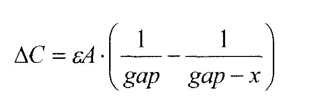
- In order to transfer the maximum amount of energy, a relatively high change in capacitance is required, therefore the initial gap between the electrodes of the relevant capacitor should be small. This is also true for the capacitors indicated in
Figure 2a , but here the area of the capacitive elements or plates, A, effectively changes as the relative positions of the two plates of the capacitor, and hence the area of overlap, change.Figure 2b works in the same manner, but here the capacitance will also depend upon the gap change x. During rotation of the tyre the centripetal acceleration results in a displacement of the mass in the radial direction. This displacement is quasi-static, but changes with the rotation speed of the tyre. The displacement due to the centripetal acceleration will be large compared to any displacement caused by higher frequency vibrations. It is therefore preferable to transfer the vibrational energy from the radial direction to the tangential direction, as the relatively static offset resulting from the centripetal force is not transferred. Hence, the gap corresponding to the capacitor, which is sensitive to tangential motion, is better controlled and more constant. - The energy harvesting device is preferably employed for energy harvesting on the rim of a wheel. Preferably, the device is generally elongate, and is placed on the rim such that it is longer in the tangential direction than in the radial direction.
Figure 4 shows an example of anenergy harvesting device 20 positioned on arim 21 of awheel 22. Here, the dimensions of thedevice 20 are substantially larger in the x-direction, which corresponds to the tangential direction of thewheel 22 when thedevice 20 is in the position shown, than in the γ-direction, which corresponds to the radial direction. - In order to transfer the energy from one direction to another, the Coriolis force is used. In a simplified system, the energy harvesting can be modelled as a dissipative damper. The governing equation of such a system is:

where Kx and Ky are the spring stiffness in the tangential and radial directions of the wheel, respectively, ωx and ωy are the resonance frequencies in the tangential and radial directions of the wheel, respectively, Qx and Qy are the Q-factors of the mechanical system in the tangential and radial directions of the wheel, and ω wheel is the angular velocity of the wheel. The wheel rotation axis is normal to both the x- (tangential) and γ- (radial) directions. - The last part of the above equation shows the coupling between the tangential and radial "modes" through the Coriolis acceleration (or force). It is this coupling that is actively utilised to channel energy from one mode to the other.
- Therefore, based on a choice of parameters, the system can be optimised so that vibrational energy in the radial direction is harvested through the damper in a tangential direction.
- One important parameter to consider is the Q-factor of the system in each direction. A lower Q-factor is required in the tangential direction than that required in the radial direction. The Q-factor of the mechanical system should be relatively low in the tangential direction. Similarly, the Q-factor in the radial direction should be relatively high. The Q-factor in the radial direction is preferably controlled by viscous damping (gas in the cavity). This means that the Q-factor can be made large by using low pressure or a vacuum in the cavity. The effective Q-factor in the tangential direction will be a function of the viscous damping and electrostatic force/damping coming from the capacitor. When energy is extracted from the capacitor, it is seen as a loss/damping from a mechanical point of view.
Claims (5)
- An energy harvesting device for transferring vibrational energy from a radial to a tangential direction of a rotating wheel to which the device is attached, the device comprising:a mass, positioned within and arranged to be moveable relative to, a frame;a capacitor, a first plate of which is connected to the mass and a second plate of which is connected to the frame, such that relative movement of the mass and the frame in the tangential direction of the wheel alters the positions of the first and second plates of the capacitor relative to one another, thereby changing the capacitance of the capacitor; andharvesting means arranged to harvest electrical energy in the tangential direction from the change in capacitance of the capacitor, the electrical energy comprising energy transferred, owing to the Coriolis force acting on the rotating wheel, from the radial to the tangential direction thereof.
- The energy harvesting device according to claim 1, wherein the device is arranged such that a resonance frequency of the energy harvester device in the radial and tangential directions of the wheel is preferably substantially equal.
- The energy harvesting device according to any preceding claim, wherein the device is arranged such that altering the positions of the first and second plates of the capacitor relative to one another varies the area of overlap of the first and second plates of the capacitor.
- The energy harvesting device according to any preceding claim, wherein the device comprises a plurality of said capacitors.
- A wheel comprising the energy harvesting device according to any preceding claim, wherein the device is arranged on the rim such that it is longer in the tangential direction than in the radial direction of the wheel.
Priority Applications (1)
| Application Number | Priority Date | Filing Date | Title |
|---|---|---|---|
| EP07123828A EP2072292B1 (en) | 2007-12-20 | 2007-12-20 | Energy harvesting device |
Applications Claiming Priority (1)
| Application Number | Priority Date | Filing Date | Title |
|---|---|---|---|
| EP07123828A EP2072292B1 (en) | 2007-12-20 | 2007-12-20 | Energy harvesting device |
Publications (2)
| Publication Number | Publication Date |
|---|---|
| EP2072292A1 true EP2072292A1 (en) | 2009-06-24 |
| EP2072292B1 EP2072292B1 (en) | 2012-02-15 |
Family
ID=39387235
Family Applications (1)
| Application Number | Title | Priority Date | Filing Date |
|---|---|---|---|
| EP07123828A Not-in-force EP2072292B1 (en) | 2007-12-20 | 2007-12-20 | Energy harvesting device |
Country Status (1)
| Country | Link |
|---|---|
| EP (1) | EP2072292B1 (en) |
Cited By (3)
| Publication number | Priority date | Publication date | Assignee | Title |
|---|---|---|---|---|
| US20150001991A1 (en) * | 2012-02-01 | 2015-01-01 | Mehmet Serhan Ardanuc | Method of energy harvesting using built-in potential difference of metal-to-metal junctions and device thereof |
| JP2015093608A (en) * | 2013-11-13 | 2015-05-18 | 太平洋工業株式会社 | Tire condition monitoring device |
| US11260739B2 (en) | 2018-05-02 | 2022-03-01 | Horton, Inc. | Energy harvesting clutch control assembly, valve assembly, and electrically actuated clutch |
Citations (4)
| Publication number | Priority date | Publication date | Assignee | Title |
|---|---|---|---|---|
| DE102004053485B3 (en) * | 2004-11-05 | 2006-06-14 | Siemens Ag | Operational data system, for wheel unit of motor vehicle, has sensors for detecting Coriolis force exerted on measuring unit, converting detected force into signal and transmitting signal to distant evaluation unit that evaluates signal |
| US20070156312A1 (en) * | 2002-11-04 | 2007-07-05 | Automotive Technologies International, Inc. | Tire Monitoring Techniques |
| US20070156320A1 (en) * | 2000-09-08 | 2007-07-05 | Automotive Technologies International, Inc. | Vehicular Tire Monitoring Based on Sensed Acceleration |
| EP1841053A1 (en) * | 2006-03-28 | 2007-10-03 | Infineon Technologies SensoNor AS | Energy scavenger |
-
2007
- 2007-12-20 EP EP07123828A patent/EP2072292B1/en not_active Not-in-force
Patent Citations (4)
| Publication number | Priority date | Publication date | Assignee | Title |
|---|---|---|---|---|
| US20070156320A1 (en) * | 2000-09-08 | 2007-07-05 | Automotive Technologies International, Inc. | Vehicular Tire Monitoring Based on Sensed Acceleration |
| US20070156312A1 (en) * | 2002-11-04 | 2007-07-05 | Automotive Technologies International, Inc. | Tire Monitoring Techniques |
| DE102004053485B3 (en) * | 2004-11-05 | 2006-06-14 | Siemens Ag | Operational data system, for wheel unit of motor vehicle, has sensors for detecting Coriolis force exerted on measuring unit, converting detected force into signal and transmitting signal to distant evaluation unit that evaluates signal |
| EP1841053A1 (en) * | 2006-03-28 | 2007-10-03 | Infineon Technologies SensoNor AS | Energy scavenger |
Cited By (4)
| Publication number | Priority date | Publication date | Assignee | Title |
|---|---|---|---|---|
| US20150001991A1 (en) * | 2012-02-01 | 2015-01-01 | Mehmet Serhan Ardanuc | Method of energy harvesting using built-in potential difference of metal-to-metal junctions and device thereof |
| US10027254B2 (en) * | 2012-02-01 | 2018-07-17 | Mehmet Serhan Ardanuc | Method of energy harvesting using built-in potential difference of metal-to-metal junctions and device thereof |
| JP2015093608A (en) * | 2013-11-13 | 2015-05-18 | 太平洋工業株式会社 | Tire condition monitoring device |
| US11260739B2 (en) | 2018-05-02 | 2022-03-01 | Horton, Inc. | Energy harvesting clutch control assembly, valve assembly, and electrically actuated clutch |
Also Published As
| Publication number | Publication date |
|---|---|
| EP2072292B1 (en) | 2012-02-15 |
Similar Documents
| Publication | Publication Date | Title |
|---|---|---|
| US11566898B2 (en) | Comb-driven substrate decoupled annulus pitch/roll BAW gyroscope with slanted quadrature tuning electrode | |
| US8739626B2 (en) | Micromachined inertial sensor devices | |
| EP3853617B1 (en) | Inertial sensor and method of inertial sensing with tuneable mode coupling strength | |
| US7513155B2 (en) | Inertial sensor | |
| KR101100021B1 (en) | 축 -axis angular velocity sensor | |
| EP2462408B1 (en) | Micromachined inertial sensor devices | |
| EP3657178B1 (en) | Accelerometer | |
| EP2238460B1 (en) | X-y axis dual-mass gyroscope with masses moving in opposite directions along z axis | |
| US20200064134A1 (en) | Micromechanical detection structure for a mems sensor device, in particular a mems gyroscope, with improved driving features | |
| US9273962B2 (en) | Physical quantity sensor and electronic device | |
| US9910055B2 (en) | Vibration angular velocity sensor | |
| JP5301767B2 (en) | Inertial sensor | |
| WO2001022094A2 (en) | Microfabricated tuning fork gyroscope and associated three-axis inertial measurement system to sense out-of-plane rotation | |
| EP3574286B1 (en) | A method of optimising the performance of a mems rate gyroscope | |
| EP2072292B1 (en) | Energy harvesting device | |
| US20130047726A1 (en) | Angular rate sensor with different gap sizes | |
| Baek et al. | A symmetrical z-axis gyroscope with a high aspect ratio using simple and new process | |
| US9170270B2 (en) | Inertial sensor and method for measuring acceleration using the same | |
| US20190092620A1 (en) | Physical quantity sensor | |
| US8733171B2 (en) | Compensating frequency mismatch in gyroscopes | |
| Darvishia et al. | Analysis and design of super-sensitive stacked (S 3) resonators for low-noise pitch/roll gyroscopes | |
| Rivas et al. | An integrated acceleration sensor for traffic condition detection | |
| KR20020072411A (en) | Gyroscope Array with Capacitive Detection | |
| HK1098193B (en) | Z-axis angular rate sensor |
Legal Events
| Date | Code | Title | Description |
|---|---|---|---|
| PUAI | Public reference made under article 153(3) epc to a published international application that has entered the european phase |
Free format text: ORIGINAL CODE: 0009012 |
|
| 17P | Request for examination filed |
Effective date: 20080724 |
|
| AK | Designated contracting states |
Kind code of ref document: A1 Designated state(s): AT BE BG CH CY CZ DE DK EE ES FI FR GB GR HU IE IS IT LI LT LU LV MC MT NL PL PT RO SE SI SK TR |
|
| AX | Request for extension of the european patent |
Extension state: AL BA HR MK RS |
|
| AKX | Designation fees paid |
Designated state(s): DE FR GB IT |
|
| RAP1 | Party data changed (applicant data changed or rights of an application transferred) |
Owner name: INFINEON TECHNOLOGIES AG |
|
| GRAP | Despatch of communication of intention to grant a patent |
Free format text: ORIGINAL CODE: EPIDOSNIGR1 |
|
| GRAS | Grant fee paid |
Free format text: ORIGINAL CODE: EPIDOSNIGR3 |
|
| GRAA | (expected) grant |
Free format text: ORIGINAL CODE: 0009210 |
|
| AK | Designated contracting states |
Kind code of ref document: B1 Designated state(s): DE FR GB IT |
|
| REG | Reference to a national code |
Ref country code: GB Ref legal event code: FG4D |
|
| REG | Reference to a national code |
Ref country code: DE Ref legal event code: R096 Ref document number: 602007020687 Country of ref document: DE Effective date: 20120419 |
|
| PG25 | Lapsed in a contracting state [announced via postgrant information from national office to epo] |
Ref country code: IT Free format text: LAPSE BECAUSE OF FAILURE TO SUBMIT A TRANSLATION OF THE DESCRIPTION OR TO PAY THE FEE WITHIN THE PRESCRIBED TIME-LIMIT Effective date: 20120215 |
|
| PLBE | No opposition filed within time limit |
Free format text: ORIGINAL CODE: 0009261 |
|
| STAA | Information on the status of an ep patent application or granted ep patent |
Free format text: STATUS: NO OPPOSITION FILED WITHIN TIME LIMIT |
|
| 26N | No opposition filed |
Effective date: 20121116 |
|
| REG | Reference to a national code |
Ref country code: DE Ref legal event code: R097 Ref document number: 602007020687 Country of ref document: DE Effective date: 20121116 |
|
| GBPC | Gb: european patent ceased through non-payment of renewal fee |
Effective date: 20121220 |
|
| REG | Reference to a national code |
Ref country code: FR Ref legal event code: ST Effective date: 20130830 |
|
| PG25 | Lapsed in a contracting state [announced via postgrant information from national office to epo] |
Ref country code: FR Free format text: LAPSE BECAUSE OF NON-PAYMENT OF DUE FEES Effective date: 20130102 Ref country code: GB Free format text: LAPSE BECAUSE OF NON-PAYMENT OF DUE FEES Effective date: 20121220 |
|
| PGFP | Annual fee paid to national office [announced via postgrant information from national office to epo] |
Ref country code: DE Payment date: 20170214 Year of fee payment: 10 |
|
| REG | Reference to a national code |
Ref country code: DE Ref legal event code: R119 Ref document number: 602007020687 Country of ref document: DE |
|
| PG25 | Lapsed in a contracting state [announced via postgrant information from national office to epo] |
Ref country code: DE Free format text: LAPSE BECAUSE OF NON-PAYMENT OF DUE FEES Effective date: 20180703 |