EP2072235A1 - Tire mold - Google Patents
Tire mold Download PDFInfo
- Publication number
- EP2072235A1 EP2072235A1 EP08171064A EP08171064A EP2072235A1 EP 2072235 A1 EP2072235 A1 EP 2072235A1 EP 08171064 A EP08171064 A EP 08171064A EP 08171064 A EP08171064 A EP 08171064A EP 2072235 A1 EP2072235 A1 EP 2072235A1
- Authority
- EP
- European Patent Office
- Prior art keywords
- mold
- plate
- sidewall
- channel
- inlet
- Prior art date
- Legal status (The legal status is an assumption and is not a legal conclusion. Google has not performed a legal analysis and makes no representation as to the accuracy of the status listed.)
- Granted
Links
- 239000012530 fluid Substances 0.000 claims abstract description 34
- 239000011324 bead Substances 0.000 claims description 17
- 238000000465 moulding Methods 0.000 claims description 6
- 238000007789 sealing Methods 0.000 claims description 2
- 239000007788 liquid Substances 0.000 claims 1
- XLYOFNOQVPJJNP-UHFFFAOYSA-N water Substances O XLYOFNOQVPJJNP-UHFFFAOYSA-N 0.000 claims 1
- 230000008878 coupling Effects 0.000 description 15
- 238000010168 coupling process Methods 0.000 description 15
- 238000005859 coupling reaction Methods 0.000 description 15
- 229920001343 polytetrafluoroethylene Polymers 0.000 description 2
- 229910000831 Steel Inorganic materials 0.000 description 1
- XAGFODPZIPBFFR-UHFFFAOYSA-N aluminium Chemical compound [Al] XAGFODPZIPBFFR-UHFFFAOYSA-N 0.000 description 1
- 229910052782 aluminium Inorganic materials 0.000 description 1
- 238000004891 communication Methods 0.000 description 1
- 230000001419 dependent effect Effects 0.000 description 1
- 238000003780 insertion Methods 0.000 description 1
- 230000037431 insertion Effects 0.000 description 1
- 238000004519 manufacturing process Methods 0.000 description 1
- 239000000463 material Substances 0.000 description 1
- 230000013011 mating Effects 0.000 description 1
- 238000000034 method Methods 0.000 description 1
- -1 polytetrafluorethylene Polymers 0.000 description 1
- 229910001220 stainless steel Inorganic materials 0.000 description 1
- 239000010935 stainless steel Substances 0.000 description 1
- 239000010959 steel Substances 0.000 description 1
Images






Classifications
-
- B—PERFORMING OPERATIONS; TRANSPORTING
- B29—WORKING OF PLASTICS; WORKING OF SUBSTANCES IN A PLASTIC STATE IN GENERAL
- B29D—PRODUCING PARTICULAR ARTICLES FROM PLASTICS OR FROM SUBSTANCES IN A PLASTIC STATE
- B29D30/00—Producing pneumatic or solid tyres or parts thereof
- B29D30/06—Pneumatic tyres or parts thereof (e.g. produced by casting, moulding, compression moulding, injection moulding, centrifugal casting)
- B29D30/0601—Vulcanising tyres; Vulcanising presses for tyres
- B29D30/0606—Vulcanising moulds not integral with vulcanising presses
- B29D30/0629—Vulcanising moulds not integral with vulcanising presses with radially movable sectors
-
- B—PERFORMING OPERATIONS; TRANSPORTING
- B29—WORKING OF PLASTICS; WORKING OF SUBSTANCES IN A PLASTIC STATE IN GENERAL
- B29D—PRODUCING PARTICULAR ARTICLES FROM PLASTICS OR FROM SUBSTANCES IN A PLASTIC STATE
- B29D30/00—Producing pneumatic or solid tyres or parts thereof
- B29D30/06—Pneumatic tyres or parts thereof (e.g. produced by casting, moulding, compression moulding, injection moulding, centrifugal casting)
- B29D30/72—Side-walls
Definitions
- the present invention relates to a mold for a pneumatic radial tire, and more particularly, to a segmented tire mold.
- Tire molds for molding pneumatic tires are typically constructed of steel or aluminum, and heated by steam platens or by placing the molds in potheaters.
- Thermal conduction is usually relied upon to transfer the heat from the heat source to the tread and sidewall forming surfaces. It is desirable to maximize the heat conduction to the tread and sidewall forming surfaces. If the thermal conduction is less than optimum, it will require additional cure time and energy costs resulting in reduced production capacity for the mold and higher operating costs. Inefficient thermal conduction can also result in temperature non-uniformity in the mold.
- the time to cure a tire is limited by the point of least cure on the tire, which is typically located on the undertread. For certain types of tires such as run flat tires, the point of least cure is often located in the bead apex area. Thus if this area could be cured quicker, the entire time of the process may be reduced. Thus an improved mold is desired which can heat the tire more quickly, uniformly and efficiently.
- the invention relates to a mold according to claim 1.
- the invention provides a mold comprising an annular cavity to mold a tire, the mold further comprising one or more sidewall plates, wherein at least one of said sidewall plates has an recessed channel having an inlet and an outlet, said sidewall plate having an inner surface in engagement with an annular surface of a container plate, wherein the recessed channel and the annular surface of the container plate form a fluid manifold, for circulating a fluid manifold for circulating a fluid medium.
- the invention provides a mold comprising an annular cavity to mold a tire, the mold further comprising one or more sidewall plates, wherein at least one of said sidewall plates has an recessed channel having an inlet and an outlet, said sidewall plate having an inner surface in engagement with an annular surface of a container plate, wherein the recessed channel and the annular surface of the container plate form a fluid manifold, for circulating a fluid manifold for circulating a fluid medium.
- Axial and “axially” means the lines or directions that are parallel to the axis of rotation of the tire or tire mold.
- “Circumferential” means lines or directions extending along the perimeter of the surface of the annular tread mold perpendicular to the axial direction.
- Ring and radially mean directions radially toward or away from the axis of rotation of the tire or tire mold.
- “Sidewall” means a portion of a tire between the tread and the bead.
- Figure 1 illustrates a mold assembly 10.
- the mold assembly 10 comprises a plurality of segments 12 which are arranged to form an annular ring when assembled together.
- the outer tread surface of a tire is formed by the inner molding surface 14 of the segments 12, which have a plurality of lands and grooves to mold the tread pattern in a green tire.
- the mold segments 12 may be radially movable to allow assembly and disassembly of the mold about a green tire.
- the mold assembly 10 further comprises a first and second sidewall plate 20, 22 for molding the sidewalls of the tire (not shown).
- Each sidewall plate 20, 22 has an inner mold surface 24, 26 for molding the tire sidewall, and joins with the segments 12 to form a smooth continuous surface from the tire tread to the sidewall.
- Each sidewall plate 20, 22 has an optional radially outer lip 28, 30 forming an L shaped recess for receiving a first and second flanged end 32, 34 of the segment therein.
- Each sidewall plate 20, 22 further comprises an optional radially inner extension or lip forming a second L shaped recess 36, 38 for receiving a mold bead area 40, 42 therein.
- Each bead ring 40, 42 has a radiused portion 44, 46 for receiving a bead ring of a green tire thereon.
- the upper and lower sidewall plate 20, 22 together with the plurality of tread segments 12 and the top and bottom bead rings 40, 42 cooperate to define a mold cavity for molding a green tire.
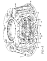
- the mold assembly 10 is typically housed in an optional container housing 49 as shown in Figure 3 .
- the container 49 typically includes a bottom container plate 50 having a plurality of optional wear pads 52 thereon.
- the wear plate 50 has an inner annulus 54 for supporting the sidewall plate 22 and bead ring 42 thereon as shown in Figure 3 .
- the segments 12 are shown positioned about the sidewall plate 22. Surrounding the segments 12 are a plurality of slide blocks 60.
- the slide blocks 60 have flanged ends 62, 64 for receiving and supporting the segments 12 therein.
- the slide blocks 60 have a top and a bottom surface 65 for contacting the container plates 50 and wear plates 52.
- the slide blocks 60 are slidable in a radial direction.
- the container housing further comprises an annular actuating ring 70.
- the inner radial surface 72 of the actuating ring 70 is angled for engagement with an outer angled surface 74 of slide blocks 60. As the actuating ring 70 is lowered, the inner radial surface 72 of the actuating ring engages the outer surface 74 of slide blocks, causing the slide blocks to slide radially inward. The camming action of the actuator ring 70 moves the slide blocks 60 radially inward. As the slide blocks move radially inward, the radially inner surface 76 of the slide block engages the outer radial surface 78 of the adjacent segment, moving the segment radially inward as the actuating ring is lowered into position.
- Figure 2 illustrates a rear view of two of the tread mold segments.
- the tread mold segments 12 have an outer radial surface 78 having a first or upper portion 80 and a second or lower portion 82.
- the first and second portions 80, 82 further comprise an open channel 84, 86 for receiving a tubular member 88, 90 respectively, therein.
- the tubular member 88, 90 may be flexible. As shown in Figure 2 , the tubular member is oriented for example, along the circumferential direction although other orientations may be utilized. It is preferred that the channel be deep enough so that the tubular member 88, 90 is flush or recessed when mounted in the channel.
- the open channels 84, 86 may be located in other locations such as the top and bottom surfaces of the tread segments or other location as desired.
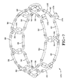
- Figure 7 illustrates the complete manifold assembly 100, wherein the mold has been removed for clarity.
- the manifold assembly 100 comprises one or more inlet ports 102 and one or more outlet ports 104. Fluid such as steam enters the inlet port 102 and is routed through tubular members 88, 90.
- Tubular members 88, 90 are received in channels 84, 86 of a segment 12 and function to heat the segments by conduction of heat from the fluid flowing in the tubular segments 88, 90.
- a cross member 92 connects tubular member 88 on a first segment 12 to a lower tubular member 90 on an adjacent segment 12'.
- a second cross member 94 connects tubular member 88 to lower tubular member 90 on an adjacent segment.
- the cross members 92, 94 cross over each other where the segments are joined.
- the cross members 92, 94 are made of strong, flexible material such as polytetrafluorethylene (PTFE) reinforced with a stainless steel braid. This connection pattern is repeated for each segment.
- PTFE polytetrafluorethylene
- the upper and lower hose is joined together forming an outlet port. Because the segments move radially inward and outward, the hose segments must be flexible to accommodate the movement.
- the upper tubular members 88 form a circle and are not joined together.
- the lower tubular members 90 also form a circle although they are not directly connected together.
- Figure 4 illustrates the assembled mold with the actuating ring removed.
- the slide blocks 60 as shown have a reduced circumferential width so they appear staggered apart, and side faces 96,98 are not in contact with either other when the mold is assembled.
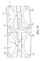
- Figure 8 illustrates the outer radial surface 78 of the segments 12.
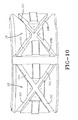
- the outer radial surface of the segments 12 have an X shaped channel 300.
- Received in the X shaped channel is an X shaped coupling 302.
- the X shaped coupling has two ports 304, 106 on one side, and two ports 108, 110 on the other side.
- An X shaped coupling is received in the channel of each segment.
- the couplings are connected together by cross members 112, 114.
- Cross member 112 joins upper coupling port 108 to lower coupling port 106 located on an adjacent coupling.
- Cross member 114 joins upper coupling port 304 to lower coupling port 110 of an adjacent coupling.
- the X shaped couplings on each segment are thus connected together with the cross members forming a manifold to conduct a fluid medium therein.
- the fluid medium may be steam or other fluid as desired.
- the invention is not limited to the X shaped couplings, as other shapes would work for the invention.
- Figure 11 illustrates a sidewall plate assembly 200 suitable for use in any type of conventional mold having a sidewall plate, whether segmented or not.
- the mold sidewall plate of the present invention may be used in any of the molds described above.
- the assembly comprises a mold sidewall plate 210 which includes an outer mold surface 212 for mating with the bead area of a green tire to be cured
- the mold sidewall plate 210 further comprises a channel 220 which has an opening on an inner surface 218 and forming a recess which extends radially outward towards surface 212.
- the channel 220 is preferably annular and is preferably located opposite the bead ring split 214.
- the channel 220 has an inlet 222 and an outlet 224.
- the inlet is located adjacent the outlet but separated by a divider wall 223, so that a heat conducting medium such as steam can traverse almost the entire annular passageway of the sidewall plate 210.
- Figure 12 illustrates one example of the channel configuration. As shown in Figure 11 , the mold sidewall plate 210 cooperates with a lower plate 230 in order to form an enclosed annular passageway 220.
- the lower plate 230 has an upper face 232 having a radial lip 233 for seating the inner surface 218 of the sidewall plate 210 therein.
- the lower plate 230 further comprises inlet and outlet channels 240, 250 which may be oriented in a radial direction.
- the inlet channel 240 has an inlet end 242 for receiving a fluid heat transfer medium such as steam, and an outlet end 244 in fluid communication with the inlet 222 of channel 220.
- a gasket or other sealing means 246 may be provided between the channel inlet 242 and the mold bead inlet.
- the steam or fluid medium exits the ring 210 via outlet 224 and into channel 250 on lower plate.
- the heat transfer medium could also be conveyed to an opening in the inner annulus of the mold bead ring.
- the annular cavity could also be formed completely within the sidewall plate 210, with channel openings on the inner annulus.
- the sidewall plate of the present invention can be used in conventional molds which have a sidewall plate.
- the invention can be utilized in both the upper and lower sidewall plate positions, or just one (for example, the lower) position.
- the invention could also be extended to the mold bead rings.
Landscapes
- Engineering & Computer Science (AREA)
- Mechanical Engineering (AREA)
- Moulds For Moulding Plastics Or The Like (AREA)
- Heating, Cooling, Or Curing Plastics Or The Like In General (AREA)
Abstract
Description
- The present invention relates to a mold for a pneumatic radial tire, and more particularly, to a segmented tire mold.
- Tire molds for molding pneumatic tires are typically constructed of steel or aluminum, and heated by steam platens or by placing the molds in potheaters. Thermal conduction is usually relied upon to transfer the heat from the heat source to the tread and sidewall forming surfaces. It is desirable to maximize the heat conduction to the tread and sidewall forming surfaces. If the thermal conduction is less than optimum, it will require additional cure time and energy costs resulting in reduced production capacity for the mold and higher operating costs. Inefficient thermal conduction can also result in temperature non-uniformity in the mold. The time to cure a tire is limited by the point of least cure on the tire, which is typically located on the undertread. For certain types of tires such as run flat tires, the point of least cure is often located in the bead apex area. Thus if this area could be cured quicker, the entire time of the process may be reduced. Thus an improved mold is desired which can heat the tire more quickly, uniformly and efficiently.
- The invention relates to a mold according to claim 1.
- Dependent claims refer to preferred embodiments of the invention.
- In one aspect, the invention provides a mold comprising an annular cavity to mold a tire, the mold further comprising one or more sidewall plates, wherein at least one of said sidewall plates has an recessed channel having an inlet and an outlet, said sidewall plate having an inner surface in engagement with an annular surface of a container plate, wherein the recessed channel and the annular surface of the container plate form a fluid manifold, for circulating a fluid manifold for circulating a fluid medium.
- In another aspect, the invention provides a mold comprising an annular cavity to mold a tire, the mold further comprising one or more sidewall plates, wherein at least one of said sidewall plates has an recessed channel having an inlet and an outlet, said sidewall plate having an inner surface in engagement with an annular surface of a container plate, wherein the recessed channel and the annular surface of the container plate form a fluid manifold, for circulating a fluid manifold for circulating a fluid medium.
- The invention will be described by way of example and with reference to the accompanying drawings in which:
-
FIG. 1 is a partial cutaway view of a mold assembly showing only the segments, sidewall plates and mold rings; -
FIG. 2 is a rear view of two segments; -
FIG. 3 is a partial cutaway view of a complete tire mold assembly; -
FIG. 4 is a partial cutaway view of the mold assembly ofFIG. 1 , with the actuator ring removed; -
FIG. 5 is a perspective view of the mold shown inFig. 4 , with a portion of the slide blocks removed for clarity; -
FIG. 6 is a perspective view of the entire assembly with the inner parts of the mold shown in phantom; -
FIG. 7 is a perspective view of the flexible steam belt of the invention; -
FIG. 8 is a rear view of a second embodiment of two segments; -
FIG. 9 is a rear view of a coupling assembly and two cross members interconnecting the couplings. -
FIG. 10 is a rear view of two segments showing the channels for insertion of the coupling assembly; -
FIG. 11 is a perspective view of a lower sidewall plate and bottom container plate of the present invention; -
FIG. 12 is a bottom perspective view of the lower sidewall plate ofFIG. 11 ; -
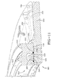
FIG. 13 is a cross-sectional view of the lower sidewall plate and a portion of the bottom container plate; -
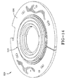
FIG. 14 is a top view of the lower sidewall plate and the bottom container plate; -
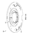
FIG. 15 is a bottom view of the lower sidewall plate and the bottom container plate. - "Axial" and "axially" means the lines or directions that are parallel to the axis of rotation of the tire or tire mold.
- "Circumferential" means lines or directions extending along the perimeter of the surface of the annular tread mold perpendicular to the axial direction.
- "Radial" and "radially" mean directions radially toward or away from the axis of rotation of the tire or tire mold.
- "Sidewall" means a portion of a tire between the tread and the bead.
-
Figure 1 illustrates amold assembly 10. Themold assembly 10 comprises a plurality ofsegments 12 which are arranged to form an annular ring when assembled together. The outer tread surface of a tire is formed by theinner molding surface 14 of thesegments 12, which have a plurality of lands and grooves to mold the tread pattern in a green tire. Themold segments 12 may be radially movable to allow assembly and disassembly of the mold about a green tire. - The
mold assembly 10 further comprises a first andsecond sidewall plate sidewall plate inner mold surface segments 12 to form a smooth continuous surface from the tire tread to the sidewall. Eachsidewall plate outer lip end sidewall plate recess 36, 38 for receiving amold bead area bead ring radiused portion 44, 46 for receiving a bead ring of a green tire thereon. The upper andlower sidewall plate tread segments 12 and the top andbottom bead rings - The
mold assembly 10 is typically housed in anoptional container housing 49 as shown inFigure 3 . Thecontainer 49 typically includes abottom container plate 50 having a plurality ofoptional wear pads 52 thereon. Thewear plate 50 has aninner annulus 54 for supporting thesidewall plate 22 andbead ring 42 thereon as shown inFigure 3 . Thesegments 12 are shown positioned about thesidewall plate 22. Surrounding thesegments 12 are a plurality ofslide blocks 60. Theslide blocks 60 have flangedends segments 12 therein. Theslide blocks 60 have a top and a bottom surface 65 for contacting thecontainer plates 50 and wearplates 52. Theslide blocks 60 are slidable in a radial direction. The container housing further comprises an annular actuatingring 70. The inner radial surface 72 of the actuatingring 70 is angled for engagement with an outerangled surface 74 ofslide blocks 60. As the actuatingring 70 is lowered, the inner radial surface 72 of the actuating ring engages theouter surface 74 of slide blocks, causing the slide blocks to slide radially inward. The camming action of theactuator ring 70 moves theslide blocks 60 radially inward. As the slide blocks move radially inward, the radiallyinner surface 76 of the slide block engages the outerradial surface 78 of the adjacent segment, moving the segment radially inward as the actuating ring is lowered into position. -
Figure 2 illustrates a rear view of two of the tread mold segments. Thetread mold segments 12 have an outerradial surface 78 having a first orupper portion 80 and a second orlower portion 82. The first andsecond portions open channel tubular member tubular member Figure 2 , the tubular member is oriented for example, along the circumferential direction although other orientations may be utilized. It is preferred that the channel be deep enough so that thetubular member open channels -
Figure 7 illustrates thecomplete manifold assembly 100, wherein the mold has been removed for clarity. As shown inFigure 7 , themanifold assembly 100 comprises one ormore inlet ports 102 and one ormore outlet ports 104. Fluid such as steam enters theinlet port 102 and is routed throughtubular members Tubular members channels segment 12 and function to heat the segments by conduction of heat from the fluid flowing in thetubular segments cross member 92 connectstubular member 88 on afirst segment 12 to a lowertubular member 90 on an adjacent segment 12'. Asecond cross member 94 connectstubular member 88 to lowertubular member 90 on an adjacent segment. Thecross members cross members Figure 7 , the uppertubular members 88 form a circle and are not joined together. The lowertubular members 90 also form a circle although they are not directly connected together. -
Figure 4 illustrates the assembled mold with the actuating ring removed. The slide blocks 60 as shown have a reduced circumferential width so they appear staggered apart, and side faces 96,98 are not in contact with either other when the mold is assembled. -
Figure 8 illustrates the outerradial surface 78 of thesegments 12. As shown inFigure 10 , the outer radial surface of thesegments 12 have an X shaped channel 300. Received in the X shaped channel is an X shaped coupling 302. The X shaped coupling has twoports 304, 106 on one side, and twoports cross members Cross member 112 joinsupper coupling port 108 tolower coupling port 106 located on an adjacent coupling.Cross member 114 joins upper coupling port 304 tolower coupling port 110 of an adjacent coupling. The X shaped couplings on each segment are thus connected together with the cross members forming a manifold to conduct a fluid medium therein. The fluid medium may be steam or other fluid as desired. The invention is not limited to the X shaped couplings, as other shapes would work for the invention. - An embodiment of a mold according to the present invention is shown in
Figures 11 -15 .Figure 11 illustrates asidewall plate assembly 200 suitable for use in any type of conventional mold having a sidewall plate, whether segmented or not. The mold sidewall plate of the present invention may be used in any of the molds described above. The assembly comprises amold sidewall plate 210 which includes anouter mold surface 212 for mating with the bead area of a green tire to be cured Themold sidewall plate 210 further comprises achannel 220 which has an opening on aninner surface 218 and forming a recess which extends radially outward towardssurface 212. Thechannel 220 is preferably annular and is preferably located opposite the bead ring split 214. However, the channel may have other shapes and locations. Thechannel 220 has aninlet 222 and anoutlet 224. Preferably the inlet is located adjacent the outlet but separated by adivider wall 223, so that a heat conducting medium such as steam can traverse almost the entire annular passageway of thesidewall plate 210.Figure 12 illustrates one example of the channel configuration. As shown inFigure 11 , themold sidewall plate 210 cooperates with alower plate 230 in order to form an enclosedannular passageway 220. Thelower plate 230 has anupper face 232 having aradial lip 233 for seating theinner surface 218 of thesidewall plate 210 therein. - The
lower plate 230 further comprises inlet andoutlet channels inlet channel 240 has aninlet end 242 for receiving a fluid heat transfer medium such as steam, and anoutlet end 244 in fluid communication with theinlet 222 ofchannel 220. A gasket or other sealing means 246 may be provided between thechannel inlet 242 and the mold bead inlet. Thus the upper face of the lower plate together with thechannel 220 form an annular shaped cavity for conducting a heat transfer medium such as steam, therein. The steam or medium is conveyed to the cavity via the lowerplate inlet channel 240. The heat conducting medium circulates around the sidewall plate in theannular channel 220. The steam or fluid medium exits thering 210 viaoutlet 224 and intochannel 250 on lower plate. Alternatively, the heat transfer medium could also be conveyed to an opening in the inner annulus of the mold bead ring. The annular cavity could also be formed completely within thesidewall plate 210, with channel openings on the inner annulus. - The sidewall plate of the present invention can be used in conventional molds which have a sidewall plate. The invention can be utilized in both the upper and lower sidewall plate positions, or just one (for example, the lower) position. The invention could also be extended to the mold bead rings.
Claims (14)
- A mold comprising an inner face (14) for molding a tire tread, the mold (10) comprising one or more sidewall plates (210), wherein(i) at least one of said sidewall plates (210) comprises an interior channel (220) having an inlet and an outlet (222, 224), said interior channel (220) forming a fluid manifold for circulating a fluid medium within the at least one sidewall plate (210); and/or(ii) at least one of said sidewall plates (210) comprises a recessed channel (220) having an inlet and an outlet (222, 224), said at least one sidewall plate (210) having an inner surface (218) in engagement with a surface of a further plate (230), wherein the recessed channel (220) and the surface of the further plate (230) form a fluid manifold for circulating a fluid medium in said recessed channel (220).
- The mold of claim 1 wherein the mold comprises two sidewall plates (210) on opposite sides of the mold (10), wherein(i) both sidewall plates (210) comprise an interior channel (220) having an inlet and an outlet (222, 224), said interior channel (220) forming a fluid manifold for circulating a fluid medium within the respective sidewall plate (210); or(ii) wherein both sidewall plates (210) comprise a respective recessed channel (220) having an inlet and an outlet (222, 224), said two sidewall plates (210) each having an inner surface (218) in engagement with a surface of a respective further plate (230), wherein the respective recessed channel (220) and the surface of the respective further plate (230) form a fluid manifold for circulating a fluid medium in the respective recessed channel (220); or(iii) wherein one of said two sidewall plates (210) comprises an interior channel (220) having an inlet and an outlet (222, 224), said interior channel (220) forming fluid manifold for circulating a fluid medium within this sidewall plate (210), and wherein the other one of said two sidewall plates (210) comprises a recessed channel (220) having an inlet and an outlet (222, 224), said sidewall plate (210) having an inner surface (218) in engagement with a surface of a further plate (230), wherein the recessed channel (220) and the surface of the further plate (230) form a fluid manifold for circulating a fluid medium in said recessed channel (220).
- The mold of at least one of the previous claims wherein the at least one sidewall plate (210) comprises a projection or bead ring split (214), and wherein the interior channel (220) and/or the recessed channel is located opposite the projection or bead ring split (214).
- The mold of at least one of the previous claims wherein the further plate is a mold container plate (230).
- The mold of at least one of the previous claims wherein the recessed channel (220) and the surface of the further plate (230) form an enclosed annular fluid passageway.
- The mold of at least one of the previous claims wherein the further plate (230) has a radial lip (233) for seating an inner surface (218) of the sidewall plate (210) therein.
- The mold of at least one of the previous claims wherein a sealing means (246) is provided between the sidewall plate (210) and the further plate (230).
- The mold of at least one of the previous claims wherein the at least one sidewall plate comprises a sidewall plate element and a bead ring element (214) attached to the sidewall plate element, and wherein(i) the sidewall plate element comprises an interior channel having an inlet and an outlet, said interior channel forming a fluid manifold for circulating a fluid medium within the sidewall plate element; and/or(ii) the bead ring element and/or the sidewall plate element comprises a recessed channel having an inlet and an outlet, the sidewall plate element having a surface in engagement with a surface of the bead ring element, the recessed channel forming a fluid manifold for circulating a fluid medium.
- The mold of at least one of the previous claims wherein the interior channel (220) and/or the recessed channel (220) is annular.
- The mold of at least one of the previous claims wherein the interior channel (220) and/or the recessed channel (220) channel is at least substantially annular and extends circumferentially with regard to the respective sidewall plate in the range of 320 to 350 degrees.
- The mold of at least one of the previous claims wherein the inlet (222) is connected to an inlet channel (240) and/or the outlet (224) is connected to an outlet channel (250).
- The mold of claim 11 wherein the inlet channel (240) and/or the outlet channel (250) extends within a plate or within the further plate (230).
- The mold of at least one of the previous claims wherein the mold (10) comprises a plurality of segments (12) arranged to form an annular cavity to mold a tire.
- The mold of at least one of the previous claims wherein the mold is configured to circulate steam, water or an other liquid within the fluid manifold.
Applications Claiming Priority (1)
| Application Number | Priority Date | Filing Date | Title |
|---|---|---|---|
| US1538607P | 2007-12-20 | 2007-12-20 |
Publications (2)
| Publication Number | Publication Date |
|---|---|
| EP2072235A1 true EP2072235A1 (en) | 2009-06-24 |
| EP2072235B1 EP2072235B1 (en) | 2014-01-15 |
Family
ID=40380593
Family Applications (1)
| Application Number | Title | Priority Date | Filing Date |
|---|---|---|---|
| EP08171064.2A Ceased EP2072235B1 (en) | 2007-12-20 | 2008-12-09 | Tire mold |
Country Status (3)
| Country | Link |
|---|---|
| US (1) | US20090162460A1 (en) |
| EP (1) | EP2072235B1 (en) |
| BR (1) | BRPI0805536A2 (en) |
Cited By (2)
| Publication number | Priority date | Publication date | Assignee | Title |
|---|---|---|---|---|
| WO2015086580A1 (en) | 2013-12-10 | 2015-06-18 | Compagnie Generale Des Etablissements Michelin | Mould with sectors for a tyre including insulating supporting plates, and associated moulding method |
| EP3414084A4 (en) * | 2016-02-12 | 2019-09-18 | Wd Racing Oy | DEVICE FOR VULCANIZING A VEHICLE TIRE |
Families Citing this family (2)
| Publication number | Priority date | Publication date | Assignee | Title |
|---|---|---|---|---|
| JP6651779B2 (en) * | 2015-10-08 | 2020-02-19 | 住友ゴム工業株式会社 | Tire curing equipment |
| IT202200026979A1 (en) * | 2022-12-28 | 2024-06-28 | Pirelli | “Apparatus for vulcanizing and molding tires and method for preheating circumferential sectors in an apparatus for vulcanizing and molding tires” |
Citations (3)
| Publication number | Priority date | Publication date | Assignee | Title |
|---|---|---|---|---|
| DE1160606B (en) | 1960-08-20 | 1964-01-02 | Continental Gummi Werke Ag | Vulcanizing mold for pneumatic vehicle tires |
| EP1172198A2 (en) | 2000-07-10 | 2002-01-16 | The Goodyear Tire & Rubber Company | Tire mold heat transfer system |
| EP1468814A2 (en) | 2003-04-17 | 2004-10-20 | The Goodyear Tire & Rubber Company | Mould for moulding a tire comprising a locking ring for locking the tread forming segments and method of curing a tire |
Family Cites Families (9)
| Publication number | Priority date | Publication date | Assignee | Title |
|---|---|---|---|---|
| US1644678A (en) * | 1927-10-11 | Assighos | ||
| US2046372A (en) * | 1935-06-12 | 1936-07-07 | Shaler Company | Heat exchanging mold |
| US2185542A (en) * | 1936-08-03 | 1940-01-02 | Royal G Daniel | Vulcanizer adapter |
| US2834984A (en) * | 1955-03-31 | 1958-05-20 | Robbins Tire And Rubber Compan | Vulcanizing apparatus |
| US3154814A (en) * | 1963-04-30 | 1964-11-03 | Super Mold Corp | Tire curing apparatus |
| US3910735A (en) * | 1971-10-15 | 1975-10-07 | Pirelli | Apparatus for molding and curing a pneumatic tire in a perfectly centered position with respect to the equatorial plane of the curing mold |
| US3833323A (en) * | 1973-02-26 | 1974-09-03 | Uniroyal Ag | Segmental mold |
| IT1160163B (en) * | 1983-01-12 | 1987-03-04 | Pirelli | IMPROVEMENTS FOR VULCANIZATION DEVICES FOR TIRES |
| JPH07195370A (en) * | 1993-12-28 | 1995-08-01 | Bridgestone Corp | Tire vulcanizing mold and tire vulcanizing method |
-
2008
- 2008-10-24 US US12/257,434 patent/US20090162460A1/en not_active Abandoned
- 2008-12-09 EP EP08171064.2A patent/EP2072235B1/en not_active Ceased
- 2008-12-16 BR BRPI0805536-0A patent/BRPI0805536A2/en not_active Application Discontinuation
Patent Citations (3)
| Publication number | Priority date | Publication date | Assignee | Title |
|---|---|---|---|---|
| DE1160606B (en) | 1960-08-20 | 1964-01-02 | Continental Gummi Werke Ag | Vulcanizing mold for pneumatic vehicle tires |
| EP1172198A2 (en) | 2000-07-10 | 2002-01-16 | The Goodyear Tire & Rubber Company | Tire mold heat transfer system |
| EP1468814A2 (en) | 2003-04-17 | 2004-10-20 | The Goodyear Tire & Rubber Company | Mould for moulding a tire comprising a locking ring for locking the tread forming segments and method of curing a tire |
Cited By (3)
| Publication number | Priority date | Publication date | Assignee | Title |
|---|---|---|---|---|
| WO2015086580A1 (en) | 2013-12-10 | 2015-06-18 | Compagnie Generale Des Etablissements Michelin | Mould with sectors for a tyre including insulating supporting plates, and associated moulding method |
| US9796149B2 (en) | 2013-12-10 | 2017-10-24 | Compagnie Generale Des Establissements Michelin | Mold with sectors for a tire including insulating supporting plates, and associated molding method |
| EP3414084A4 (en) * | 2016-02-12 | 2019-09-18 | Wd Racing Oy | DEVICE FOR VULCANIZING A VEHICLE TIRE |
Also Published As
| Publication number | Publication date |
|---|---|
| EP2072235B1 (en) | 2014-01-15 |
| US20090162460A1 (en) | 2009-06-25 |
| BRPI0805536A2 (en) | 2009-08-25 |
Similar Documents
| Publication | Publication Date | Title |
|---|---|---|
| EP2072233B1 (en) | Tire mold | |
| EP2072234B1 (en) | Tire mold | |
| EP2072235B1 (en) | Tire mold | |
| EP0893237A2 (en) | Segmented toroidal core for manufacturing pneumatic tires | |
| CN113524645B (en) | Molding device | |
| CN104684717A (en) | Vulcanizing device with radially mobile segments for a tyre | |
| EP0099735B1 (en) | Apparatus for the heat treatment of materials | |
| CA2689955A1 (en) | Tire mold with vent inlet disposed under mold rib | |
| US11020919B2 (en) | Tire vulcanization mold, tire vulcanization device, and tire production method | |
| IT202200026979A1 (en) | “Apparatus for vulcanizing and molding tires and method for preheating circumferential sectors in an apparatus for vulcanizing and molding tires” | |
| US4028168A (en) | Kettle used in the retreading or repair of tires | |
| US7513763B1 (en) | Tire press center mechanism | |
| US6726460B2 (en) | Collapsible mechanism for molding a tire bead | |
| CN105813830A (en) | Segmented mold for tire, and related molding method | |
| CN219727271U (en) | Heating plate for tyre mould | |
| US20250229502A1 (en) | Apparatus for vulcanising a tyre, and method for operating an apparatus for vulcanising tyres | |
| US11318693B2 (en) | Tire vulcanization mold, tire vulcanization device, and tire production method | |
| US1387381A (en) | Tire-vulcanizing method and apparatus | |
| US1655861A (en) | Molding and vulcanizing apparatus | |
| KR101843496B1 (en) | Large diameter long hose making device | |
| US1542801A (en) | Tire mold | |
| WO2016147075A1 (en) | Seal system for melted plastics |
Legal Events
| Date | Code | Title | Description |
|---|---|---|---|
| PUAI | Public reference made under article 153(3) epc to a published international application that has entered the european phase |
Free format text: ORIGINAL CODE: 0009012 |
|
| AK | Designated contracting states |
Kind code of ref document: A1 Designated state(s): AT BE BG CH CY CZ DE DK EE ES FI FR GB GR HR HU IE IS IT LI LT LU LV MC MT NL NO PL PT RO SE SI SK TR |
|
| AX | Request for extension of the european patent |
Extension state: AL BA MK RS |
|
| 17P | Request for examination filed |
Effective date: 20091228 |
|
| 17Q | First examination report despatched |
Effective date: 20100127 |
|
| AKX | Designation fees paid |
Designated state(s): DE FR IT NL |
|
| GRAP | Despatch of communication of intention to grant a patent |
Free format text: ORIGINAL CODE: EPIDOSNIGR1 |
|
| INTG | Intention to grant announced |
Effective date: 20130725 |
|
| GRAS | Grant fee paid |
Free format text: ORIGINAL CODE: EPIDOSNIGR3 |
|
| GRAA | (expected) grant |
Free format text: ORIGINAL CODE: 0009210 |
|
| AK | Designated contracting states |
Kind code of ref document: B1 Designated state(s): DE FR IT NL |
|
| REG | Reference to a national code |
Ref country code: DE Ref legal event code: R096 Ref document number: 602008029912 Country of ref document: DE Effective date: 20140227 |
|
| REG | Reference to a national code |
Ref country code: NL Ref legal event code: T3 |
|
| REG | Reference to a national code |
Ref country code: DE Ref legal event code: R097 Ref document number: 602008029912 Country of ref document: DE |
|
| PLBE | No opposition filed within time limit |
Free format text: ORIGINAL CODE: 0009261 |
|
| STAA | Information on the status of an ep patent application or granted ep patent |
Free format text: STATUS: NO OPPOSITION FILED WITHIN TIME LIMIT |
|
| 26N | No opposition filed |
Effective date: 20141016 |
|
| REG | Reference to a national code |
Ref country code: DE Ref legal event code: R097 Ref document number: 602008029912 Country of ref document: DE Effective date: 20141016 |
|
| REG | Reference to a national code |
Ref country code: FR Ref legal event code: PLFP Year of fee payment: 8 |
|
| REG | Reference to a national code |
Ref country code: FR Ref legal event code: PLFP Year of fee payment: 9 |
|
| PGFP | Annual fee paid to national office [announced via postgrant information from national office to epo] |
Ref country code: NL Payment date: 20161207 Year of fee payment: 9 |
|
| REG | Reference to a national code |
Ref country code: FR Ref legal event code: PLFP Year of fee payment: 10 |
|
| PGFP | Annual fee paid to national office [announced via postgrant information from national office to epo] |
Ref country code: FR Payment date: 20171120 Year of fee payment: 10 |
|
| PGFP | Annual fee paid to national office [announced via postgrant information from national office to epo] |
Ref country code: DE Payment date: 20171221 Year of fee payment: 10 |
|
| REG | Reference to a national code |
Ref country code: NL Ref legal event code: MM Effective date: 20180101 |
|
| PG25 | Lapsed in a contracting state [announced via postgrant information from national office to epo] |
Ref country code: NL Free format text: LAPSE BECAUSE OF NON-PAYMENT OF DUE FEES Effective date: 20180101 |
|
| REG | Reference to a national code |
Ref country code: DE Ref legal event code: R119 Ref document number: 602008029912 Country of ref document: DE |
|
| PG25 | Lapsed in a contracting state [announced via postgrant information from national office to epo] |
Ref country code: IT Free format text: LAPSE BECAUSE OF NON-PAYMENT OF DUE FEES Effective date: 20181209 Ref country code: FR Free format text: LAPSE BECAUSE OF NON-PAYMENT OF DUE FEES Effective date: 20181231 Ref country code: DE Free format text: LAPSE BECAUSE OF NON-PAYMENT OF DUE FEES Effective date: 20190702 |
|
| PG25 | Lapsed in a contracting state [announced via postgrant information from national office to epo] |
Ref country code: IT Free format text: LAPSE BECAUSE OF NON-PAYMENT OF DUE FEES Effective date: 20181209 |
|
| PGFP | Annual fee paid to national office [announced via postgrant information from national office to epo] |
Ref country code: IT Payment date: 20191231 Year of fee payment: 11 |
|
| PGRI | Patent reinstated in contracting state [announced from national office to epo] |
Ref country code: IT Effective date: 20191128 |
|
| PG25 | Lapsed in a contracting state [announced via postgrant information from national office to epo] |
Ref country code: IT Free format text: LAPSE BECAUSE OF NON-PAYMENT OF DUE FEES Effective date: 20191209 |