EP2071765A1 - A method and network unit device for transferring the test message - Google Patents
A method and network unit device for transferring the test message Download PDFInfo
- Publication number
- EP2071765A1 EP2071765A1 EP07817263A EP07817263A EP2071765A1 EP 2071765 A1 EP2071765 A1 EP 2071765A1 EP 07817263 A EP07817263 A EP 07817263A EP 07817263 A EP07817263 A EP 07817263A EP 2071765 A1 EP2071765 A1 EP 2071765A1
- Authority
- EP
- European Patent Office
- Prior art keywords
- packet
- test message
- ethernet
- interface
- control module
- Prior art date
- Legal status (The legal status is an assumption and is not a legal conclusion. Google has not performed a legal analysis and makes no representation as to the accuracy of the status listed.)
- Granted
Links
Images


Classifications
-
- H—ELECTRICITY
- H04—ELECTRIC COMMUNICATION TECHNIQUE
- H04L—TRANSMISSION OF DIGITAL INFORMATION, e.g. TELEGRAPHIC COMMUNICATION
- H04L61/00—Network arrangements, protocols or services for addressing or naming
- H04L61/35—Network arrangements, protocols or services for addressing or naming involving non-standard use of addresses for implementing network functionalities, e.g. coding subscription information within the address or functional addressing, i.e. assigning an address to a function
-
- H—ELECTRICITY
- H04—ELECTRIC COMMUNICATION TECHNIQUE
- H04L—TRANSMISSION OF DIGITAL INFORMATION, e.g. TELEGRAPHIC COMMUNICATION
- H04L43/00—Arrangements for monitoring or testing data switching networks
- H04L43/50—Testing arrangements
-
- H—ELECTRICITY
- H04—ELECTRIC COMMUNICATION TECHNIQUE
- H04L—TRANSMISSION OF DIGITAL INFORMATION, e.g. TELEGRAPHIC COMMUNICATION
- H04L2101/00—Indexing scheme associated with group H04L61/00
- H04L2101/60—Types of network addresses
- H04L2101/618—Details of network addresses
- H04L2101/622—Layer-2 addresses, e.g. medium access control [MAC] addresses
-
- H—ELECTRICITY
- H04—ELECTRIC COMMUNICATION TECHNIQUE
- H04L—TRANSMISSION OF DIGITAL INFORMATION, e.g. TELEGRAPHIC COMMUNICATION
- H04L41/00—Arrangements for maintenance, administration or management of data switching networks, e.g. of packet switching networks
- H04L41/12—Discovery or management of network topologies
Definitions
- the present invention relates to network communication technologies, and in particular, to a method for transferring test messages in the optical transport network technology field, and to a Network Element (NE) device for sending and receiving test messages.
- NE Network Element
- ASON Automatically Switched Optical Network
- ASON is a new-generation optical transport network which implements the optical network switching connection function automatically in an intelligent way.
- the ASON needs to have basic functions, including automatic resource discovery (for example, neighbor discovery, topology discovery, and service discovery), routing function, and signaling function.
- the existing LMP supports Synchronous Digital Hierarchy (SDH) interfaces.
- SDH Synchronous Digital Hierarchy
- test messages are transferred through the logical channels provided by the overhead bytes in the SDH frame. That is, the LMP entity of the transmitter NE constructs a test message packet.
- the packet includes 16 bytes regularly, and extra bytes are input as 0s.
- the 16-byte test messages are inserted cyclically into the J0 overhead bytes of an SDH frame through a lower-layer driver, and SDH frames are sent.
- the receiver NE extracts J0 overhead bytes according to the 16 received J0 SDH frames, makes the 16 extracted J0 overhead bytes into a 16-byte test message packet, and sends the test message packet to the LMP entity of the receiver NE through the lower-layer driver.
- the solution under the prior art only deals with transferring the test messages through an SDH interface so that the LMP can support auto discovery of SDH links of the data plane.
- the control plane of the Transport MPLS Multiprotocol Label Switching (TMPLS)/Provider Backbone Transport (PBT) network uses the GMPLS
- the data plane of the TMPLS/PBT transport network uses the Ethernet data interface widely.
- No solution is currently available to support auto discovery of the Ethernet physical links. That is, the technical solution to transferring test messages on the Ethernet data interface is pending.
- Various embodiments of the present invention are to provide a method for transferring test messages, and an NE device for sending and receiving test messages.
- a method for transferring test messages is provided in an embodiment of the present invention, where the first NE is connected with the second NE through an Ethernet physical link.
- the method includes:
- Another method for transferring test messages is provided in an embodiment of the present invention, where the first NE is connected with the second NE through an Ethernet physical link.
- the method includes:
- Another method for transferring test messages is provided in an embodiment of the present invention, where the first NE is connected with the second NE through an Ethernet physical link.
- the method includes:
- Another method for transferring test messages is provided in an embodiment of the present invention, where the first NE is connected with the second NE through an Ethernet physical link.
- the method includes:
- the LMP entity supports the negotiation mechanism, and may select the type of the logical channel, for example, logical channel of the protocol stack mode, logical channel of the VLAN mode, and logical channel of the special MAC address mode; the packet control module of the NE device encapsulates the test message packet according to the logical channel type determined through negotiation. Therefore, the test message can be transferred on the Ethernet data interface, and the auto discovery of the Ethernet physical link of the NE device succeeds once the test message is transferred successfully.
- the foregoing types of logical channels may be negotiated according to the actual application conditions, and the available logical channel may be selected flexibly so that the test message may be transferred between the NE devices more conveniently.
- Figure 1 is a flowchart of a method for transferring test messages in the first embodiment of the present invention
- Figure 2 is another flowchart of a method for transferring test messages in the second embodiment of the present invention.
- Figure 3 is another flowchart of a method for transferring test messages in the third embodiment of the present invention.
- Figure 4 is another flowchart of a method for transferring test messages in the fourth embodiment of the present invention.
- Figure 5 shows an NE device in the fifth embodiment of the present invention.
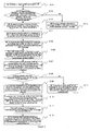
- FIG. 1 is a flowchart of a method for transferring test messages in the first embodiment of the present invention.
- NE A sends a Begin Verify message to NE B through the control channel.
- the message carries the TE link ID of NE A and the first parameter information, where the first parameter information includes the NE A logical channel type which supports transfer of test messages, and the frequency of sending test messages.
- NE B receives the BeginVerify message, obtains the TE link ID of NE A and the first parameter information, and judges whether the NE B itself has the logical channel type identical to the NE A logical channel type which supports transfer of test messages. If such is the case, the process proceeds with step S103; otherwise, the process proceeds with S113, where the NE B sends a BeginVerifyNAck message carrying error information to NE A through the control channel. At this time, the auto discovery of the Ethernet physical link fails.
- NE B selects one of the logical channel types, and allocates a verification ID (hereinafter referred to as "Verify_ID”), correlates the Verify_ID with the TE link ID of NE A, and saves the correlation information and the logical channel type information.
- Verify_ID a verification ID
- NE B sends a BeginVerifyAck message to NE A through the control channel.
- the message carries the Verify_ID and the second parameter information, where the second parameter information includes the logical channel type which is selected by the NE B and supports transfer of test messages, and the time range set for NE B to receive test messages.
- NE A After receiving the BeginVerifyAck message, NE A saves the Verify_ID and the second parameter information carried in the message, and starts sending the test message.
- S106 The LMP entity of NE .
- A constructs a test message packet which includes the Verify_ID allocated by NE B and the local Ethernet data interface ID, and transfers the test message packet to the local packet control module.
- the NE A packet control module encapsulates the test message packet according to the different logical channel type selected through negotiation between NE A and NE B, and transfers the encapsulated packet which carries the test message packet to the transmitting interface corresponding to the local Ethernet data interface ID, and the Ethernet physical link connected with the transmitting interface transfers the packet.
- step S108 A judgment is made about whether the test message packet is received in the specified time. If such is the case, the process proceeds with step S109; otherwise, the process proceeds with step S114, where NE B sends a TestStatusFailure message to NE A through the control channel. At this time, the NE A and NE B fail to discover the Ethernet physical link automatically.
- the receiving interface of NE B connected with the Ethernet physical link identifies that the packet carries the test message packet, and receives the packet.
- the NE B packet control module obtains the packet from the receiving interface of NE B, and decapsulates the packet.
- the packet control module of NE B transfers the test message packet obtained after decapsulation to the local LMP entity.
- the local LMP entity obtains the corresponding local TE link ID and the local Ethernet data interface ID according to the receiving interface which receives the packet, extracts the Verify_ID and the NE A Ethernet data interface ID from the test message packet obtained after decapsulation, correlates the local TE link ID with the TE link ID of NE A according to the stored information about correlation between the Verify_ID and the TE link ID of NE A, correlates the local Ethernet data interface ID with the Ethernet data interface ID of NE A, and stores the correlation information.
- NE B has obtained the information about the local NE and NE A based on the Ethernet physical link.
- S111 The LMP entity of NE B sends a TestStatusSuccess message to NE A through the control channel, where the message carries the Verify_ID, TE link ID of NE B, Ethernet data interface ID of NE B, and Ethernet data interface ID of NE A.
- NE A After receiving the TestStatusSuccess message, NE A obtains the correlated local TE link ID, local Ethernet data interface ID, TE link ID of NE B, and Ethernet data interface ID of NE B based on the Ethernet physical link, and then sends a TestStatusAck message to NE B through the control channel.
- this embodiment newly defines the BEGIN_VERIFY object in the parameter information carried in the negotiation message.
- the value of the "EncType” field of the object is the Ethernet type, and the "Verify Transport Mechanism” field of the object defines four bit values.
- the BEGIN_VERIFY object is detailed below:
- the types of logical channels include: protocol stack mode, VLAN mode, and special MAC address mode.
- Each different logical channel type decides a different encapsulation format and transfer mode of the test message packet.
- the technical solution in embodiment 1 elaborates the method for transferring test messages on the Ethernet data interface after selecting a different type of logical channel through negotiation.
- the auto discovery of the Ethernet physical link of the NE device succeeds once the test message is transferred successfully.
- the method of the LMP entity transferring test messages on the Ethernet data interface is detailed below, taking the logical channel of the protocol stack mode, VLAN mode, and special MAC address mode as examples.
- the protocol stack mode is subdivided into User Datagram Protocol (UDP) mode and Transmission Control Protocol (TCP) mode.
- the protocol stack mode needs support of the Internet Protocol (IP) protocol stack, uses the IP protocol stack to encapsulate the corresponding packet, and uses the IP protocol stack to create a Point-to-Point Protocol (PPP) interface corresponding to each Ethernet data interface in order to implement transfer of test message packets to the PPP interface.
- IP Internet Protocol
- PPP Point-to-Point Protocol
- the optical/electrical interface IDs correspond to and are mutually convertible to the Ethernet data interface IDs; and (2) the optical/electrical interface IDs correspond to and are mutually convertible to the PPP interface IDs.
- Figure 2 is a flowchart of another method for transferring test messages in the second embodiment of the present invention.
- NE A and NE B negotiate to provide a logical channel in the UDP mode, and store the information about the logical channel type.
- the LMP entity of NE A constructs a test message packet which includes the Verify_ID allocated by NE B and the Ethernet data interface ID, and transfers the test message packet to the local packet control module.
- the NE A packet control module encapsulates the test message packet into a UDP packet which carries the test message packet by using the IP protocol stack function according to the logical channel type of the UDP mode determined through negotiation, transfers the UDP packet to the PPP interface corresponding to the local Ethernet data interface ID, and transfers the UDP packet through the Ethernet physical link connected with the PPP interface.
- the foregoing text describes the encapsulation and transfer processes from the perspective of lower-layer protocol stack operation.
- NE A and NE B need to create a socket descriptor beforehand.
- the socket descriptor is correlated with the multicast IP address 224.0.0.1.
- the optical/electrical interface IDs correspond to the Ethernet data interface IDs, and also correspond to the PPP interface IDs. Therefore, the optical/electrical interface ID may be obtained according to the corresponding Ethernet data interface ID, and then the PPP interface ID may be obtained according to the optical/electrical interface ID.
- the PPP interface of NE B connected with the Ethernet physical link identifies that the UDP packet carries the test message packet, and receives the UDP packet.
- the NE B packet control module obtains the protocol stack packet from the PPP interface of NE B by using the IP protocol stack function, and then decapsulates the protocol stack packet.
- the packet control module of NE B transfers the test message packet obtained after decapsulation to the local LMP entity.
- the local LMP entity obtains the corresponding local TE link ID and the local Ethernet data interface ID according to the PPP interface that receives the UDP packet, extracts the Verify_ID and the NE A Ethernet data interface ID from the test message packet obtained after decapsulation, correlates the local TE link ID with the TE link ID of NE A according to the stored information about correlation between the Verify_ID and the TE link ID of NE A, correlates the local Ethernet data interface with the Ethernet data interface of NE A, and stores the correlation information. At this time, the test message is transferred successfully.
- the optical/electrical interface IDs correspond to the Ethernet data interface IDs, and also correspond to the PPP interface IDs. Therefore, the optical/electrical interface ID may be obtained according to the corresponding PPP interface, and then the Ethernet data interface ID may be obtained according to the optical/electrical interface ID.
- the logical channel of the test message is provided in the VLAN mode.
- the corresponding VLAN tag is affixed.
- the corresponding test message packet is identified according to the VLAN tag.
- the value of the VLAN tag is selected by the NE which receives the BeginVerify message through negotiation.
- a second subcategory of a new ninth category is defined by extending the BEGIN_VERIFY_ACK object, and the VLAN tag carried in the object is defined.
- the types of VLAN tags include the C-VLAN tag used by the customers, and the S-VLAN tag used by the operators.
- the format of the test message packet that carries the VLAN is not limited to the formats described in the third embodiment of the present invention.
- the BEGIN_VERIFY_ACK object is further described below:
- 0x8810 C-VLAN tag used by the customer
- 0x88a8 S-VLAN tag used by the operator
- VLAN tag VLAN tag used for transferring test message packets.
- VLAN mode for negotiation depends on support of the Verify Transport Response. If the Verify Transport Response indicates that the VLAN mode is supported, the packet control modules of the sender NE and receiver NE use the VLAN tag which identifies the test message packet. That is, the NE which initiates negotiation (namely, the NE which sends the Begin Verify message) uses the VLAN tag to send the test message packet; the NE which responds to the negotiation (namely, the NE which sends the Begin Verify Ack message) uses the VLAN tag to receive the test message packet. If the Verify Transport Response indicates that the VLAN mode is not supported, the value of the VLAN tag is set to 0.
- Figure 3 is a flowchart of another method for transferring test messages in the third embodiment of the present invention.
- NE A and NE B negotiate to provide a logical channel in the VLAN mode, and store the information about the logical channel type.
- the LMP entity of NE A constructs a test message packet which includes the Verify_ID allocated by NE B and the Ethernet data interface ID, and transfers the test message packet to the local packet control module.
- the NE A packet control module encapsulates the test message packet into an Ethernet MAC frame which carries a VLAN tag and the test message packet according to the logical channel type of the VLAN mode determined through negotiation, invokes a data plane to transfer the Ethernet MAC frame to an optical/electrical interface corresponding to the local Ethernet data interface, and transfers the Ethernet MAC frame through the Ethernet physical link connected with the optical/electrical interface.
- the destination MAC address of the packet is freely configurable, and the source MAC address may be set to any MAC address of the local NE.
- an optical/electrical interface ID may be obtained according to the Ethernet data interface ID.
- the NE B optical/electrical interface connected with the Ethernet physical link identifies the Ethernet MAC frame according to the VLAN tag, and therefore, determines that the Ethernet MAC frame carries the test message packet. Afterwards, the NE B optical/electrical interface receives the Ethernet MAC frame. The NE B packet control module invokes a data plane to obtain the Ethernet MAC frame from the NE B optical/electrical interface, and decapsulates the Ethernet MAC frame.
- the packet control module of NE B transfers the test message packet obtained after decapsulation to the local LMP entity.
- the local LMP entity obtains the corresponding local TE link ID and the local Ethernet data interface ID according to the optical/electrical interface that receives the Ethernet MAC frame, extracts the Verify_ID and the NE A Ethernet data interface ID from the test message packet obtained after decapsulation, correlates the local TE link ID with the TE link ID of NE A according to the stored information about correlation between the Verify_ID and the TE link ID of NE A, correlates the local Ethernet data interface with the Ethernet data interface of NE A, and stores the correlation information. At this time, the test message is transferred successfully.
- the logical channel for transferring test messages is provided through a preconfigured special MAC address.
- the special MAC address is used as a destination MAC address.
- the test message packet is identified according to the special MAC address.
- the special MAC address is user-definable, for example, set to 01-80-C2-00-11-11; or may be an existing special MAC address, for example, an MAC address defined by the 802.3ah; or may be an MAC address defined by the Link Layer Discovery Protocol (LLDP).
- LLDP Link Layer Discovery Protocol
- Figure 4 is a flowchart of another method for transferring test messages in the fourth embodiment of the present invention.
- NE A and NE B negotiate to provide a logical channel in the special MAC address mode, and store the information about the logical channel type.
- the LMP entity of NE A constructs a test message packet which includes the Verify_ID allocated by NE B and the Ethernet data interface ID, and transfers the test message packet to the local packet control module.
- the NE A packet control module encapsulates the test message packet into an Ethernet MAC frame which uses a special multicast MAC address as a destination MAC address and carries the test message packet according to the logical channel type of the special MAC address mode determined through negotiation, invokes a data plane to transfer the Ethernet MAC frame to an optical/electrical interface corresponding to the local Ethernet data interface, and transfers the Ethernet MAC frame through the Ethernet physical link connected with the optical/electrical interface.
- the NE B optical/electrical interface connected with the Ethernet physical link identifies the Ethernet MAC frame according to the special multicast MAC address, and therefore, determines that the Ethernet MAC frame carries the test message packet. Afterwards, the NE B optical/electrical interface receives the Ethernet MAC frame. The NE B packet control module invokes a data plane to obtain the Ethernet MAC frame from the NE B optical/electrical interface, and decapsulates the Ethernet MAC frame.
- the packet control module of NE B transfers the test message packet obtained after decapsulation to the local LMP entity.
- the local LMP entity obtains the corresponding local TE link ID and the local Ethernet data interface ID according to the optical/electrical interface that receives the Ethernet MAC frame, extracts the Verify_ID and the NE A Ethernet data interface ID from the test message packet obtained after decapsulation, correlates the local TE link ID with the TE link ID of NE A according to the stored information about correlation between the Verify_ID and the TE link ID of NE A, correlates the local Ethernet data interface with the Ethernet data interface of NE A, and stores the correlation information. At this time, the test message is transferred successfully.
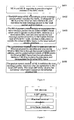
- FIG. 5 shows an NE device in the fifth embodiment of the present invention.
- the NE device includes:
- the logical channel types include protocol stack mode, VLAN mode, and special MAC address mode.
- the LMP entity supports the negotiation mechanism, and may select the type of the logical channel, for example, logical channel of the protocol stack mode, logical channel of the VLAN mode, and logical channel of the special MAC address mode; the packet control module of the NE device encapsulates the test message packet according to the logical channel type determined through negotiation. Therefore, the test message can be transferred on the Ethernet data interface, and the NE device is capable of discovering Ethernet links automatically.
- the foregoing types of logical channels may be negotiated according to the actual application conditions, and the available logical channel may be selected flexibly so that the test message may be transferred between the NE devices more conveniently.
- the second embodiment is characterized by fast and simple implementation, but requires support of the IP protocol stack, and is not applicable if the IP protocol stack is unaware of the Ethernet data interface;
- the third and fourth embodiments of the present invention are characterized by independence of the IP protocol stack, but the third embodiment needs to occupy the VLAN tag, which reduces the available VLAN tags.
Abstract
Description
- This application claims a priority from the Chinese patent application No.
200710072903.0 - The present invention relates to network communication technologies, and in particular, to a method for transferring test messages in the optical transport network technology field, and to a Network Element (NE) device for sending and receiving test messages.
- Automatically Switched Optical Network (ASON) is a new-generation optical transport network which implements the optical network switching connection function automatically in an intelligent way. In order to implement the automatic switching connection function, the ASON needs to have basic functions, including automatic resource discovery (for example, neighbor discovery, topology discovery, and service discovery), routing function, and signaling function.
- In the ASON, when the optical network switching connection is configured through the Generalized Multi-Protocol Label Switching (GMPLS) signaling mechanism, the following circumstances occur:
- In the case that the core network adopts the full optical switching equipment massively, precise fault locating is difficult if no automatic optical/non-optical monitoring capability is available. When the number of fiber links between adjacent NEs increases, the routing protocol is unable to perform link attribute notification for so numerous data links. For the numerous fiber links, the adjacent NEs are unable to identify the links correctly in the case of non-manual configuration; and the management on local links is inconsistent with the management on remote links. The foregoing contents are about ASON resource management. Therefore, the standardization organization has formulated a Link Management Protocol (LMP) for link resource management.
- The existing LMP supports Synchronous Digital Hierarchy (SDH) interfaces. For SDH interfaces, test messages are transferred through the logical channels provided by the overhead bytes in the SDH frame. That is, the LMP entity of the transmitter NE constructs a test message packet. The packet includes 16 bytes regularly, and extra bytes are input as 0s. The 16-byte test messages are inserted cyclically into the J0 overhead bytes of an SDH frame through a lower-layer driver, and SDH frames are sent. The receiver NE extracts J0 overhead bytes according to the 16 received J0 SDH frames, makes the 16 extracted J0 overhead bytes into a 16-byte test message packet, and sends the test message packet to the LMP entity of the receiver NE through the lower-layer driver.
- The solution under the prior art only deals with transferring the test messages through an SDH interface so that the LMP can support auto discovery of SDH links of the data plane. However, because the control plane of the Transport MPLS Multiprotocol Label Switching (TMPLS)/Provider Backbone Transport (PBT) network uses the GMPLS, the data plane of the TMPLS/PBT transport network uses the Ethernet data interface widely. No solution is currently available to support auto discovery of the Ethernet physical links. That is, the technical solution to transferring test messages on the Ethernet data interface is pending.
- Various embodiments of the present invention are to provide a method for transferring test messages, and an NE device for sending and receiving test messages.
- In view of the above, the technical solution under the present invention is implemented in following way.
- A method for transferring test messages is provided in an embodiment of the present invention, where the first NE is connected with the second NE through an Ethernet physical link. The method includes:
- negotiating and selecting, by the first NE and the second NE, a logical channel type;
- constructing, by an LMP entity of the first NE, a test message packet which includes an Ethernet data interface ID of the first NE, and transferring the test message packet to the packet control module of the first NE;
- encapsulating, by the packet control module of the first NE, the test message packet according to the logical channel type determined through negotiation, and transferring the encapsulated packet which carries the test message packet to the transmitting interface corresponding to the Ethernet data interface ID of the first NE;
- identifying and receiving, by the receiving interface of the second NE connected with the Ethernet physical link, the packet;
- obtaining, by the packet control module of the second NE, the packet from the receiving interface of the second NE, and decapsulating the packet; and
- transferring, by the packet control module of the second NE, the test message packet obtained after decapsulation to the LMP entity of the second NE.
- Another method for transferring test messages is provided in an embodiment of the present invention, where the first NE is connected with the second NE through an Ethernet physical link. When the first NE negotiates with the second NE to provide a logical channel in the protocol stack mode, the method includes:
- constructing, by the LMP entity of the first NE, a test message packet which includes an Ethernet data interface ID of the first NE, and transferring the test message packet to the packet control module of the first NE;
- encapsulating, by the packet control module of the first NE, the test message packet into a protocol stack packet which carries the test message packet by using the IP protocol stack function according to the logical channel type of the protocol stack mode, and transferring the protocol stack packet to the PPP interface corresponding to the Ethernet data interface ID of the first NE;
- identifying and receiving, by the PPP interface of the second NE connected with the Ethernet physical link, the protocol stack packet;
- obtaining, by the packet control module of the second NE, the protocol stack packet from the PPP interface of the second NE by using the IP protocol stack function, and decapsulating the packet; and
- transferring, by the packet control module of the second NE, the test message packet obtained after decapsulation to the LMP entity of the second NE.
- Another method for transferring test messages is provided in an embodiment of the present invention, where the first NE is connected with the second NE through an Ethernet physical link. When the first NE negotiates with the second NE to provide a logical channel in the VLAN mode, the method includes:
- constructing, by the LMP entity of the first NE, a test message packet which includes an Ethernet data interface ID of the first NE, and transferring the test message packet to the packet control module of the first NE;
- encapsulating, by the packet control module of the first NE, the test message packet into an Ethernet MAC frame which carries a VLAN tag and the test message packet according to the logical channel type of the VLAN mode, and invoking a data plane to transfer the Ethernet MAC frame to an optical/electrical interface corresponding to the Ethernet data interface ID of the first NE;
- identifying and receiving, by the optical/electrical interface of the second NE connected with the Ethernet physical link, the Ethernet MAC frame through the VLAN tag;
- obtaining, by the packet control module of the second NE, the Ethernet MAC frame from the optical/electrical interface of the second NE by invoking the data plane, and decapsulating the frame; and
- transferring, by the packet control module of the second NE, the test message packet obtained after decapsulation to the LMP entity of the second NE.
- Another method for transferring test messages is provided in an embodiment of the present invention, where the first NE is connected with the second NE through an Ethernet physical link. When the first NE negotiates with the second NE to provide a logical channel in the special MAC address mode, the method includes:
- constructing, by the LMP entity of the first NE, a test message packet which includes an Ethernet data interface ID of the first NE, and transferring the test message packet to the packet control module of the first NE;
- encapsulating, by the packet control module of the first NE, the test message packet into an Ethernet MAC frame which uses a special multicast MAC address as a destination MAC address and carries the test message packet according to the logical channel type of the special MAC address mode, and invoking a data plane to transfer the Ethernet MAC frame to an optical/electrical interface corresponding to the Ethernet data interface ID of the first NE;
- identifying and receiving, by the optical/electrical interface of the second NE connected with the Ethernet physical link, the Ethernet MAC frame through the special multicast MAC address;
- obtaining, by the packet control module of the second NE, the Ethernet MAC frame from the optical/electrical interface of the second NE by invoking the data plane, and decapsulating the frame; and
- transferring, by the packet control module of the second NE, the test message packet obtained after decapsulation to the LMP entity of the second NE.
- An NE device provided in an embodiment of the present invention includes:
- an LMP entity, adapted to: negotiate and select a logical channel type; construct a test message packet which carries a local Ethernet data interface ID, and send the test message packet to the packet control module; and receive the test message packet obtained after decapsulation from the packet control module;
- a packet control module, adapted to: receive the test message packet from the LMP entity, encapsulate the test message packet according to the logical channel type determined through negotiation, and send the encapsulated packet which carries the test message packet to the interface module corresponding to the local Ethernet data interface ID; obtain the packet from the interface module, and decapsulate the packet to obtain the test message packet; and
- an interface module, adapted to: receive the packet from the packet control module, and send the packet to the outside; and identify and receive the packet from the outside.
- Therefore, the technical solution under the prior art transfers the test message only through an SDH interface. In the embodiments of the present invention, the LMP entity supports the negotiation mechanism, and may select the type of the logical channel, for example, logical channel of the protocol stack mode, logical channel of the VLAN mode, and logical channel of the special MAC address mode; the packet control module of the NE device encapsulates the test message packet according to the logical channel type determined through negotiation. Therefore, the test message can be transferred on the Ethernet data interface, and the auto discovery of the Ethernet physical link of the NE device succeeds once the test message is transferred successfully. Moreover, the foregoing types of logical channels may be negotiated according to the actual application conditions, and the available logical channel may be selected flexibly so that the test message may be transferred between the NE devices more conveniently.
- The accompanying drawings are intended for better understanding of the present invention and constitute part of this application rather than limitation to the present invention.
-
Figure 1 is a flowchart of a method for transferring test messages in the first embodiment of the present invention; -
Figure 2 is another flowchart of a method for transferring test messages in the second embodiment of the present invention; -
Figure 3 is another flowchart of a method for transferring test messages in the third embodiment of the present invention; -
Figure 4 is another flowchart of a method for transferring test messages in the fourth embodiment of the present invention; and -
Figure 5 shows an NE device in the fifth embodiment of the present invention. - In order to make the present invention clearer to those skilled in the art, the embodiments of present invention are described below by reference to accompanying drawings. The exemplary embodiments of the present invention and description thereof are intended for interpreting rather than limiting the present invention.
- The method for transferring test messages on the Ethernet data interface of the point-to-point physical link connection is detailed in embodiment 1. It is worthy of attention that for a TMPLS/PBT transport network, the Ethernet data interface is generally of the unnumbered interface type, namely, the interface type without IP address. Besides, the method provided in this embodiment is also applicable to the numbered interface type.
Figure 1 is a flowchart of a method for transferring test messages in the first embodiment of the present invention. - S101: NE A sends a Begin Verify message to NE B through the control channel. The message carries the TE link ID of NE A and the first parameter information, where the first parameter information includes the NE A logical channel type which supports transfer of test messages, and the frequency of sending test messages.
- S102: NE B receives the BeginVerify message, obtains the TE link ID of NE A and the first parameter information, and judges whether the NE B itself has the logical channel type identical to the NE A logical channel type which supports transfer of test messages. If such is the case, the process proceeds with step S103; otherwise, the process proceeds with S113, where the NE B sends a BeginVerifyNAck message carrying error information to NE A through the control channel. At this time, the auto discovery of the Ethernet physical link fails.
- S103: NE B selects one of the logical channel types, and allocates a verification ID (hereinafter referred to as "Verify_ID"), correlates the Verify_ID with the TE link ID of NE A, and saves the correlation information and the logical channel type information.
- S104: NE B sends a BeginVerifyAck message to NE A through the control channel. The message carries the Verify_ID and the second parameter information, where the second parameter information includes the logical channel type which is selected by the NE B and supports transfer of test messages, and the time range set for NE B to receive test messages.
- S105: After receiving the BeginVerifyAck message, NE A saves the Verify_ID and the second parameter information carried in the message, and starts sending the test message.
- S106: The LMP entity of NE.A constructs a test message packet which includes the Verify_ID allocated by NE B and the local Ethernet data interface ID, and transfers the test message packet to the local packet control module.
- S107: The NE A packet control module encapsulates the test message packet according to the different logical channel type selected through negotiation between NE A and NE B, and transfers the encapsulated packet which carries the test message packet to the transmitting interface corresponding to the local Ethernet data interface ID, and the Ethernet physical link connected with the transmitting interface transfers the packet.
- S108: A judgment is made about whether the test message packet is received in the specified time. If such is the case, the process proceeds with step S109; otherwise, the process proceeds with step S114, where NE B sends a TestStatusFailure message to NE A through the control channel. At this time, the NE A and NE B fail to discover the Ethernet physical link automatically.
- S109: The receiving interface of NE B connected with the Ethernet physical link identifies that the packet carries the test message packet, and receives the packet. The NE B packet control module obtains the packet from the receiving interface of NE B, and decapsulates the packet.
- S110: The packet control module of NE B transfers the test message packet obtained after decapsulation to the local LMP entity. The local LMP entity obtains the corresponding local TE link ID and the local Ethernet data interface ID according to the receiving interface which receives the packet, extracts the Verify_ID and the NE A Ethernet data interface ID from the test message packet obtained after decapsulation, correlates the local TE link ID with the TE link ID of NE A according to the stored information about correlation between the Verify_ID and the TE link ID of NE A, correlates the local Ethernet data interface ID with the Ethernet data interface ID of NE A, and stores the correlation information. At this time, NE B has obtained the information about the local NE and NE A based on the Ethernet physical link.
- S111: The LMP entity of NE B sends a TestStatusSuccess message to NE A through the control channel, where the message carries the Verify_ID, TE link ID of NE B, Ethernet data interface ID of NE B, and Ethernet data interface ID of NE A.
- S112: After receiving the TestStatusSuccess message, NE A obtains the correlated local TE link ID, local Ethernet data interface ID, TE link ID of NE B, and Ethernet data interface ID of NE B based on the Ethernet physical link, and then sends a TestStatusAck message to NE B through the control channel.
- It is worthy of further attention that as regards which logical channel is selected by NE A and NE B through negotiation for transferring test messages, this embodiment newly defines the BEGIN_VERIFY object in the parameter information carried in the negotiation message. The value of the "EncType" field of the object is the Ethernet type, and the "Verify Transport Mechanism" field of the object defines four bit values. The BEGIN_VERIFY object is detailed below:
- BEGIN_VERIFY object

- EncType: code type. If the value of this field "2", this field indicates Ethernet; and
- Verify Transport Mechanism: logical channel mechanism, and occupying four bits.
-
- 0x0001: reserved for other types of logical channels;
- 0x0002: This logical channel supports the protocol stack mode;
- 0x0004: This logical channel supports the VLAN mode; and
- 0x0008: This logical channel supports the special MAC address mode.
- Therefore, the types of logical channels include: protocol stack mode, VLAN mode, and special MAC address mode. Each different logical channel type decides a different encapsulation format and transfer mode of the test message packet.
- The technical solution in embodiment 1 elaborates the method for transferring test messages on the Ethernet data interface after selecting a different type of logical channel through negotiation. The auto discovery of the Ethernet physical link of the NE device succeeds once the test message is transferred successfully. The method of the LMP entity transferring test messages on the Ethernet data interface is detailed below, taking the logical channel of the protocol stack mode, VLAN mode, and special MAC address mode as examples.
- The technical solution to transferring test messages on the Ethernet data interface is detailed in embodiment 2, supposing that the logical channel is provided in the protocol stack mode.
- The protocol stack mode is subdivided into User Datagram Protocol (UDP) mode and Transmission Control Protocol (TCP) mode. The protocol stack mode needs support of the Internet Protocol (IP) protocol stack, uses the IP protocol stack to encapsulate the corresponding packet, and uses the IP protocol stack to create a Point-to-Point Protocol (PPP) interface corresponding to each Ethernet data interface in order to implement transfer of test message packets to the PPP interface. In this case, for each Ethernet data interface: (1) The optical/electrical interface IDs correspond to and are mutually convertible to the Ethernet data interface IDs; and (2) the optical/electrical interface IDs correspond to and are mutually convertible to the PPP interface IDs.
- Taking the UDP mode as an example, the method for transferring test messages is detailed below.
Figure 2 is a flowchart of another method for transferring test messages in the second embodiment of the present invention. - S201: NE A and NE B negotiate to provide a logical channel in the UDP mode, and store the information about the logical channel type.
- S202: The LMP entity of NE A constructs a test message packet which includes the Verify_ID allocated by NE B and the Ethernet data interface ID, and transfers the test message packet to the local packet control module.
- S203: The NE A packet control module encapsulates the test message packet into a UDP packet which carries the test message packet by using the IP protocol stack function according to the logical channel type of the UDP mode determined through negotiation, transfers the UDP packet to the PPP interface corresponding to the local Ethernet data interface ID, and transfers the UDP packet through the Ethernet physical link connected with the PPP interface.
- It is worthy of attention that: because the UDP mode is determined through negotiation, the foregoing text describes the encapsulation and transfer processes from the perspective of lower-layer protocol stack operation. From the perspective of upper-layer system invocation of the protocol stack, NE A and NE B need to create a socket descriptor beforehand. The socket descriptor is correlated with the multicast IP address 224.0.0.1. After the internal UDP port of the NE is set to 1111, the test message packet is transferred from the LMP entity to the transmitting interface of the NE by invoking the socket system.
- As mentioned above, the optical/electrical interface IDs correspond to the Ethernet data interface IDs, and also correspond to the PPP interface IDs. Therefore, the optical/electrical interface ID may be obtained according to the corresponding Ethernet data interface ID, and then the PPP interface ID may be obtained according to the optical/electrical interface ID.
- S204: The PPP interface of NE B connected with the Ethernet physical link identifies that the UDP packet carries the test message packet, and receives the UDP packet. The NE B packet control module obtains the protocol stack packet from the PPP interface of NE B by using the IP protocol stack function, and then decapsulates the protocol stack packet.
- S205: The packet control module of NE B transfers the test message packet obtained after decapsulation to the local LMP entity. The local LMP entity obtains the corresponding local TE link ID and the local Ethernet data interface ID according to the PPP interface that receives the UDP packet, extracts the Verify_ID and the NE A Ethernet data interface ID from the test message packet obtained after decapsulation, correlates the local TE link ID with the TE link ID of NE A according to the stored information about correlation between the Verify_ID and the TE link ID of NE A, correlates the local Ethernet data interface with the Ethernet data interface of NE A, and stores the correlation information. At this time, the test message is transferred successfully.
- As mentioned above, the optical/electrical interface IDs correspond to the Ethernet data interface IDs, and also correspond to the PPP interface IDs. Therefore, the optical/electrical interface ID may be obtained according to the corresponding PPP interface, and then the Ethernet data interface ID may be obtained according to the optical/electrical interface ID.
- The technical solution to transferring test messages on the Ethernet data interface is detailed in embodiment 3, supposing that the logical channel is provided in the VLAN mode.
- The logical channel of the test message is provided in the VLAN mode. At the time of sending the test message packet, the corresponding VLAN tag is affixed. At the time of receiving the packet, the corresponding test message packet is identified according to the VLAN tag. The value of the VLAN tag is selected by the NE which receives the BeginVerify message through negotiation. In the parameter information carried in the negotiation message in third embodiment, a second subcategory of a new ninth category is defined by extending the BEGIN_VERIFY_ACK object, and the VLAN tag carried in the object is defined. The types of VLAN tags include the C-VLAN tag used by the customers, and the S-VLAN tag used by the operators. Moreover, the format of the test message packet that carries the VLAN is not limited to the formats described in the third embodiment of the present invention. The BEGIN_VERIFY_ACK object is further described below:
- BEGIN_VERIFY_ACK object
- Class = 9

- VLAN tag Type: type of VLAN tag;
- 0x8810: C-VLAN tag used by the customer;
0x88a8: S-VLAN tag used by the operator; and
VLAN tag: VLAN tag used for transferring test message packets. - It is worthy of attention that use of the VLAN mode for negotiation depends on support of the Verify Transport Response. If the Verify Transport Response indicates that the VLAN mode is supported, the packet control modules of the sender NE and receiver NE use the VLAN tag which identifies the test message packet. That is, the NE which initiates negotiation (namely, the NE which sends the Begin Verify message) uses the VLAN tag to send the test message packet; the NE which responds to the negotiation (namely, the NE which sends the Begin Verify Ack message) uses the VLAN tag to receive the test message packet. If the Verify Transport Response indicates that the VLAN mode is not supported, the value of the VLAN tag is set to 0.
-
Figure 3 is a flowchart of another method for transferring test messages in the third embodiment of the present invention. - S301: NE A and NE B negotiate to provide a logical channel in the VLAN mode, and store the information about the logical channel type.
- S302: The LMP entity of NE A constructs a test message packet which includes the Verify_ID allocated by NE B and the Ethernet data interface ID, and transfers the test message packet to the local packet control module.
- S303: The NE A packet control module encapsulates the test message packet into an Ethernet MAC frame which carries a VLAN tag and the test message packet according to the logical channel type of the VLAN mode determined through negotiation, invokes a data plane to transfer the Ethernet MAC frame to an optical/electrical interface corresponding to the local Ethernet data interface, and transfers the Ethernet MAC frame through the Ethernet physical link connected with the optical/electrical interface.
- Here, the destination MAC address of the packet is freely configurable, and the source MAC address may be set to any MAC address of the local NE.
- Therefore, because the optical/electrical interface IDs correspond to the Ethernet data interface IDs, an optical/electrical interface ID may be obtained according to the Ethernet data interface ID.
- S304: The NE B optical/electrical interface connected with the Ethernet physical link identifies the Ethernet MAC frame according to the VLAN tag, and therefore, determines that the Ethernet MAC frame carries the test message packet. Afterwards, the NE B optical/electrical interface receives the Ethernet MAC frame. The NE B packet control module invokes a data plane to obtain the Ethernet MAC frame from the NE B optical/electrical interface, and decapsulates the Ethernet MAC frame.
- S305: The packet control module of NE B transfers the test message packet obtained after decapsulation to the local LMP entity. The local LMP entity obtains the corresponding local TE link ID and the local Ethernet data interface ID according to the optical/electrical interface that receives the Ethernet MAC frame, extracts the Verify_ID and the NE A Ethernet data interface ID from the test message packet obtained after decapsulation, correlates the local TE link ID with the TE link ID of NE A according to the stored information about correlation between the Verify_ID and the TE link ID of NE A, correlates the local Ethernet data interface with the Ethernet data interface of NE A, and stores the correlation information. At this time, the test message is transferred successfully.
- The technical solution to transferring test messages on the Ethernet data interface is detailed in embodiment 4, supposing that the logical channel is provided in the special MAC address mode.
- The logical channel for transferring test messages is provided through a preconfigured special MAC address. At the time of sending a test message packet, the special MAC address is used as a destination MAC address. At the time of receiving the packet, the test message packet is identified according to the special MAC address. The special MAC address is user-definable, for example, set to 01-80-C2-00-11-11; or may be an existing special MAC address, for example, an MAC address defined by the 802.3ah; or may be an MAC address defined by the Link Layer Discovery Protocol (LLDP).
-
Figure 4 is a flowchart of another method for transferring test messages in the fourth embodiment of the present invention. - S401: NE A and NE B negotiate to provide a logical channel in the special MAC address mode, and store the information about the logical channel type.
- S402: The LMP entity of NE A constructs a test message packet which includes the Verify_ID allocated by NE B and the Ethernet data interface ID, and transfers the test message packet to the local packet control module.
- S403: The NE A packet control module encapsulates the test message packet into an Ethernet MAC frame which uses a special multicast MAC address as a destination MAC address and carries the test message packet according to the logical channel type of the special MAC address mode determined through negotiation, invokes a data plane to transfer the Ethernet MAC frame to an optical/electrical interface corresponding to the local Ethernet data interface, and transfers the Ethernet MAC frame through the Ethernet physical link connected with the optical/electrical interface.
- S404: The NE B optical/electrical interface connected with the Ethernet physical link identifies the Ethernet MAC frame according to the special multicast MAC address, and therefore, determines that the Ethernet MAC frame carries the test message packet. Afterwards, the NE B optical/electrical interface receives the Ethernet MAC frame. The NE B packet control module invokes a data plane to obtain the Ethernet MAC frame from the NE B optical/electrical interface, and decapsulates the Ethernet MAC frame.
- S405: The packet control module of NE B transfers the test message packet obtained after decapsulation to the local LMP entity. The local LMP entity obtains the corresponding local TE link ID and the local Ethernet data interface ID according to the optical/electrical interface that receives the Ethernet MAC frame, extracts the Verify_ID and the NE A Ethernet data interface ID from the test message packet obtained after decapsulation, correlates the local TE link ID with the TE link ID of NE A according to the stored information about correlation between the Verify_ID and the TE link ID of NE A, correlates the local Ethernet data interface with the Ethernet data interface of NE A, and stores the correlation information. At this time, the test message is transferred successfully.
- An NE device for sending and receiving test messages is provided in the fifth embodiment of the present invention.
Figure 5 shows an NE device in the fifth embodiment of the present invention. The NE device includes: - an LMP entity, adapted to: negotiate and select a logical channel type; construct a test message packet which carries a configured Verify_ID and a local Ethernet data interface ID, and send the test message packet to the packet control module; receive the test message packet obtained after decapsulation from the packet control module;
- a packet control module, adapted to: receive the test message packet from the LMP entity, encapsulate the test message packet according to the logical channel type determined through negotiation, and send the encapsulated packet which carries the test message packet to the interface module corresponding to the local Ethernet data interface ID; obtain the packet from the interface module, and decapsulate the packet to obtain the test message packet; and
- an interface module, adapted to: receive the packet from the packet control module, and send the packet to the outside; identify and receive the packet from the outside.
- The logical channel types include protocol stack mode, VLAN mode, and special MAC address mode.
- In the embodiments of the present invention, the LMP entity supports the negotiation mechanism, and may select the type of the logical channel, for example, logical channel of the protocol stack mode, logical channel of the VLAN mode, and logical channel of the special MAC address mode; the packet control module of the NE device encapsulates the test message packet according to the logical channel type determined through negotiation. Therefore, the test message can be transferred on the Ethernet data interface, and the NE device is capable of discovering Ethernet links automatically. Moreover, the foregoing types of logical channels may be negotiated according to the actual application conditions, and the available logical channel may be selected flexibly so that the test message may be transferred between the NE devices more conveniently. When the three embodiments are compared, the second embodiment is characterized by fast and simple implementation, but requires support of the IP protocol stack, and is not applicable if the IP protocol stack is unaware of the Ethernet data interface; the third and fourth embodiments of the present invention are characterized by independence of the IP protocol stack, but the third embodiment needs to occupy the VLAN tag, which reduces the available VLAN tags.
- Although the invention has been described through some exemplary embodiments, the invention is not limited to such embodiments. It is apparent that those skilled in the art can make various modifications and variations to the invention without departing from the spirit and scope of the invention. The invention is intended to cover the modifications and variations provided that they fall in the scope of protection defined by the following claims or their equivalents.
Claims (15)
- A method for transferring test messages, wherein a first Network Element, NE, is connected with a second NE through an Ethernet physical link, and the method comprises:negotiating and determining, by the first NE and the second NE, a logical channel type;constructing, by a Link Management Protocol, LMP, entity of the first NE, a test message packet which carries an Ethernet data interface ID of the first NE, and transferring the test message packet to a packet control module of the first NE;encapsulating, by the packet control module of the first NE, the test message packet according to the logical channel type determined through negotiation, and transferring the encapsulated packet which carries the test message packet to a transmitting interface corresponding to the Ethernet data interface ID of the first NE;identifying and receiving, by a receiving interface of the second NE connected with the Ethernet physical link, the packet; and obtaining, by a packet control module of the second NE, the packet from the receiving interface of the second NE, and decapsulating the packet; andtransferring, by the packet control module of the second NE, the test message packet obtained after decapsulation to the LMP entity of the second NE.
- The method for transferring test messages according to claim 1, wherein the determining, by the packet control module of the first NE, the logical channel type through negotiation comprises:determining the logical channel type by defining a Verify Transport Mechanism field in a BEGIN_VERIFY object.
- The method for transferring test messages according to claim 1 or 2, wherein the logical channel type comprise: protocol stack mode; Virtual Local Area Network, VLAN, mode; or special Media Access Control, MAC, address mode.
- The method for transferring test messages according to claim 3, wherein the protocol stack mode is subdivided into: User Datagram Protocol, UDP, mode; and Transmission Control Protocol, TCP, mode.
- The method for transferring test messages according to claim 3, wherein when the first NE and the second NE negotiate to provide a logical channel in the protocol stack mode:the encapsulating the test message packet according to the logical channel type determined through negotiation, and transferring the encapsulated packet which carries the test message packet to a transmitting interface corresponding to the Ethernet data interface ID of the first NE, comprises:encapsulating, by the packet control module of the first NE, the test message packet into a protocol stack packet which carries the test message packet by using an IP protocol stack function according to the logical channel type of the protocol stack mode, and transferring the protocol stack packet to a PPP interface corresponding to the Ethernet data interface ID of the first NE; and
the identifying and receiving the packet; and obtaining the packet from the receiving interface of the second NE, and decapsulating the packet comprises:identifying and receiving, by a PPP interface of the second NE connected with the Ethernet physical link, the protocol stack packet; and obtaining, by the packet control module of the second NE, the protocol stack packet from the PPP interface of the second NE by using the IP protocol stack function. - The method for transferring test messages according to claim 3, wherein when the first NE and the second NE negotiate to provide the logical channel in the VLAN mode:the encapsulating the test message packet according to the logical channel type determined through negotiation, and transferring the encapsulated packet which carries the test message packet to a transmitting interface corresponding to the Ethernet data interface ID of the first NE, comprises:encapsulating, by the packet control module of the first NE, the test message packet into an Ethernet MAC frame which carries a VLAN tag and the test message packet according to the logical channel type of the VLAN mode, and invoking a data plane to transfer the Ethernet MAC frame to an optical/electrical interface corresponding to the Ethernet data interface ID of the first NE; and
the identifying and receiving the packet; and obtaining the packet from the receiving interface of the second NE, and decapsulating the packet comprises:identifying and receiving, by an optical/electrical interface of the second NE connected with the Ethernet physical link, the Ethernet MAC frame through the VLAN tag; and obtaining, by the packet control module of the second NE, the Ethernet MAC frame from the optical/electrical interface of the second NE by invoking the data plane. - The method for transferring test messages according to claim 6, wherein the VLAN tag affixed to the test message packet is determined by extending a new BEGIN_VERIFY_ACK object.
- The method for transferring test messages according to claim 3, wherein when the first NE and the second NE negotiate to provide the logical channel in the MAC address mode,
the encapsulating the test message packet according to the logical channel type determined through negotiation, and transferring the encapsulated packet which carries the test message packet to a transmitting interface corresponding to the Ethernet data interface ID of the first NE, comprises:encapsulating, by the packet control module of the first NE, the test message packet into an Ethernet MAC frame which uses a special multicast MAC address as a destination MAC address and carries the test message packet according to the logical channel type of the special MAC address mode, and invoking a data plane to transfer the Ethernet MAC frame to an optical/electrical interface corresponding to the Ethernet data interface ID of the first NE; and
the identifying and receiving the packet; and obtaining the packet from the receiving interface of the second NE, and decapsulating the packet comprises:identifying and receiving, by the optical/electrical interface of the second NE connected with the Ethernet physical link, the Ethernet MAC frame through the special multicast MAC address; and obtaining, by the packet control module of the second NE, the Ethernet MAC frame from the optical/electrical interface of the second NE by invoking the data plane. - The method for transferring test messages according to claim 1, 5, 6 or 8, wherein:the test message packet constructed by the LMP entity of the first NE further carries a Verify_ID allocated by the second NE; andafter the LMP entity of the first NE receives the test message packet, the method further comprises:obtaining, by the LMP entity of the second NE, a corresponding TE link ID of the second NE and the Ethernet data interface ID of the second NE according to the receiving interface, extracting information in the test message packet, obtaining the Ethernet data interface ID of the first NE, and obtaining a TE link ID of the first NE according to the Verify_ID.
- The method for transferring test messages according to claim 9, wherein:after the second NE obtains information about a local NE and the first NE based on the Ethernet physical link, the method further comprises:correlating the TE link ID of the second NE with the TE link ID of the first NE, and correlating an Ethernet data interface of the second NE with an Ethernet data interface of the first NE, and saving correlation information.
- A method for transferring test messages, wherein a first Network Element, NE, is connected with a second NE through an Ethernet physical link; and, when the first NE negotiates with the second NE to provide a logical channel in a protocol stack mode, the method comprises:constructing, by a Link Management Protocol, LMP, entity of the first NE, a test message packet which carries an Ethernet data interface ID of the first NE, and transferring the test message packet to a packet control module of the first NE;encapsulating, by the packet control module of the first NE, the test message packet into a protocol stack packet which carries the test message packet by using an IP protocol stack function according to a logical channel type of the protocol stack mode, and transferring the protocol stack packet to a PPP interface corresponding to the Ethernet data interface ID of the first NE; andidentifying and receiving, by a PPP interface of the second NE connected with the Ethernet physical link, the protocol stack packet; and obtaining, by a packet control module of the second NE, the protocol stack packet from the PPP interface of the second NE by using the IP protocol stack function, and decapsulating the packet; andtransferring, by the packet control module of the second NE, the test message packet obtained after decapsulation to an LMP entity of the second NE.
- A method for transferring test messages, wherein a first Network Element, NE, is connected with a second NE through an Ethernet physical link; and, when the first NE negotiates with the second NE to provide a logical channel in a Virtual Local Area Network, VLAN, mode, the method comprises:constructing, by a Link Management Protocol, LMP, entity of the first NE, a test message packet which carries an Ethernet data interface ID of the first NE, and transferring the test message packet to a packet control module of the first NE;encapsulating, by the packet control module of the first NE, the test message packet into an Ethernet Media Access Control, MAC, frame which carries a VLAN tag and the test message packet according to a logical channel type of the VLAN mode, and invoking a data plane to transfer the Ethernet MAC frame to an optical/electrical interface corresponding to the Ethernet data interface ID of the first NE;identifying and receiving, by an optical/electrical interface of the second NE connected with the Ethernet physical link, the Ethernet MAC frame through the VLAN tag; and obtaining, by a packet control module of the second NE, the Ethernet MAC frame from the optical/electrical interface of the second NE by invoking the data plane, and decapsulating the frame; andtransferring, by the packet control module of the second NE, the test message packet obtained after decapsulation to an LMP entity of the second NE.
- A method for transferring test messages, wherein a first Network Element, NE, is connected with a second NE through an Ethernet physical link; and, when the first NE negotiates with the second NE to provide a logical channel in a special Media Access Control, MAC, address mode, the method comprises:constructing, by a Link Management Protocol, LMP, entity of the first NE, a test message packet which carries an Ethernet data interface ID of the first NE, and transferring the test message packet to a packet control module of the first NE;encapsulating, by the packet control module of the first NE, the test message packet into an Ethernet MAC frame which uses a special multicast MAC address as a destination MAC address and carries the test message packet according to a logical channel type of the special MAC address mode, and invoking a data plane to transfer the Ethernet MAC frame to an optical/electrical interface corresponding to the Ethernet data interface ID of the first NE;identifying and receiving, by an optical/electrical interface of the second NE connected with the Ethernet physical link, the Ethernet MAC frame through the special multicast MAC address; and obtaining, by a packet control module of the second NE, the Ethernet MAC frame from the optical/electrical interface of the second NE by invoking the data plane, and decapsulating the frame; andtransferring, by the packet control module of the second NE, the test message packet obtained after decapsulation to an LMP entity of the second NE.
- A Network Element, NE, device, comprising:a Link Management Protocol, LMP, entity, adapted to: negotiate and determine a logical channel type; construct a test message packet which carries a local Ethernet data interface ID, and send the test message packet to a packet control module; and receive the test message packet obtained after decapsulation from the packet control module;the packet control module, adapted to: receive the test message packet from the LMP entity, encapsulate the test message packet according to the logical channel type determined through the negotiation, and send the encapsulated packet which carries the test message packet to an interface module corresponding to the local Ethernet data interface ID; obtain the packet from the interface module, and decapsulate the packet to obtain the test message packet; andthe interface module, adapted to: receive the packet from the packet control module, and send the packet to outside; and identify and receive the packet from the outside.
- The method for transferring test messages according to claim 14, wherein:the logical channel type comprise: protocol stack mode; Virtual Local Area Network, VLAN, mode; or special Media Access Control, MAC, address mode.
Applications Claiming Priority (2)
| Application Number | Priority Date | Filing Date | Title |
|---|---|---|---|
| CN2007100729030A CN101217338B (en) | 2007-01-06 | 2007-01-06 | Detection message transmitting method, network element device |
| PCT/CN2007/071073 WO2008083570A1 (en) | 2007-01-06 | 2007-11-16 | A method and network unit device for transferring the test message |
Publications (3)
| Publication Number | Publication Date |
|---|---|
| EP2071765A1 true EP2071765A1 (en) | 2009-06-17 |
| EP2071765A4 EP2071765A4 (en) | 2009-11-11 |
| EP2071765B1 EP2071765B1 (en) | 2010-06-09 |
Family
ID=39608339
Family Applications (1)
| Application Number | Title | Priority Date | Filing Date |
|---|---|---|---|
| EP07817263A Not-in-force EP2071765B1 (en) | 2007-01-06 | 2007-11-16 | A method and network unit device for transferring the test message |
Country Status (7)
| Country | Link |
|---|---|
| US (1) | US8094567B2 (en) |
| EP (1) | EP2071765B1 (en) |
| CN (1) | CN101217338B (en) |
| AT (1) | ATE471007T1 (en) |
| DE (1) | DE602007007105D1 (en) |
| ES (1) | ES2345069T3 (en) |
| WO (1) | WO2008083570A1 (en) |
Cited By (1)
| Publication number | Priority date | Publication date | Assignee | Title |
|---|---|---|---|---|
| US9176899B2 (en) | 2012-12-19 | 2015-11-03 | International Business Machines Corporation | Communication protocol placement into switch memory |
Families Citing this family (17)
| Publication number | Priority date | Publication date | Assignee | Title |
|---|---|---|---|---|
| CN102469005B (en) * | 2010-11-04 | 2016-04-13 | 中兴通讯股份有限公司 | The implementation method of chain-link automatic finding and system |
| US9338077B1 (en) * | 2011-09-13 | 2016-05-10 | Amazon Technologies, Inc. | Address resolution in unnumbered pseudo-point-to-point network |
| CN103078765A (en) * | 2012-12-28 | 2013-05-01 | 华为技术有限公司 | Test method and device of network element equipment performance |
| CN103236959A (en) * | 2013-05-09 | 2013-08-07 | 中国银行股份有限公司 | Test system and test method for testing business processing module |
| CN103391226B (en) * | 2013-07-31 | 2016-05-04 | 迈普通信技术股份有限公司 | A kind of ppp link detects maintaining method and system |
| US20150043446A1 (en) * | 2013-08-12 | 2015-02-12 | Qualcomm Incorporated | Method and apparatus for coexistence of device to device and lte wan communication using single communication chain |
| CN106161278A (en) * | 2015-04-10 | 2016-11-23 | 中兴通讯股份有限公司 | A kind of reduce the method and device of message congestion in LMP Link Manager Protocol |
| CN105306302B (en) * | 2015-11-04 | 2018-07-13 | 上海斐讯数据通信技术有限公司 | The automated testing method and system of Qinq functions |
| CN108631873B (en) * | 2017-03-21 | 2023-04-07 | 中兴通讯股份有限公司 | Method and device for transmitting and receiving network management information, transmitting equipment and receiving equipment |
| US10159105B1 (en) * | 2017-09-21 | 2018-12-18 | Qualcomm Incorporated | Performing proprietary link manager feature discovery and exchange with a peer proprietary device |
| CN111886834B (en) * | 2018-03-23 | 2022-09-09 | 西门子加拿大有限公司 | System, method and apparatus for inter-segment communication |
| CN110888387B (en) * | 2019-11-11 | 2023-11-17 | 南方电网储能股份有限公司信息通信分公司 | Contact net running state safety monitoring device and method |
| CN110958079B (en) * | 2019-11-25 | 2022-07-01 | 新华三技术有限公司 | Test method, device and system |
| CN112737875B (en) * | 2020-12-24 | 2022-03-18 | 中国银联股份有限公司 | Method and device for generating test message |
| CN113066265B (en) * | 2021-03-29 | 2023-11-03 | 广州海格通信集团股份有限公司 | Communication method, device, computer equipment and storage medium of distress life-saving system |
| CN113254448A (en) * | 2021-05-27 | 2021-08-13 | 北京全路通信信号研究设计院集团有限公司 | Data recording method and system |
| CN114978966B (en) * | 2022-07-04 | 2024-01-09 | 华东师范大学 | Network message packet sending device |
Citations (2)
| Publication number | Priority date | Publication date | Assignee | Title |
|---|---|---|---|---|
| US20020109879A1 (en) * | 2000-08-23 | 2002-08-15 | Wing So John Ling | Co-channel modulation |
| US20040190905A1 (en) * | 2003-03-27 | 2004-09-30 | Shinya Kano | Optical transmission system and apparatus |
Family Cites Families (15)
| Publication number | Priority date | Publication date | Assignee | Title |
|---|---|---|---|---|
| US7080160B2 (en) * | 2000-04-27 | 2006-07-18 | Qosmetrics, Inc. | Method for creating accurate time-stamped frames sent between computers via a network |
| US8078730B2 (en) * | 2000-12-22 | 2011-12-13 | Rockstar Bidco, LP | System, device, and method for maintaining communication sessions in a communication system |
| US7652983B1 (en) * | 2001-06-25 | 2010-01-26 | At&T Intellectual Property Ii, L.P. | Method for restoration and normalization in a mesh network |
| KR20030032071A (en) * | 2001-10-09 | 2003-04-26 | (주) 제노컴 | Method for Bluetooth Data Processing using Data Compression |
| US20030093804A1 (en) * | 2001-11-13 | 2003-05-15 | Chang Matthew S. | Seamless integration of multiple data/internet connections |
| US20030158948A1 (en) * | 2002-02-21 | 2003-08-21 | Walsh Jonathan M. | Configuring communications over a network |
| US20040165595A1 (en) * | 2003-02-25 | 2004-08-26 | At&T Corp. | Discovery and integrity testing method in an ethernet domain |
| CN100525291C (en) * | 2003-11-28 | 2009-08-05 | 华为技术有限公司 | Link management method |
| CN100452683C (en) * | 2003-12-04 | 2009-01-14 | 上海交通大学 | Intelligent wavelength routing optical network node structure supporting link management protocol |
| CN100531445C (en) * | 2004-10-19 | 2009-08-19 | 北京邮电大学 | Controlling method for realizing automatic discovery of resource information based on automatic switched optical network |
| US20070081471A1 (en) * | 2005-10-06 | 2007-04-12 | Alcatel Usa Sourcing, L.P. | Apparatus and method for analyzing packet data streams |
| EP1946513A4 (en) * | 2005-10-14 | 2009-12-30 | Nortel Networks Ltd | Gmpls control of ethernet |
| US20080117827A1 (en) * | 2006-11-17 | 2008-05-22 | Nec Corporation | Method and system for verifying connectivity of logical link |
| GB2444096B (en) * | 2006-11-22 | 2009-10-14 | Adam Hill | Audio communications system using networking protocols |
| US7773593B2 (en) * | 2006-12-21 | 2010-08-10 | Verizon Patent And Licensing Inc. | Dynamic configuration of pseudowire emulation control channel types |
-
2007
- 2007-01-06 CN CN2007100729030A patent/CN101217338B/en not_active Expired - Fee Related
- 2007-11-16 AT AT07817263T patent/ATE471007T1/en not_active IP Right Cessation
- 2007-11-16 ES ES07817263T patent/ES2345069T3/en active Active
- 2007-11-16 EP EP07817263A patent/EP2071765B1/en not_active Not-in-force
- 2007-11-16 DE DE602007007105T patent/DE602007007105D1/en active Active
- 2007-11-16 WO PCT/CN2007/071073 patent/WO2008083570A1/en active Application Filing
-
2009
- 2009-04-22 US US12/428,250 patent/US8094567B2/en not_active Expired - Fee Related
Patent Citations (2)
| Publication number | Priority date | Publication date | Assignee | Title |
|---|---|---|---|---|
| US20020109879A1 (en) * | 2000-08-23 | 2002-08-15 | Wing So John Ling | Co-channel modulation |
| US20040190905A1 (en) * | 2003-03-27 | 2004-09-30 | Shinya Kano | Optical transmission system and apparatus |
Non-Patent Citations (3)
| Title |
|---|
| DON FEDYK ET AL: "GMPLS control of Ethernet; draft-fedyk-gmpls-ethernet-pbt-01.txt" IETF STANDARD-WORKING-DRAFT, INTERNET ENGINEERING TASK FORCE, IETF, CH, no. 1, 1 October 2006 (2006-10-01), XP015047596 ISSN: 0000-0004 * |
| LANG J ET AL: "Link Management Protocol (LMP); rfc4204.txt" IETF STANDARD, INTERNET ENGINEERING TASK FORCE, IETF, CH, 1 October 2005 (2005-10-01), XP015054885 ISSN: 0000-0003 * |
| See also references of WO2008083570A1 * |
Cited By (2)
| Publication number | Priority date | Publication date | Assignee | Title |
|---|---|---|---|---|
| US9176899B2 (en) | 2012-12-19 | 2015-11-03 | International Business Machines Corporation | Communication protocol placement into switch memory |
| US9330056B2 (en) | 2012-12-19 | 2016-05-03 | International Business Machines Corporation | Communication protocol placement into switch memory |
Also Published As
| Publication number | Publication date |
|---|---|
| CN101217338B (en) | 2012-04-25 |
| ATE471007T1 (en) | 2010-06-15 |
| ES2345069T3 (en) | 2010-09-14 |
| DE602007007105D1 (en) | 2010-07-22 |
| CN101217338A (en) | 2008-07-09 |
| EP2071765B1 (en) | 2010-06-09 |
| EP2071765A4 (en) | 2009-11-11 |
| WO2008083570A1 (en) | 2008-07-17 |
| US8094567B2 (en) | 2012-01-10 |
| US20090201943A1 (en) | 2009-08-13 |
Similar Documents
| Publication | Publication Date | Title |
|---|---|---|
| EP2071765B1 (en) | A method and network unit device for transferring the test message | |
| RU2373655C2 (en) | Devices, provided for transportation, oriented for path setting in communication network with packets switching | |
| US7532634B2 (en) | Resilient packet ring device | |
| EP2704371B1 (en) | A realization method and system of enabling lldp function on non-ethernet link | |
| CN101160850B (en) | Method and device for forwarding packet | |
| US6888798B2 (en) | Embedded management channel for SONET path terminating equipment connectivity | |
| US11700148B2 (en) | Packet transmission method and device, and computer storage medium | |
| CN104468219A (en) | Virtual networking network topology discovery method and device | |
| WO2010086750A1 (en) | Scaled ethernet oam for mesh and hub-and-spoke networks | |
| CN107547340B (en) | Message forwarding method and device | |
| CN111490933B (en) | Bidirectional forwarding detection switching method and edge device | |
| WO2015117411A1 (en) | Service data transmission method and device | |
| CN108206783B (en) | Address configuration method and device in software defined network system | |
| CN107370654B (en) | Pseudo wire data message encapsulation and decapsulation methods and related devices | |
| US20070291665A1 (en) | Lan topology detection and assignment of addresses | |
| CN101540772A (en) | DPI (deep packet inspection) equipment and communication method thereof | |
| EP3086508B1 (en) | Fiber-to-the-distribution point device and communication method therefor | |
| CN111989895B (en) | Network node and arrangement for a data communication network | |
| EP1497956A2 (en) | Lan-based inter-unit communication | |
| US10491423B2 (en) | VLAN tag communication method by using a remote network element port and apparatus | |
| CN107172009B (en) | Method for uploading VLAN information to application module through socket | |
| CN111885433B (en) | Network system, method and equipment capable of realizing end-to-end monitoring | |
| CN102437932A (en) | Method, device and system for managing link status information of low-speed link | |
| CN113709015A (en) | Data transmission method, electronic device and storage medium | |
| CN110011820B (en) | Method and device for connecting systems and computer storage medium |
Legal Events
| Date | Code | Title | Description |
|---|---|---|---|
| PUAI | Public reference made under article 153(3) epc to a published international application that has entered the european phase |
Free format text: ORIGINAL CODE: 0009012 |
|
| 17P | Request for examination filed |
Effective date: 20090424 |
|
| AK | Designated contracting states |
Kind code of ref document: A1 Designated state(s): AT BE BG CH CY CZ DE DK EE ES FI FR GB GR HU IE IS IT LI LT LU LV MC MT NL PL PT RO SE SI SK TR |
|
| AX | Request for extension of the european patent |
Extension state: AL BA HR MK RS |
|
| A4 | Supplementary search report drawn up and despatched |
Effective date: 20090911 |
|
| GRAP | Despatch of communication of intention to grant a patent |
Free format text: ORIGINAL CODE: EPIDOSNIGR1 |
|
| DAX | Request for extension of the european patent (deleted) | ||
| GRAS | Grant fee paid |
Free format text: ORIGINAL CODE: EPIDOSNIGR3 |
|
| GRAA | (expected) grant |
Free format text: ORIGINAL CODE: 0009210 |
|
| AK | Designated contracting states |
Kind code of ref document: B1 Designated state(s): AT BE BG CH CY CZ DE DK EE ES FI FR GB GR HU IE IS IT LI LT LU LV MC MT NL PL PT RO SE SI SK TR |
|
| REG | Reference to a national code |
Ref country code: CH Ref legal event code: EP |
|
| REG | Reference to a national code |
Ref country code: IE Ref legal event code: FG4D |
|
| REF | Corresponds to: |
Ref document number: 602007007105 Country of ref document: DE Date of ref document: 20100722 Kind code of ref document: P |
|
| REG | Reference to a national code |
Ref country code: ES Ref legal event code: FG2A Ref document number: 2345069 Country of ref document: ES Kind code of ref document: T3 |
|
| REG | Reference to a national code |
Ref country code: NL Ref legal event code: VDEP Effective date: 20100609 |
|
| PG25 | Lapsed in a contracting state [announced via postgrant information from national office to epo] |
Ref country code: SE Free format text: LAPSE BECAUSE OF FAILURE TO SUBMIT A TRANSLATION OF THE DESCRIPTION OR TO PAY THE FEE WITHIN THE PRESCRIBED TIME-LIMIT Effective date: 20100609 Ref country code: LT Free format text: LAPSE BECAUSE OF FAILURE TO SUBMIT A TRANSLATION OF THE DESCRIPTION OR TO PAY THE FEE WITHIN THE PRESCRIBED TIME-LIMIT Effective date: 20100609 |
|
| LTIE | Lt: invalidation of european patent or patent extension |
Effective date: 20100609 |
|
| PG25 | Lapsed in a contracting state [announced via postgrant information from national office to epo] |
Ref country code: FI Free format text: LAPSE BECAUSE OF FAILURE TO SUBMIT A TRANSLATION OF THE DESCRIPTION OR TO PAY THE FEE WITHIN THE PRESCRIBED TIME-LIMIT Effective date: 20100609 Ref country code: AT Free format text: LAPSE BECAUSE OF FAILURE TO SUBMIT A TRANSLATION OF THE DESCRIPTION OR TO PAY THE FEE WITHIN THE PRESCRIBED TIME-LIMIT Effective date: 20100609 Ref country code: LV Free format text: LAPSE BECAUSE OF FAILURE TO SUBMIT A TRANSLATION OF THE DESCRIPTION OR TO PAY THE FEE WITHIN THE PRESCRIBED TIME-LIMIT Effective date: 20100609 Ref country code: SI Free format text: LAPSE BECAUSE OF FAILURE TO SUBMIT A TRANSLATION OF THE DESCRIPTION OR TO PAY THE FEE WITHIN THE PRESCRIBED TIME-LIMIT Effective date: 20100609 |
|
| PG25 | Lapsed in a contracting state [announced via postgrant information from national office to epo] |
Ref country code: PL Free format text: LAPSE BECAUSE OF FAILURE TO SUBMIT A TRANSLATION OF THE DESCRIPTION OR TO PAY THE FEE WITHIN THE PRESCRIBED TIME-LIMIT Effective date: 20100609 Ref country code: CY Free format text: LAPSE BECAUSE OF FAILURE TO SUBMIT A TRANSLATION OF THE DESCRIPTION OR TO PAY THE FEE WITHIN THE PRESCRIBED TIME-LIMIT Effective date: 20100609 |
|
| PG25 | Lapsed in a contracting state [announced via postgrant information from national office to epo] |
Ref country code: EE Free format text: LAPSE BECAUSE OF FAILURE TO SUBMIT A TRANSLATION OF THE DESCRIPTION OR TO PAY THE FEE WITHIN THE PRESCRIBED TIME-LIMIT Effective date: 20100609 Ref country code: NL Free format text: LAPSE BECAUSE OF FAILURE TO SUBMIT A TRANSLATION OF THE DESCRIPTION OR TO PAY THE FEE WITHIN THE PRESCRIBED TIME-LIMIT Effective date: 20100609 |
|
| PG25 | Lapsed in a contracting state [announced via postgrant information from national office to epo] |
Ref country code: PT Free format text: LAPSE BECAUSE OF FAILURE TO SUBMIT A TRANSLATION OF THE DESCRIPTION OR TO PAY THE FEE WITHIN THE PRESCRIBED TIME-LIMIT Effective date: 20101011 Ref country code: RO Free format text: LAPSE BECAUSE OF FAILURE TO SUBMIT A TRANSLATION OF THE DESCRIPTION OR TO PAY THE FEE WITHIN THE PRESCRIBED TIME-LIMIT Effective date: 20100609 Ref country code: CZ Free format text: LAPSE BECAUSE OF FAILURE TO SUBMIT A TRANSLATION OF THE DESCRIPTION OR TO PAY THE FEE WITHIN THE PRESCRIBED TIME-LIMIT Effective date: 20100609 Ref country code: SK Free format text: LAPSE BECAUSE OF FAILURE TO SUBMIT A TRANSLATION OF THE DESCRIPTION OR TO PAY THE FEE WITHIN THE PRESCRIBED TIME-LIMIT Effective date: 20100609 Ref country code: IS Free format text: LAPSE BECAUSE OF FAILURE TO SUBMIT A TRANSLATION OF THE DESCRIPTION OR TO PAY THE FEE WITHIN THE PRESCRIBED TIME-LIMIT Effective date: 20101009 |
|
| PLBE | No opposition filed within time limit |
Free format text: ORIGINAL CODE: 0009261 |
|
| STAA | Information on the status of an ep patent application or granted ep patent |
Free format text: STATUS: NO OPPOSITION FILED WITHIN TIME LIMIT |
|
| PG25 | Lapsed in a contracting state [announced via postgrant information from national office to epo] |
Ref country code: DK Free format text: LAPSE BECAUSE OF FAILURE TO SUBMIT A TRANSLATION OF THE DESCRIPTION OR TO PAY THE FEE WITHIN THE PRESCRIBED TIME-LIMIT Effective date: 20100609 |
|
| PG25 | Lapsed in a contracting state [announced via postgrant information from national office to epo] |
Ref country code: GR Free format text: LAPSE BECAUSE OF FAILURE TO SUBMIT A TRANSLATION OF THE DESCRIPTION OR TO PAY THE FEE WITHIN THE PRESCRIBED TIME-LIMIT Effective date: 20100910 |
|
| PG25 | Lapsed in a contracting state [announced via postgrant information from national office to epo] |
Ref country code: MC Free format text: LAPSE BECAUSE OF NON-PAYMENT OF DUE FEES Effective date: 20101130 |
|
| REG | Reference to a national code |
Ref country code: DE Ref legal event code: R097 Ref document number: 602007007105 Country of ref document: DE Effective date: 20110309 |
|
| PG25 | Lapsed in a contracting state [announced via postgrant information from national office to epo] |
Ref country code: IE Free format text: LAPSE BECAUSE OF NON-PAYMENT OF DUE FEES Effective date: 20101116 |
|
| PG25 | Lapsed in a contracting state [announced via postgrant information from national office to epo] |
Ref country code: MT Free format text: LAPSE BECAUSE OF FAILURE TO SUBMIT A TRANSLATION OF THE DESCRIPTION OR TO PAY THE FEE WITHIN THE PRESCRIBED TIME-LIMIT Effective date: 20100609 Ref country code: IT Free format text: LAPSE BECAUSE OF NON-PAYMENT OF DUE FEES Effective date: 20101116 |
|
| REG | Reference to a national code |
Ref country code: CH Ref legal event code: PL |
|
| PG25 | Lapsed in a contracting state [announced via postgrant information from national office to epo] |
Ref country code: CH Free format text: LAPSE BECAUSE OF NON-PAYMENT OF DUE FEES Effective date: 20111130 Ref country code: LI Free format text: LAPSE BECAUSE OF NON-PAYMENT OF DUE FEES Effective date: 20111130 |
|
| PG25 | Lapsed in a contracting state [announced via postgrant information from national office to epo] |
Ref country code: HU Free format text: LAPSE BECAUSE OF FAILURE TO SUBMIT A TRANSLATION OF THE DESCRIPTION OR TO PAY THE FEE WITHIN THE PRESCRIBED TIME-LIMIT Effective date: 20101210 Ref country code: LU Free format text: LAPSE BECAUSE OF NON-PAYMENT OF DUE FEES Effective date: 20101116 Ref country code: BG Free format text: LAPSE BECAUSE OF FAILURE TO SUBMIT A TRANSLATION OF THE DESCRIPTION OR TO PAY THE FEE WITHIN THE PRESCRIBED TIME-LIMIT Effective date: 20100609 |
|
| PG25 | Lapsed in a contracting state [announced via postgrant information from national office to epo] |
Ref country code: TR Free format text: LAPSE BECAUSE OF FAILURE TO SUBMIT A TRANSLATION OF THE DESCRIPTION OR TO PAY THE FEE WITHIN THE PRESCRIBED TIME-LIMIT Effective date: 20100609 |
|
| PG25 | Lapsed in a contracting state [announced via postgrant information from national office to epo] |
Ref country code: BG Free format text: LAPSE BECAUSE OF FAILURE TO SUBMIT A TRANSLATION OF THE DESCRIPTION OR TO PAY THE FEE WITHIN THE PRESCRIBED TIME-LIMIT Effective date: 20100909 |
|
| REG | Reference to a national code |
Ref country code: FR Ref legal event code: PLFP Year of fee payment: 9 |
|
| REG | Reference to a national code |
Ref country code: FR Ref legal event code: PLFP Year of fee payment: 10 |
|
| PGFP | Annual fee paid to national office [announced via postgrant information from national office to epo] |
Ref country code: IT Payment date: 20161123 Year of fee payment: 10 Ref country code: ES Payment date: 20161107 Year of fee payment: 10 |
|
| REG | Reference to a national code |
Ref country code: FR Ref legal event code: PLFP Year of fee payment: 11 |
|
| PGFP | Annual fee paid to national office [announced via postgrant information from national office to epo] |
Ref country code: DE Payment date: 20171108 Year of fee payment: 11 Ref country code: FR Payment date: 20171012 Year of fee payment: 11 |
|
| PGFP | Annual fee paid to national office [announced via postgrant information from national office to epo] |
Ref country code: BE Payment date: 20171013 Year of fee payment: 11 Ref country code: GB Payment date: 20171115 Year of fee payment: 11 |
|
| PG25 | Lapsed in a contracting state [announced via postgrant information from national office to epo] |
Ref country code: IT Free format text: LAPSE BECAUSE OF NON-PAYMENT OF DUE FEES Effective date: 20171116 |
|
| PG25 | Lapsed in a contracting state [announced via postgrant information from national office to epo] |
Ref country code: ES Free format text: LAPSE BECAUSE OF NON-PAYMENT OF DUE FEES Effective date: 20171117 |
|
| REG | Reference to a national code |
Ref country code: DE Ref legal event code: R119 Ref document number: 602007007105 Country of ref document: DE |
|
| GBPC | Gb: european patent ceased through non-payment of renewal fee |
Effective date: 20181116 |
|
| REG | Reference to a national code |
Ref country code: BE Ref legal event code: MM Effective date: 20181130 |
|
| PG25 | Lapsed in a contracting state [announced via postgrant information from national office to epo] |
Ref country code: DE Free format text: LAPSE BECAUSE OF NON-PAYMENT OF DUE FEES Effective date: 20190601 Ref country code: FR Free format text: LAPSE BECAUSE OF NON-PAYMENT OF DUE FEES Effective date: 20181130 |
|
| PG25 | Lapsed in a contracting state [announced via postgrant information from national office to epo] |
Ref country code: BE Free format text: LAPSE BECAUSE OF NON-PAYMENT OF DUE FEES Effective date: 20181130 |
|
| PG25 | Lapsed in a contracting state [announced via postgrant information from national office to epo] |
Ref country code: GB Free format text: LAPSE BECAUSE OF NON-PAYMENT OF DUE FEES Effective date: 20181116 |