EP2071634B1 - Method for aligning a lens array to a solar cell array - Google Patents
Method for aligning a lens array to a solar cell array Download PDFInfo
- Publication number
- EP2071634B1 EP2071634B1 EP07123172.4A EP07123172A EP2071634B1 EP 2071634 B1 EP2071634 B1 EP 2071634B1 EP 07123172 A EP07123172 A EP 07123172A EP 2071634 B1 EP2071634 B1 EP 2071634B1
- Authority
- EP
- European Patent Office
- Prior art keywords
- lens array
- cell array
- array
- alignment
- collimated light
- Prior art date
- Legal status (The legal status is an assumption and is not a legal conclusion. Google has not performed a legal analysis and makes no representation as to the accuracy of the status listed.)
- Not-in-force
Links
Images



Classifications
-
- H—ELECTRICITY
- H10—SEMICONDUCTOR DEVICES; ELECTRIC SOLID-STATE DEVICES NOT OTHERWISE PROVIDED FOR
- H10F—INORGANIC SEMICONDUCTOR DEVICES SENSITIVE TO INFRARED RADIATION, LIGHT, ELECTROMAGNETIC RADIATION OF SHORTER WAVELENGTH OR CORPUSCULAR RADIATION
- H10F77/00—Constructional details of devices covered by this subclass
- H10F77/40—Optical elements or arrangements
- H10F77/42—Optical elements or arrangements directly associated or integrated with photovoltaic cells, e.g. light-reflecting means or light-concentrating means
- H10F77/484—Refractive light-concentrating means, e.g. lenses
-
- F—MECHANICAL ENGINEERING; LIGHTING; HEATING; WEAPONS; BLASTING
- F24—HEATING; RANGES; VENTILATING
- F24S—SOLAR HEAT COLLECTORS; SOLAR HEAT SYSTEMS
- F24S23/00—Arrangements for concentrating solar-rays for solar heat collectors
- F24S23/30—Arrangements for concentrating solar-rays for solar heat collectors with lenses
-
- Y—GENERAL TAGGING OF NEW TECHNOLOGICAL DEVELOPMENTS; GENERAL TAGGING OF CROSS-SECTIONAL TECHNOLOGIES SPANNING OVER SEVERAL SECTIONS OF THE IPC; TECHNICAL SUBJECTS COVERED BY FORMER USPC CROSS-REFERENCE ART COLLECTIONS [XRACs] AND DIGESTS
- Y02—TECHNOLOGIES OR APPLICATIONS FOR MITIGATION OR ADAPTATION AGAINST CLIMATE CHANGE
- Y02E—REDUCTION OF GREENHOUSE GAS [GHG] EMISSIONS, RELATED TO ENERGY GENERATION, TRANSMISSION OR DISTRIBUTION
- Y02E10/00—Energy generation through renewable energy sources
- Y02E10/50—Photovoltaic [PV] energy
- Y02E10/52—PV systems with concentrators
Definitions
- the present invention relates to a method for aligning a lens array to a cell array of a concentration photovoltaic module.
- a concentration photovoltaic module includes lenses to focus sunlight onto solar cells that are made of a small area and a high photoelectric conversion coefficient. Because the sunlight is concentrated into light beams, only a small amount of solar cells are needed for generating a considerable amount of electricity. Therefore, the concentration photovoltaic module can efficiently generate electricity at a low cost.
- alignment of the lenses of a concentration photovoltaic module to the solar cells depends on a spot-type light source.
- the sun is an appropriate spot-type light source.
- the intensity of the sunlight and the weather are not under our control.
- the alignment of the lenses to the solar cells is often affected by the weather and cannot be done smoothly.
- the present invention is therefore intended to obviate or at least alleviate the problems encountered in prior art.
- a concentration photovoltaic module is known from JP 10190036 . It comprises a plurality of solar cells on a support plate disposed in a casing. It further comprises a plurality of concentration lates which are arranged on a lid body of the housing. The support plate can be moved in the housing so as to follow the position of the sun while the lid body is kept fixed on the housing.
- the lens array is made with lenses and alignment windows while the cell array is made with solar cells and alignment points.
- a collimation module is made with collimated light sources.
- the concentration photovoltaic module is located under the collimation module so that the alignment windows are located under the collimated light sources.
- the collimated light sources are used to emit collimated light beams and cast the collimated light beams onto the cell array through the alignment windows.
- the lens array is moved relative to the cell array so that the collimated light beams are directed to the alignment points. Hence, light beams emitted from the lenses are directed to the solar cells.
- FIG. 1 there is shown a method for aligning a lens array 22 to a cell array 23 of a concentration photovoltaic module 1 ( Fig. 6 ).
- the collimation unit 2 includes a plurality of collimated light sources 211a, 211b, 211c and 211d.
- the concentration photovoltaic module 1 is located under the collimation unit 21.
- the lens array 22 includes a plurality of alignment windows 221 a, 221b, 221c and 221d, a plurality of alignment apertures 222a and 222b and a plurality of concentration lenses 223a, 223b, 223c, 223d, 223e, 223f, 223g and 223h.
- the lens array 22 is attached to the bottom of the collimation module 21 so that they are movable together and that the alignment windows 221a to 221d are aligned to the collimated light sources 211a to 211 d.
- the cell array 23 includes a plurality of alignment points 231a, 231b, 231c and 231d and a plurality of solar cells 232a, 232b, 232c, 232d, 232e, 232f, 232g and 232h.
- the alignment points 231a to 231d are located near the corners of the cell array 23.
- the cell array 23 is located under the lens array 22 so that the alignment points 231 a to 231 d are located under the alignment windows 221a to 221d and that they are movable together with each other.
- the collimation module 21 emits collimated light beams 2a, 2b, 2c and 2d ( Fig. 6 ).
- the collimated light beams 2a to 2d are preferably laser.
- the collimated light beams 2a to 2d are cast onto the cell array 23 through the alignment windows 221a to 221d of the lens array 22.
- the lens array 22 is horizontally moved relative to the cell array 23, i.e., the lens array 22 or the cell array 23 is horizontally moved, so that the collimated light beams 2a to 2d are cast on the alignment points 231a to 231d through the alignment windows 221a to 221 d.
- the collimation module 21 collimates the sunlight and casts the collimated light on the lens array 22.
- the concentration lenses 223a to 223h of the lens array 22 concentrate the collimated light into a plurality of light spots and cast the light spots on the solar cells 232a to 232h of the cell array 23.
- the collimation module 21 is provided.
- the collimated light sources 211a, 211b, 211c and 211 d of the collimation unit 21 cast collimated light beams 2a to 2d onto the alignment points 231a to 231d of the cell array 23 through the alignment windows 221a to 221d of the lens array 22.
- the lens array 22 or the cell array 23 is moved so that the alignment windows 221a to 221d are aligned to the alignment points 231a to 231d. Therefore, the axes of the light beams emitted from the concentration lenses 223a to 223h of the lens array 22 are aligned to the centers of the solar cells 232a to 232h of the cell array 23.
- the optical alignment is conducted without having to complicate the structure of the concentration photovoltaic module 1. Therefore, the method according to the present invention enables the concentration photovoltaic module 1 to efficiently generate electricity at a low cost.
Landscapes
- Photovoltaic Devices (AREA)
Description
- The present invention relates to a method for aligning a lens array to a cell array of a concentration photovoltaic module.
- A concentration photovoltaic module includes lenses to focus sunlight onto solar cells that are made of a small area and a high photoelectric conversion coefficient. Because the sunlight is concentrated into light beams, only a small amount of solar cells are needed for generating a considerable amount of electricity. Therefore, the concentration photovoltaic module can efficiently generate electricity at a low cost.
- Generally, alignment of the lenses of a concentration photovoltaic module to the solar cells depends on a spot-type light source. The sun is an appropriate spot-type light source. However, the intensity of the sunlight and the weather are not under our control. The alignment of the lenses to the solar cells is often affected by the weather and cannot be done smoothly.
- The present invention is therefore intended to obviate or at least alleviate the problems encountered in prior art.
- A concentration photovoltaic module is known from
JP 10190036 - It is an objective of the present invention to improve alignment of a lens array to a cell array of a concentration photovoltaic module.
- This problem is solved by the method according to
claim 1. Advantageous embodiments are laid down in further claims. - To achieve the foregoing objective, the lens array is made with lenses and alignment windows while the cell array is made with solar cells and alignment points. A collimation module is made with collimated light sources. The concentration photovoltaic module is located under the collimation module so that the alignment windows are located under the collimated light sources. The collimated light sources are used to emit collimated light beams and cast the collimated light beams onto the cell array through the alignment windows. The lens array is moved relative to the cell array so that the collimated light beams are directed to the alignment points. Hence, light beams emitted from the lenses are directed to the solar cells.
- Other objectives, advantages and features of the present invention will become apparent from the following description referring to the attached drawings.
- The present invention will be described via detailed illustration of the preferred embodiment referring to the drawings.
-
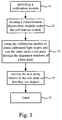
Fig. 1 is a flowchart of a method for aligning a lens array to a cell array according to the preferred embodiment of the present invention. -
Fig. 2 is a top view of a collimation module for use in the method shown inFig. 1 . -
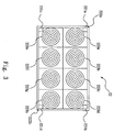
Fig. 3 is a top view of a lens array for use in the method shown inFig. 1 . -
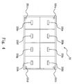
Fig. 4 is a top view of a cell array for use in the method shown inFig. 1 . -
Fig. 5 is an exploded view of the collimation module shown inFig. 2 and a concentration photovoltaic module including the lenses shown inFig. 3 and the solar cells shown inFig. 4 . -
Fig. 6 shows the operation of aligning the lens array to the cell array shown inFig. 5 . - Referring to
Fig. 1 , there is shown a method for aligning alens array 22 to acell array 23 of a concentration photovoltaic module 1 (Fig. 6 ). - Referring to
Figs. 1 and2 , at 11, acollimation module 21 is provided. The collimation unit 2 includes a plurality of collimatedlight sources - Referring to
Figs. 1 ,5 , and6 at 12, the concentrationphotovoltaic module 1 is located under thecollimation unit 21. - Referring to
Fig. 3 , thelens array 22 includes a plurality ofalignment windows alignment apertures concentration lenses lens array 22 is attached to the bottom of thecollimation module 21 so that they are movable together and that thealignment windows 221a to 221d are aligned to the collimatedlight sources 211a to 211 d. - Referring to
Fig. 4 , thecell array 23 includes a plurality ofalignment points solar cells alignment points 231a to 231d are located near the corners of thecell array 23. Thecell array 23 is located under thelens array 22 so that thealignment points 231 a to 231 d are located under thealignment windows 221a to 221d and that they are movable together with each other. - At 13, the
collimation module 21 emits collimatedlight beams Fig. 6 ). The collimated light beams 2a to 2d are preferably laser. The collimated light beams 2a to 2d are cast onto thecell array 23 through thealignment windows 221a to 221d of thelens array 22. - At 14, the
lens array 22 is horizontally moved relative to thecell array 23, i.e., thelens array 22 or thecell array 23 is horizontally moved, so that the collimated light beams 2a to 2d are cast on thealignment points 231a to 231d through thealignment windows 221a to 221 d. - Referring to
Figs. 1 and6 , at 15, thecollimation module 21 collimates the sunlight and casts the collimated light on thelens array 22. Theconcentration lenses 223a to 223h of thelens array 22 concentrate the collimated light into a plurality of light spots and cast the light spots on thesolar cells 232a to 232h of thecell array 23. - As discussed above, optical alignment is used in the present invention. Referring to
Figs. 1 and2 , at 11, thecollimation module 21 is provided. The collimatedlight sources collimation unit 21 cast collimated light beams 2a to 2d onto thealignment points 231a to 231d of thecell array 23 through thealignment windows 221a to 221d of thelens array 22. Thelens array 22 or thecell array 23 is moved so that thealignment windows 221a to 221d are aligned to thealignment points 231a to 231d. Therefore, the axes of the light beams emitted from theconcentration lenses 223a to 223h of thelens array 22 are aligned to the centers of thesolar cells 232a to 232h of thecell array 23. - The optical alignment is conducted without having to complicate the structure of the concentration
photovoltaic module 1. Therefore, the method according to the present invention enables the concentrationphotovoltaic module 1 to efficiently generate electricity at a low cost. - The present invention has been described via the detailed illustration of the preferred embodiment. Those skilled in the art can derive variations from the preferred embodiment without departing from the scope of the present invention. Therefore, the preferred embodiment shall not limit the scope of the present invention defined in the claims.
Claims (3)
- A method for aligning a lens array (22) to a cell array (23) of a concentration photovoltaic module (1), wherein the lens array (22) comprises a plurality of concentration lenses (223a to 223h) and alignment windows (221a to 221d), and the cell array (23) comprises a plurality of solar cells (232a to 232h) and alignment points (231a, 231b, 231c and 231d), said method comprising the steps of:- providing at least one collimation module (21) comprising collimated light sources (211a, 211b, 211c and 211d) to emit collimated light beams;- attaching the lens array (22) to the bottom of the collimation module (21) so that the alignment windows (221a to 221d) of the lens array (22) are located under the collimated light sources (211 a, 211b, 211c and 211d);- locating the cell array (23) under the lens array (22) so that the alignment points of the cell array (231a, 231b, 231c, 231d) are located under the alignment windows (221a to 221d) of the lens array- casting the collimated light beams of said collimated light sources (211a, 211b, 211c and 211d) onto the cell array (23) through the alignment windows (221a to 221d) of the lens array (22); and- adjusting the relative position between the lens array (22) and the cell array (23) so that the collimated light beams, which are passing through the alignment windows (221a to 221 d) of the lens array (22), are directed to the alignment points (231a, 231 b, 231c and 231d) of the cell array (23) resulting in that the axes of the light beams emitted from the concentration lenses (223a to 223h) of the lens array (22) are directed to the centers of the solar cells (232a to 232h) of the cell array (23).
- The method according to claim 1, wherein the alignment points (231a, 231b, 231c and 231d) are located near the corners of the cell array (23).
- The method according to claim 1 or 2, wherein the collimated light sources emit laser light (211a, 211b, 211c and 211d).
Priority Applications (1)
| Application Number | Priority Date | Filing Date | Title |
|---|---|---|---|
| EP07123172.4A EP2071634B1 (en) | 2007-12-13 | 2007-12-13 | Method for aligning a lens array to a solar cell array |
Applications Claiming Priority (1)
| Application Number | Priority Date | Filing Date | Title |
|---|---|---|---|
| EP07123172.4A EP2071634B1 (en) | 2007-12-13 | 2007-12-13 | Method for aligning a lens array to a solar cell array |
Publications (2)
| Publication Number | Publication Date |
|---|---|
| EP2071634A1 EP2071634A1 (en) | 2009-06-17 |
| EP2071634B1 true EP2071634B1 (en) | 2016-06-01 |
Family
ID=39365742
Family Applications (1)
| Application Number | Title | Priority Date | Filing Date |
|---|---|---|---|
| EP07123172.4A Not-in-force EP2071634B1 (en) | 2007-12-13 | 2007-12-13 | Method for aligning a lens array to a solar cell array |
Country Status (1)
| Country | Link |
|---|---|
| EP (1) | EP2071634B1 (en) |
Families Citing this family (2)
| Publication number | Priority date | Publication date | Assignee | Title |
|---|---|---|---|---|
| FR2959601A1 (en) * | 2010-04-28 | 2011-11-04 | Heliotrop | METHOD FOR MANUFACTURING A PANEL WITH A PHOTOVOLTAIC CONCENTRATION |
| DE102013006264A1 (en) * | 2013-04-11 | 2014-10-16 | Grenzebach Maschinenbau Gmbh | Device and method for optimal adjustment of the lens plate in a CPV module |
Family Cites Families (5)
| Publication number | Priority date | Publication date | Assignee | Title |
|---|---|---|---|---|
| DE2757765B1 (en) * | 1977-12-23 | 1979-02-22 | Moebes Nachfl Gmbh & Co Kg W | Solar cell arrangement for generating electrical energy and a solar generator consisting of a plurality of solar cell arrangements and a method for their production |
| JP3163969B2 (en) * | 1995-11-22 | 2001-05-08 | トヨタ自動車株式会社 | Concentrating solar cell device |
| JP3337389B2 (en) * | 1996-12-26 | 2002-10-21 | 株式会社豊田中央研究所 | Concentrating solar cell device |
| US20050081908A1 (en) * | 2003-03-19 | 2005-04-21 | Stewart Roger G. | Method and apparatus for generation of electrical power from solar energy |
| TWI277772B (en) * | 2005-10-28 | 2007-04-01 | Atomic Energy Council | Photovoltaic concentrator apparatus |
-
2007
- 2007-12-13 EP EP07123172.4A patent/EP2071634B1/en not_active Not-in-force
Also Published As
| Publication number | Publication date |
|---|---|
| EP2071634A1 (en) | 2009-06-17 |
Similar Documents
| Publication | Publication Date | Title |
|---|---|---|
| EP2136409A1 (en) | Concentration photovoltaic cell system with light guide | |
| CN203747745U (en) | High light-concentrated solar lighting module group | |
| US20080041441A1 (en) | solar concentrator device for photovoltaic energy generation | |
| US20100123954A1 (en) | Kohler concentrator | |
| US20100218804A1 (en) | Method for aligning a lens array to a cell array | |
| WO2007084518A3 (en) | A hybrid primary optical component for optical concentrators | |
| US20110036388A1 (en) | Tracking drive type solar power generation apparatus | |
| US20230302731A1 (en) | Projection device with combined matrix optical lens and 3d printer | |
| CN101345497A (en) | Curved surface sunlight receiver | |
| CN107153426A (en) | A kind of sun-tracking sensor based on optical fiber light-guiding | |
| US20140090692A1 (en) | Concentrated solar cell and manufacturing method for the same | |
| JPH11136439A (en) | Image sensor and information processing device using the same | |
| KR20130007076A (en) | Concentrating solar cell | |
| JP2013211487A (en) | Secondary lens, solar battery mounting body, condensing type photovoltaic power generation unit, and condensing type photovoltaic power generation module | |
| EP2071634A1 (en) | Method for aligning a lens array to a solar cell array | |
| US20090320901A1 (en) | Concentration photovoltaic cell system with light guide | |
| CN101388625A (en) | Solar concentration electricity generating apparatus | |
| KR101412533B1 (en) | Concentrating Photovoltaics Apparatus Having Non-Powered Solar Light Tracking Function | |
| KR101616757B1 (en) | Device for concentrating optical radiation for localized heating by automatic solar tracking | |
| US20110283517A1 (en) | Method for Aligning a Lens Array to a Cell Array | |
| US8835746B2 (en) | Device for aligning a concentration photovoltaic module | |
| JP2006332113A (en) | Concentrating solar power generation module and concentrating solar power generation device | |
| CN101170291A (en) | A solar device with parallel refraction lens | |
| JP4571175B2 (en) | Concentrating solar power module alignment method | |
| US20120206826A1 (en) | Light-collecting device and light-collecting method thereof |
Legal Events
| Date | Code | Title | Description |
|---|---|---|---|
| PUAI | Public reference made under article 153(3) epc to a published international application that has entered the european phase |
Free format text: ORIGINAL CODE: 0009012 |
|
| 17P | Request for examination filed |
Effective date: 20080114 |
|
| AK | Designated contracting states |
Kind code of ref document: A1 Designated state(s): AT BE BG CH CY CZ DE DK EE ES FI FR GB GR HU IE IS IT LI LT LU LV MC MT NL PL PT RO SE SI SK TR |
|
| AX | Request for extension of the european patent |
Extension state: AL BA HR MK RS |
|
| 17Q | First examination report despatched |
Effective date: 20100119 |
|
| AKX | Designation fees paid |
Designated state(s): AT BE BG CH CY CZ DE DK EE ES FI FR GB GR HU IE IS IT LI LT LU LV MC MT NL PL PT RO SE SI SK TR |
|
| REG | Reference to a national code |
Ref country code: DE Ref legal event code: R079 Ref document number: 602007046499 Country of ref document: DE Free format text: PREVIOUS MAIN CLASS: H01L0031052000 Ipc: H01L0031054000 |
|
| GRAP | Despatch of communication of intention to grant a patent |
Free format text: ORIGINAL CODE: EPIDOSNIGR1 |
|
| RIC1 | Information provided on ipc code assigned before grant |
Ipc: H01L 31/054 20140101AFI20160120BHEP |
|
| INTG | Intention to grant announced |
Effective date: 20160202 |
|
| GRAS | Grant fee paid |
Free format text: ORIGINAL CODE: EPIDOSNIGR3 |
|
| GRAA | (expected) grant |
Free format text: ORIGINAL CODE: 0009210 |
|
| AK | Designated contracting states |
Kind code of ref document: B1 Designated state(s): AT BE BG CH CY CZ DE DK EE ES FI FR GB GR HU IE IS IT LI LT LU LV MC MT NL PL PT RO SE SI SK TR |
|
| REG | Reference to a national code |
Ref country code: GB Ref legal event code: FG4D |
|
| REG | Reference to a national code |
Ref country code: CH Ref legal event code: EP Ref country code: AT Ref legal event code: REF Ref document number: 804337 Country of ref document: AT Kind code of ref document: T Effective date: 20160615 |
|
| REG | Reference to a national code |
Ref country code: IE Ref legal event code: FG4D |
|
| REG | Reference to a national code |
Ref country code: DE Ref legal event code: R096 Ref document number: 602007046499 Country of ref document: DE |
|
| REG | Reference to a national code |
Ref country code: LT Ref legal event code: MG4D |
|
| REG | Reference to a national code |
Ref country code: NL Ref legal event code: MP Effective date: 20160601 |
|
| PG25 | Lapsed in a contracting state [announced via postgrant information from national office to epo] |
Ref country code: LT Free format text: LAPSE BECAUSE OF FAILURE TO SUBMIT A TRANSLATION OF THE DESCRIPTION OR TO PAY THE FEE WITHIN THE PRESCRIBED TIME-LIMIT Effective date: 20160601 Ref country code: FI Free format text: LAPSE BECAUSE OF FAILURE TO SUBMIT A TRANSLATION OF THE DESCRIPTION OR TO PAY THE FEE WITHIN THE PRESCRIBED TIME-LIMIT Effective date: 20160601 |
|
| REG | Reference to a national code |
Ref country code: AT Ref legal event code: MK05 Ref document number: 804337 Country of ref document: AT Kind code of ref document: T Effective date: 20160601 |
|
| PG25 | Lapsed in a contracting state [announced via postgrant information from national office to epo] |
Ref country code: NL Free format text: LAPSE BECAUSE OF FAILURE TO SUBMIT A TRANSLATION OF THE DESCRIPTION OR TO PAY THE FEE WITHIN THE PRESCRIBED TIME-LIMIT Effective date: 20160601 Ref country code: LV Free format text: LAPSE BECAUSE OF FAILURE TO SUBMIT A TRANSLATION OF THE DESCRIPTION OR TO PAY THE FEE WITHIN THE PRESCRIBED TIME-LIMIT Effective date: 20160601 Ref country code: GR Free format text: LAPSE BECAUSE OF FAILURE TO SUBMIT A TRANSLATION OF THE DESCRIPTION OR TO PAY THE FEE WITHIN THE PRESCRIBED TIME-LIMIT Effective date: 20160902 Ref country code: ES Free format text: LAPSE BECAUSE OF FAILURE TO SUBMIT A TRANSLATION OF THE DESCRIPTION OR TO PAY THE FEE WITHIN THE PRESCRIBED TIME-LIMIT Effective date: 20160601 Ref country code: SE Free format text: LAPSE BECAUSE OF FAILURE TO SUBMIT A TRANSLATION OF THE DESCRIPTION OR TO PAY THE FEE WITHIN THE PRESCRIBED TIME-LIMIT Effective date: 20160601 |
|
| PG25 | Lapsed in a contracting state [announced via postgrant information from national office to epo] |
Ref country code: IT Free format text: LAPSE BECAUSE OF FAILURE TO SUBMIT A TRANSLATION OF THE DESCRIPTION OR TO PAY THE FEE WITHIN THE PRESCRIBED TIME-LIMIT Effective date: 20160601 Ref country code: CZ Free format text: LAPSE BECAUSE OF FAILURE TO SUBMIT A TRANSLATION OF THE DESCRIPTION OR TO PAY THE FEE WITHIN THE PRESCRIBED TIME-LIMIT Effective date: 20160601 Ref country code: IS Free format text: LAPSE BECAUSE OF FAILURE TO SUBMIT A TRANSLATION OF THE DESCRIPTION OR TO PAY THE FEE WITHIN THE PRESCRIBED TIME-LIMIT Effective date: 20161001 Ref country code: RO Free format text: LAPSE BECAUSE OF FAILURE TO SUBMIT A TRANSLATION OF THE DESCRIPTION OR TO PAY THE FEE WITHIN THE PRESCRIBED TIME-LIMIT Effective date: 20160601 Ref country code: SK Free format text: LAPSE BECAUSE OF FAILURE TO SUBMIT A TRANSLATION OF THE DESCRIPTION OR TO PAY THE FEE WITHIN THE PRESCRIBED TIME-LIMIT Effective date: 20160601 Ref country code: EE Free format text: LAPSE BECAUSE OF FAILURE TO SUBMIT A TRANSLATION OF THE DESCRIPTION OR TO PAY THE FEE WITHIN THE PRESCRIBED TIME-LIMIT Effective date: 20160601 |
|
| PG25 | Lapsed in a contracting state [announced via postgrant information from national office to epo] |
Ref country code: BE Free format text: LAPSE BECAUSE OF FAILURE TO SUBMIT A TRANSLATION OF THE DESCRIPTION OR TO PAY THE FEE WITHIN THE PRESCRIBED TIME-LIMIT Effective date: 20160601 Ref country code: PL Free format text: LAPSE BECAUSE OF FAILURE TO SUBMIT A TRANSLATION OF THE DESCRIPTION OR TO PAY THE FEE WITHIN THE PRESCRIBED TIME-LIMIT Effective date: 20160601 Ref country code: AT Free format text: LAPSE BECAUSE OF FAILURE TO SUBMIT A TRANSLATION OF THE DESCRIPTION OR TO PAY THE FEE WITHIN THE PRESCRIBED TIME-LIMIT Effective date: 20160601 Ref country code: PT Free format text: LAPSE BECAUSE OF FAILURE TO SUBMIT A TRANSLATION OF THE DESCRIPTION OR TO PAY THE FEE WITHIN THE PRESCRIBED TIME-LIMIT Effective date: 20161003 |
|
| REG | Reference to a national code |
Ref country code: DE Ref legal event code: R097 Ref document number: 602007046499 Country of ref document: DE |
|
| PLBE | No opposition filed within time limit |
Free format text: ORIGINAL CODE: 0009261 |
|
| STAA | Information on the status of an ep patent application or granted ep patent |
Free format text: STATUS: NO OPPOSITION FILED WITHIN TIME LIMIT |
|
| PGFP | Annual fee paid to national office [announced via postgrant information from national office to epo] |
Ref country code: DE Payment date: 20161231 Year of fee payment: 10 |
|
| 26N | No opposition filed |
Effective date: 20170302 |
|
| PG25 | Lapsed in a contracting state [announced via postgrant information from national office to epo] |
Ref country code: SI Free format text: LAPSE BECAUSE OF FAILURE TO SUBMIT A TRANSLATION OF THE DESCRIPTION OR TO PAY THE FEE WITHIN THE PRESCRIBED TIME-LIMIT Effective date: 20160601 Ref country code: DK Free format text: LAPSE BECAUSE OF FAILURE TO SUBMIT A TRANSLATION OF THE DESCRIPTION OR TO PAY THE FEE WITHIN THE PRESCRIBED TIME-LIMIT Effective date: 20160601 |
|
| REG | Reference to a national code |
Ref country code: CH Ref legal event code: PL |
|
| GBPC | Gb: european patent ceased through non-payment of renewal fee |
Effective date: 20161213 |
|
| PG25 | Lapsed in a contracting state [announced via postgrant information from national office to epo] |
Ref country code: MC Free format text: LAPSE BECAUSE OF FAILURE TO SUBMIT A TRANSLATION OF THE DESCRIPTION OR TO PAY THE FEE WITHIN THE PRESCRIBED TIME-LIMIT Effective date: 20160601 |
|
| REG | Reference to a national code |
Ref country code: FR Ref legal event code: ST Effective date: 20170831 |
|
| REG | Reference to a national code |
Ref country code: IE Ref legal event code: MM4A |
|
| PG25 | Lapsed in a contracting state [announced via postgrant information from national office to epo] |
Ref country code: FR Free format text: LAPSE BECAUSE OF NON-PAYMENT OF DUE FEES Effective date: 20170102 Ref country code: CH Free format text: LAPSE BECAUSE OF NON-PAYMENT OF DUE FEES Effective date: 20161231 Ref country code: LU Free format text: LAPSE BECAUSE OF NON-PAYMENT OF DUE FEES Effective date: 20161213 Ref country code: LI Free format text: LAPSE BECAUSE OF NON-PAYMENT OF DUE FEES Effective date: 20161231 |
|
| PG25 | Lapsed in a contracting state [announced via postgrant information from national office to epo] |
Ref country code: GB Free format text: LAPSE BECAUSE OF NON-PAYMENT OF DUE FEES Effective date: 20161213 Ref country code: IE Free format text: LAPSE BECAUSE OF NON-PAYMENT OF DUE FEES Effective date: 20161213 |
|
| PG25 | Lapsed in a contracting state [announced via postgrant information from national office to epo] |
Ref country code: HU Free format text: LAPSE BECAUSE OF FAILURE TO SUBMIT A TRANSLATION OF THE DESCRIPTION OR TO PAY THE FEE WITHIN THE PRESCRIBED TIME-LIMIT; INVALID AB INITIO Effective date: 20071213 Ref country code: CY Free format text: LAPSE BECAUSE OF FAILURE TO SUBMIT A TRANSLATION OF THE DESCRIPTION OR TO PAY THE FEE WITHIN THE PRESCRIBED TIME-LIMIT Effective date: 20160601 |
|
| PG25 | Lapsed in a contracting state [announced via postgrant information from national office to epo] |
Ref country code: TR Free format text: LAPSE BECAUSE OF FAILURE TO SUBMIT A TRANSLATION OF THE DESCRIPTION OR TO PAY THE FEE WITHIN THE PRESCRIBED TIME-LIMIT Effective date: 20160601 |
|
| REG | Reference to a national code |
Ref country code: DE Ref legal event code: R119 Ref document number: 602007046499 Country of ref document: DE |
|
| PG25 | Lapsed in a contracting state [announced via postgrant information from national office to epo] |
Ref country code: BG Free format text: LAPSE BECAUSE OF FAILURE TO SUBMIT A TRANSLATION OF THE DESCRIPTION OR TO PAY THE FEE WITHIN THE PRESCRIBED TIME-LIMIT Effective date: 20160601 |
|
| PG25 | Lapsed in a contracting state [announced via postgrant information from national office to epo] |
Ref country code: MT Free format text: LAPSE BECAUSE OF NON-PAYMENT OF DUE FEES Effective date: 20161213 |
|
| PG25 | Lapsed in a contracting state [announced via postgrant information from national office to epo] |
Ref country code: DE Free format text: LAPSE BECAUSE OF NON-PAYMENT OF DUE FEES Effective date: 20180703 |