EP2071566A1 - Sync mark correction for holographic data pages - Google Patents
Sync mark correction for holographic data pages Download PDFInfo
- Publication number
- EP2071566A1 EP2071566A1 EP08305886A EP08305886A EP2071566A1 EP 2071566 A1 EP2071566 A1 EP 2071566A1 EP 08305886 A EP08305886 A EP 08305886A EP 08305886 A EP08305886 A EP 08305886A EP 2071566 A1 EP2071566 A1 EP 2071566A1
- Authority
- EP
- European Patent Office
- Prior art keywords
- sync mark
- sync
- data
- marks
- data page
- Prior art date
- Legal status (The legal status is an assumption and is not a legal conclusion. Google has not performed a legal analysis and makes no representation as to the accuracy of the status listed.)
- Granted
Links
- 238000000034 method Methods 0.000 claims abstract description 23
- 238000013500 data storage Methods 0.000 claims abstract description 13
- 230000003287 optical effect Effects 0.000 claims abstract description 13
- 238000001514 detection method Methods 0.000 claims description 13
- 230000007547 defect Effects 0.000 description 4
- 239000000463 material Substances 0.000 description 3
- 230000001427 coherent effect Effects 0.000 description 2
- 238000004364 calculation method Methods 0.000 description 1
- 238000005352 clarification Methods 0.000 description 1
- 238000001914 filtration Methods 0.000 description 1
- 239000011159 matrix material Substances 0.000 description 1
- 238000012986 modification Methods 0.000 description 1
- 230000004048 modification Effects 0.000 description 1
- 239000011232 storage material Substances 0.000 description 1
Images



Classifications
-
- G—PHYSICS
- G11—INFORMATION STORAGE
- G11B—INFORMATION STORAGE BASED ON RELATIVE MOVEMENT BETWEEN RECORD CARRIER AND TRANSDUCER
- G11B7/00—Recording or reproducing by optical means, e.g. recording using a thermal beam of optical radiation by modifying optical properties or the physical structure, reproducing using an optical beam at lower power by sensing optical properties; Record carriers therefor
- G11B7/004—Recording, reproducing or erasing methods; Read, write or erase circuits therefor
- G11B7/0065—Recording, reproducing or erasing by using optical interference patterns, e.g. holograms
-
- G—PHYSICS
- G11—INFORMATION STORAGE
- G11B—INFORMATION STORAGE BASED ON RELATIVE MOVEMENT BETWEEN RECORD CARRIER AND TRANSDUCER
- G11B7/00—Recording or reproducing by optical means, e.g. recording using a thermal beam of optical radiation by modifying optical properties or the physical structure, reproducing using an optical beam at lower power by sensing optical properties; Record carriers therefor
- G11B7/004—Recording, reproducing or erasing methods; Read, write or erase circuits therefor
- G11B7/005—Reproducing
-
- G—PHYSICS
- G11—INFORMATION STORAGE
- G11B—INFORMATION STORAGE BASED ON RELATIVE MOVEMENT BETWEEN RECORD CARRIER AND TRANSDUCER
- G11B7/00—Recording or reproducing by optical means, e.g. recording using a thermal beam of optical radiation by modifying optical properties or the physical structure, reproducing using an optical beam at lower power by sensing optical properties; Record carriers therefor
- G11B7/007—Arrangement of the information on the record carrier, e.g. form of tracks, actual track shape, e.g. wobbled, or cross-section, e.g. v-shaped; Sequential information structures, e.g. sectoring or header formats within a track
- G11B7/00772—Arrangement of the information on the record carrier, e.g. form of tracks, actual track shape, e.g. wobbled, or cross-section, e.g. v-shaped; Sequential information structures, e.g. sectoring or header formats within a track on record carriers storing information in the form of optical interference patterns, e.g. holograms
- G11B7/00781—Auxiliary information, e.g. index marks, address marks, pre-pits, gray codes
-
- G—PHYSICS
- G11—INFORMATION STORAGE
- G11B—INFORMATION STORAGE BASED ON RELATIVE MOVEMENT BETWEEN RECORD CARRIER AND TRANSDUCER
- G11B7/00—Recording or reproducing by optical means, e.g. recording using a thermal beam of optical radiation by modifying optical properties or the physical structure, reproducing using an optical beam at lower power by sensing optical properties; Record carriers therefor
- G11B7/08—Disposition or mounting of heads or light sources relatively to record carriers
- G11B7/09—Disposition or mounting of heads or light sources relatively to record carriers with provision for moving the light beam or focus plane for the purpose of maintaining alignment of the light beam relative to the record carrier during transducing operation, e.g. to compensate for surface irregularities of the latter or for track following
Definitions
- the present invention relates to a method for reading data from a data page for optical data storage in an optical storage system, e.g. a holographic storage system, including the correction of missing or wrong positioned sync marks, and to an apparatus for reading from an optical storage medium performing this method.
- an optical storage system e.g. a holographic storage system, including the correction of missing or wrong positioned sync marks
- holographic data storage digital data are stored by encoding the interference pattern produced by the superposition of two coherent laser beams, where one beam, the so-called 'object-beam', is modulated by a spatial light modulator (SLM) and carries the information to be recorded.
- SLM spatial light modulator
- the second beam serves as a reference beam.
- the interference pattern leads to modifications of specific properties of the storage material, which depend on the local intensity of the interference pattern. Reading of a recorded hologram is performed by illuminating the hologram with the reference beam using the same conditions as during recoding. This results in the reconstruction of the recorded object beam.
- holographic data storage is an increased data capacity. Contrary to conventional optical storage media, the volume of the holographic storage medium is used for storing information, not just a single or few two-dimensional layers.
- One further advantage of holographic data storage is the possibility to store multiple data in the same volume, e.g. by changing the angle between the two beams or by using shift multiplexing, etc.
- data are stored as data pages.
- a data page consists of a matrix of light intensity variations, i.e. a two-dimensional binary array or an array of grey values, which code multiple bits.
- Data pages consisting of patterns showing different phases can also be used. This allows achieving increased data rates in addition to the increased storage density.
- the data page is imprinted onto the object beam by the SLM and detected with a detector array.
- Data pages include synchronisation marks, also referred to as sync marks, to determine the exact scaling factor from the SLM to the detector and to correct image distortion.
- Sync marks usually consist of a specific bit pattern, which is known and can be identified clearly by the reading apparatus.
- the correct sync mark detection is essential for a successful demodulation procedure.
- the scaling factor and the image distortion can vary locally, sync marks are usually distributed over the entire data page. If the sync mark detection fails in a part of the data page then in most cases the demodulation will also fail in this region. Due to defects in the holographic material or distortions such as detector noise the correct detection of a local sync mark may fail.
- the method for reading data from a data page from an optical data storage medium has the steps of:
- the method is used for reading from a holographic data storage medium.
- data are stored using two-dimensional data pages.
- further data processing includes data detection in the region of the missing or wrong positioned sync mark using the estimated sync mark position. Data is read out reliably essentially independent from wrong positioned or missing sync marks.
- wrong positioned or missing sync marks are corrected by estimating their correct position by interpolating sync marks from corresponding rows and/or columns.
- Sync mark positions are estimated, e.g. by the intersection of two regression curves of the corresponding row and column. This leads to an accurate estimation of the corrected sync mark position.
- the corrected sync mark position is estimated by interpolating sync marks from a set of sync marks nearby.
- other sync marks are used to determine the correct position of the wrong positioned or missing sync mark. Consequently, local differences of the optical path and of the optical elements are considered during estimation of the corrected sync mark position.
- a measure for the deviation of a sync mark position from its expected position is calculated to detect wrong positioned or missing sync marks.
- the measure is calculated, for example, using regression curves of the corresponding row or column, or the measure is calculated using other sync marks within a defined area around an estimated sync mark position.
- the mathematical measure is calculated, for example, using quadratic filtering of the read out sync marks or using the statistical variance of the sync mark positions.
- the mathematical measure can be adapted to an algorithm which fits best to the system configuration.
- the invention is flexible and adjustable to the basic conditions.
- a data area around a wrong positioned sync mark is shifted according to a sync mark deviation. This improves read out accuracy.
- an apparatus for reading a data storage media uses a method according to the invention for detecting missing or wrong positioned sync marks and correcting the sync mark positions.
- the sync marks have a light intensity distribution and a spatial frequency distribution similar to the light intensity and spatial frequency distribution of the data blocks.
- a similar light intensity and spatial frequency distribution over the whole data page leads to a more uniform utilization of the holographic material resulting in a higher storage capacity.
- the light intensity of the sync marks can be reduced and adapted to the light intensity distribution of the whole data page.
- the sync mark detection errors resulting from the lower light intensity of the sync marks are corrected by the invention.
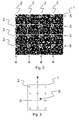
- Fig. 1 schematically depicts a part of a data page 1 including two rows 5 and three columns 4 of sync marks 2.
- a sync mark 2 is composed of e.g. a 5x5 pixel pattern. Different sync marks 2 can be used and distributed over the data page 1 to put additional information into the sync marks 2.
- the sync mark detection is realized e.g. by searching for local maxima in the correlation of the read out data page and the sync mark pattern.
- the distance between two adjacent sync mark columns 4 is dx.
- the distance between two adjacent sync mark rows 5 is dy.
- the offset from the upper left corner of the data page 1 to the first sync mark position is ox and oy, respectively.
- Data blocks 3 are indicated schematically by dots.
- Fig. 2 shows an example of a part of a data page 1 as a combination of digital patterns.
- a pattern like this is imprinted on an SLM during writing.
- Sync marks 2 have a specific shape and can be retrieved from the figure.
- This data page 1 contains four sync marks 2 in a row 5 and four sync marks in a column 4.
- sync marks 2 are equally spaced.
- the positions of the sync marks 2 on a data page 1 and the pattern of the sync marks 2 are also known in advance by the reading apparatus.
- the white lines are for clarification only and divide the data page 1 into subpages, each one containing 4x4 blocks.
- One of the blocks is a sync block 2.
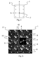
- Fig. 3 schematically shows a part of a data page 1, including sync marks 2 arranged in rows 5 and columns 4.
- the dotted lines indicate a row 5 and a column 4 of sync marks. They are not the same as the lines indicated in Fig. 2 showing the subpages.
- the correct detection of the sync mark failed.
- Sync marks in row 5 and column 4 are assumed to be detected correctly.
- the expected position of sync mark 6 is at the intersection point of the interpolation curves of sync marks in row 5 and column 4.
- the distance of a sync mark 6 from the expected position for this sync mark can be expressed by a mathematical measure, e.g. the variance. If this measure exceeds a certain limit, it is assumed that the sync mark detection failed.
- the corrected position of the sync mark is estimated to be at the intersection point of the interpolation curves of the correctly detected sync marks.
- the sync mark which was identified to be detected at a wrong position is shifted to this intersection point.
- Fig. 4 shows the replacement of the sync mark 7.
- Fig. 5 shows an example of the detected data pattern depicted in Fig. 2 .
- Sync marks 2 can be identified in the picture as bright areas.
- sync marks 2 have a higher ratio between 'on' and 'off' pixels compared to a data block 3. Nevertheless, on a detected data page, they cannot be identified by eye.
- the data page 1 shown in Fig. 5 uses sync marks 2 with an even higher light intensity compared to the data blocks 3 for demonstration purposes only.
- the distance between two adjacent sync marks 2 is known in advance. Therefore, a grid 9 can be established on a data page 1. Between four neighbouring grid points 9, a sync mark 2 has to be detected. In case a part of the data page 8 is not detected correctly, also the sync mark detection within this area fails. This can be caused e.g. due to a bad signal-to-noise ratio (SNR), local defects in the holographic material or local defects of the detector or the optical apparatus. Without using the method according to the invention, in the area 11 between four neighbouring grid points 9 the sync mark 7 is not readable. The sync mark is determined at a data block 6 which looks most similar to a sync pattern.
- SNR signal-to-noise ratio
- Fig. 6 shows a data page 1 using sync marks 2 with a light intensity and a spatial frequency distribution similar to the light intensity and spatial frequency distribution of the whole data page 1.
- the sync marks 2 can not be identified by eye.
- the SNR on the sync mark 2 is worse compared to the SNR of the sync marks 2 shown in Fig. 5 .
- FIG. 7 an apparatus 20 for reading and/or recording a holographic storage medium 29 is shown schematically.
- a source of coherent light e.g. a laser diode 21, emits a light beam 22, which is collimated by a collimating lens 23.
- the light beam 22 is then divided into two separate light beams 26, 27.
- the division of the light beam 22 is achieved using a first beam splitter 24.
- a spatial light modulator (SLM) 25 modulates one of the two beams, the so called “object beam” 26, to imprint a two-dimensional data pattern.
- Both the object beam 26 and the further beam, the so called “reference beam” 27 are focused into a holographic storage medium 29, e.g. a holographic disk or card, by an objective lens 28.
- a holographic storage medium 29 e.g. a holographic disk or card
- the stored data are retrieved from the holographic storage medium 29 by illuminating a recorded hologram with the reference beam 27 only.
- the reference beam 27 is diffracted by the hologram structure and produces a copy of the original object beam 26, the reconstructed object beam 30.
- This reconstructed object beam 30 is collimated by the objective lens 28 and directed onto a two-dimensional array detector 32, e.g. a CCD-array, by a second beam splitter 31.
- the array detector 32 allows to reconstruct the recorded data.
Landscapes
- Holo Graphy (AREA)
- Optical Recording Or Reproduction (AREA)
- Signal Processing For Digital Recording And Reproducing (AREA)
Abstract
Description
- The present invention relates to a method for reading data from a data page for optical data storage in an optical storage system, e.g. a holographic storage system, including the correction of missing or wrong positioned sync marks, and to an apparatus for reading from an optical storage medium performing this method.
- The invention is described below using a holographic storage system as an example. It is apparent to a person skilled in the art that the invention is applicable within other optical storage systems.
- In holographic data storage digital data are stored by encoding the interference pattern produced by the superposition of two coherent laser beams, where one beam, the so-called 'object-beam', is modulated by a spatial light modulator (SLM) and carries the information to be recorded. The second beam serves as a reference beam. The interference pattern leads to modifications of specific properties of the storage material, which depend on the local intensity of the interference pattern. Reading of a recorded hologram is performed by illuminating the hologram with the reference beam using the same conditions as during recoding. This results in the reconstruction of the recorded object beam.
- One advantage of holographic data storage is an increased data capacity. Contrary to conventional optical storage media, the volume of the holographic storage medium is used for storing information, not just a single or few two-dimensional layers. One further advantage of holographic data storage is the possibility to store multiple data in the same volume, e.g. by changing the angle between the two beams or by using shift multiplexing, etc. Furthermore, instead of storing single bits, data are stored as data pages. Typically a data page consists of a matrix of light intensity variations, i.e. a two-dimensional binary array or an array of grey values, which code multiple bits. Data pages consisting of patterns showing different phases can also be used. This allows achieving increased data rates in addition to the increased storage density. The data page is imprinted onto the object beam by the SLM and detected with a detector array.
- Data pages include synchronisation marks, also referred to as sync marks, to determine the exact scaling factor from the SLM to the detector and to correct image distortion. Sync marks usually consist of a specific bit pattern, which is known and can be identified clearly by the reading apparatus. For any holographic data storage system the correct sync mark detection is essential for a successful demodulation procedure. As the scaling factor and the image distortion can vary locally, sync marks are usually distributed over the entire data page. If the sync mark detection fails in a part of the data page then in most cases the demodulation will also fail in this region. Due to defects in the holographic material or distortions such as detector noise the correct detection of a local sync mark may fail.
- It is an object of the invention to propose a method for detecting such failures and/or correcting wrong positioned or missing sync marks. Readout is improved by using estimated sync marks.
- According to the invention, the method for reading data from a data page from an optical data storage medium has the steps of:
- identifying at least one missing or wrong positioned sync mark on a read data page,
- estimating a corrected sync mark position, and
- using the estimated corrected sync mark position for further processing.
- According to this method, wrong positioned or missing sync marks can be identified even if a number of sync mark detections failed. Nevertheless, it is assumed that most of the sync marks are detected correctly to provide a basis for the calculation of the estimated corrected sync mark position. Using the proposed sync mark correction allows to determine image distortion and locally varying scaling factors on a data page reliably. The method is numerically simple and efficient. It can be implemented independent from the underlying modulation scheme of a data page. After the replacement the possibility to demodulate the data correctly in the region of the formerly wrong positioned sync mark increases. The bit error rate is reduced.
- Advantageously, the method is used for reading from a holographic data storage medium. In a holographic data storage system, data are stored using two-dimensional data pages. In this case, it is of particular importance to determine image distortion and locally varying scaling factors previous to demodulation. To perform this determination reliably, correct sync mark positions are needed. Increasing the accuracy of the sync mark detection increases the reliability of the readout process.
- Advantageously, further data processing according to the invention includes data detection in the region of the missing or wrong positioned sync mark using the estimated sync mark position. Data is read out reliably essentially independent from wrong positioned or missing sync marks.
- Favourably, wrong positioned or missing sync marks are corrected by estimating their correct position by interpolating sync marks from corresponding rows and/or columns. Sync mark positions are estimated, e.g. by the intersection of two regression curves of the corresponding row and column. This leads to an accurate estimation of the corrected sync mark position.
- Advantageously, the corrected sync mark position is estimated by interpolating sync marks from a set of sync marks nearby. Within a defined area around a wrong positioned or missing sync mark, other sync marks are used to determine the correct position of the wrong positioned or missing sync mark. Consequently, local differences of the optical path and of the optical elements are considered during estimation of the corrected sync mark position.
- Favourably, a measure for the deviation of a sync mark position from its expected position is calculated to detect wrong positioned or missing sync marks. The measure is calculated, for example, using regression curves of the corresponding row or column, or the measure is calculated using other sync marks within a defined area around an estimated sync mark position. The mathematical measure is calculated, for example, using quadratic filtering of the read out sync marks or using the statistical variance of the sync mark positions. The mathematical measure can be adapted to an algorithm which fits best to the system configuration. The invention is flexible and adjustable to the basic conditions.
- Favourably, a data area around a wrong positioned sync mark is shifted according to a sync mark deviation. This improves read out accuracy.
- According to a further aspect of the invention an apparatus for reading a data storage media uses a method according to the invention for detecting missing or wrong positioned sync marks and correcting the sync mark positions.
- Favourably, in a holographic storage medium the sync marks have a light intensity distribution and a spatial frequency distribution similar to the light intensity and spatial frequency distribution of the data blocks. A similar light intensity and spatial frequency distribution over the whole data page leads to a more uniform utilization of the holographic material resulting in a higher storage capacity. Using the method for sync mark detection according to the invention, the light intensity of the sync marks can be reduced and adapted to the light intensity distribution of the whole data page. The sync mark detection errors resulting from the lower light intensity of the sync marks are corrected by the invention.
- For better understanding the invention shall now be explained in more detail in the following description with reference to the figures. It is understood that the invention is not limited to this exemplary embodiment and that specified features can also expediently be combined and/or modified without departing from the scope of the present invention.
- Fig. 1
- schematically shows a data page including sync marks and data blocks,
- Fig. 2
- shows a data page, including four rows and four columns of sync marks,
- Fig. 3
- shows a part of a data page, including one wrong positioned sync mark,
- Fig. 4
- shows a part of a data page, including the corrected position of a sync mark,
- Fig. 5
- shows an example of the replacement of a wrong positioned or missing sync mark within a data page.
- Fig. 6
- shows a read out data page that has sync marks with a light intensity similar to the light intensity of the data page
- Fig. 7
- schematically shows an apparatus for reading and/or recording a holographic storage medium.
-
Fig. 1 schematically depicts a part of adata page 1 including tworows 5 and threecolumns 4 of sync marks 2. Async mark 2 is composed of e.g. a 5x5 pixel pattern. Different sync marks 2 can be used and distributed over thedata page 1 to put additional information into the sync marks 2. The sync mark detection is realized e.g. by searching for local maxima in the correlation of the read out data page and the sync mark pattern. The distance between two adjacentsync mark columns 4 is dx. The distance between two adjacentsync mark rows 5 is dy. The offset from the upper left corner of thedata page 1 to the first sync mark position is ox and oy, respectively. Data blocks 3 are indicated schematically by dots. -
Fig. 2 shows an example of a part of adata page 1 as a combination of digital patterns. A pattern like this is imprinted on an SLM during writing. Sync marks 2 have a specific shape and can be retrieved from the figure. Thisdata page 1 contains foursync marks 2 in arow 5 and four sync marks in acolumn 4. In this example, sync marks 2 are equally spaced. The positions of the sync marks 2 on adata page 1 and the pattern of the sync marks 2 are also known in advance by the reading apparatus. The white lines are for clarification only and divide thedata page 1 into subpages, each one containing 4x4 blocks. One of the blocks is async block 2. -
Fig. 3 schematically shows a part of adata page 1, including sync marks 2 arranged inrows 5 andcolumns 4. The dotted lines indicate arow 5 and acolumn 4 of sync marks. They are not the same as the lines indicated inFig. 2 showing the subpages. There is one wrong positionedsync mark 6 indicated. The correct detection of the sync mark failed. Sync marks inrow 5 andcolumn 4 are assumed to be detected correctly. The expected position ofsync mark 6 is at the intersection point of the interpolation curves of sync marks inrow 5 andcolumn 4. The distance of async mark 6 from the expected position for this sync mark can be expressed by a mathematical measure, e.g. the variance. If this measure exceeds a certain limit, it is assumed that the sync mark detection failed. In this case, the corrected position of the sync mark is estimated to be at the intersection point of the interpolation curves of the correctly detected sync marks. The sync mark which was identified to be detected at a wrong position is shifted to this intersection point.Fig. 4 shows the replacement of thesync mark 7. -
Fig. 5 shows an example of the detected data pattern depicted inFig. 2 . Sync marks 2 can be identified in the picture as bright areas. Generally, sync marks 2 have a higher ratio between 'on' and 'off' pixels compared to adata block 3. Nevertheless, on a detected data page, they cannot be identified by eye. Thedata page 1 shown inFig. 5 uses sync marks 2 with an even higher light intensity compared to the data blocks 3 for demonstration purposes only. - The distance between two adjacent sync marks 2 is known in advance. Therefore, a
grid 9 can be established on adata page 1. Between four neighbouring grid points 9, async mark 2 has to be detected. In case a part of thedata page 8 is not detected correctly, also the sync mark detection within this area fails. This can be caused e.g. due to a bad signal-to-noise ratio (SNR), local defects in the holographic material or local defects of the detector or the optical apparatus. Without using the method according to the invention, in thearea 11 between four neighbouring grid points 9 thesync mark 7 is not readable. The sync mark is determined at adata block 6 which looks most similar to a sync pattern. All foursubpages 10 using theerroneous sync mark 6 as a boundary show significant read errors. In contrast, using a correctedsync mark 7 according to the invention allows reading all data within the four surroundingsubpages 10 except for the data in thedefect region 8. A significantly reduced error rate arises. -
Fig. 6 shows adata page 1 usingsync marks 2 with a light intensity and a spatial frequency distribution similar to the light intensity and spatial frequency distribution of thewhole data page 1. The sync marks 2 can not be identified by eye. The SNR on thesync mark 2 is worse compared to the SNR of the sync marks 2 shown inFig. 5 . - In
Fig. 7 anapparatus 20 for reading and/or recording aholographic storage medium 29 is shown schematically. A source of coherent light, e.g. alaser diode 21, emits alight beam 22, which is collimated by a collimatinglens 23. Thelight beam 22 is then divided into two separatelight beams light beam 22 is achieved using afirst beam splitter 24. However, it is likewise possible to use other optical components for this purpose. A spatial light modulator (SLM) 25 modulates one of the two beams, the so called "object beam" 26, to imprint a two-dimensional data pattern. Both theobject beam 26 and the further beam, the so called "reference beam" 27, are focused into aholographic storage medium 29, e.g. a holographic disk or card, by anobjective lens 28. At the intersection of theobject beam 26 and thereference beam 27 an interference pattern appears, which is recorded in a photo-sensitive layer of theholographic storage medium 29. - The stored data are retrieved from the
holographic storage medium 29 by illuminating a recorded hologram with thereference beam 27 only. Thereference beam 27 is diffracted by the hologram structure and produces a copy of theoriginal object beam 26, the reconstructedobject beam 30. Thisreconstructed object beam 30 is collimated by theobjective lens 28 and directed onto a two-dimensional array detector 32, e.g. a CCD-array, by asecond beam splitter 31. Thearray detector 32 allows to reconstruct the recorded data.
Claims (8)
- Method for reading data from a data page from an optical data storage medium, having the steps of:- identifying at least one missing or wrong positioned sync mark on a read data page;- estimating a corrected sync mark position; and- using the estimated corrected sync mark position for further processing.
- Method according to claim 1, wherein the method is used for reading from a holographic data storage medium.
- Method according to claim 1 or 2, wherein the further data processing includes data detection in the region of the missing or wrong positioned sync mark using the estimated sync mark position.
- Method according to one of the preceding claims, wherein the corrected sync mark position is estimated by interpolating sync marks from corresponding rows and/or columns.
- Method according to one of the preceding claims, wherein the corrected sync mark position is estimated by interpolating sync marks from a set of sync marks nearby.
- Method according to one of the preceding claims, wherein a measure for the deviation of a sync mark position from its expected position is calculated..
- Method according to one of the preceding claims, wherein a data area around a wrong positioned sync mark is shifted according to a sync mark deviation.
- Apparatus for reading from an optical data storage media, characterized in that it is adapted to perform a method according to one of claims 1 to 7.
Priority Applications (1)
| Application Number | Priority Date | Filing Date | Title |
|---|---|---|---|
| EP08305886A EP2071566B1 (en) | 2007-12-11 | 2008-12-05 | Sync mark correction for holographic data pages |
Applications Claiming Priority (2)
| Application Number | Priority Date | Filing Date | Title |
|---|---|---|---|
| EP07122928A EP2071567A1 (en) | 2007-12-11 | 2007-12-11 | Sync mark correction for holographic data pages |
| EP08305886A EP2071566B1 (en) | 2007-12-11 | 2008-12-05 | Sync mark correction for holographic data pages |
Publications (2)
| Publication Number | Publication Date |
|---|---|
| EP2071566A1 true EP2071566A1 (en) | 2009-06-17 |
| EP2071566B1 EP2071566B1 (en) | 2011-02-09 |
Family
ID=39167653
Family Applications (2)
| Application Number | Title | Priority Date | Filing Date |
|---|---|---|---|
| EP07122928A Withdrawn EP2071567A1 (en) | 2007-12-11 | 2007-12-11 | Sync mark correction for holographic data pages |
| EP08305886A Not-in-force EP2071566B1 (en) | 2007-12-11 | 2008-12-05 | Sync mark correction for holographic data pages |
Family Applications Before (1)
| Application Number | Title | Priority Date | Filing Date |
|---|---|---|---|
| EP07122928A Withdrawn EP2071567A1 (en) | 2007-12-11 | 2007-12-11 | Sync mark correction for holographic data pages |
Country Status (6)
| Country | Link |
|---|---|
| US (1) | US8531933B2 (en) |
| EP (2) | EP2071567A1 (en) |
| JP (1) | JP2009146560A (en) |
| KR (1) | KR20090061580A (en) |
| DE (1) | DE602008004875D1 (en) |
| TW (1) | TW200929191A (en) |
Families Citing this family (2)
| Publication number | Priority date | Publication date | Assignee | Title |
|---|---|---|---|---|
| US10074428B2 (en) * | 2012-12-21 | 2018-09-11 | Hitachi, Ltd. | Optical recording device, optical recording method, and information recording medium |
| US9224420B1 (en) | 2014-10-02 | 2015-12-29 | Avago Technologies General Ip (Singapore) Pte. Ltd. | Syncmark detection failure recovery system |
Citations (4)
| Publication number | Priority date | Publication date | Assignee | Title |
|---|---|---|---|---|
| DE102004053071A1 (en) * | 2004-10-31 | 2006-05-11 | Fraunhofer-Gesellschaft zur Förderung der angewandten Forschung e.V. | Devices for recording or reading a coded hologram |
| EP1701341A1 (en) * | 2005-03-07 | 2006-09-13 | Deutsche Thomson-Brandt Gmbh | Holographic recording medium and pickup for this medium |
| US7116626B1 (en) * | 2001-11-27 | 2006-10-03 | Inphase Technologies, Inc. | Micro-positioning movement of holographic data storage system components |
| EP1808855A2 (en) * | 2006-01-13 | 2007-07-18 | Thomson Licensing | Intensity profile correction for data pages for holographic storage |
Family Cites Families (4)
| Publication number | Priority date | Publication date | Assignee | Title |
|---|---|---|---|---|
| US6738322B2 (en) * | 1999-07-29 | 2004-05-18 | Research Investment Network, Inc. | Optical data storage system with focus and tracking error correction |
| JP4244568B2 (en) * | 2002-06-12 | 2009-03-25 | 日本ビクター株式会社 | Playback apparatus, playback method, and program |
| KR100717065B1 (en) * | 2006-05-03 | 2007-05-10 | 삼성전자주식회사 | Hologram recording and reproducing apparatus, hologram recording and reproducing method and hologram recording medium |
| JP4232812B2 (en) * | 2006-10-18 | 2009-03-04 | ソニー株式会社 | REPRODUCTION DEVICE, REPRODUCTION METHOD, RECORDING / REPRODUCTION DEVICE, RECORDING / REPRODUCTION METHOD, RECORDING DEVICE, RECORDING METHOD |
-
2007
- 2007-12-11 EP EP07122928A patent/EP2071567A1/en not_active Withdrawn
-
2008
- 2008-11-14 TW TW097143977A patent/TW200929191A/en unknown
- 2008-12-01 KR KR1020080120415A patent/KR20090061580A/en not_active Withdrawn
- 2008-12-04 US US12/315,567 patent/US8531933B2/en not_active Expired - Fee Related
- 2008-12-05 EP EP08305886A patent/EP2071566B1/en not_active Not-in-force
- 2008-12-05 DE DE602008004875T patent/DE602008004875D1/en active Active
- 2008-12-10 JP JP2008314463A patent/JP2009146560A/en not_active Withdrawn
Patent Citations (4)
| Publication number | Priority date | Publication date | Assignee | Title |
|---|---|---|---|---|
| US7116626B1 (en) * | 2001-11-27 | 2006-10-03 | Inphase Technologies, Inc. | Micro-positioning movement of holographic data storage system components |
| DE102004053071A1 (en) * | 2004-10-31 | 2006-05-11 | Fraunhofer-Gesellschaft zur Förderung der angewandten Forschung e.V. | Devices for recording or reading a coded hologram |
| EP1701341A1 (en) * | 2005-03-07 | 2006-09-13 | Deutsche Thomson-Brandt Gmbh | Holographic recording medium and pickup for this medium |
| EP1808855A2 (en) * | 2006-01-13 | 2007-07-18 | Thomson Licensing | Intensity profile correction for data pages for holographic storage |
Also Published As
| Publication number | Publication date |
|---|---|
| KR20090061580A (en) | 2009-06-16 |
| US20090147654A1 (en) | 2009-06-11 |
| US8531933B2 (en) | 2013-09-10 |
| JP2009146560A (en) | 2009-07-02 |
| EP2071566B1 (en) | 2011-02-09 |
| EP2071567A1 (en) | 2009-06-17 |
| TW200929191A (en) | 2009-07-01 |
| DE602008004875D1 (en) | 2011-03-24 |
Similar Documents
| Publication | Publication Date | Title |
|---|---|---|
| US7417776B2 (en) | Hologram recording and reproduction method, hologram recording and reproduction apparatus, and hologram recording medium | |
| KR100717065B1 (en) | Hologram recording and reproducing apparatus, hologram recording and reproducing method and hologram recording medium | |
| EP2071566B1 (en) | Sync mark correction for holographic data pages | |
| US6222754B1 (en) | Digital signal recording/reproducing method | |
| US7277211B2 (en) | Hologram recording and reproduction apparatus, hologram recording and reproduction method and hologram recording medium | |
| US20100128334A1 (en) | Holographic recording apparatus, holographic reproduction apparatus, information encoding method, recording method, and information reproduction | |
| EP2118895B1 (en) | Method of reading a fourier hologram recorded on a holographic storage medium and a holographic storage system | |
| JP2019046520A (en) | Hologram recording and reproducing device | |
| KR100601283B1 (en) | Align Mark Detection Apparatus and Method for Oversampling in Hologram Regeneration System | |
| JP2007156801A (en) | Optical information recording method and reproducing method | |
| KR20100092081A (en) | Method for recording data in holography optical memory system | |
| EP1808855B1 (en) | Intensity profile correction for data pages for holographic storage | |
| US20010055259A1 (en) | Digital signal recording/reproducing method | |
| EP2219184A1 (en) | Demodulation of holographic data pages | |
| EP2273496A1 (en) | Method for retrieving synchronization marks | |
| EP1962285A1 (en) | Data page with increased data capacity | |
| EP2063424B1 (en) | Shift-insensitive storage of information in page oriented optical data storage systems | |
| JP2009140606A (en) | Hologram memory reproducing apparatus and hologram memory reproducing method | |
| KR100794026B1 (en) | Optical information recording method, optical information detection method and optical information detection device | |
| JP2010505138A (en) | Reconstructing data pages from imaged data | |
| JP2008096799A (en) | Hologram device and hologram recording method |
Legal Events
| Date | Code | Title | Description |
|---|---|---|---|
| PUAI | Public reference made under article 153(3) epc to a published international application that has entered the european phase |
Free format text: ORIGINAL CODE: 0009012 |
|
| AK | Designated contracting states |
Kind code of ref document: A1 Designated state(s): AT BE BG CH CY CZ DE DK EE ES FI FR GB GR HR HU IE IS IT LI LT LU LV MC MT NL NO PL PT RO SE SI SK TR |
|
| AX | Request for extension of the european patent |
Extension state: AL BA MK RS |
|
| 17P | Request for examination filed |
Effective date: 20091210 |
|
| RAP1 | Party data changed (applicant data changed or rights of an application transferred) |
Owner name: THOMSON LICENSING |
|
| AKX | Designation fees paid |
Designated state(s): DE FR GB |
|
| 17Q | First examination report despatched |
Effective date: 20100423 |
|
| GRAP | Despatch of communication of intention to grant a patent |
Free format text: ORIGINAL CODE: EPIDOSNIGR1 |
|
| GRAS | Grant fee paid |
Free format text: ORIGINAL CODE: EPIDOSNIGR3 |
|
| GRAA | (expected) grant |
Free format text: ORIGINAL CODE: 0009210 |
|
| AK | Designated contracting states |
Kind code of ref document: B1 Designated state(s): DE FR GB |
|
| REG | Reference to a national code |
Ref country code: GB Ref legal event code: FG4D |
|
| REF | Corresponds to: |
Ref document number: 602008004875 Country of ref document: DE Date of ref document: 20110324 Kind code of ref document: P |
|
| REG | Reference to a national code |
Ref country code: DE Ref legal event code: R096 Ref document number: 602008004875 Country of ref document: DE Effective date: 20110324 |
|
| REG | Reference to a national code |
Ref country code: DE Ref legal event code: R084 Ref document number: 602008004875 Country of ref document: DE |
|
| REG | Reference to a national code |
Ref country code: GB Ref legal event code: 746 Effective date: 20110415 |
|
| PLBE | No opposition filed within time limit |
Free format text: ORIGINAL CODE: 0009261 |
|
| STAA | Information on the status of an ep patent application or granted ep patent |
Free format text: STATUS: NO OPPOSITION FILED WITHIN TIME LIMIT |
|
| 26N | No opposition filed |
Effective date: 20111110 |
|
| REG | Reference to a national code |
Ref country code: DE Ref legal event code: R097 Ref document number: 602008004875 Country of ref document: DE Effective date: 20111110 |
|
| REG | Reference to a national code |
Ref country code: FR Ref legal event code: PLFP Year of fee payment: 8 |
|
| PGFP | Annual fee paid to national office [announced via postgrant information from national office to epo] |
Ref country code: DE Payment date: 20151215 Year of fee payment: 8 Ref country code: GB Payment date: 20151215 Year of fee payment: 8 |
|
| PGFP | Annual fee paid to national office [announced via postgrant information from national office to epo] |
Ref country code: FR Payment date: 20151222 Year of fee payment: 8 |
|
| REG | Reference to a national code |
Ref country code: DE Ref legal event code: R119 Ref document number: 602008004875 Country of ref document: DE |
|
| GBPC | Gb: european patent ceased through non-payment of renewal fee |
Effective date: 20161205 |
|
| REG | Reference to a national code |
Ref country code: FR Ref legal event code: ST Effective date: 20170831 |
|
| PG25 | Lapsed in a contracting state [announced via postgrant information from national office to epo] |
Ref country code: FR Free format text: LAPSE BECAUSE OF NON-PAYMENT OF DUE FEES Effective date: 20170102 |
|
| PG25 | Lapsed in a contracting state [announced via postgrant information from national office to epo] |
Ref country code: DE Free format text: LAPSE BECAUSE OF NON-PAYMENT OF DUE FEES Effective date: 20170701 Ref country code: GB Free format text: LAPSE BECAUSE OF NON-PAYMENT OF DUE FEES Effective date: 20161205 |