EP2071303A1 - Self-adjusting support skis for weighing device - Google Patents
Self-adjusting support skis for weighing device Download PDFInfo
- Publication number
- EP2071303A1 EP2071303A1 EP08021228A EP08021228A EP2071303A1 EP 2071303 A1 EP2071303 A1 EP 2071303A1 EP 08021228 A EP08021228 A EP 08021228A EP 08021228 A EP08021228 A EP 08021228A EP 2071303 A1 EP2071303 A1 EP 2071303A1
- Authority
- EP
- European Patent Office
- Prior art keywords
- skis
- inboard
- outboard
- mail piece
- weighing device
- Prior art date
- Legal status (The legal status is an assumption and is not a legal conclusion. Google has not performed a legal analysis and makes no representation as to the accuracy of the status listed.)
- Withdrawn
Links
Images


Classifications
-
- G—PHYSICS
- G01—MEASURING; TESTING
- G01G—WEIGHING
- G01G19/00—Weighing apparatus or methods adapted for special purposes not provided for in the preceding groups
- G01G19/002—Weighing apparatus or methods adapted for special purposes not provided for in the preceding groups for postal parcels and letters
- G01G19/005—Weighing apparatus or methods adapted for special purposes not provided for in the preceding groups for postal parcels and letters with electric or electronic computing means
-
- B—PERFORMING OPERATIONS; TRANSPORTING
- B65—CONVEYING; PACKING; STORING; HANDLING THIN OR FILAMENTARY MATERIAL
- B65H—HANDLING THIN OR FILAMENTARY MATERIAL, e.g. SHEETS, WEBS, CABLES
- B65H5/00—Feeding articles separated from piles; Feeding articles to machines
- B65H5/02—Feeding articles separated from piles; Feeding articles to machines by belts or chains, e.g. between belts or chains
- B65H5/021—Feeding articles separated from piles; Feeding articles to machines by belts or chains, e.g. between belts or chains by belts
- B65H5/025—Feeding articles separated from piles; Feeding articles to machines by belts or chains, e.g. between belts or chains by belts between belts and rotary means, e.g. rollers, drums, cylinders or balls, forming a transport nip
-
- G—PHYSICS
- G01—MEASURING; TESTING
- G01G—WEIGHING
- G01G19/00—Weighing apparatus or methods adapted for special purposes not provided for in the preceding groups
- G01G19/40—Weighing apparatus or methods adapted for special purposes not provided for in the preceding groups with provisions for indicating, recording, or computing price or other quantities dependent on the weight
- G01G19/413—Weighing apparatus or methods adapted for special purposes not provided for in the preceding groups with provisions for indicating, recording, or computing price or other quantities dependent on the weight using electromechanical or electronic computing means
- G01G19/414—Weighing apparatus or methods adapted for special purposes not provided for in the preceding groups with provisions for indicating, recording, or computing price or other quantities dependent on the weight using electromechanical or electronic computing means using electronic computing means only
- G01G19/4148—Weighing apparatus or methods adapted for special purposes not provided for in the preceding groups with provisions for indicating, recording, or computing price or other quantities dependent on the weight using electromechanical or electronic computing means using electronic computing means only for controlling postal rate in articles to be mailed
-
- G—PHYSICS
- G07—CHECKING-DEVICES
- G07B—TICKET-ISSUING APPARATUS; FARE-REGISTERING APPARATUS; FRANKING APPARATUS
- G07B17/00—Franking apparatus
- G07B17/00459—Details relating to mailpieces in a franking system
- G07B17/00661—Sensing or measuring mailpieces
-
- B—PERFORMING OPERATIONS; TRANSPORTING
- B65—CONVEYING; PACKING; STORING; HANDLING THIN OR FILAMENTARY MATERIAL
- B65H—HANDLING THIN OR FILAMENTARY MATERIAL, e.g. SHEETS, WEBS, CABLES
- B65H2404/00—Parts for transporting or guiding the handled material
- B65H2404/10—Rollers
- B65H2404/15—Roller assembly, particular roller arrangement
- B65H2404/152—Arrangement of roller on a movable frame
- B65H2404/1521—Arrangement of roller on a movable frame rotating, pivoting or oscillating around an axis, e.g. parallel to the roller axis
-
- G—PHYSICS
- G07—CHECKING-DEVICES
- G07B—TICKET-ISSUING APPARATUS; FARE-REGISTERING APPARATUS; FRANKING APPARATUS
- G07B17/00—Franking apparatus
- G07B17/00459—Details relating to mailpieces in a franking system
- G07B17/00467—Transporting mailpieces
-
- G—PHYSICS
- G07—CHECKING-DEVICES
- G07B—TICKET-ISSUING APPARATUS; FARE-REGISTERING APPARATUS; FRANKING APPARATUS
- G07B17/00—Franking apparatus
- G07B17/00459—Details relating to mailpieces in a franking system
- G07B17/00661—Sensing or measuring mailpieces
- G07B2017/00701—Measuring the weight of mailpieces
Definitions
- a mailing machine such as a Pitney Bowes DM1000, may automatically feed a mail piece, seal a flap of the mail piece, imprint postage on the mail piece and stack uniform mail pieces at speeds of up to 260 letters per minute.
- the mailing machine may handle mail pieces ranging in size from post cards to 10 inch x 13 inch flats and up to 3 ⁇ 4 inch thick, intermixed and in a single stream. Intermixing sizes may reduce a need to sort mail by size.
- Some mail machines may comprise an in-line weighing mechanism, such as the Pitney Bowes Weigh-on-the-WayTM ("WOW") mechanism.
- the in-line weighing mechanism may weigh each mail piece to ensure that proper postage indicia will be applied.
- a weighing signal may indicate that an accurate measurement has been taken and that the mail piece may be advanced for printing of postage indicia. This significantly reduces the time it takes to obtain an accurate weight of the mail piece.
- the unsupported portions When weighing flats, or mail pieces large enough that a portion of the mail piece is unsupported, the unsupported portions may flutter (i.e. an oscillating motion). This flutter may increase an amount of time required for the weighing signal to indicate that the mail piece has been accurately weighed.
- a system and an apparatus comprise a registration wall, a weighing device located adjacent to the registration wall, a belt drive mechanism, a plurality of inboard skis, and a plurality of outboard skis.
- the belt drive mechanism extends across the weighing device for advancing a mail piece relative to the weighing device and the belt drive mechanism is located at a first distance from the registration wall.
- the plurality of inboard skis are located substantially at the first distance from the registration wall and are located beneath the belt drive mechanism for urging the mail piece upwardly toward the drive belt mechanism.
- the plurality of outboard skis is coplanar with the plurality of inboard skis for supporting an end of the mail piece.
- the plurality of outboard skis is located at a second distance from the registration wall. The second distance is greater than the first distance.
- stationary WOW transport rails only provide support for very thick mail pieces because the transport rails are located well below the surface of a transport belt to allow for the transport of a thickest allowable mail pieces without creating a binding condition between the stationary rails and the belt.
- the following provides outboard support for flats, regardless of thickness, by eliminating the stationary rails and extending the WOW transport skis outboard which may improve stabilization of the flat during a weighing process which in turn may significantly reduces the time it takes to obtain an accurate weight.
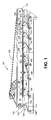
- FIG. 1 illustrates a schematic side view of the apparatus 100
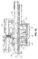
- FIG. 1A illustrates a plan view of the apparatus 100
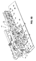
- FIG. 1 B illustrates a perspective view of the apparatus 100.
- Apparatus 100 may comprise a belt drive mechanism 101, a registration wall 102, a weighing device 103, a plurality of inboard skis 104, a plurality of first pins 109, a plurality of inboard rollers 112, a plurality of second pins 110, a plurality of outboard rollers 111, and a plurality of outboard skis 105.
- the registration wall 102 may be fixably mounted to a housing (not shown) and may extend generally perpendicular relative to the weighing device 103 and parallel to a path of travel.
- the belt drive mechanism 101 may be located at a first distance from the registration wall.
- the belt drive mechanism 101 may comprise a belt 108, a first pulley 106 and a second pulley 107. At least one of the first pulley 106 and the second pulley 107 may be powered by a motor.
- the belt 108 may be approximately one and fifteen hundredths of an inch wide.
- the drive belt 108 may be approximately two and three quarter inches from the registration wall 102 and in some embodiments, the drive belt may be approximately one and three quarter inches from the registration wall 102.
- the registration wall 102 may align a mail piece on the path of travel as the belt drive mechanism 101 couples the mail piece via the belt 108 and drives the mail piece in a drive direction. As illustrated, the drive direction of the belt drive mechanism 101 may be counter clockwise. The registration wall 102 may extend across the weighing device 103 for advancing a mail piece relative to the weighing device 103.
- the drive belt mechanism 101 may stop advancing the mail piece when the mail piece is over the weighing device 103 so the weighing device 103 may weigh the mail piece as it travels on the path of travel.
- the weighing device 103 may comprise a load cell not separately shown and may be located adjacent to the registration wall 102.
- the plurality of inboard skis 104 may be located substantially at the first distance from the registration wall and may be located beneath the belt drive mechanism 101 for urging the mail piece 115 upwardly toward the drive belt mechanism 101.
- a top surface of the mail piece 115 may be held against the belt 108 by the inboard plurality of skis 104 that push up against the bottom surface of the mail piece 115 with the top surface of the mail piece 115 held against the belt 108, the belt 108 is able to apply a drive force necessary to move the mail piece 115.
- the plurality of outboard skis 105 may be coplanar with the plurality of inboard skis 104 for supporting an end of the mail piece.
- the plurality of outboard skis 105 may be located at a second distance from the registration wall 102 and as illustrated, the second distance is greater than the first distance.
- the plurality of outboard skis 105 may also be inclined upwardly and towards a drive direction of the belt drive mechanism 101.
- the plurality of inboard skis 104 may be pivotally coupled to the weighing device and the plurality of outboard skis 105 may be pivotally coupled to the weighing device. Pivotally coupling each ski 104/105 may allow the plurality of inboard skis 104 and the plurality of outboard skis 105 to adjust to a thickness of a mail piece that is moved between the inboard skis 104 and the drive belt mechanism 101. The plurality of outboard skis 105 may also adjust to the thickness of the mail piece in response to the inboard skis 104 adjusting. As illustrated, the plurality of inboard skis 104 is inclined upwardly and towards a drive direction of the belt drive mechanism 101.
- each ski of the plurality of inboard skis 104 may comprise a spring 113, and each ski of the plurality of outboard skis 105 may not comprise a spring. In some embodiments, the plurality of inboard skis 104 comprise a greater number than the plurality of outboard skis 105. In some embodiments, the drive mechanism 101, registration wall 102, inboard skis 104 and outboard skis 105, first pins 109 and second pins 110, and inboard rollers 112 and outboard rollers 111 are coupled to a weighing device 103.
- Each of the plurality of outboard skis 105 is coupled to a respective one of the plurality of inboard skis 104 via one of the plurality of first pins 109 and via one of the plurality of second pins 110.
- the first pin 109 may couple a bottom portion of a respective one of the plurality of outboard skis 105 to a bottom portion of a respective one of the plurality of inboard skis 104.
- Each second pin 110 may couple a top portion of a respective one of the plurality of outboard skis 105 to a top portion of a respective one of the plurality of inboard skis 104.
- the first pin may be a pivot shaft and the second pin may be a roller shaft.
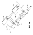
- FIG. 2 and FIG. 2A an embodiment of an inboard ski 201 (that is similar to ski 104) and an embodiment of an outboard ski 202 (that is similar to ski 105) are illustrated.
- FIG. 2 illustrates a top view of the inboard ski 201 and the outboard ski 202
- FIG. 2A illustrates a perspective view of the inboard ski 201 and the outboard ski 202.
- the inboard ski 201 may comprise a inboard arm 203, an inboard roller 205, and a spring 212.
- the outboard ski 202 may comprise an outboard arm 204, and an outboard roller 206.
- the inboard arm 203 may be coupled to the outboard arm 204 by a first pin 209 and a second pin 207.
- the inboard arm 204 may be coupled to the inboard roller 205 via the second pin 207.
- the second pin 207 may also couple the outboard arm 204 to the outboard roller 206.
- the second pin 207 may run lengthwise through a center of the inboard roller 205 and may run lengthwise through a center of the outboard roller 206.
- the spring 212 may be coupled to the inboard arm 203 to allow the inboard arm 203 to pivot in a drive direction of the drive belt mechanism 101.
- the spring may be coupled to the inboard arm 203 and the first pin 209.
- the inboard roller 205 may be cylindrically shaped and the outboard roller 206 may be cylindrically shaped.
- the inboard roller 205 may have a same radius as the outboard roller 206.
- the inboard roller 205 and the outboard roller 206 may be comprised of rubber.
- the inboard roller 205 and the outboard roller 206 may be comprised of urethane.
- the inboard roller 205 and the outboard roller 206 rotate about the second pin 207.
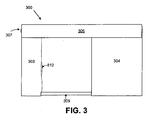
- the multi-arm ski 300 may comprise a first arm 303 (that is similar to ski 104) and a second arm 304 (that is similar to ski 105).
- the first arm 303 and the second arm 304 may be coupled by a first pin 309 and a second pin 307.
- a roller 305 may be coupled between the first arm 303 and the second arm 304 and may be coupled to the first arm 303 and the second arm 304 by the second pin 307.
- the second pin 307 may run lengthwise through a center of the roller 305.
- the roller 305 may extend to a distance from a registration wall of at least three and one half inches beyond a belt drive mechanism, such as that described with respect to FIG. 1 .
- the roller may contact the mail piece to urge a mail piece upwardly toward the belt drive mechanism.
- the ski mechanism may decrease an amount of flutter experienced by the mail piece as it is weighted.
- the spring 312 may be coupled to the first arm 303 and the first pin 309 to allow the first arm 303 to pivot in a drive direction of the drive belt mechanism 101.
- the first arm 303 and the second arm 304 may be replaced by a transport arm that is wider than the first arm 303 and the second arm 304.
- the single-arm ski 400 (that combines skis 104 and 105) may comprise an arm 403 coupled to a housing by a first pin 409.
- a roller 405 may be coupled to a top portion of the arm 403 by a second pin 407 that runs lengthwise through a center of the roller 405.
- the roller 405 may extend to a distance from a registration wall of at least three and one half inches beyond a belt drive mechanism, such as that described with respect to FIG. 1 .
- the roller 405 may contact the mail piece to urge a mail piece upwardly toward the belt drive mechanism.
- the ski mechanism may decrease an amount of flutter experienced by the mail piece as it is weighted.
- the spring 412 may be coupled to the arm 403 and the first pin 409 to allow the arm 403 to pivot in a drive direction of the drive belt mechanism 101.
- the inboard ski 501 may comprise a inboard arm 503, an inboard roller 505, and a spring 512.
- the outboard ski 502 may comprise an outboard arm 504, and an outboard roller 506.
- the inboard arm 503 (that is similar to ski 104) may be coupled to the outboard arm 504 (that is similar to ski 105) by a first pin 509 and a second pin 507.
- the inboard arm 504 may be coupled to the inboard roller 505 via the second pin 507.
- the second pin 507 may also couple the outboard arm 504 to the outboard roller 506.
- the second pin 507 may run lengthwise through a center of the inboard roller 505 and may run lengthwise through a center of the outboard roller 506.
- the spring 512 may be coupled to the inboard arm 503 to allow the inboard arm 503 to pivot in a drive direction of the drive belt mechanism 101.
- the spring may be coupled to the inboard arm 503 and the first pin 509.
- the inboard roller 505 may be cylindrically shaped and the outboard roller 506 may be cylindrically shaped.
- the outboard roller 506 may be wider than the inboard roller 505 and the outboard arm 504 may be wider than the inboard arm 503.
- the inboard roller 505 may have a same radius as the outboard roller 506.
- the inboard roller 505 and the outboard roller 506 may be comprised of rubber.
- the inboard roller 505 and the outboard roller 506 may be comprised of urethane.
- the inboard roller 505 and the outboard roller 506 rotate about the second pin 507.
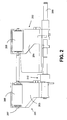
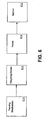
- Fig. 6 discloses a system 600 according to some embodiments.
- the system 600 may comprise a feeder 611, a stacker 612, a printer 614, and an apparatus 613, such as that described with respect to FIG. 1 , FIG. 1A , and FIG 1B .
- the apparatus 613 may comprise a belt drive mechanism that includes a belt, a registration wall, a weighing device, a plurality of inboard skis, a plurality of first pins, a plurality of second pins, and a plurality of outboard skis as described with respect to similarly named elements of apparatus 100.
- the feeder 611 may insert a plurality of mail pieces, one at a time, into the apparatus 613 to be weighed. Once weighed, the apparatus may move each mail piece to the printer 614 where appropriate indicia is printed on the mail piece. The mail piece is then transported to a stacker 612 that receives each mail piece and then stacks the plurality of mail pieces.
- the system may further comprise a moistener to moisten a flap of the mail piece and a sealer to seal the flap of the mail piece.
Landscapes
- Physics & Mathematics (AREA)
- Engineering & Computer Science (AREA)
- Mathematical Physics (AREA)
- Theoretical Computer Science (AREA)
- General Physics & Mathematics (AREA)
- Mechanical Engineering (AREA)
- Devices For Checking Fares Or Tickets At Control Points (AREA)
- Sorting Of Articles (AREA)
- Sheets, Magazines, And Separation Thereof (AREA)
Abstract
Description
- A mailing machine, such as a Pitney Bowes DM1000, may automatically feed a mail piece, seal a flap of the mail piece, imprint postage on the mail piece and stack uniform mail pieces at speeds of up to 260 letters per minute. The mailing machine may handle mail pieces ranging in size from post cards to 10 inch x 13 inch flats and up to ¾ inch thick, intermixed and in a single stream. Intermixing sizes may reduce a need to sort mail by size.
- Some mail machines may comprise an in-line weighing mechanism, such as the Pitney Bowes Weigh-on-the-Way™ ("WOW") mechanism. The in-line weighing mechanism may weigh each mail piece to ensure that proper postage indicia will be applied. When a mail piece arrives at the in-line weighing mechanism, a weighing signal may indicate that an accurate measurement has been taken and that the mail piece may be advanced for printing of postage indicia. This significantly reduces the time it takes to obtain an accurate weight of the mail piece.
- When weighing flats, or mail pieces large enough that a portion of the mail piece is unsupported, the unsupported portions may flutter (i.e. an oscillating motion). This flutter may increase an amount of time required for the weighing signal to indicate that the mail piece has been accurately weighed.
- Generally, a system and an apparatus comprise a registration wall, a weighing device located adjacent to the registration wall, a belt drive mechanism, a plurality of inboard skis, and a plurality of outboard skis. The belt drive mechanism extends across the weighing device for advancing a mail piece relative to the weighing device and the belt drive mechanism is located at a first distance from the registration wall. The plurality of inboard skis are located substantially at the first distance from the registration wall and are located beneath the belt drive mechanism for urging the mail piece upwardly toward the drive belt mechanism. The plurality of outboard skis is coplanar with the plurality of inboard skis for supporting an end of the mail piece. The plurality of outboard skis is located at a second distance from the registration wall. The second distance is greater than the first distance.
- Therefore, it should now be apparent that the invention substantially achieves all the above aspects and advantages. Additional aspects and advantages of the invention will be set forth in the description that follows, and in part will be obvious from the description, or may be learned by practice of the invention. Various features and embodiments are further described in the following figures, descriptions, and claims.
- The accompanying drawings illustrate presently preferred embodiments of the invention, and together with the general description given above and the detailed description given below, serve to explain the principles of the invention. As shown throughout the drawings, like reference numerals designate like or corresponding parts.
-
FIG. 1 illustrates a schematic side view of an apparatus according to some embodiments. -
FIG. 1A illustrates a plan view of an apparatus according to some embodiments. -
FIG. 1 B illustrates a perspective view of an apparatus according to some embodiments. -
FIG. 2 illustrates an inboard ski and an outboard ski according to some embodiments. -
FIG. 2A illustrates a perspective view of an inboard ski and an outboard ski according to some embodiments. -
FIG. 3 illustrates a multi-arm ski according to some embodiments. -
FIG. 4 illustrates a single-arm ski according to some embodiments. -
FIG. 5 illustrates an inboard ski and an outboard ski according to some embodiments. -
FIG. 6 illustrates a system according to some embodiments. - The several embodiments described herein are provided solely for the purpose of illustration. Embodiments may include any currently or hereafter-known versions of the elements described herein. Therefore, persons in the art will recognize from this description that other embodiments may be practiced with various modifications and alterations.
- Currently, stationary WOW transport rails only provide support for very thick mail pieces because the transport rails are located well below the surface of a transport belt to allow for the transport of a thickest allowable mail pieces without creating a binding condition between the stationary rails and the belt. The following provides outboard support for flats, regardless of thickness, by eliminating the stationary rails and extending the WOW transport skis outboard which may improve stabilization of the flat during a weighing process which in turn may significantly reduces the time it takes to obtain an accurate weight.
- Now referring to
FIG. 1 ,FIG. 1A , andFIG. 1B , an embodiment of an apparatus 100 is illustrated. In some embodiments,FIG. 1 illustrates a schematic side view of the apparatus 100,FIG. 1A illustrates a plan view of the apparatus 100, andFIG. 1 B illustrates a perspective view of the apparatus 100. Apparatus 100 may comprise abelt drive mechanism 101, aregistration wall 102, aweighing device 103, a plurality ofinboard skis 104, a plurality offirst pins 109, a plurality ofinboard rollers 112, a plurality ofsecond pins 110, a plurality ofoutboard rollers 111, and a plurality ofoutboard skis 105. - The
registration wall 102, as illustrated inFIG. 1A , may be fixably mounted to a housing (not shown) and may extend generally perpendicular relative to theweighing device 103 and parallel to a path of travel. Thebelt drive mechanism 101 may be located at a first distance from the registration wall. Thebelt drive mechanism 101 may comprise abelt 108, afirst pulley 106 and asecond pulley 107. At least one of thefirst pulley 106 and thesecond pulley 107 may be powered by a motor. In some embodiments, thebelt 108 may be approximately one and fifteen hundredths of an inch wide. In some embodiments, thedrive belt 108 may be approximately two and three quarter inches from theregistration wall 102 and in some embodiments, the drive belt may be approximately one and three quarter inches from theregistration wall 102. - The
registration wall 102 may align a mail piece on the path of travel as thebelt drive mechanism 101 couples the mail piece via thebelt 108 and drives the mail piece in a drive direction. As illustrated, the drive direction of thebelt drive mechanism 101 may be counter clockwise. Theregistration wall 102 may extend across theweighing device 103 for advancing a mail piece relative to theweighing device 103. - The
drive belt mechanism 101 may stop advancing the mail piece when the mail piece is over theweighing device 103 so theweighing device 103 may weigh the mail piece as it travels on the path of travel. Theweighing device 103 may comprise a load cell not separately shown and may be located adjacent to theregistration wall 102. - The plurality of
inboard skis 104 may be located substantially at the first distance from the registration wall and may be located beneath thebelt drive mechanism 101 for urging themail piece 115 upwardly toward thedrive belt mechanism 101. In other words, a top surface of themail piece 115 may be held against thebelt 108 by the inboard plurality ofskis 104 that push up against the bottom surface of themail piece 115 with the top surface of themail piece 115 held against thebelt 108, thebelt 108 is able to apply a drive force necessary to move themail piece 115. - The plurality of
outboard skis 105 may be coplanar with the plurality ofinboard skis 104 for supporting an end of the mail piece. The plurality ofoutboard skis 105 may be located at a second distance from theregistration wall 102 and as illustrated, the second distance is greater than the first distance. As illustrated, the plurality ofoutboard skis 105 may also be inclined upwardly and towards a drive direction of thebelt drive mechanism 101. - The plurality of
inboard skis 104 may be pivotally coupled to the weighing device and the plurality ofoutboard skis 105 may be pivotally coupled to the weighing device. Pivotally coupling eachski 104/105 may allow the plurality ofinboard skis 104 and the plurality ofoutboard skis 105 to adjust to a thickness of a mail piece that is moved between theinboard skis 104 and thedrive belt mechanism 101. The plurality ofoutboard skis 105 may also adjust to the thickness of the mail piece in response to theinboard skis 104 adjusting. As illustrated, the plurality ofinboard skis 104 is inclined upwardly and towards a drive direction of thebelt drive mechanism 101. In some embodiments, each ski of the plurality ofinboard skis 104 may comprise aspring 113, and each ski of the plurality ofoutboard skis 105 may not comprise a spring. In some embodiments, the plurality ofinboard skis 104 comprise a greater number than the plurality ofoutboard skis 105. In some embodiments, thedrive mechanism 101,registration wall 102,inboard skis 104 andoutboard skis 105,first pins 109 andsecond pins 110, andinboard rollers 112 andoutboard rollers 111 are coupled to a weighingdevice 103. - Each of the plurality of
outboard skis 105 is coupled to a respective one of the plurality ofinboard skis 104 via one of the plurality offirst pins 109 and via one of the plurality of second pins 110. Thefirst pin 109 may couple a bottom portion of a respective one of the plurality ofoutboard skis 105 to a bottom portion of a respective one of the plurality ofinboard skis 104. Eachsecond pin 110 may couple a top portion of a respective one of the plurality ofoutboard skis 105 to a top portion of a respective one of the plurality ofinboard skis 104. In some embodiments, the first pin may be a pivot shaft and the second pin may be a roller shaft. - Now referring to
FIG. 2 andFIG. 2A , an embodiment of an inboard ski 201 (that is similar to ski 104) and an embodiment of an outboard ski 202 (that is similar to ski 105) are illustrated. In some embodiments,FIG. 2 illustrates a top view of theinboard ski 201 and theoutboard ski 202 andFIG. 2A illustrates a perspective view of theinboard ski 201 and theoutboard ski 202. Theinboard ski 201 may comprise ainboard arm 203, aninboard roller 205, and aspring 212. Theoutboard ski 202 may comprise anoutboard arm 204, and anoutboard roller 206. - The
inboard arm 203 may be coupled to theoutboard arm 204 by afirst pin 209 and asecond pin 207. Theinboard arm 204 may be coupled to theinboard roller 205 via thesecond pin 207. Thesecond pin 207 may also couple theoutboard arm 204 to theoutboard roller 206. Thesecond pin 207 may run lengthwise through a center of theinboard roller 205 and may run lengthwise through a center of theoutboard roller 206. - The
spring 212 may be coupled to theinboard arm 203 to allow theinboard arm 203 to pivot in a drive direction of thedrive belt mechanism 101. In some embodiments, the spring may be coupled to theinboard arm 203 and thefirst pin 209. - The
inboard roller 205 may be cylindrically shaped and theoutboard roller 206 may be cylindrically shaped. Theinboard roller 205 may have a same radius as theoutboard roller 206. In some embodiments theinboard roller 205 and theoutboard roller 206 may be comprised of rubber. In some embodiments, theinboard roller 205 and theoutboard roller 206 may be comprised of urethane. In some embodiments, theinboard roller 205 and theoutboard roller 206 rotate about thesecond pin 207. - Now referring to
FIG. 3 , amulti-arm ski 300 is illustrated according to some embodiments. Themulti-arm ski 300 may comprise a first arm 303 (that is similar to ski 104) and a second arm 304 (that is similar to ski 105). Thefirst arm 303 and thesecond arm 304 may be coupled by afirst pin 309 and asecond pin 307. Aroller 305 may be coupled between thefirst arm 303 and thesecond arm 304 and may be coupled to thefirst arm 303 and thesecond arm 304 by thesecond pin 307. Thesecond pin 307 may run lengthwise through a center of theroller 305. - The
roller 305 may extend to a distance from a registration wall of at least three and one half inches beyond a belt drive mechanism, such as that described with respect toFIG. 1 . The roller may contact the mail piece to urge a mail piece upwardly toward the belt drive mechanism. By contacting the mail piece at least three and one half inches beyond a belt drive mechanism, the ski mechanism may decrease an amount of flutter experienced by the mail piece as it is weighted. - The
spring 312 may be coupled to thefirst arm 303 and thefirst pin 309 to allow thefirst arm 303 to pivot in a drive direction of thedrive belt mechanism 101. In some embodiments, thefirst arm 303 and thesecond arm 304 may be replaced by a transport arm that is wider than thefirst arm 303 and thesecond arm 304. - Now referring to
FIG. 4 , a single-arm ski 400 is illustrated according to some embodiments. The single-arm ski 400 (that combinesskis 104 and 105) may comprise anarm 403 coupled to a housing by afirst pin 409. Aroller 405 may be coupled to a top portion of thearm 403 by asecond pin 407 that runs lengthwise through a center of theroller 405. - The
roller 405 may extend to a distance from a registration wall of at least three and one half inches beyond a belt drive mechanism, such as that described with respect toFIG. 1 . Theroller 405 may contact the mail piece to urge a mail piece upwardly toward the belt drive mechanism. By contacting the mail piece at least three and one half inches beyond a belt drive mechanism, the ski mechanism may decrease an amount of flutter experienced by the mail piece as it is weighted. - The
spring 412 may be coupled to thearm 403 and thefirst pin 409 to allow thearm 403 to pivot in a drive direction of thedrive belt mechanism 101. - Now referring to
FIG. 5 , an embodiment of aninboard ski 501 and an embodiment of anoutboard ski 502 are illustrated. Theinboard ski 501 may comprise ainboard arm 503, aninboard roller 505, and aspring 512. Theoutboard ski 502 may comprise anoutboard arm 504, and anoutboard roller 506. - The inboard arm 503 (that is similar to ski 104) may be coupled to the outboard arm 504 (that is similar to ski 105) by a
first pin 509 and asecond pin 507. Theinboard arm 504 may be coupled to theinboard roller 505 via thesecond pin 507. Thesecond pin 507 may also couple theoutboard arm 504 to theoutboard roller 506. Thesecond pin 507 may run lengthwise through a center of theinboard roller 505 and may run lengthwise through a center of theoutboard roller 506. - The
spring 512 may be coupled to theinboard arm 503 to allow theinboard arm 503 to pivot in a drive direction of thedrive belt mechanism 101. In some embodiments, the spring may be coupled to theinboard arm 503 and thefirst pin 509. - The
inboard roller 505 may be cylindrically shaped and theoutboard roller 506 may be cylindrically shaped. Theoutboard roller 506 may be wider than theinboard roller 505 and theoutboard arm 504 may be wider than theinboard arm 503. Theinboard roller 505 may have a same radius as theoutboard roller 506. In some embodiments theinboard roller 505 and theoutboard roller 506 may be comprised of rubber. In some embodiments, theinboard roller 505 and theoutboard roller 506 may be comprised of urethane. In some embodiments, theinboard roller 505 and theoutboard roller 506 rotate about thesecond pin 507. -
Fig. 6 discloses a system 600 according to some embodiments. The system 600 may comprise afeeder 611, astacker 612, aprinter 614, and anapparatus 613, such as that described with respect toFIG. 1 ,FIG. 1A , andFIG 1B . Theapparatus 613 may comprise a belt drive mechanism that includes a belt, a registration wall, a weighing device, a plurality of inboard skis, a plurality of first pins, a plurality of second pins, and a plurality of outboard skis as described with respect to similarly named elements of apparatus 100. - The
feeder 611 may insert a plurality of mail pieces, one at a time, into theapparatus 613 to be weighed. Once weighed, the apparatus may move each mail piece to theprinter 614 where appropriate indicia is printed on the mail piece. The mail piece is then transported to astacker 612 that receives each mail piece and then stacks the plurality of mail pieces. The system may further comprise a moistener to moisten a flap of the mail piece and a sealer to seal the flap of the mail piece. - A number of embodiments of the present invention have been described. Nevertheless, it will be understood that various modifications may be made without departing from the scope of the invention. Other variations relating to implementation of the functions described herein can also be implemented. Accordingly, other embodiments are within the scope of the following claims.
Claims (13)
- An apparatus comprising:a registration wall (102);a weighing device (103) located adjacent to the registration wall (102);a belt drive mechanism (101) extending across the weighing device (103) for advancing a mail piece relative to the weighing device (103), wherein the belt drive mechanism (101) is located at a first distance from the registration wall (102);a plurality of inboard skis (104; 201) located substantially at the first distance from the registration wall (102) and located beneath the belt drive mechanism (101) for urging the mail piece upwardly toward the drive belt mechanism (101); anda plurality of outboard skis (105; 202), coplanar with the plurality of inboard skis (104; 201) for supporting an end of the mail piece, wherein the plurality of outboard skis (105; 202) is located at a second distance from the registration wall (102), and wherein the second distance is greater than the first distance.
- The apparatus of Claim 1, wherein the plurality of inboard skis (104; 201) are pivotally coupled to the weighing device (103), wherein the plurality of outboard skis (105; 202) are pivotally coupled to the weighing device (103), and wherein each ski of the plurality of inboard skis (104; 201) comprises a spring (113), and each ski of the plurality of outboard skis (105; 202) does not comprise a spring.
- The apparatus of Claim 1 or 2, wherein the plurality of inboard skis (104; 201) are inclined upwardly and towards a drive direction of the belt drive mechanism (101).
- The apparatus of Claim 1, 2 or 3, wherein the plurality of inboard skis (104; 201) adjust to a thickness of a mail piece that is moved between the inboard skis (104; 201) and the belt drive mechanism (101), and wherein the plurality of outboard skis (105; 202) adjust to the thickness of the mail piece in response to the adjustment of the inboard skis (104; 201).
- The apparatus of any preceding claim, wherein each of the plurality of inboard skis comprises a first arm (203; 303) and a first roller (205; 305), wherein each of the plurality of outboard skis comprises a second arm (204; 304) and a second roller (206), and wherein the second arm is wider than the first arm.
- The apparatus of any preceding claim, wherein each of the plurality of outboard skis (105, 202) is coupled to a respective one of the plurality of inboard skis (104, 201) via a first pin (109, 209, 309, 409, 509) and via a second pin (110, 207, 307, 407, 507), wherein the first pin couples a bottom portion of a respective one of the plurality of outboard skis (105, 202) to a bottom portion of a respective one of the plurality of inboard skis (104, 201), and wherein the second pin couples a top portion of a respective one of the plurality of outboard skis to a top portion of a respective one of the plurality of inboard skis.
- The apparatus of Claim 5 and 6, wherein the first roller (205, 305, 405, 505) is cylindrically shaped and the second roller (206, 506) is cylindrically shaped, and wherein the second pin runs lengthwise through a center of the first roller and runs lengthwise through a center of the second roller.
- The apparatus of any preceding claim, wherein the plurality of inboard skis comprise a greater number than the plurality of outboard skis.
- A apparatus comprising:a registration wall (102);a weighing device (103) located adjacent to the registration wall (102);a belt drive mechanism (101) extending across the weighing device (103) for advancing a mail piece relative to the weighing device (103), wherein the belt drive mechanism (101) is located at a first distance from the registration wall (102);a plurality of ski arms (203, 204; 303, 304; 403; 503, 504) located substantially at the first distance from the registration wall (102) and located beneath the belt drive mechanism (101); anda plurality of rollers (111, 112; 205, 206; 305; 405; 505, 506), each roller coupled to a top portion of a respective one of the plurality of ski arms, each roller extending to a distance from said registration wall of at least three and one half inches beyond said first distance, said rollers for contacting the mail piece to urge said mail piece upwardly toward said belt drive mechanism (101).
- The weighing device of Claim 9, wherein the plurality of ski arms are pivotally coupled to the weighing device (103).
- The weighing device of Claim 9 or 10, wherein the plurality of ski arms are inclined upwardly and towards a drive direction of the belt drive mechanism (101).
- The weighing device of Claim 9, 10 or 11, wherein the plurality of ski arms adjust to a thickness of a mail piece that is moved between the inboard skis and the drive belt mechanism (101), and wherein the plurality of outboard skis adjust to the thickness of the mail piece in response to the adjustment of the inboard skis.
- The apparatus of any one of Claims 9 to 12, wherein each of the plurality of inboard skis comprises a first arm and each of the plurality of outboard skis comprises a second arm, and wherein the second arm is wider than the first arm.
Applications Claiming Priority (1)
| Application Number | Priority Date | Filing Date | Title |
|---|---|---|---|
| US11/957,129 US7750254B2 (en) | 2007-12-14 | 2007-12-14 | Self-adjusting support skis for weighing device |
Publications (1)
| Publication Number | Publication Date |
|---|---|
| EP2071303A1 true EP2071303A1 (en) | 2009-06-17 |
Family
ID=40547432
Family Applications (1)
| Application Number | Title | Priority Date | Filing Date |
|---|---|---|---|
| EP08021228A Withdrawn EP2071303A1 (en) | 2007-12-14 | 2008-12-05 | Self-adjusting support skis for weighing device |
Country Status (2)
| Country | Link |
|---|---|
| US (1) | US7750254B2 (en) |
| EP (1) | EP2071303A1 (en) |
Cited By (1)
| Publication number | Priority date | Publication date | Assignee | Title |
|---|---|---|---|---|
| US7900915B2 (en) | 2007-11-28 | 2011-03-08 | Wipotec Wiege-Und Positioniersysteme Gmbh | Device for transporting and weighing letters |
Families Citing this family (2)
| Publication number | Priority date | Publication date | Assignee | Title |
|---|---|---|---|---|
| US8178796B2 (en) * | 2009-12-17 | 2012-05-15 | Pitney Bowes Inc. | Mailing machine transport system including a guide to reduce the impact on the weighing device caused by the trailing edge of the mailpeice |
| US8148650B2 (en) * | 2009-12-17 | 2012-04-03 | Pitney Bowes Inc. | Mailing machine transport system with integral scale for weighing mail pieces where the contact force on the take away rollers is reduced to eliminate oscillations of the weighing platform |
Citations (6)
| Publication number | Priority date | Publication date | Assignee | Title |
|---|---|---|---|---|
| EP1096239A1 (en) * | 1999-10-25 | 2001-05-02 | Neopost Industrie | Dynamic weighing module with a device for holding and guiding postal items |
| EP1362644A1 (en) * | 2002-05-17 | 2003-11-19 | Bell & Howell Postal Systems, Inc. | In-line mail weighing system and scale |
| EP1431925A2 (en) * | 2002-12-19 | 2004-06-23 | Pitney Bowes Inc. | Transport mechanism for a mailing machine and method to register a mail piece in a mailing machine |
| US20040178566A1 (en) * | 2003-03-06 | 2004-09-16 | Pitney Bowes Incorporated | Transport mechanism for a mailing machine |
| US20060220294A1 (en) | 2005-03-21 | 2006-10-05 | Pitney Bowes Incorporated | Jam release mechanism for a mailing machine |
| EP2017589A2 (en) * | 2007-07-02 | 2009-01-21 | Pitney Bowes, Inc. | Device for weighing mail pieces |
Family Cites Families (13)
| Publication number | Priority date | Publication date | Assignee | Title |
|---|---|---|---|---|
| US2841270A (en) * | 1956-03-21 | 1958-07-01 | Int Paper Box Machine Co | Individual presser roll unit |
| US3951257A (en) * | 1974-10-30 | 1976-04-20 | Pitney-Bowes, Inc. | Mail transporting mechanism |
| US4742878A (en) * | 1986-09-19 | 1988-05-10 | Pitney Bowes Inc. | Weighing module |
| US4778018A (en) | 1987-07-13 | 1988-10-18 | Pitney Bowes Inc. | Apparatus and method of determining the mass of an article by measuring the shift in the period of harmonic motion |
| US4856604A (en) | 1988-04-01 | 1989-08-15 | Pitney Bowes Inc. | Apparatus and method of determining the authenticity of weight obtained from a vibrating tray scale |
| US4836313A (en) | 1989-01-09 | 1989-06-06 | Pitney Bowes Inc. | Oscillating and locking apparatus and method for vibrating tray weighing scale |
| US5190115A (en) * | 1990-08-30 | 1993-03-02 | Pitney Bowes Inc. | Modular mailing machine with load cell scale |
| US5726393A (en) | 1994-07-08 | 1998-03-10 | Pitney Bowes Inc. | Fixed transport assembly for mail weighing scale |
| US6940025B1 (en) * | 1994-12-27 | 2005-09-06 | Pitney Bowes Inc. | Method and apparatus for determining the mass of an article using a load cell |
| US5723825A (en) | 1996-04-01 | 1998-03-03 | Pitney Bowes Inc. | Transport apparatus for a weighing module |
| US5890714A (en) * | 1997-01-21 | 1999-04-06 | Xerox Corporation | Accessible copy sheet transport with side guides |
| US6024429A (en) * | 1997-10-30 | 2000-02-15 | Pitney Bowes Inc. | Mailing machine including ink jet printing having ink availability checking |
| FR2881550B1 (en) * | 2005-01-31 | 2007-05-11 | Neopost Ind Sa | MECHANICAL DEVICE FOR MEASURING THE WIDTH OF A MAIL ARTICLE |
-
2007
- 2007-12-14 US US11/957,129 patent/US7750254B2/en not_active Expired - Fee Related
-
2008
- 2008-12-05 EP EP08021228A patent/EP2071303A1/en not_active Withdrawn
Patent Citations (6)
| Publication number | Priority date | Publication date | Assignee | Title |
|---|---|---|---|---|
| EP1096239A1 (en) * | 1999-10-25 | 2001-05-02 | Neopost Industrie | Dynamic weighing module with a device for holding and guiding postal items |
| EP1362644A1 (en) * | 2002-05-17 | 2003-11-19 | Bell & Howell Postal Systems, Inc. | In-line mail weighing system and scale |
| EP1431925A2 (en) * | 2002-12-19 | 2004-06-23 | Pitney Bowes Inc. | Transport mechanism for a mailing machine and method to register a mail piece in a mailing machine |
| US20040178566A1 (en) * | 2003-03-06 | 2004-09-16 | Pitney Bowes Incorporated | Transport mechanism for a mailing machine |
| US20060220294A1 (en) | 2005-03-21 | 2006-10-05 | Pitney Bowes Incorporated | Jam release mechanism for a mailing machine |
| EP2017589A2 (en) * | 2007-07-02 | 2009-01-21 | Pitney Bowes, Inc. | Device for weighing mail pieces |
Cited By (1)
| Publication number | Priority date | Publication date | Assignee | Title |
|---|---|---|---|---|
| US7900915B2 (en) | 2007-11-28 | 2011-03-08 | Wipotec Wiege-Und Positioniersysteme Gmbh | Device for transporting and weighing letters |
Also Published As
| Publication number | Publication date |
|---|---|
| US7750254B2 (en) | 2010-07-06 |
| US20090152020A1 (en) | 2009-06-18 |
Similar Documents
| Publication | Publication Date | Title |
|---|---|---|
| US8148650B2 (en) | Mailing machine transport system with integral scale for weighing mail pieces where the contact force on the take away rollers is reduced to eliminate oscillations of the weighing platform | |
| US4763575A (en) | Envelope pressure plate for mailing machine | |
| US7168700B2 (en) | Sheet feeder apparatus and method with throughput control | |
| US8178796B2 (en) | Mailing machine transport system including a guide to reduce the impact on the weighing device caused by the trailing edge of the mailpeice | |
| GB2197852A (en) | Improved deskewing device for mailing machine | |
| US10668504B2 (en) | Item individualization station | |
| US20040178566A1 (en) | Transport mechanism for a mailing machine | |
| US6817608B2 (en) | Method and apparatus for stacking mailpieces in consecutive order | |
| US5575465A (en) | Apparatus for transporting documents conveyed from two directions | |
| US6942214B2 (en) | Mail registration and feeding apparatus | |
| US7750254B2 (en) | Self-adjusting support skis for weighing device | |
| GB2285040A (en) | Changing the direction of motion of documents. | |
| US5726393A (en) | Fixed transport assembly for mail weighing scale | |
| US6793215B2 (en) | Self-adjusting side guide for a mail handling device | |
| US4615519A (en) | Mail separating device | |
| EP1431925B1 (en) | Transport mechanism for a mailing machine and method to register a mail piece in a mailing machine | |
| US7416183B2 (en) | Postal weighing platform with integrated feeding and deskewing functions | |
| US4957179A (en) | Tape module for a modular mailing machine | |
| US20040080103A1 (en) | Jam release mechanism for a mailing machine | |
| US4865139A (en) | Inker module for a modular mailing machine | |
| CA2074868C (en) | Clamping arm for envelope turner | |
| US5538239A (en) | Right angle transfer apparatus with enabling and disabling means | |
| CA1319902C (en) | Mailing machine | |
| GB2258458A (en) | Method and apparatus for aligning while changing direction of flat articles | |
| CA2054515C (en) | Method and apparatus for changing the direction of motion of flat articles |
Legal Events
| Date | Code | Title | Description |
|---|---|---|---|
| PUAI | Public reference made under article 153(3) epc to a published international application that has entered the european phase |
Free format text: ORIGINAL CODE: 0009012 |
|
| AK | Designated contracting states |
Kind code of ref document: A1 Designated state(s): AT BE BG CH CY CZ DE DK EE ES FI FR GB GR HR HU IE IS IT LI LT LU LV MC MT NL NO PL PT RO SE SI SK TR |
|
| AX | Request for extension of the european patent |
Extension state: AL BA MK RS |
|
| 17P | Request for examination filed |
Effective date: 20091210 |
|
| AKX | Designation fees paid |
Designated state(s): CH DE FR GB LI |
|
| 17Q | First examination report despatched |
Effective date: 20100409 |
|
| STAA | Information on the status of an ep patent application or granted ep patent |
Free format text: STATUS: THE APPLICATION IS DEEMED TO BE WITHDRAWN |
|
| 18D | Application deemed to be withdrawn |
Effective date: 20100820 |