EP2071252A1 - Air conditioner - Google Patents
Air conditioner Download PDFInfo
- Publication number
- EP2071252A1 EP2071252A1 EP07792963A EP07792963A EP2071252A1 EP 2071252 A1 EP2071252 A1 EP 2071252A1 EP 07792963 A EP07792963 A EP 07792963A EP 07792963 A EP07792963 A EP 07792963A EP 2071252 A1 EP2071252 A1 EP 2071252A1
- Authority
- EP
- European Patent Office
- Prior art keywords
- shaft
- front panel
- indoor unit
- main body
- unit main
- Prior art date
- Legal status (The legal status is an assumption and is not a legal conclusion. Google has not performed a legal analysis and makes no representation as to the accuracy of the status listed.)
- Withdrawn
Links
- 230000002093 peripheral effect Effects 0.000 claims abstract description 37
- 238000000034 method Methods 0.000 description 4
- 230000000452 restraining effect Effects 0.000 description 3
- 238000009434 installation Methods 0.000 description 2
- 230000000694 effects Effects 0.000 description 1
- 239000011347 resin Substances 0.000 description 1
- 229920005989 resin Polymers 0.000 description 1
Images



Classifications
-
- F—MECHANICAL ENGINEERING; LIGHTING; HEATING; WEAPONS; BLASTING
- F24—HEATING; RANGES; VENTILATING
- F24F—AIR-CONDITIONING; AIR-HUMIDIFICATION; VENTILATION; USE OF AIR CURRENTS FOR SCREENING
- F24F1/00—Room units for air-conditioning, e.g. separate or self-contained units or units receiving primary air from a central station
-
- F—MECHANICAL ENGINEERING; LIGHTING; HEATING; WEAPONS; BLASTING
- F24—HEATING; RANGES; VENTILATING
- F24F—AIR-CONDITIONING; AIR-HUMIDIFICATION; VENTILATION; USE OF AIR CURRENTS FOR SCREENING
- F24F1/00—Room units for air-conditioning, e.g. separate or self-contained units or units receiving primary air from a central station
- F24F1/0007—Indoor units, e.g. fan coil units
- F24F1/0043—Indoor units, e.g. fan coil units characterised by mounting arrangements
- F24F1/0057—Indoor units, e.g. fan coil units characterised by mounting arrangements mounted in or on a wall
-
- F—MECHANICAL ENGINEERING; LIGHTING; HEATING; WEAPONS; BLASTING
- F24—HEATING; RANGES; VENTILATING
- F24F—AIR-CONDITIONING; AIR-HUMIDIFICATION; VENTILATION; USE OF AIR CURRENTS FOR SCREENING
- F24F13/00—Details common to, or for air-conditioning, air-humidification, ventilation or use of air currents for screening
- F24F13/20—Casings or covers
-
- F—MECHANICAL ENGINEERING; LIGHTING; HEATING; WEAPONS; BLASTING
- F24—HEATING; RANGES; VENTILATING
- F24F—AIR-CONDITIONING; AIR-HUMIDIFICATION; VENTILATION; USE OF AIR CURRENTS FOR SCREENING
- F24F13/00—Details common to, or for air-conditioning, air-humidification, ventilation or use of air currents for screening
- F24F13/08—Air-flow control members, e.g. louvres, grilles, flaps or guide plates
- F24F13/10—Air-flow control members, e.g. louvres, grilles, flaps or guide plates movable, e.g. dampers
- F24F13/14—Air-flow control members, e.g. louvres, grilles, flaps or guide plates movable, e.g. dampers built up of tilting members, e.g. louvre
- F24F13/1486—Air-flow control members, e.g. louvres, grilles, flaps or guide plates movable, e.g. dampers built up of tilting members, e.g. louvre characterised by bearings, pivots or hinges
Definitions
- the present invention relates to an air conditioner and, more particularly, to an air conditioner having a front panel which is to be attached to and removed from the indoor unit main body for conveniences of installation, relocation or the like.
- an arm 66 to be inserted into an indoor unit main body is protrusively provided at an upper portion of the rear face of a front panel (not shown), with a shaft 65 provided on the arm so as to extend horizontally (see, e.g., JP H8-135994 A ).
- a bearing portion 63 for rotatably supporting the shaft 65.
- a round hole 64, a horizontal recess 81 adjoining the round hole 64, and a chamfered portion 82 adjoining the recess 81 are provided in the bearing portion 63.
- a chamfer 91 is formed at such a site as to just confront the recess 81 with the front panel opened to a certain angle with respect to the main body.
- the operator When the front panel is attached to the indoor unit main body, the operator, having the front panel in his/her hand, pushes the front panel horizontally with the shaft 65 of the arm 66 aligned with the chamfered portion 82. By this operation, the shaft 65 of the arm 66 is guided and inserted along the chamfered portion 82 and the recess 81 so as to be fitted into the round hole 64. After that, the front panel is turned around the shaft 65, thereby closed with respect to the indoor unit main body. On the other hand, when the front panel is removed from the indoor unit main body, the operator, holding a lower side portion of the front panel, lifts the front panel while pulling it frontward, and then turns the front panel around the shaft 65 to open the panel.
- the chamfer 91 of the shaft 65 just confronts the recess 81 while the arm 66 is elastically deformed in such a direction that the shaft 65 is horizontally disengaged from the round hole 64 by a protrusion 69.
- pulling the front panel frontward causes the chamfer 91 to ride on the recess 81 while, with the arm 66 elastically deformed, the shaft 65 is moved frontward along the recess 81, so that the front panel is removed from the indoor unit main body.
- a protrusion 68 is for holding the front panel at an angle halfway.
- an object of the present invention to provide an air conditioner which allows the front panel to be easily removed without incurring damage thereon in removal of the front panel from the indoor unit main body.
- an air conditioner comprises an indoor unit main body, and a front panel which is attached to and removed from the indoor unit main body (1), wherein the front panel includes an arm protrusively provided on a rear face so as to be inserted into the indoor unit main body, the arm having a horizontally extending shaft, the indoor unit main body includes a bearing portion serving for rotatably supporting the shaft and having at least a peripheral edge curved so as to be recessed frontward, and a first chamfer is formed at such a site of a tip circumferential portion of the shaft that when the front panel receives an external force in such a direction as to be further opened beyond a fully opened state of a certain opening angle with respect to the indoor unit main body, the first chamfer faces a lower portion of the peripheral edge, so that the first chamfer is brought into contact with the lower portion of the peripheral edge, whereby the arm is elastically deformed in such a direction that the shaft is separated horizontally from the bearing portion.
- the front panel when the front panel is opened from a closed state to a fully opened state of a certain opening angle with respect to the indoor unit main body, the front panel is turned around the shaft while the shaft keeps supported on the bearing portion.
- the first chamfer formed at the tip circumferential portion of the shaft is brought into contact with the lower portion of the peripheral edge, by which the arm is elastically deformed in such a direction that the shaft is disengaged horizontally from the bearing portion. Therefore, in the fully opened state of the front panel, when the worker applies a little excessive force to the front panel so as to remove the front panel, the shaft is easily disengaged from the bearing portion.
- the worker even if the worker does not know a correct removal method beforehand, the worker is enabled to easily remove the front panel from the indoor unit main body without causing any damage. As a result, the cost for servicing replacement can be cut down.
- a second chamfer is formed at such a site of the tip circumferential portion of the shaft that when the front panel is opened further from the fully opened state with respect to the indoor unit main body, the second chamfer faces a center portion of the peripheral edge, so that the second chamfer is brought into contact with the center portion of the peripheral edge so as to make the arm elastically deformed, whereby the shaft is separated off the bearing portion.
- the second chamfer formed at the tip circumferential portion of the shaft is brought into contact with the center portion of the peripheral edge so as to make the arm elastically deformed, by which the shaft is separated off the bearing portion. That is, in this air conditioner, only one kind of operation of turning the front panel in an opening direction with respect to the indoor unit main body is required to remove the front panel from the indoor unit main body. Therefore, removal of the front panel can be achieved even more easily.
- a third chamfer is formed at such a rearward-facing site of the tip circumferential portion of the shaft that when the front panel, while keeping a posture to form the fully opened state, is pushed from frontward to rearward and attached to the indoor unit main body, the third chamfer keeps in contact with a portion of the bearing portion located frontward of the peripheral edge until the shaft reaches the peripheral edge, so that the arm is elastically deformed in one same direction as the shaft is separated off the bearing portion.
- the third chamfer formed at the tip circumferential portion of the shaft keeps in contact with a portion of the bearing portion located frontward of the peripheral edge until the shaft reaches the peripheral edge, so that the arm is elastically deformed in one same direction as the shaft is disengaged from the bearing portion.
- the front panel can be easily attached to the indoor unit main body.
- a length of the arm and a position of the peripheral edge within the indoor unit main body are so set that when the front panel is further opened beyond the fully opened state with respect to the indoor unit main body, an upper edge of the front panel is brought into contact with a portion of the indoor unit main body located upper than an edge of an opening, which is to be closed in a closed state, so that the upper edge serves as a fulcrum by which a force responsive to the external force is exerted on the shaft.
- the upper edge of the front panel is brought into contact with a portion of the indoor unit main body located upper than the edge of the opening, which is to be closed in a closed state, so that the upper edge serves as a fulcrum on which a force responsive to the external force is exerted on the shaft. Accordingly, when the worker applies a little excessive force to the front panel in a front-panel opening direction to remove the front panel, a force larger than that force is applied to the shaft, so that the shaft is easily separated off the bearing portion. Thus, the front panel can be removed even more easily. Moreover, when the front panel is further opened beyond the fully opened state with respect to the indoor unit main body, there is no possibility that the upper edge of the front panel and the edge of the opening may collide with each other so as to be damaged.
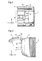
- Fig. 2 shows a wall type indoor unit (right half) of an air conditioner according to an embodiment, as viewed from the front (-X side).
- Fig. 3 shows the indoor unit of Fig. 2 as viewed from the right side (-Y side).
- this air conditioner includes an indoor unit main body 1, and a front panel 4 to be attached to and removed from the indoor unit main body 1.
- the front panel 4 is opened at an opening angle of about 90° with respect to the indoor unit main body 1, being in a fully opened state of a generally horizontal posture.
- an opening 9 of an indoor unit front 3 is closed by the front panel 4.
- a grille (not shown) for intake of the indoor air is formed in a top face 2 of the indoor unit main body 1.
- the front panel 4 has an arm 20 which is protrusively provided on a rear face 40 so as to be inserted into the indoor unit main body 1.
- Fig. 1 corresponds to a sectional view taken along the line A-A of Fig. 2 .
- This arm 20 is composed of a tapered first arm portion 21 extending generally vertical to the rear face 40 of the front panel 4, and a second arm portion 22 which is bent about 90° with respect to the first arm portion 21 and which extends up to a position generally corresponding to an upper edge 41 of the front panel 4.
- a horizontally extending shaft 30 is provided at an end of the second arm portion 22.
- the shaft 30 basically has an outer shape obtained by forming a first chamfer 31, a second chamfer 32 and a third chamfer 33 on a short cylinder defined by a circumferential surface 30s and an end face 30e, each of the chamfers being composed of a flat surface inclined with respect to a center axis.
- Rounds 35 are provided at boundaries between the end face 30e and the chamfers 31, 32, 33, respectively
- rounds 36 are provided at boundaries between the circumferential surface 30s and the chamfers 31, 32, 33, respectively
- rounds 37 are provided at boundaries between each two of the chamfers 31, 32, 33.
- the arm 20 and shaft 30 are provided in one pair in left-and-right symmetry at an upper portion of the rear face of the front panel 4.
- the front panel 4 and the one pair of arm 20 and shaft 30 are made of integrally molded resin.
- the indoor unit main body 1 has a bearing portion 10 for rotatably supporting the shaft 30.
- This bearing portion 10 includes a guide plate 12 having a semicircular peripheral edge 13 curved so as to be recessed frontward (-X direction), and a restraining member 11 (see Fig. 10 ) placed rearward of the guide plate 12 and extending horizontally (Y direction).
- the guide plate 12 has a sloped surface 12f sloped in such a direction as to approach the arm 20 toward the rearward (+X direction).
- the peripheral edge 13 is located rearward of the sloped surface 12f of the guide plate 12.
- the peripheral edge 13 of the guide plate 12 rotatably supports the shaft 30.
- the restraining member 11 restrains a fore end of the second arm portion 22 from moving rearward (+X direction), thereby restraining the shaft 30 from separating off rearward (+X direction) from the position in which the shaft 30 is fitted to the peripheral edge 13 of the guide plate 12.
- the bearing portion 10 is provided in one pair in left-and-right symmetry at an upper portion within the indoor unit main body 1, in correspondence to the one pair of arm 20 and shaft 30 of the front panel 4.
- the first chamfer 31 of the shaft 30 is formed at such a site of the tip circumferential portion of the shaft 30 that the first chamfer 31 faces a lower portion 13b of the peripheral edge 13, while the front panel 4 is in the fully opened state as shown in Fig. 1 .
- the second chamfer 32 of the shaft 30 is formed at such a site of the tip circumferential portion of the shaft 30 that the second chamfer 32 faces a center portion 13a of the peripheral edge 13, while the front panel 4 is in the fully opened state.
- the third chamfer 33 of the shaft 30 is formed at such a site of the tip circumferential portion of the shaft 30 that the third chamfer 33 faces the rearward (+X direction), while the front panel 4 is in the fully opened state.
- the worker When the front panel 4 is attached to the indoor unit main body 1, the worker, holding the front panel 4 horizontally postured in his/her hand, pushes the front panel 4 horizontally from front to rear with the shaft 30 aligned with the sloped surface 12f of the guide plate 12 as shown in Fig. 7 .
- the third chamfer 33 of the shaft 30 (see Fig. 1 ) is guided and inserted along the sloped surface 12f of the guide plate 12 so as to be fitted to the peripheral edge 13 as shown in Fig. 6 .
- the third chamfer 33 formed at the tip circumferential portion of the shaft 30 makes the arm 20 elastically deformed in the same direction as the shaft 30 is separated from the bearing portion 10.
- the front panel 4 can be easily attached to the indoor unit main body 1.
- the front panel 4 is turned around the shaft 30, so that the front panel 4 is closed with respect to the indoor unit main body 1.
- the worker when the front panel 4 is removed from the indoor unit main body 1, the worker, holding the front panel 4 at its lower side portion 42, exerts an external force F so as to pull frontward and lift the front panel 4 as shown in Fig. 1 , by which the front panel 4 is opened from a closed state to a fully opened state with respect to the indoor unit main body 1.
- the front panel 4 is easily turned around the shaft 30.
- the upper edge 41 of the front panel 4 is in contact with a portion 2a of the top face 2 of the indoor unit main body 1 located upper than the opening 9. This is because the length of the arm 20 and the position of the peripheral edge 13 within the indoor unit main body 1 are so set as to yield such a result. Between the arm 20 and an edge 2e that defines the opening 9 is a gap 9a to be left. Accordingly, there is no possibility of collision or resultant damage between the upper edge 41 or the arm 20 of the front panel 4 and the edge 2e defining the opening 9.
- the front panel 4 is supported by an engaging portion formed of an unshown rib provided between the indoor unit main body 1 and the arm 20. Accordingly, even if the worker releases his/her hand off the front panel 4, the posture of the front panel 4 is maintained in the fully opened state.
- a downward force F1 responsive to an external force F applied to the front panel 4 acts on the shaft 30 while the upper edge 41 of the front panel 4 serves as a fulcrum, as shown in Fig. 8 .
- the first chamfer 31 formed at the tip circumferential portion of the shaft 30 is brought into contact with the lower portion 13b of the peripheral edge 13.
- the arm 2C is elastically deformed in such a direction that the shaft 30 is horizontally separated from the bearing portion 10.
- first chamfer 31 slightly crawls into the lower portion 13b of the peripheral edge 13
- the front panel 4 is slightly opened from the fully opened state.
- a frontward force F2 responsive to the external force F applied to the front panel 4 acts on the shaft 30 while the upper edge 41 of the front panel 4 serves as a fulcrum, as shown in Figs. 9 and 10 (equivalent to Fig. 9 , as viewed from diagonal upward).
- the second chamfer 32 formed at the tip circumferential portion of the shaft 30 is brought into contact with the center portion 13a of the peripheral edge 13.
- the arm 20 is further elastically deformed in such a direction that the shaft 30 is horizontally separated from the bearing portion 10, with a result that the shaft 30 is separated off the bearing portion 10.
- Fig. 5 shows a shaft 130 having no parts corresponding to the first and second chamfers.
- This shaft 130 basically has an outer shape obtained by forming a chamfer 133 on a short cylinder defined by a circumferential surface 130s and an end face 130e.
- the chamfer 133 corresponds to the third chamfer 33 in the shaft 30 shown in Fig. 4 .
- An round 135 is provided at a boundary between the end face 130e and the chamfer 133, and an round 136 is provided at a boundary between the a circumferential surface 130s and the chamfer 133.
- the first chamfer 31, the second chamfer 32 and the third chamfer 33 are flat surfaces each inclined with respect to a center axis, respectively, but of course, this is not limitative.
- the first chamfer 31 and the second chamfer 32, or the first chamfer 31 and the second chamfer 32 and the third chamfer 33, may be provided so as to form (part of) a conical surface that tapers as becoming apart from the arm 20 for example, the individual chamfers continuously adjoining one another over a certain angle range about the center axis.
Landscapes
- Engineering & Computer Science (AREA)
- Chemical & Material Sciences (AREA)
- Combustion & Propulsion (AREA)
- Mechanical Engineering (AREA)
- General Engineering & Computer Science (AREA)
- Air Filters, Heat-Exchange Apparatuses, And Housings Of Air-Conditioning Units (AREA)
Abstract
Description
- The present invention relates to an air conditioner and, more particularly, to an air conditioner having a front panel which is to be attached to and removed from the indoor unit main body for conveniences of installation, relocation or the like.
- As an air conditioner of this type, there has been known one in which, as shown in
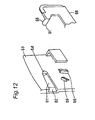
Fig. 12 , anarm 66 to be inserted into an indoor unit main body is protrusively provided at an upper portion of the rear face of a front panel (not shown), with ashaft 65 provided on the arm so as to extend horizontally (see, e.g.,JP H8-135994 A portion 63 for rotatably supporting theshaft 65. In this example, around hole 64, ahorizontal recess 81 adjoining theround hole 64, and a chamferedportion 82 adjoining therecess 81 are provided in thebearing portion 63. Also, at an end of theshaft 65, achamfer 91 is formed at such a site as to just confront therecess 81 with the front panel opened to a certain angle with respect to the main body. - When the front panel is attached to the indoor unit main body, the operator, having the front panel in his/her hand, pushes the front panel horizontally with the
shaft 65 of thearm 66 aligned with thechamfered portion 82. By this operation, theshaft 65 of thearm 66 is guided and inserted along the chamferedportion 82 and therecess 81 so as to be fitted into theround hole 64. After that, the front panel is turned around theshaft 65, thereby closed with respect to the indoor unit main body. On the other hand, when the front panel is removed from the indoor unit main body, the operator, holding a lower side portion of the front panel, lifts the front panel while pulling it frontward, and then turns the front panel around theshaft 65 to open the panel. With the front panel opened to a specified angle, thechamfer 91 of theshaft 65 just confronts therecess 81 while thearm 66 is elastically deformed in such a direction that theshaft 65 is horizontally disengaged from theround hole 64 by aprotrusion 69. In this state, pulling the front panel frontward causes thechamfer 91 to ride on therecess 81 while, with thearm 66 elastically deformed, theshaft 65 is moved frontward along therecess 81, so that the front panel is removed from the indoor unit main body. In addition, aprotrusion 68 is for holding the front panel at an angle halfway. - Generally, workers engaged in installation, relocation or the like of air conditioners treat with a wide variety of air conditioners. For this reason, the worker may, in some cases, try to remove the front panel from the indoor unit main body without grasping correct removal methods for individual machine types.
- In this connection, with the prior-art air conditioner, removal of the front panel involves different kinds of operations such as turning the front panel around the
shaft 65 and moving the front panel horizontally. Therefore, unless a correct removal method is grasped beforehand, the worker will encounter a difficulty in removing the front panel. As a result, there occurs a problem that the worker may exert excessive force on the front panel to damage thearm 66. - Accordingly, it is an object of the present invention to provide an air conditioner which allows the front panel to be easily removed without incurring damage thereon in removal of the front panel from the indoor unit main body.
- In order to achieve the object, an air conditioner according to the present invention comprises an indoor unit main body, and a front panel which is attached to and removed from the indoor unit main body (1), wherein
the front panel includes an arm protrusively provided on a rear face so as to be inserted into the indoor unit main body, the arm having a horizontally extending shaft,
the indoor unit main body includes a bearing portion serving for rotatably supporting the shaft and having at least a peripheral edge curved so as to be recessed frontward, and
a first chamfer is formed at such a site of a tip circumferential portion of the shaft that when the front panel receives an external force in such a direction as to be further opened beyond a fully opened state of a certain opening angle with respect to the indoor unit main body, the first chamfer faces a lower portion of the peripheral edge, so that the first chamfer is brought into contact with the lower portion of the peripheral edge, whereby the arm is elastically deformed in such a direction that the shaft is separated horizontally from the bearing portion. - In the air conditioner of this invention, when the front panel is opened from a closed state to a fully opened state of a certain opening angle with respect to the indoor unit main body, the front panel is turned around the shaft while the shaft keeps supported on the bearing portion. When the front panel is further opened from the fully opened state with respect to the indoor unit main body, the first chamfer formed at the tip circumferential portion of the shaft is brought into contact with the lower portion of the peripheral edge, by which the arm is elastically deformed in such a direction that the shaft is disengaged horizontally from the bearing portion. Therefore, in the fully opened state of the front panel, when the worker applies a little excessive force to the front panel so as to remove the front panel, the shaft is easily disengaged from the bearing portion. Thus, even if the worker does not know a correct removal method beforehand, the worker is enabled to easily remove the front panel from the indoor unit main body without causing any damage. As a result, the cost for servicing replacement can be cut down.
- In the air conditioner of one embodiment, a second chamfer is formed at such a site of the tip circumferential portion of the shaft that when the front panel is opened further from the fully opened state with respect to the indoor unit main body, the second chamfer faces a center portion of the peripheral edge, so that the second chamfer is brought into contact with the center portion of the peripheral edge so as to make the arm elastically deformed, whereby the shaft is separated off the bearing portion.
- In the air conditioner of this one embodiment, when the front panel is further opened from the fully opened state with respect to the indoor unit main body, the second chamfer formed at the tip circumferential portion of the shaft is brought into contact with the center portion of the peripheral edge so as to make the arm elastically deformed, by which the shaft is separated off the bearing portion. That is, in this air conditioner, only one kind of operation of turning the front panel in an opening direction with respect to the indoor unit main body is required to remove the front panel from the indoor unit main body. Therefore, removal of the front panel can be achieved even more easily.
- In the air conditioner of one embodiment, a third chamfer is formed at such a rearward-facing site of the tip circumferential portion of the shaft that when the front panel, while keeping a posture to form the fully opened state, is pushed from frontward to rearward and attached to the indoor unit main body, the third chamfer keeps in contact with a portion of the bearing portion located frontward of the peripheral edge until the shaft reaches the peripheral edge, so that the arm is elastically deformed in one same direction as the shaft is separated off the bearing portion.
- In the air conditioner of this one embodiment, when the front panel, while keeping a posture to form the fully opened state, is pushed from frontward to rearward and attached to the indoor unit main body, the third chamfer formed at the tip circumferential portion of the shaft keeps in contact with a portion of the bearing portion located frontward of the peripheral edge until the shaft reaches the peripheral edge, so that the arm is elastically deformed in one same direction as the shaft is disengaged from the bearing portion. Thus, the front panel can be easily attached to the indoor unit main body.
- In the air conditioner of one embodiment, a length of the arm and a position of the peripheral edge within the indoor unit main body are so set that when the front panel is further opened beyond the fully opened state with respect to the indoor unit main body, an upper edge of the front panel is brought into contact with a portion of the indoor unit main body located upper than an edge of an opening, which is to be closed in a closed state, so that the upper edge serves as a fulcrum by which a force responsive to the external force is exerted on the shaft.
- In the air conditioner of this one embodiment, when the front panel is further opened beyond the fully opened state with respect to the indoor unit main body, the upper edge of the front panel is brought into contact with a portion of the indoor unit main body located upper than the edge of the opening, which is to be closed in a closed state, so that the upper edge serves as a fulcrum on which a force responsive to the external force is exerted on the shaft. Accordingly, when the worker applies a little excessive force to the front panel in a front-panel opening direction to remove the front panel, a force larger than that force is applied to the shaft, so that the shaft is easily separated off the bearing portion. Thus, the front panel can be removed even more easily. Moreover, when the front panel is further opened beyond the fully opened state with respect to the indoor unit main body, there is no possibility that the upper edge of the front panel and the edge of the opening may collide with each other so as to be damaged.
-
-
Fig. 1 is a sectional view showing a portion of an air conditioner according to an embodiment of the present invention in relation to attachment and removal between an indoor unit main body and a front panel; -
Fig. 2 is a view showing the indoor unit (right half) as viewed from the front; -
Fig. 3 is a view showing the indoor unit ofFig. 2 as viewed from the right side; -
Fig. 4 is a view showing a shaft provided at an end of an arm extending from the front panel; -
Fig. 5 is a view showing a shaft in which parts equivalent to the first and second chamfers are not formed, in contrast toFig. 4 ; -
Fig. 6 is a view showing a portion relating to attachment and removal between the indoor unit main body and the front panel, as viewed from the front, with the shaft fitted to the peripheral edge of the bearing portion; -
Fig. 7 is a view showing a portion relating to attachment and removal between the indoor unit main body and the front panel, as viewed from the front, with the shaft removed from the peripheral edge of the bearing portion; -
Fig. 8 is a view showing a state that a downward force responsive to an external force applied to the front panel is acting on the shaft, with an upper edge of the front panel serving as a fulcrum; -
Fig. 9 is a view showing a state that a forward force responsive to an external force applied to the front panel is acting on the shaft, with the upper edge of the front panel serving as a fulcrum; -
Fig. 10 is a view of the state ofFig. 9 , as viewed from diagonal upward; -
Fig. 11 is a view for explaining an action in case that the shaft ofFig. 5 is provided in the arm; and -
Fig. 12 is a view illustrating a portion relating to attachment and removal between the indoor unit main body and the front panel in a conventional air conditioner. - Hereinbelow, the present invention will be described in detail by way of embodiment thereof illustrated in the accompanying drawings.
-
Fig. 2 shows a wall type indoor unit (right half) of an air conditioner according to an embodiment, as viewed from the front (-X side).Fig. 3 shows the indoor unit ofFig. 2 as viewed from the right side (-Y side). As can be seen fromFigs. 2 and 3 , this air conditioner includes an indoor unitmain body 1, and afront panel 4 to be attached to and removed from the indoor unitmain body 1. InFigs. 2 and 3 , thefront panel 4 is opened at an opening angle of about 90° with respect to the indoor unitmain body 1, being in a fully opened state of a generally horizontal posture. When thefront panel 4 is closed and postured generally vertical to the indoor unitmain body 1, an opening 9 of anindoor unit front 3 is closed by thefront panel 4. A grille (not shown) for intake of the indoor air is formed in atop face 2 of the indoor unitmain body 1. - As shown in
Fig. 1 , thefront panel 4 has anarm 20 which is protrusively provided on arear face 40 so as to be inserted into the indoor unitmain body 1. It is noted thatFig. 1 corresponds to a sectional view taken along the line A-A ofFig. 2 . Thisarm 20 is composed of a taperedfirst arm portion 21 extending generally vertical to therear face 40 of thefront panel 4, and asecond arm portion 22 which is bent about 90° with respect to thefirst arm portion 21 and which extends up to a position generally corresponding to anupper edge 41 of thefront panel 4. A horizontally extendingshaft 30 is provided at an end of thesecond arm portion 22. - As shown under magnification in
Fig. 4 , theshaft 30 basically has an outer shape obtained by forming afirst chamfer 31, asecond chamfer 32 and athird chamfer 33 on a short cylinder defined by acircumferential surface 30s and anend face 30e, each of the chamfers being composed of a flat surface inclined with respect to a center axis.Rounds 35 are provided at boundaries between theend face 30e and thechamfers circumferential surface 30s and thechamfers chamfers - The
arm 20 andshaft 30 are provided in one pair in left-and-right symmetry at an upper portion of the rear face of thefront panel 4. Thefront panel 4 and the one pair ofarm 20 andshaft 30 are made of integrally molded resin. - As shown in
Fig. 1 , the indoor unitmain body 1 has a bearingportion 10 for rotatably supporting theshaft 30. This bearingportion 10 includes aguide plate 12 having a semicircularperipheral edge 13 curved so as to be recessed frontward (-X direction), and a restraining member 11 (seeFig. 10 ) placed rearward of theguide plate 12 and extending horizontally (Y direction). As shown inFig. 6 (corresponding to a sectional view taken along the line B-B inFig. 3 ), theguide plate 12 has a slopedsurface 12f sloped in such a direction as to approach thearm 20 toward the rearward (+X direction). Theperipheral edge 13 is located rearward of the slopedsurface 12f of theguide plate 12. As shown inFig. 1 , with thefront panel 4 attached to the indoor unitmain body 1, theperipheral edge 13 of theguide plate 12 rotatably supports theshaft 30. The restrainingmember 11 restrains a fore end of thesecond arm portion 22 from moving rearward (+X direction), thereby restraining theshaft 30 from separating off rearward (+X direction) from the position in which theshaft 30 is fitted to theperipheral edge 13 of theguide plate 12. - The bearing
portion 10 is provided in one pair in left-and-right symmetry at an upper portion within the indoor unitmain body 1, in correspondence to the one pair ofarm 20 andshaft 30 of thefront panel 4. - The
first chamfer 31 of theshaft 30 is formed at such a site of the tip circumferential portion of theshaft 30 that thefirst chamfer 31 faces alower portion 13b of theperipheral edge 13, while thefront panel 4 is in the fully opened state as shown inFig. 1 . Also, thesecond chamfer 32 of theshaft 30 is formed at such a site of the tip circumferential portion of theshaft 30 that thesecond chamfer 32 faces acenter portion 13a of theperipheral edge 13, while thefront panel 4 is in the fully opened state. Thethird chamfer 33 of theshaft 30 is formed at such a site of the tip circumferential portion of theshaft 30 that thethird chamfer 33 faces the rearward (+X direction), while thefront panel 4 is in the fully opened state. - When the
front panel 4 is attached to the indoor unitmain body 1, the worker, holding thefront panel 4 horizontally postured in his/her hand, pushes thefront panel 4 horizontally from front to rear with theshaft 30 aligned with thesloped surface 12f of theguide plate 12 as shown inFig. 7 . By this operation, thethird chamfer 33 of the shaft 30 (seeFig. 1 ) is guided and inserted along the slopedsurface 12f of theguide plate 12 so as to be fitted to theperipheral edge 13 as shown inFig. 6 . - For a duration until the
shaft 30 reaches theperipheral edge 13, thethird chamfer 33 formed at the tip circumferential portion of theshaft 30 makes thearm 20 elastically deformed in the same direction as theshaft 30 is separated from the bearingportion 10. Thus, thefront panel 4 can be easily attached to the indoor unitmain body 1. - After that, with the
shaft 30 supported on the bearingportion 10, thefront panel 4 is turned around theshaft 30, so that thefront panel 4 is closed with respect to the indoor unitmain body 1. - On the other hand, when the
front panel 4 is removed from the indoor unitmain body 1, the worker, holding thefront panel 4 at itslower side portion 42, exerts an external force F so as to pull frontward and lift thefront panel 4 as shown inFig. 1 , by which thefront panel 4 is opened from a closed state to a fully opened state with respect to the indoor unitmain body 1. In this operation, with theshaft 30 supported on the bearingportion 10, thefront panel 4 is easily turned around theshaft 30. - In the fully opened state, the
upper edge 41 of thefront panel 4 is in contact with aportion 2a of thetop face 2 of the indoor unitmain body 1 located upper than theopening 9. This is because the length of thearm 20 and the position of theperipheral edge 13 within the indoor unitmain body 1 are so set as to yield such a result. Between thearm 20 and anedge 2e that defines theopening 9 is agap 9a to be left. Accordingly, there is no possibility of collision or resultant damage between theupper edge 41 or thearm 20 of thefront panel 4 and theedge 2e defining theopening 9. - In this fully opened state, the
front panel 4 is supported by an engaging portion formed of an unshown rib provided between the indoor unitmain body 1 and thearm 20. Accordingly, even if the worker releases his/her hand off thefront panel 4, the posture of thefront panel 4 is maintained in the fully opened state. - When the worker attempts to open the
front panel 4 further beyond the fully opened state with respect to the indoor unitmain body 1, a downward force F1 responsive to an external force F applied to thefront panel 4 acts on theshaft 30 while theupper edge 41 of thefront panel 4 serves as a fulcrum, as shown inFig. 8 . Thus, thefirst chamfer 31 formed at the tip circumferential portion of theshaft 30 is brought into contact with thelower portion 13b of theperipheral edge 13. As a result of this, the arm 2C is elastically deformed in such a direction that theshaft 30 is horizontally separated from the bearingportion 10. To an extent thatfirst chamfer 31 slightly crawls into thelower portion 13b of theperipheral edge 13, thefront panel 4 is slightly opened from the fully opened state. - From this state, when the worker attempts to further open the
front panel 4 with respect to the indoor unitmain body 1, a frontward force F2 responsive to the external force F applied to thefront panel 4 acts on theshaft 30 while theupper edge 41 of thefront panel 4 serves as a fulcrum, as shown inFigs. 9 and10 (equivalent toFig. 9 , as viewed from diagonal upward). Thus, thesecond chamfer 32 formed at the tip circumferential portion of theshaft 30 is brought into contact with thecenter portion 13a of theperipheral edge 13. As a result of this, thearm 20 is further elastically deformed in such a direction that theshaft 30 is horizontally separated from the bearingportion 10, with a result that theshaft 30 is separated off the bearingportion 10. - As shown above, in the fully opened state of the
front panel 4, when the worker applies a little excessive force to thefront panel 4 so as to remove thefront panel 4, theshaft 30 is easily separated off the bearingportion 10. Also, since a force larger than the external force F is applied to theshaft 30 with theupper edge 41 of thefront panel 4 serving as a fulcrum, theshaft 30 is even more easily removed from the bearingportion 10. Accordingly, it is easily achievable to remove thefront panel 4 from the indoor unitmain body 1. Yet, only one kind of operation to turn thefront panel 4 in an opening direction with respect to the indoor unitmain body 1 is enough to remove thefront panel 4 from the indoor unitmain body 1. Therefore, removal of thefront panel 4 can be achieved even more easily. Still more, when thefront panel 4 is further opened from the fully opened state with respect to the indoor unitmain body 1, there is no possibility of collision or resultant damage between theupper edge 41 or thearm 20 of thefront panel 4 and theedge 2e defining theopening 9. - Thus, according to this air conditioner, even if the worker does not know a correct removal method beforehand, the worker is enabled to easily remove the
front panel 4 from the indoor unitmain body 1 without incurring their damage. As a result, the cost for servicing replacement can be cut down. - In addition, in contrast to the
shaft 30 shown inFig. 4, Fig. 5 shows ashaft 130 having no parts corresponding to the first and second chamfers. Thisshaft 130 basically has an outer shape obtained by forming achamfer 133 on a short cylinder defined by acircumferential surface 130s and anend face 130e. Thechamfer 133 corresponds to thethird chamfer 33 in theshaft 30 shown inFig. 4 . Anround 135 is provided at a boundary between theend face 130e and thechamfer 133, and anround 136 is provided at a boundary between the acircumferential surface 130s and thechamfer 133. Without parts corresponding to the above-described first and second chamfers as shown in thisshaft 130, if a frontward force F2 responsive to the external force F applied to thefront panel 4 acts on theshaft 130 as shown inFig. 11 as an example, theshaft 130 is never separated off theperipheral edge 13. Thus, preferable functional effects of the present invention cannot be obtained. - In the above-described embodiment, the
first chamfer 31, thesecond chamfer 32 and thethird chamfer 33 are flat surfaces each inclined with respect to a center axis, respectively, but of course, this is not limitative. Thefirst chamfer 31 and thesecond chamfer 32, or thefirst chamfer 31 and thesecond chamfer 32 and thethird chamfer 33, may be provided so as to form (part of) a conical surface that tapers as becoming apart from thearm 20 for example, the individual chamfers continuously adjoining one another over a certain angle range about the center axis.
Claims (4)
- An air conditioner comprising an indoor unit main body (1), and a front panel (4) which is attached to and removed from the indoor unit main body (1), wherein
the front panel (4) includes an arm (20) protrusively provided on a rear face (40) so as to be inserted into the indoor unit main body (1), the arm (20) having a horizontally extending shaft (30),
the indoor unit main body (1) includes a bearing portion (10) serving for rotatably supporting the shaft (30) and having at least a peripheral edge (13) curved so as to be recessed frontward, and
a first chamfer (31) is formed at such a site of a tip circumferential portion of the shaft (30) that when the front panel (4) receives an external force (F) in such a direction as to be further opened beyond a fully opened state of a certain opening angle with respect to the indoor unit main body (1), the first chamfer (31) faces a lower portion (13b) of the peripheral edge (13), so that the first chamfer (31) is brought into contact with the lower portion (13b) of the peripheral edge (13), whereby the arm (20) is elastically deformed in such a direction that the shaft (30) is separated horizontally from the bearing portion (10). - The air conditioner as claimed in Claim 1, wherein
a second chamfer (32) is formed at such a site of the tip circumferential portion of the shaft (30) that when the front panel (4) is opened further from the fully opened state with respect to the indoor unit main body (1), the second chamfer (32) faces a center portion (13a) of the peripheral edge (13), so that the second chamfer (32) is brought into contact with the center portion (13a) of the peripheral edge (13) so as to make the arm (20) elastically deformed, whereby the shaft (30) is separated off the bearing portion (10). - The air conditioner as claimed in Claim 1, wherein
a third chamfer (33) is formed at such a rearward-facing site of the tip circumferential portion of the shaft (30) that when the front panel (4), while keeping a posture to form the fully opened state, is pushed from frontward to rearward and attached to the indoor unit main body (1), the third chamfer (33) keeps in contact with a portion (12f) of the bearing portion (10) located frontward of the peripheral edge (13) until the shaft (30) reaches the peripheral edge (13), so that the arm (20) is elastically deformed in one same direction as the shaft (30) is separated off the bearing portion (10). - The air conditioner as claimed in Claim 1, wherein
a length of the arm (22) and a position of the peripheral edge (13) within the indoor unit main body (1) are so set that when the front panel (4) is further opened beyond the fully opened state with respect to the indoor unit main body (1), an upper edge (4) of the front panel (4) is brought into contact with a portion (2a) of the indoor unit main body (1) located upper than an edge (2e) of an opening (9), which is to be closed in a closed state, so that the upper edge (41) serves as a fulcrum by which a force (F1, F2) responsive to the external force (F) is exerted on the shaft (30).
Applications Claiming Priority (2)
| Application Number | Priority Date | Filing Date | Title |
|---|---|---|---|
| JP2006229308A JP4055811B1 (en) | 2006-08-25 | 2006-08-25 | Air conditioner |
| PCT/JP2007/066434 WO2008023785A1 (en) | 2006-08-25 | 2007-08-24 | Air conditioner |
Publications (2)
| Publication Number | Publication Date |
|---|---|
| EP2071252A1 true EP2071252A1 (en) | 2009-06-17 |
| EP2071252A4 EP2071252A4 (en) | 2014-03-12 |
Family
ID=39106867
Family Applications (1)
| Application Number | Title | Priority Date | Filing Date |
|---|---|---|---|
| EP07792963.6A Withdrawn EP2071252A4 (en) | 2006-08-25 | 2007-08-24 | AIR CONDITIONER |
Country Status (6)
| Country | Link |
|---|---|
| EP (1) | EP2071252A4 (en) |
| JP (1) | JP4055811B1 (en) |
| KR (1) | KR101060366B1 (en) |
| CN (1) | CN101484760B (en) |
| AU (1) | AU2007288704B2 (en) |
| WO (1) | WO2008023785A1 (en) |
Cited By (1)
| Publication number | Priority date | Publication date | Assignee | Title |
|---|---|---|---|---|
| CN114659259A (en) * | 2020-12-22 | 2022-06-24 | 宁波奥克斯电气股份有限公司 | Air conditioner shell and air conditioner |
Families Citing this family (6)
| Publication number | Priority date | Publication date | Assignee | Title |
|---|---|---|---|---|
| CN105352160B (en) * | 2014-08-21 | 2018-10-12 | 青岛海尔空调器有限总公司 | Wall-hanging air conditioner indoor unit and wall-hanging air conditioner |
| CN206847028U (en) * | 2016-01-18 | 2018-01-05 | 三菱电机株式会社 | Indoor unit of air conditioner |
| JP7088903B2 (en) * | 2017-02-27 | 2022-06-21 | シャープ株式会社 | Closure opening / closing mechanism, air conditioner |
| CN108917152B (en) * | 2018-07-20 | 2020-10-27 | Tcl空调器(中山)有限公司 | Panel and middle frame mounting structure, mounting method and air conditioner |
| CN110748952B (en) * | 2018-07-23 | 2022-06-21 | 大金工业株式会社 | Indoor unit of air conditioner |
| WO2021240703A1 (en) * | 2020-05-28 | 2021-12-02 | 三菱電機株式会社 | Indoor unit for air conditioner |
Family Cites Families (4)
| Publication number | Priority date | Publication date | Assignee | Title |
|---|---|---|---|---|
| JP3121505B2 (en) | 1994-11-02 | 2001-01-09 | 三菱電機株式会社 | Air conditioner |
| JP2904078B2 (en) * | 1995-11-16 | 1999-06-14 | ダイキン工業株式会社 | Panel mounting structure |
| CN2272934Y (en) * | 1996-12-11 | 1998-01-21 | 青岛海尔空调器有限总公司 | Dismountable hinge hook for hanging face plate |
| JPH1151417A (en) * | 1997-07-30 | 1999-02-26 | Daikin Ind Ltd | Panel mounting structure |
-
2006
- 2006-08-25 JP JP2006229308A patent/JP4055811B1/en not_active Expired - Fee Related
-
2007
- 2007-08-24 CN CN2007800235912A patent/CN101484760B/en not_active Expired - Fee Related
- 2007-08-24 EP EP07792963.6A patent/EP2071252A4/en not_active Withdrawn
- 2007-08-24 KR KR1020087030657A patent/KR101060366B1/en not_active Expired - Fee Related
- 2007-08-24 WO PCT/JP2007/066434 patent/WO2008023785A1/en not_active Ceased
- 2007-08-24 AU AU2007288704A patent/AU2007288704B2/en not_active Ceased
Cited By (1)
| Publication number | Priority date | Publication date | Assignee | Title |
|---|---|---|---|---|
| CN114659259A (en) * | 2020-12-22 | 2022-06-24 | 宁波奥克斯电气股份有限公司 | Air conditioner shell and air conditioner |
Also Published As
| Publication number | Publication date |
|---|---|
| JP4055811B1 (en) | 2008-03-05 |
| KR101060366B1 (en) | 2011-08-29 |
| CN101484760B (en) | 2012-04-25 |
| EP2071252A4 (en) | 2014-03-12 |
| CN101484760A (en) | 2009-07-15 |
| AU2007288704B2 (en) | 2010-05-20 |
| WO2008023785A1 (en) | 2008-02-28 |
| JP2008051434A (en) | 2008-03-06 |
| KR20090016585A (en) | 2009-02-16 |
| AU2007288704A1 (en) | 2008-02-28 |
Similar Documents
| Publication | Publication Date | Title |
|---|---|---|
| AU2007288704B2 (en) | Air conditioner | |
| EP2684653A1 (en) | Robot system and method for manufacturing fitting | |
| US7461792B2 (en) | Fixture of memory card base | |
| JPH11283687A (en) | Connector | |
| JPH1190061A (en) | Knife holder | |
| JP7348391B2 (en) | Fastener | |
| EP1562017A2 (en) | Motor-fan shroud with reservoir tank | |
| US6765148B2 (en) | C-shaped grommet | |
| JP2011169572A (en) | Handle for outdoor unit, outdoor unit including the handle and method of carrying outdoor unit | |
| US11400571B2 (en) | Tongue break-off tool and tongue break-off method | |
| JP4636039B2 (en) | Air conditioner | |
| JP4636038B2 (en) | Air conditioner | |
| CN210196126U (en) | Fan blade mounting structure with elastic buckle, fan and air conditioner | |
| JP6544729B2 (en) | Vehicle air conditioner | |
| JPH10148052A (en) | Lid attach / detach configuration | |
| JP2010253998A (en) | Inner cable connection structure and sliding door drive device using the same | |
| JPH11247516A (en) | Attaching/detaching tool and fitting structure provided therewith for plate body | |
| JP2021055678A (en) | cover | |
| JPH08230515A (en) | Cluster mounting structure | |
| JP2009017747A (en) | Double blade clamp and wire harness | |
| CN113286541B (en) | Container with attachable/detachable handle | |
| JP6949247B2 (en) | Outdoor unit of air conditioner | |
| KR20260011953A (en) | Housing spacer fastening structure | |
| JPH0111421Y2 (en) | ||
| JP2025005612A (en) | Vehicle cover structure |
Legal Events
| Date | Code | Title | Description |
|---|---|---|---|
| PUAI | Public reference made under article 153(3) epc to a published international application that has entered the european phase |
Free format text: ORIGINAL CODE: 0009012 |
|
| 17P | Request for examination filed |
Effective date: 20090325 |
|
| AK | Designated contracting states |
Kind code of ref document: A1 Designated state(s): AT BE BG CH CY CZ DE DK EE ES FI FR GB GR HU IE IS IT LI LT LU LV MC MT NL PL PT RO SE SI SK TR |
|
| AX | Request for extension of the european patent |
Extension state: AL BA HR MK RS |
|
| DAX | Request for extension of the european patent (deleted) | ||
| A4 | Supplementary search report drawn up and despatched |
Effective date: 20140207 |
|
| RIC1 | Information provided on ipc code assigned before grant |
Ipc: F24F 13/20 20060101AFI20140203BHEP Ipc: F24F 1/00 20110101ALI20140203BHEP |
|
| RIC1 | Information provided on ipc code assigned before grant |
Ipc: F24F 1/00 20110101ALI20140829BHEP Ipc: F24F 13/20 20060101AFI20140829BHEP |
|
| GRAP | Despatch of communication of intention to grant a patent |
Free format text: ORIGINAL CODE: EPIDOSNIGR1 |
|
| INTG | Intention to grant announced |
Effective date: 20141016 |
|
| STAA | Information on the status of an ep patent application or granted ep patent |
Free format text: STATUS: THE APPLICATION IS DEEMED TO BE WITHDRAWN |
|
| 18D | Application deemed to be withdrawn |
Effective date: 20150227 |