EP2071250A1 - Electric component unit - Google Patents
Electric component unit Download PDFInfo
- Publication number
- EP2071250A1 EP2071250A1 EP07807661A EP07807661A EP2071250A1 EP 2071250 A1 EP2071250 A1 EP 2071250A1 EP 07807661 A EP07807661 A EP 07807661A EP 07807661 A EP07807661 A EP 07807661A EP 2071250 A1 EP2071250 A1 EP 2071250A1
- Authority
- EP
- European Patent Office
- Prior art keywords
- component unit
- electrical component
- electrical components
- plate
- reactor
- Prior art date
- Legal status (The legal status is an assumption and is not a legal conclusion. Google has not performed a legal analysis and makes no representation as to the accuracy of the status listed.)
- Withdrawn
Links
- 238000005192 partition Methods 0.000 description 13
- 238000007664 blowing Methods 0.000 description 11
- 239000000463 material Substances 0.000 description 8
- 239000003507 refrigerant Substances 0.000 description 8
- 238000009423 ventilation Methods 0.000 description 8
- 238000003780 insertion Methods 0.000 description 7
- 230000037431 insertion Effects 0.000 description 7
- 239000011347 resin Substances 0.000 description 4
- 229920005989 resin Polymers 0.000 description 4
- 239000003990 capacitor Substances 0.000 description 2
- 238000005452 bending Methods 0.000 description 1
- 230000000694 effects Effects 0.000 description 1
- 239000003063 flame retardant Substances 0.000 description 1
- NBVXSUQYWXRMNV-UHFFFAOYSA-N fluoromethane Chemical compound FC NBVXSUQYWXRMNV-UHFFFAOYSA-N 0.000 description 1
- 238000012423 maintenance Methods 0.000 description 1
- 239000002184 metal Substances 0.000 description 1
Images




Classifications
-
- F—MECHANICAL ENGINEERING; LIGHTING; HEATING; WEAPONS; BLASTING
- F24—HEATING; RANGES; VENTILATING
- F24F—AIR-CONDITIONING; AIR-HUMIDIFICATION; VENTILATION; USE OF AIR CURRENTS FOR SCREENING
- F24F1/00—Room units for air-conditioning, e.g. separate or self-contained units or units receiving primary air from a central station
- F24F1/06—Separate outdoor units, e.g. outdoor unit to be linked to a separate room comprising a compressor and a heat exchanger
- F24F1/20—Electric components for separate outdoor units
-
- F—MECHANICAL ENGINEERING; LIGHTING; HEATING; WEAPONS; BLASTING
- F24—HEATING; RANGES; VENTILATING
- F24F—AIR-CONDITIONING; AIR-HUMIDIFICATION; VENTILATION; USE OF AIR CURRENTS FOR SCREENING
- F24F1/00—Room units for air-conditioning, e.g. separate or self-contained units or units receiving primary air from a central station
- F24F1/06—Separate outdoor units, e.g. outdoor unit to be linked to a separate room comprising a compressor and a heat exchanger
- F24F1/20—Electric components for separate outdoor units
- F24F1/22—Arrangement or mounting thereof
-
- F—MECHANICAL ENGINEERING; LIGHTING; HEATING; WEAPONS; BLASTING
- F24—HEATING; RANGES; VENTILATING
- F24F—AIR-CONDITIONING; AIR-HUMIDIFICATION; VENTILATION; USE OF AIR CURRENTS FOR SCREENING
- F24F1/00—Room units for air-conditioning, e.g. separate or self-contained units or units receiving primary air from a central station
- F24F1/06—Separate outdoor units, e.g. outdoor unit to be linked to a separate room comprising a compressor and a heat exchanger
- F24F1/20—Electric components for separate outdoor units
- F24F1/24—Cooling of electric components
Definitions
- the present invention relates to an electrical component unit. More specifically, the present invention relates to an electrical component unit that supports electrical components including a specific heat generating component in an outdoor unit of an air conditioner.
- an outdoor unit of an air conditioner includes a heat exchanger, an outdoor fan, a compressor, a reactor, and the like in an outdoor unit casing generally made of a fire retardant material.
- an electrical component unit in which various electrical components such as a power transistor and a capacitor are embedded is disposed in the outdoor unit casing.
- a control circuit in the electrical component unit supplies drive power to the outdoor fan, the compressor, and the like, and also controls driving of these components.
- the reactor be disposed in the vicinity of the electrical component unit in terms of a wire, however, because it is necessary to make the electrical component unit less subject to heat generated by the reactor, it is problematic to dispose the reactor at a position too close to the electrical component unit (see Patent Document 1). Accordingly, the reactor is attached to a position away from the electrical component unit.
- Objects of the present invention are to prevent an outdoor unit casing of an air conditioner from becoming large and to reduce the cost.
- An electrical component unit is an electrical component unit that houses a plurality of electrical components including a specific heat generating component in an outdoor unit of an air conditioner, the electrical component unit including a support member and a reactor.
- the support member includes an arrangement portion in which some of the plurality of electrical components can be arranged, and a projecting portion outwardly projecting from the arrangement portion.
- the reactor is one of the plurality of electrical components. It is disposed away from other electrical components and attached to the projecting portion.
- this electrical component unit some of the plurality of electrical components are arranged in the arrangement portion of the support member, and the reactor is attached to the projecting portion so as to be away from other electrical components.
- the reactor is attached to the projecting portion of the support member to which, as the electrical component unit, the plurality of electrical components are attached, it is possible to reduce materials necessary for a wire and reduce the size and cost of the outdoor unit.
- An electrical component unit is the electrical component unit according to the first aspect of the present invention, wherein the support member further includes a lower plate-like portion disposed so as to extend downwardly from a second end portion of the projecting portion, the second end portion being located oppositely to a first end portion on the arrangement portion side of the projecting portion, and the lower plate-like portion being configured such that a terminal plate including terminals of the plurality of electrical components can be arranged thereon.
- the terminal plate is attached to the lower plate-like portion that extends from the second end portion of the projecting portion, the second end portion being located oppositely to the first end portion on the arrangement portion side of the projecting portion.
- the terminal plate can be integrally supported by the electrical component unit.
- An electrical component unit is the electrical component unit according to the first or second aspect of the present invention, wherein the arrangement portion includes a plate-like portion disposed above the electrical components other than the reactor, and a lateral side support portion disposed laterally to the electrical components other than the reactor so as to hang down from the plate-like portion.
- a bottom end portion of the lateral side support portion and a bottom end portion of the lower plate-like portion are located at substantially the same height.
- the electrical component unit when mounting the electrical component unit to the outdoor unit of the air conditioner, the electrical component unit may be temporarily placed on a table or the like to perform such work.
- the electrical component unit because the bottom end portion of the lateral side support portion and the bottom end portion of the lower plate-like portion are located at substantially the same height, the electrical component unit can be placed keeping its position (a state in which bottom end portion of the lateral side support portion and the bottom end portion of the lower plate-like portion are in contact with the table), which improves workability.
- An electrical component unit according to a fourth aspect of the present invention is the electrical component unit according to any one of the first through third aspects of the present invention, wherein the support member is made of a fireproof member.
- the support member is made of a fireproof member. Accordingly, even if the plurality of electrical components are burned, it is possible to reduce a risk of burning other components.
- An electrical component unit according to a fifth aspect of the present invention is the electrical component unit according to any one of the first through fourth aspects of the present invention, the electrical component unit having a depression-shaped portion formed on the top surface thereof so as to extend in a projection direction of the projecting portion.
- a depression-shaped portion is formed on the top surface of the projecting portion so as to extend along the projecting direction. Accordingly, the strength in the projecting direction is further increased. Accordingly, it is possible to further stabilize the support of the reactor.
- the reactor is attached to the projecting portion of the support member to which, as the electrical component unit, the plurality of electrical components are attached, it is possible to reduce materials necessary for a wire and reduce the size and cost of the outdoor unit.
- the terminal plate can be integrally supported by the electrical component unit.
- the electrical component unit because the bottom end portions of some of the electrical components and the bottom end portion of the lower plate-like portion are located at substantially the same height, the electrical component unit can be placed keeping its position (in a standing position with the bottom end portions of some of the electrical components and the bottom end portion of the lower plate-like portion used as the legs), which improves workability.
- FIG 1 shows an air conditioner 1 including an electrical component unit 5 (see Figure 3 and the like) according to an embodiment of the present invention.
- the air conditioner 1 includes an indoor unit 2 mounted in a building, an outdoor unit 3 disposed outside, and a refrigerant pipe 4 that connects the outdoor unit 3 to the indoor unit 2. Because the present invention relates to the electrical component unit 5 disposed inside the outdoor unit 3, the outdoor unit 3 is mainly described.
- FIGS 2 and 3 show the outdoor unit 3.
- the outdoor unit 3 includes a casing 31, a heat exchanger 32, a compressor 33, an air blowing unit 34, and the electrical component unit 5.
- the inside of the outdoor unit 3 is divided by a partition plate 35 into a machine space 37 where the electrical component unit 5 and the compressor 33 are disposed and a ventilation space 36 where the heat exchanger 32, a fan 343, and the like are disposed.
- the partition plate 35 is a flat plate shaped member and includes a cutout 351 in a substantially rectangular shape.
- rails 352 each having a predetermined length is provided to the upper portion of the cutout 351, and a plate-like member 354 having a rectangular opening 353 is provided to the lower portion of the cutout 351. Note that the electrical component unit 5 is described later.
- the casing 31 is a member having a substantially rectangular parallelepiped shape, and is made of sheet metal and a resin.
- the casing 31 includes an air blowing port 311a and an air intake (not shown).
- the casing 31 sucks in air from the air intake and blows out the air from the air blowing port 311a.
- the air blowing port 311a and the air intake are disposed on the ventilation space 36 side.
- the casing 31 includes a case main body 311, a case lateral wall portion 312, and a resin cover 313.
- the case main body 311 is a member that covers the compressor 33 and the heat exchanger 32.
- the case lateral wall portion 312 is disposed to the lateral end portion on the machine space 37 side of the case main body, and is a plate shaped member having an opening 312a.
- the resin cover 313 is attached to the outside of the lateral wall portion 312, and is a plate-like member that covers a part of the refrigerant pipe 4.
- the heat exchanger 32 is an L-shaped device.
- the heat exchanger 32 includes a fin portion 321 in which a plurality of fins are arranged in an L-shape, and a pipe 322 bent several times and disposed in a supported manner by the fin portion 321.
- a refrigerant, such as a fluorocarbon flows through the inside of the pipe 322.
- the compressor 33 is disposed in the vicinity of the partition plate 35 of the machine space 37, and is a machine to compress the refrigerant. It is a machine that, for example, to compress low pressure refrigerant gas into high pressure refrigerant gas.
- the compressor 33 is disposed below the electrical component unit 5.
- the compressor 33 includes a cylindrical case 331 and devices such as a mechanism and an electric motor (not shown) for compressing the refrigerant. The devices such as the mechanism and the electric motor for compressing the refrigerant are disposed inside the cylindrical case 331.
- the air blowing unit 34 is a member disposed in the ventilation space 36, and is configured to blow out air from the inside of the ventilation space 36 to the outside.
- the air blowing unit 34 includes a fan motor 341, a fan table 342, and the fan 343.
- the fan motor 341 generates power to rotate the fan 343, and includes a cylindrical motor portion 341a, and a rotation shaft 341b rotated by the cylindrical motor portion 341a and projects from the cylindrical motor portion 341 a to the air blowing port 311 a side.
- the fan table 342 is a member attached to the fin portion 321, and includes a fixed portion 342a, a support member projecting portion 342b, and a fan motor support portion 342c.
- the fixed portion 342a is a portion disposed on the upper side of the heat exchanger 32.
- the support member projecting portion 342b is a portion that projects from the fixed portion 342a to the air blowing port 311 a side.
- the leading end on the air blowing port 311a side of the support member projecting portion 342b is bent in the downward direction of Figure 3 .
- the support member projecting portion 342b has a large and substantially rectangular shaped opening in the center thereof.
- the fan motor support portion 342c is a plate-like portion that extends in a vertically downward direction from the support member projecting portion 342b to the bottom of the casing 31, and is a portion to which the fan motor 341 is attached.
- the majority of the weight of the fan motor 341, the fan table 342, and the fan 343 is supported by the bottom of the casing 31 by the fan motor support portion 342c.
- the fan motor support portion 342c is configured such that its both ends in a direction perpendicular to the longitudinal direction are bent, thus increasing the strength compared to the case where the fan motor support portion is formed by a flat plate.
- the fan 343 is a member attached to the rotation shaft 341 b of the fan motor 341, and is configured to blow out air in the outdoor unit 3 through the air blowing port 311 a.
- the fan 343 includes a tubular portion 343a attached to the rotation shaft 341b in a manner incapable of performing relative rotation and three blade members 343b attached to the lateral surface of the tubular portion 343a. Further, the fan 343 is disposed so as to face the air blowing port 311a in order to discharge air in the ventilation space 36 to the outside.
- the electrical component unit 5 is disposed above the compressor 33, and is supported by the partition plate 35 and the casing 31.
- the electrical component unit 5 includes a support member 51, a plurality of electrical components 52 including a reactor 521, and a terminal plate 53.
- the support member 51 is a member that supports the electrical components 52 and the terminal plate 53, and is disposed adjacent to the top surface of the casing 31.
- the support member 51 includes an arrangement portion 511, a projecting portion 512, and a lower plate-like portion 513.
- the arrangement portion 511 is a portion that supports the electrical components 52 other than the reactor 521, and includes: an upper plate-like portion 511a having a plate-like disposed above the electrical components 52 other than the reactor 521; a lateral side support portion 511b disposed laterally to the electrical components 52 other than the reactor 521; and a lower support plate portion 511d disposed below the electrical components 52 other than the reactor 521.
- the electrical components 52 are disposed between the upper plate-like portion 511a and the lower support plate portion 511d of the arrangement portion 511.
- the projecting portion 512 is a plate-like portion that projects from the upper plate-like portion 511a of the arrangement portion 511 in a direction opposite to the direction where the ventilation space 36 is arranged.
- the projecting portion 512 is a hollow member formed by bending a first flat plate 512a projecting from the upper plate-like portion 511a such that the first flat plate 512a is in a substantially U shape and by connecting a second flat plate 512b to both ends of the first flat plate 512a so as to connect the both ends.
- the lower plate-like portion 513 is a portion extending downwardly from an end portion of the projecting portion 512, the end portion being located oppositely to another end on the arrangement portion 511 side of the projecting portion 512.
- the lower plate-like portion 513 includes a terminal plate attachment portion 513a, a support portion 513b, and lateral wall portions 513c.
- the terminal plate attachment portion 513a is a portion formed in a flat plate shape, to which the terminal plate 53 is attached.
- the support portion 513b is a portion disposed below the terminal plate attachment portion 513a, and is a portion supported by the casing 31.
- the support portion 513b is provided with a wire support portion 513d for supporting wires of the terminal plate 53.
- the lateral wall portions 513c are plate-like portions outwardly extending from both lateral sides of the terminal attachment portion 513a. Note that a bottom end portion 511c of the lateral side support portions 511b and a lower end portion 513e of the lower plate-like portion 513 are located at substantially the same height.
- the casing 31 has the opening 312a at a portion corresponding to the position where the terminal plate attachment portion 513a is disposed.
- the opening 312a is disposed such that a wire is passed through the opening 312a for connecting to the external power supply (see Figure 2 ).
- a shielding plate 6 made of a nonflammable resin material so as to cover the opening 312a is disposed. Accordingly, even if the inside of the machine space 37 catches fire, the impact of the fire on the outside of the machine space 37 is reduced.
- the shielding plate 6 is configured to support the wire connected to the terminal plate 53 and also to block between the machine space 37 side and the outside.
- the plurality of electrical components 52 are the members supported by the arrangement portion 511, and includes the reactor 521, a power transistor, a plurality of capacitors, and the like.
- the reactor 521 is a substantially cubic shaped member which is attached to the projecting portion 512 of the support member 51. In addition, the reactor 521 is disposed with a slight distance from other electrical components 52.
- Heat radiating fins 522 are mounted to the power transistor. As shown in Figure 6 , the heat radiating fins 522 are provided as a device to transfer heat from the power transistor, and are supported by the cutout 351 of the partition plate 35. An insertion opening 523 is provided in the vicinity of the heat radiating fin 522.
- the insertion opening 523 is formed between the support member 51 of the electrical component unit 5 and an insertion plate 523a provided with a predetermined space from the support member 51.
- the electrical component unit 5 is supported by the partition plate 35 as the rails 352 of the partition plate 35 are slid into the insertion opening 523.
- the insertion plate 523a is formed to extend a predetermined distance from the upper end portion of the partition plate 35 in Figure 6 , and has the same length as the rails 352 of the partition plate 35. Accordingly, the insertion plate 523a will not cover the entire periphery of the cutout 351 of the partition plate 35.
- the heat radiating fin 522 has an engaging portion (not shown) at the bottom thereof that engages with the rectangular opening 354 of the plate-like portion provided to the cutout 351 of the partition plate 35.
- the terminal plate 53 is a member attached to the terminal plate attachment portion 513a of the support member 51, and two power supply lines and one signal line are connected to the terminal plate 53.
- the two power supply lines are connected to the indoor unit 2 of the air conditioner 1, and the electric power is supplied from the power supply via the indoor unit 2 of the air conditioner 1.
- One signal line is a line for exchanging signals with the indoor unit 2 of the air conditioner 1.
- the support member 51 of the electrical component unit 5 includes the arrangement portion 511 that supports the electrical components 52 and the projecting portion 512 that projects from the arrangement portion 511 toward the end portion of the casing 31, and the reactor 521 is attached to the projecting portion 512. Accordingly, the electrical components 52 other than the reactor 521 can be disposed at a position near the reactor 521. Accordingly, the electrical components 52 other than the reactor 521 and the reactor 521 can be handled as one unit, which increases the design flexibility. Further, because the reactor 521 is disposed at a position away and above the electrical components 52, the electrical components 52 are less subject to heat generated by the reactor 521. Additionally, because the terminal plate 53 can be disposed to the electrical component unit 5, it is possible to reduce materials for a wire and the like and lower the cost.
- the bottom end portion 511c of the lateral side support portion 511b and the lower end portion 513e of the lower plate-like portion 513 are located at substantially the same height, so that the electrical component unit 5 can be kept in the position shown in Figure 5 when placing the electrical component unit 5 on the table or the like.
- workability improves because of such a structure, which thus makes it easy to perform maintenance and repairing.
- the projecting portion 512 is a hollow shaped plate member and the three grooves 512c are formed on the upper surface of the projecting portion 512, the strength is increased, and thus even a heavy member such as the reactor 521 can be supported.
- the support member 51 is made of a fireproof material, even if the electrical components 52 catch fire, the impact of the fire on other members can be reduced.
- the insertion plate 523a is located on the ventilation space 36 side with the electrical component unit 5 supported by the partition plate 35, even if fire occurs in the machine space 37 side, the impact of the fire on the ventilation space 36 is reduced.
- the lower plate-like portion 513 to which the terminal plate 53 is disposed is attached to the end portion of the projecting portion 512.
- the electrical component unit 5 may be configured without the lower plate-like portion 513.
Landscapes
- Engineering & Computer Science (AREA)
- Chemical & Material Sciences (AREA)
- Combustion & Propulsion (AREA)
- Mechanical Engineering (AREA)
- General Engineering & Computer Science (AREA)
- Air Filters, Heat-Exchange Apparatuses, And Housings Of Air-Conditioning Units (AREA)
- Other Air-Conditioning Systems (AREA)
Abstract
Description
- The present invention relates to an electrical component unit. More specifically, the present invention relates to an electrical component unit that supports electrical components including a specific heat generating component in an outdoor unit of an air conditioner.
- Often an outdoor unit of an air conditioner includes a heat exchanger, an outdoor fan, a compressor, a reactor, and the like in an outdoor unit casing generally made of a fire retardant material. In addition, an electrical component unit in which various electrical components such as a power transistor and a capacitor are embedded is disposed in the outdoor unit casing. A control circuit in the electrical component unit supplies drive power to the outdoor fan, the compressor, and the like, and also controls driving of these components.
- Here, it is generally preferable that the reactor be disposed in the vicinity of the electrical component unit in terms of a wire, however, because it is necessary to make the electrical component unit less subject to heat generated by the reactor, it is problematic to dispose the reactor at a position too close to the electrical component unit (see Patent Document 1). Accordingly, the reactor is attached to a position away from the electrical component unit.
- Japanese Patent Application Publication No.
2004-93085 - In a conventional outdoor unit of an air conditioner, because the reactor is attached to a position away from the electrical component unit, the outdoor unit casing may become large.
- In addition, because the reactor is disposed at a position away from the electrical component unit, a wire between the electrical component unit and the reactor becomes long. This requires high cost.
- Objects of the present invention are to prevent an outdoor unit casing of an air conditioner from becoming large and to reduce the cost.
- An electrical component unit according to a first aspect of the present invention is an electrical component unit that houses a plurality of electrical components including a specific heat generating component in an outdoor unit of an air conditioner, the electrical component unit including a support member and a reactor. The support member includes an arrangement portion in which some of the plurality of electrical components can be arranged, and a projecting portion outwardly projecting from the arrangement portion. The reactor is one of the plurality of electrical components. It is disposed away from other electrical components and attached to the projecting portion.
- With this electrical component unit, some of the plurality of electrical components are arranged in the arrangement portion of the support member, and the reactor is attached to the projecting portion so as to be away from other electrical components.
- Here, because the reactor is attached to the projecting portion of the support member to which, as the electrical component unit, the plurality of electrical components are attached, it is possible to reduce materials necessary for a wire and reduce the size and cost of the outdoor unit.
- An electrical component unit according to a second aspect of the present invention is the electrical component unit according to the first aspect of the present invention, wherein the support member further includes a lower plate-like portion disposed so as to extend downwardly from a second end portion of the projecting portion, the second end portion being located oppositely to a first end portion on the arrangement portion side of the projecting portion, and the lower plate-like portion being configured such that a terminal plate including terminals of the plurality of electrical components can be arranged thereon.
- With this electrical component unit, the terminal plate is attached to the lower plate-like portion that extends from the second end portion of the projecting portion, the second end portion being located oppositely to the first end portion on the arrangement portion side of the projecting portion.
- Here, the terminal plate can be integrally supported by the electrical component unit. In addition, it is possible to further reduce materials and the like necessary for a wire.
- An electrical component unit according to a third aspect of the present invention is the electrical component unit according to the first or second aspect of the present invention, wherein the arrangement portion includes a plate-like portion disposed above the electrical components other than the reactor, and a lateral side support portion disposed laterally to the electrical components other than the reactor so as to hang down from the plate-like portion. A bottom end portion of the lateral side support portion and a bottom end portion of the lower plate-like portion are located at substantially the same height.
- With this electrical component unit, when mounting the electrical component unit to the outdoor unit of the air conditioner, the electrical component unit may be temporarily placed on a table or the like to perform such work. In such a case, because the bottom end portion of the lateral side support portion and the bottom end portion of the lower plate-like portion are located at substantially the same height, the electrical component unit can be placed keeping its position (a state in which bottom end portion of the lateral side support portion and the bottom end portion of the lower plate-like portion are in contact with the table), which improves workability.
- An electrical component unit according to a fourth aspect of the present invention is the electrical component unit according to any one of the first through third aspects of the present invention, wherein the support member is made of a fireproof member.
- With this electrical component unit, the support member is made of a fireproof member. Accordingly, even if the plurality of electrical components are burned, it is possible to reduce a risk of burning other components.
- An electrical component unit according to a fifth aspect of the present invention is the electrical component unit according to any one of the first through fourth aspects of the present invention, the electrical component unit having a depression-shaped portion formed on the top surface thereof so as to extend in a projection direction of the projecting portion.
- With this electrical component unit, a depression-shaped portion is formed on the top surface of the projecting portion so as to extend along the projecting direction. Accordingly, the strength in the projecting direction is further increased. Accordingly, it is possible to further stabilize the support of the reactor.
- With the electrical component unit according to the first aspect of the present invention, because the reactor is attached to the projecting portion of the support member to which, as the electrical component unit, the plurality of electrical components are attached, it is possible to reduce materials necessary for a wire and reduce the size and cost of the outdoor unit.
- The electrical component unit according to the second aspect of the present invention, the terminal plate can be integrally supported by the electrical component unit. In addition, it is possible to further reduce materials and the like necessary for a wire.
- With the electrical component unit according to the third aspect of the present invention, because the bottom end portions of some of the electrical components and the bottom end portion of the lower plate-like portion are located at substantially the same height, the electrical component unit can be placed keeping its position (in a standing position with the bottom end portions of some of the electrical components and the bottom end portion of the lower plate-like portion used as the legs), which improves workability.
- With the electrical component unit according to the fourth aspect of the present invention, even if the plurality of electrical components are burned, it is possible to reduce a risk of burning other components.
- With the electrical component unit according to the fifth aspect of the present invention, it is possible to further stabilize the support of the reactor.
-
-
Figure 1 is an entire external view of an air conditioner. -
Figure 2 is an external view of an outdoor unit with parts of a casing removed. -
Figure 3 is a view showing the outdoor unit with the casing removed. -
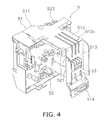
Figure 4 is a perspective view showing an electrical component unit. -
Figure 5 is a lateral view of the electrical component unit. -
Figure 6 is a view showing the electrical component unit and a partition plate. -
- 1
- Air conditioner
- 3
- Outdoor unit
- 5
- Electrical component unit
- 51
- Support member
- 52
- Electrical component
- 53
- Terminal plate
- 511
- Arrangement portion
- 512
- Protecting portion
- 513
- Lower plate-like portion
- 521
- Reactor
- 513e
- Lower end portion of the lower plate-like portion
- 511 b
- Lateral side support portion
- 511c
- Bottom end portion of the lateral side support portion
- 512c
- Groove (depression-shaped portion)
-
Figure 1 shows an air conditioner 1 including an electrical component unit 5 (seeFigure 3 and the like) according to an embodiment of the present invention. The air conditioner 1 includes anindoor unit 2 mounted in a building, anoutdoor unit 3 disposed outside, and arefrigerant pipe 4 that connects theoutdoor unit 3 to theindoor unit 2. Because the present invention relates to theelectrical component unit 5 disposed inside theoutdoor unit 3, theoutdoor unit 3 is mainly described. -
Figures 2 and3 show theoutdoor unit 3. Theoutdoor unit 3 includes acasing 31, aheat exchanger 32, acompressor 33, anair blowing unit 34, and theelectrical component unit 5. The inside of theoutdoor unit 3 is divided by apartition plate 35 into amachine space 37 where theelectrical component unit 5 and thecompressor 33 are disposed and aventilation space 36 where theheat exchanger 32, afan 343, and the like are disposed. Thepartition plate 35 is a flat plate shaped member and includes acutout 351 in a substantially rectangular shape. As shown inFigure 6 , rails 352 each having a predetermined length is provided to the upper portion of thecutout 351, and a plate-like member 354 having arectangular opening 353 is provided to the lower portion of thecutout 351. Note that theelectrical component unit 5 is described later. - The
casing 31 is a member having a substantially rectangular parallelepiped shape, and is made of sheet metal and a resin. In addition, thecasing 31 includes anair blowing port 311a and an air intake (not shown). Thecasing 31 sucks in air from the air intake and blows out the air from theair blowing port 311a. Theair blowing port 311a and the air intake are disposed on theventilation space 36 side. In addition, as shown inFigure 2 , thecasing 31 includes a casemain body 311, a caselateral wall portion 312, and aresin cover 313. The casemain body 311 is a member that covers thecompressor 33 and theheat exchanger 32. The caselateral wall portion 312 is disposed to the lateral end portion on themachine space 37 side of the case main body, and is a plate shaped member having anopening 312a. Theresin cover 313 is attached to the outside of thelateral wall portion 312, and is a plate-like member that covers a part of therefrigerant pipe 4. - As shown in
Figure 3 , theheat exchanger 32 is an L-shaped device. Theheat exchanger 32 includes afin portion 321 in which a plurality of fins are arranged in an L-shape, and apipe 322 bent several times and disposed in a supported manner by thefin portion 321. A refrigerant, such as a fluorocarbon flows through the inside of thepipe 322. - The
compressor 33 is disposed in the vicinity of thepartition plate 35 of themachine space 37, and is a machine to compress the refrigerant. It is a machine that, for example, to compress low pressure refrigerant gas into high pressure refrigerant gas. In addition, thecompressor 33 is disposed below theelectrical component unit 5. Further, thecompressor 33 includes acylindrical case 331 and devices such as a mechanism and an electric motor (not shown) for compressing the refrigerant. The devices such as the mechanism and the electric motor for compressing the refrigerant are disposed inside thecylindrical case 331. - The
air blowing unit 34 is a member disposed in theventilation space 36, and is configured to blow out air from the inside of theventilation space 36 to the outside. In addition, theair blowing unit 34 includes afan motor 341, a fan table 342, and thefan 343. Thefan motor 341 generates power to rotate thefan 343, and includes acylindrical motor portion 341a, and arotation shaft 341b rotated by thecylindrical motor portion 341a and projects from thecylindrical motor portion 341 a to theair blowing port 311 a side. The fan table 342 is a member attached to thefin portion 321, and includes a fixedportion 342a, a supportmember projecting portion 342b, and a fanmotor support portion 342c. The fixedportion 342a is a portion disposed on the upper side of theheat exchanger 32. The supportmember projecting portion 342b is a portion that projects from the fixedportion 342a to theair blowing port 311 a side. In addition, the leading end on theair blowing port 311a side of the supportmember projecting portion 342b is bent in the downward direction ofFigure 3 . Further, the supportmember projecting portion 342b has a large and substantially rectangular shaped opening in the center thereof. The fanmotor support portion 342c is a plate-like portion that extends in a vertically downward direction from the supportmember projecting portion 342b to the bottom of thecasing 31, and is a portion to which thefan motor 341 is attached. Note that, the majority of the weight of thefan motor 341, the fan table 342, and thefan 343 is supported by the bottom of thecasing 31 by the fanmotor support portion 342c. In addition, the fanmotor support portion 342c is configured such that its both ends in a direction perpendicular to the longitudinal direction are bent, thus increasing the strength compared to the case where the fan motor support portion is formed by a flat plate. Thefan 343 is a member attached to therotation shaft 341 b of thefan motor 341, and is configured to blow out air in theoutdoor unit 3 through theair blowing port 311 a. In addition, thefan 343 includes atubular portion 343a attached to therotation shaft 341b in a manner incapable of performing relative rotation and threeblade members 343b attached to the lateral surface of thetubular portion 343a. Further, thefan 343 is disposed so as to face theair blowing port 311a in order to discharge air in theventilation space 36 to the outside. - The
electrical component unit 5 is disposed above thecompressor 33, and is supported by thepartition plate 35 and thecasing 31. In addition, as shown inFigures 4 and5 , theelectrical component unit 5 includes asupport member 51, a plurality ofelectrical components 52 including areactor 521, and aterminal plate 53. - The
support member 51 is a member that supports theelectrical components 52 and theterminal plate 53, and is disposed adjacent to the top surface of thecasing 31. In addition, thesupport member 51 includes anarrangement portion 511, a projectingportion 512, and a lower plate-like portion 513. Thearrangement portion 511 is a portion that supports theelectrical components 52 other than thereactor 521, and includes: an upper plate-like portion 511a having a plate-like disposed above theelectrical components 52 other than thereactor 521; a lateralside support portion 511b disposed laterally to theelectrical components 52 other than thereactor 521; and a lowersupport plate portion 511d disposed below theelectrical components 52 other than thereactor 521. Theelectrical components 52 are disposed between the upper plate-like portion 511a and the lowersupport plate portion 511d of thearrangement portion 511. The projectingportion 512 is a plate-like portion that projects from the upper plate-like portion 511a of thearrangement portion 511 in a direction opposite to the direction where theventilation space 36 is arranged. In addition, the projectingportion 512 is a hollow member formed by bending a firstflat plate 512a projecting from the upper plate-like portion 511a such that the firstflat plate 512a is in a substantially U shape and by connecting a secondflat plate 512b to both ends of the firstflat plate 512a so as to connect the both ends. Further, threegrooves 512c are disposed in a parallel manner on the upper side surface of the projectingportion 512. The lower plate-like portion 513 is a portion extending downwardly from an end portion of the projectingportion 512, the end portion being located oppositely to another end on thearrangement portion 511 side of the projectingportion 512. The lower plate-like portion 513 includes a terminal plate attachment portion 513a, a support portion 513b, andlateral wall portions 513c. The terminal plate attachment portion 513a is a portion formed in a flat plate shape, to which theterminal plate 53 is attached. The support portion 513b is a portion disposed below the terminal plate attachment portion 513a, and is a portion supported by thecasing 31. The support portion 513b is provided with awire support portion 513d for supporting wires of theterminal plate 53. Thelateral wall portions 513c are plate-like portions outwardly extending from both lateral sides of the terminal attachment portion 513a. Note that abottom end portion 511c of the lateralside support portions 511b and alower end portion 513e of the lower plate-like portion 513 are located at substantially the same height. Here, thecasing 31 has theopening 312a at a portion corresponding to the position where the terminal plate attachment portion 513a is disposed. Theopening 312a is disposed such that a wire is passed through theopening 312a for connecting to the external power supply (seeFigure 2 ). Additionally, a shielding plate 6 made of a nonflammable resin material so as to cover theopening 312a is disposed. Accordingly, even if the inside of themachine space 37 catches fire, the impact of the fire on the outside of themachine space 37 is reduced. The shielding plate 6 is configured to support the wire connected to theterminal plate 53 and also to block between themachine space 37 side and the outside. - The plurality of
electrical components 52 are the members supported by thearrangement portion 511, and includes thereactor 521, a power transistor, a plurality of capacitors, and the like. Thereactor 521 is a substantially cubic shaped member which is attached to the projectingportion 512 of thesupport member 51. In addition, thereactor 521 is disposed with a slight distance from otherelectrical components 52.Heat radiating fins 522 are mounted to the power transistor. As shown inFigure 6 , theheat radiating fins 522 are provided as a device to transfer heat from the power transistor, and are supported by thecutout 351 of thepartition plate 35. Aninsertion opening 523 is provided in the vicinity of theheat radiating fin 522. Theinsertion opening 523 is formed between thesupport member 51 of theelectrical component unit 5 and an insertion plate 523a provided with a predetermined space from thesupport member 51. Theelectrical component unit 5 is supported by thepartition plate 35 as therails 352 of thepartition plate 35 are slid into theinsertion opening 523. Here, the insertion plate 523a is formed to extend a predetermined distance from the upper end portion of thepartition plate 35 inFigure 6 , and has the same length as therails 352 of thepartition plate 35. Accordingly, the insertion plate 523a will not cover the entire periphery of thecutout 351 of thepartition plate 35. Further, theheat radiating fin 522 has an engaging portion (not shown) at the bottom thereof that engages with therectangular opening 354 of the plate-like portion provided to thecutout 351 of thepartition plate 35. - The
terminal plate 53 is a member attached to the terminal plate attachment portion 513a of thesupport member 51, and two power supply lines and one signal line are connected to theterminal plate 53. The two power supply lines are connected to theindoor unit 2 of the air conditioner 1, and the electric power is supplied from the power supply via theindoor unit 2 of the air conditioner 1. One signal line is a line for exchanging signals with theindoor unit 2 of the air conditioner 1. - The
support member 51 of theelectrical component unit 5 includes thearrangement portion 511 that supports theelectrical components 52 and the projectingportion 512 that projects from thearrangement portion 511 toward the end portion of thecasing 31, and thereactor 521 is attached to the projectingportion 512. Accordingly, theelectrical components 52 other than thereactor 521 can be disposed at a position near thereactor 521. Accordingly, theelectrical components 52 other than thereactor 521 and thereactor 521 can be handled as one unit, which increases the design flexibility. Further, because thereactor 521 is disposed at a position away and above theelectrical components 52, theelectrical components 52 are less subject to heat generated by thereactor 521. Additionally, because theterminal plate 53 can be disposed to theelectrical component unit 5, it is possible to reduce materials for a wire and the like and lower the cost. Thebottom end portion 511c of the lateralside support portion 511b and thelower end portion 513e of the lower plate-like portion 513 are located at substantially the same height, so that theelectrical component unit 5 can be kept in the position shown inFigure 5 when placing theelectrical component unit 5 on the table or the like. In addition, workability improves because of such a structure, which thus makes it easy to perform maintenance and repairing. Because the projectingportion 512 is a hollow shaped plate member and the threegrooves 512c are formed on the upper surface of the projectingportion 512, the strength is increased, and thus even a heavy member such as thereactor 521 can be supported. Further, because thesupport member 51 is made of a fireproof material, even if theelectrical components 52 catch fire, the impact of the fire on other members can be reduced. In addition, because only a part of the insertion plate 523a is located on theventilation space 36 side with theelectrical component unit 5 supported by thepartition plate 35, even if fire occurs in themachine space 37 side, the impact of the fire on theventilation space 36 is reduced. - In the above embodiment, the lower plate-
like portion 513 to which theterminal plate 53 is disposed is attached to the end portion of the projectingportion 512. However, the present invention is not limited thereto. Theelectrical component unit 5 may be configured without the lower plate-like portion 513.
Claims (5)
- An electrical component unit (5) that houses a plurality of electrical components (52) including a specific heat generating component in an outdoor unit (3) of an air conditioner (1), the electrical component unit comprising:a support member (51) including an arrangement portion (511) in which some of the plurality of electrical components (52) can be arranged, and a projecting portion (512) outwardly projecting from the arrangement portion (511); anda reactor (521) as one of the plurality of electrical components (51), disposed away from other electrical components (52) and attached to the projecting portion (512).
- The electrical component unit (5) according to claim 1, wherein
the support member (51) further includes a lower plate-like portion (513) disposed so as to extend downwardly from a second end portion of the projecting portion (512), the second end portion being located oppositely to a first end portion on the arrangement portion (511) side of the projecting portion (512), and the lower plate-like portion being configured such that a terminal plate (53) can be arranged thereon. - The electrical component unit (5) according to claim 2, wherein
the arrangement portion (511) includes a plate-like portion (511a) disposed above the electrical components (52) other than the reactor (521), and a lateral side support portion (511b) disposed laterally to the electrical components (52) other than the reactor (521) so as to hang down from the plate-like portion (511a), and
a bottom end portion (511c) of the lateral side support portion (511b) and a lower end portion (513e) of the lower plate-like portion (513) are located at substantially the same height. - The electrical component unit according to any one of claim 1 through claim 3, wherein
the support member (51) is made of a fireproof member. - The electrical component unit according to any one of claim 1 through claim 4, wherein
the projecting portion (512) has a depression-shaped portion (512c) formed on the top surface thereof so as to extend in a projection direction of the projecting portion (512).
Applications Claiming Priority (2)
| Application Number | Priority Date | Filing Date | Title |
|---|---|---|---|
| JP2006260702A JP4533363B2 (en) | 2006-09-26 | 2006-09-26 | Electrical component unit |
| PCT/JP2007/068309 WO2008038577A1 (en) | 2006-09-26 | 2007-09-20 | Electric component unit |
Publications (2)
| Publication Number | Publication Date |
|---|---|
| EP2071250A1 true EP2071250A1 (en) | 2009-06-17 |
| EP2071250A4 EP2071250A4 (en) | 2018-03-21 |
Family
ID=39230011
Family Applications (1)
| Application Number | Title | Priority Date | Filing Date |
|---|---|---|---|
| EP07807661.9A Withdrawn EP2071250A4 (en) | 2006-09-26 | 2007-09-20 | Electric component unit |
Country Status (4)
| Country | Link |
|---|---|
| EP (1) | EP2071250A4 (en) |
| JP (1) | JP4533363B2 (en) |
| CN (1) | CN101517322B (en) |
| WO (1) | WO2008038577A1 (en) |
Cited By (3)
| Publication number | Priority date | Publication date | Assignee | Title |
|---|---|---|---|---|
| EP2985537A1 (en) * | 2014-08-04 | 2016-02-17 | Mitsubishi Electric Corporation | Heat source side unit for air conditioning apparatus |
| WO2017078512A1 (en) * | 2015-11-03 | 2017-05-11 | Daikin Research & Development Malaysia Sdn Bhd | Support panel for an outdoor unit of an air-conditioning apparatus |
| US10839675B2 (en) | 2014-12-19 | 2020-11-17 | Huawei Technologies Co., Ltd. | Anti-theft method and apparatus |
Family Cites Families (5)
| Publication number | Priority date | Publication date | Assignee | Title |
|---|---|---|---|---|
| JP3039360B2 (en) * | 1996-02-29 | 2000-05-08 | ダイキン工業株式会社 | Outdoor unit for air conditioner |
| JPH10227489A (en) * | 1997-02-13 | 1998-08-25 | Mitsubishi Electric Corp | Outdoor unit of air conditioner |
| JP2001317767A (en) * | 2000-05-09 | 2001-11-16 | Mitsubishi Electric Corp | Outdoor unit of air conditioner |
| JP2003124646A (en) * | 2001-10-10 | 2003-04-25 | Mitsubishi Heavy Ind Ltd | Electronic circuit housing case, outdoor unit, and air conditioner |
| JP4269603B2 (en) | 2002-09-04 | 2009-05-27 | ダイキン工業株式会社 | Outdoor unit electrical component unit |
-
2006
- 2006-09-26 JP JP2006260702A patent/JP4533363B2/en not_active Expired - Fee Related
-
2007
- 2007-09-20 WO PCT/JP2007/068309 patent/WO2008038577A1/en not_active Ceased
- 2007-09-20 EP EP07807661.9A patent/EP2071250A4/en not_active Withdrawn
- 2007-09-20 CN CN2007800349415A patent/CN101517322B/en active Active
Non-Patent Citations (1)
| Title |
|---|
| See references of WO2008038577A1 * |
Cited By (4)
| Publication number | Priority date | Publication date | Assignee | Title |
|---|---|---|---|---|
| EP2985537A1 (en) * | 2014-08-04 | 2016-02-17 | Mitsubishi Electric Corporation | Heat source side unit for air conditioning apparatus |
| US10839675B2 (en) | 2014-12-19 | 2020-11-17 | Huawei Technologies Co., Ltd. | Anti-theft method and apparatus |
| US10964200B2 (en) | 2014-12-19 | 2021-03-30 | Huawei Technologies Co., Ltd. | Anti-theft method and apparatus |
| WO2017078512A1 (en) * | 2015-11-03 | 2017-05-11 | Daikin Research & Development Malaysia Sdn Bhd | Support panel for an outdoor unit of an air-conditioning apparatus |
Also Published As
| Publication number | Publication date |
|---|---|
| CN101517322B (en) | 2011-07-20 |
| EP2071250A4 (en) | 2018-03-21 |
| WO2008038577A1 (en) | 2008-04-03 |
| JP2008082577A (en) | 2008-04-10 |
| JP4533363B2 (en) | 2010-09-01 |
| CN101517322A (en) | 2009-08-26 |
Similar Documents
| Publication | Publication Date | Title |
|---|---|---|
| JP5010516B2 (en) | Inverter-integrated electric compressor and its inverter device | |
| CN112702884A (en) | Integral type air source heat pump | |
| JP7012874B2 (en) | Outdoor unit of air conditioner | |
| JP5029136B2 (en) | Outdoor unit for electrical component unit and air conditioner | |
| CN101517324B (en) | Outdoor unit of air conditioner | |
| CN202792283U (en) | Outdoor unit of refrigeration device | |
| JP7112163B2 (en) | Outdoor unit of air conditioner | |
| JP6552524B2 (en) | Outdoor unit | |
| CN101517322B (en) | Electric component unit | |
| CN114857672A (en) | Wall-mounted air conditioner | |
| JP5929112B2 (en) | Air conditioner outdoor unit | |
| CN205102293U (en) | Heat source side unit of air conditioner | |
| WO2006068147A1 (en) | Outdoor machine of air conditioner | |
| JP6937937B2 (en) | Outdoor unit of air conditioner | |
| JP2009210154A (en) | Outdoor unit of air conditioner | |
| JP2009085465A (en) | Outdoor unit of air conditioner | |
| JP2006214632A (en) | Air conditioner outdoor unit | |
| KR100734484B1 (en) | Fixed Structure of Printed Circuit Board in Electric Box | |
| JPWO2020100195A1 (en) | Outdoor unit of control board and air conditioner | |
| JP5386395B2 (en) | Electric box for outdoor unit, outdoor unit and air conditioner | |
| JP2008170023A (en) | Electrical component unit | |
| JP3807353B2 (en) | Outdoor unit electrical unit and outdoor unit | |
| CN216134677U (en) | Motor control box | |
| CN1141529C (en) | Control box of air conditioner | |
| JP2010071520A (en) | Outdoor unit for air conditioner |
Legal Events
| Date | Code | Title | Description |
|---|---|---|---|
| PUAI | Public reference made under article 153(3) epc to a published international application that has entered the european phase |
Free format text: ORIGINAL CODE: 0009012 |
|
| 17P | Request for examination filed |
Effective date: 20090415 |
|
| AK | Designated contracting states |
Kind code of ref document: A1 Designated state(s): AT BE BG CH CY CZ DE DK EE ES FI FR GB GR HU IE IS IT LI LT LU LV MC MT NL PL PT RO SE SI SK TR |
|
| DAX | Request for extension of the european patent (deleted) | ||
| RA4 | Supplementary search report drawn up and despatched (corrected) |
Effective date: 20180216 |
|
| RIC1 | Information provided on ipc code assigned before grant |
Ipc: F24F 1/22 20110101AFI20180212BHEP Ipc: F24F 1/20 20110101ALI20180212BHEP Ipc: F24F 1/24 20110101ALI20180212BHEP |
|
| STAA | Information on the status of an ep patent application or granted ep patent |
Free format text: STATUS: REQUEST FOR EXAMINATION WAS MADE |
|
| STAA | Information on the status of an ep patent application or granted ep patent |
Free format text: STATUS: THE APPLICATION IS DEEMED TO BE WITHDRAWN |
|
| 18D | Application deemed to be withdrawn |
Effective date: 20180918 |