EP2071150A1 - Cooling water passage structure for engine - Google Patents
Cooling water passage structure for engine Download PDFInfo
- Publication number
- EP2071150A1 EP2071150A1 EP08018406A EP08018406A EP2071150A1 EP 2071150 A1 EP2071150 A1 EP 2071150A1 EP 08018406 A EP08018406 A EP 08018406A EP 08018406 A EP08018406 A EP 08018406A EP 2071150 A1 EP2071150 A1 EP 2071150A1
- Authority
- EP
- European Patent Office
- Prior art keywords
- cooling water
- engine
- connecting portion
- passage
- crankshaft
- Prior art date
- Legal status (The legal status is an assumption and is not a legal conclusion. Google has not performed a legal analysis and makes no representation as to the accuracy of the status listed.)
- Granted
Links
- 239000000498 cooling water Substances 0.000 title claims abstract description 220
- XLYOFNOQVPJJNP-UHFFFAOYSA-N water Substances O XLYOFNOQVPJJNP-UHFFFAOYSA-N 0.000 claims description 22
- 238000005192 partition Methods 0.000 description 8
- 238000001816 cooling Methods 0.000 description 4
- 230000001965 increasing effect Effects 0.000 description 4
- 239000000725 suspension Substances 0.000 description 4
- 230000002708 enhancing effect Effects 0.000 description 3
- 230000000694 effects Effects 0.000 description 1
- 239000002828 fuel tank Substances 0.000 description 1
- 238000012856 packing Methods 0.000 description 1
Images





Classifications
-
- F—MECHANICAL ENGINEERING; LIGHTING; HEATING; WEAPONS; BLASTING
- F01—MACHINES OR ENGINES IN GENERAL; ENGINE PLANTS IN GENERAL; STEAM ENGINES
- F01P—COOLING OF MACHINES OR ENGINES IN GENERAL; COOLING OF INTERNAL-COMBUSTION ENGINES
- F01P3/00—Liquid cooling
- F01P3/20—Cooling circuits not specific to a single part of engine or machine
-
- F—MECHANICAL ENGINEERING; LIGHTING; HEATING; WEAPONS; BLASTING
- F02—COMBUSTION ENGINES; HOT-GAS OR COMBUSTION-PRODUCT ENGINE PLANTS
- F02B—INTERNAL-COMBUSTION PISTON ENGINES; COMBUSTION ENGINES IN GENERAL
- F02B77/00—Component parts, details or accessories, not otherwise provided for
- F02B77/08—Safety, indicating, or supervising devices
- F02B77/089—Safety, indicating, or supervising devices relating to engine temperature
-
- F—MECHANICAL ENGINEERING; LIGHTING; HEATING; WEAPONS; BLASTING
- F02—COMBUSTION ENGINES; HOT-GAS OR COMBUSTION-PRODUCT ENGINE PLANTS
- F02F—CYLINDERS, PISTONS OR CASINGS, FOR COMBUSTION ENGINES; ARRANGEMENTS OF SEALINGS IN COMBUSTION ENGINES
- F02F7/00—Casings, e.g. crankcases
- F02F7/0002—Cylinder arrangements
- F02F7/0012—Crankcases of V-engines
-
- F—MECHANICAL ENGINEERING; LIGHTING; HEATING; WEAPONS; BLASTING
- F02—COMBUSTION ENGINES; HOT-GAS OR COMBUSTION-PRODUCT ENGINE PLANTS
- F02F—CYLINDERS, PISTONS OR CASINGS, FOR COMBUSTION ENGINES; ARRANGEMENTS OF SEALINGS IN COMBUSTION ENGINES
- F02F7/00—Casings, e.g. crankcases
- F02F7/0065—Shape of casings for other machine parts and purposes, e.g. utilisation purposes, safety
- F02F7/0068—Adaptations for other accessories
-
- F—MECHANICAL ENGINEERING; LIGHTING; HEATING; WEAPONS; BLASTING
- F01—MACHINES OR ENGINES IN GENERAL; ENGINE PLANTS IN GENERAL; STEAM ENGINES
- F01P—COOLING OF MACHINES OR ENGINES IN GENERAL; COOLING OF INTERNAL-COMBUSTION ENGINES
- F01P2050/00—Applications
- F01P2050/16—Motor-cycles
Definitions
- the present invention relates generally to a cooling water passage structure for an engine, and particularly for an engine mounted on a motorcycle.
- a cooling water passage structure for an engine as below.
- This structure includes cylinders arranged in a V-shape and a cylinder block having a water jacket surrounding the cylinders.
- a thermostat chamber is concavely provided in a valley portion in the upper surface of the cylinder block.
- An impeller chamber of a water pump is concavely provided at an end face of the cylinder block.
- a suction water passage connecting a bottom of the thermostat chamber with the impeller chamber, a cooling water passage connecting a water pump outlet with the water jacket, and a bypass hole communicating from the thermostat chamber to the outside are provided inside the wall body of the cylinder block.
- a warm water tube communicating from the water jacket to a radiator and a cooling water tube communicating from the radiator to the thermostat chamber are provided outside the cylinder head.
- the thermostat case is formed within the V-bank of the cylinder block. Since the cooling water line is complicatedly arranged to extend in the narrow space within the V-bank, it is difficult to improve the productivity of the engine. It is needed to simplify the cooling water passage structure.
- the invention recited in claim 1 is a cooling water passage structure for an engine, including: an engine having cylinder axes arranged in a V-shape centering on a crankshaft; water jackets formed in respective cylinder blocks and respective cylinder heads of the engine; a thermostat case having a portion formed integrally with the cylinder blocks in the V-bank of the cylinder blocks; a cooling water inlet side connecting portion connecting a cooling water supply side line with a cooling water passage including the water jackets; and a cooling water outlet side connecting portion connecting a cooling water discharge side line with a cooling water passage including the water jackets; and characterized in that the thermostat case, the cooling water inlet side connecting portion, and the cooling water outlet side connecting portion are disposed at one end side of the engine in the direction of the crankshaft.
- the invention recited in claim 2 is characterized in that, in addition to the configuration of the invention recited in claim 1, the cooling water inlet side connecting portion and the cooling water outlet side connecting portion are arranged on a centerline to align with each other as viewed from the direction of the crankshaft, the centerline dividing the V-bank of the cylinder blocks in two.
- the invention recited in claim 3 is characterized by, in addition to the configuration of the invention recited in claim 1, further including a cooling water discharge passage adapted to discharge cooling water from the water jackets to the thermostat case and in that the cooling water discharge passage is formed in the cylinder heads to extend in a direction perpendicular to the crankshaft; and in that the cooling water discharge passage and the thermostat case are arranged in a direction perpendicular to the crankshaft so as to align with each other.
- the invention recited in claim 4 is characterized by, in addition to the configuration of the invention recited in claim 1, further including a bypass line connected to an end of the thermostat case on a side separate from the crankshaft, and in that the bypass line extends toward one end of the engine in the direction of the crankshaft and connects with a water pump.
- the invention recited in claim 5 is characterized by, in addition to the configuration of the invention recited in claim 1, further including a cooling water supply passage adapted to supply cooling water from the cooling water inlet side connecting portion to the water jackets, and in that the cooling water supply passage is provided to form a protrusion on the cylinder block, and the protrusion is formed with an engine hanger used to secure the engine to a body frame.
- the invention recited in claim 6 is characterized in that, in addition to the configuration of the invention recited in claim 1, the cooling water discharge passage is formed in a V-shape as viewed from the direction of the crankshaft and the thermostat case is disposed at a central portion of the V-shape, a temperature sensor constituting a thermostat is disposed in the V-bank formed by the cooling water discharge passage and a bypass passage connecting portion is formed on the downstream side of the temperature sensor, and the cooling water discharge side connecting portion is formed in the vicinity of the top of the V-bank formed by the cooling water discharge passage.
- the thermostat case, the cooling water inlet side connecting portion, and the cooling water outlet side connecting portion are disposed at one end side of the engine in the direction of the crankshaft.
- the cooling water line is not arranged to extend in the narrow space in the V-bank.
- the cooling water passage structure can be simplified to improve the productivity of the engine.
- the space for arranging auxiliary devices therein can be ensured in the V-bank.
- the cooling water inlet side connecting portion and the cooling water outlet side connecting portion are arranged on a centerline to align with each other as viewed from the direction of the crankshaft, the centerline dividing the V-bank of the cylinder blocks in two.
- the V-bank shape of the cylinder block can effectively be utilized to make the engine compact.
- a cooling water discharge passage adapted to discharge cooling water from the water jackets to the thermostat case is provided and the cooling water discharge passage is formed in the cylinder heads to extend in a direction perpendicular to the crankshaft and the cooling water discharge passage and the thermostat case are arranged in a direction perpendicular to the crankshaft so as to align with each other.
- the partition wall between the cooling water discharge passage and the thermostat case can be shared with each other.
- the thickness of the partition wall can be reduced compared with the case where the partition wall is formed individually, thereby reducing the weight of the engine.
- the cooling water discharge passage and the thermostat case are formed to connect the V-arranged cylinder blocks and the thermostat case with each other in the back and forth direction of the vehicle.
- the rigidity of the cylinder blocks can be improved.
- the bypass line is provided which is connected to an end of the thermostat case on a side separate from the crankshaft, and the bypass line extends toward one end of the engine in the direction of the crankshaft and connects with a water pump.
- the cooling water supply passage is provided which is adapted to supply cooling water from the cooling water inlet side connecting portion to the water jackets, the cooling water supply passage is provided to form the protrusion on the cylinder block, and the protrusion is formed with an engine hanger used to secure the engine to a body frame.
- the protrusion is effectively be utilized to form the engine hanger, thereby reducing the size of the engine.
- the cooling water flowing toward the bypass line flows through the temperature sensor and the temperature sensor is disposed near a position where the direction of the flow of the cooling water from the water jackets is changed.
- the temperature of the cooling water can efficiently be transmitted to the temperature sensor, thereby enhancing the response of the temperature.
- the cooling water increased in flow rate after the warm-up operation can be led to the cooling water outlet side connecting portion in the form conforming to the direction of the flow thereof because the cooling water outlet side connecting portion is formed in the vicinity of the top of the V-bank formed by the cooling water discharge passages.
- pressure loss can be reduced to improve the efficiency of the water pump.
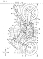
- a motorcycle 10 of the present embodiment includes a pair of left and right main frames 12 extending rearward and downward from a head pipe 11; a front fork 13 turnably supported by the head pipe 11; a front wheel FW rotatably supported by the lower end of the front fork 13; and steering handlebars 14 mounted to the upper end of the front fork 13.
- the motorcycle 10 further includes a V-type engine 50 mounted to the lower portion of the main frames 12; a swing arm 15 swingably supported by the rear portion of the engine 50; a rear wheel RW rotatably supported by the rear end of the swing arm 15; and a rear suspension 40 swingably connecting the rear portion of the main frames 12 with the lower portion of the swing arm 15.
- the motorcycle 10 further includes seat frames 16 joined to the rear upper portions of the main frames 12 and extending rearward and upward; sub frames 17 joined to the rear lower portions of the main frames 12, extending rearward and upward, and joined to the seat frames 16 at intermediate portions and at rear portions; an air cleaner box 18 and a fuel tank 19 mounted inside the main frames 12; and a seat 20 mounted on the seat frames 16.
- reference numeral 21 denotes a front cowl, 22 a side cowl, 23 a rear cowl, 24 a headlamp, 25 a tail lamp, 26 a grab rail, 27 a front fender, 28 a rear fender, 29 an exhaust pipe, and 30 a muffler.
- the rear suspension 40 includes a suspension unit 41 swingably mounted to the rear portion of the main frames 12; a generally triangular first link 42 swingably connecting the lower end of the suspension unit 41 with the lower intermediate portion of the swing arm 15; and a second link 43 swingably connecting the first link 42 with the rear portion of the engine 50.
- the engine 50 is a water-cooled V-type 4-cylinder engine and as shown in Figs. 1 and 2 includes a crankcase 51; a front cylinder block 53F and a rear cylinder block 53R; cylinder heads 54, 54; cylinder head covers 55, 55; and a cooling device 60.
- the front and rear cylinder blocks 53F, 53R are formed integrally with the upper portion of the crankcase 51 to have respective cylinder axes P arranged in a V-shape centering on the crankshaft 52.
- the cylinder heads 54, 54 are each mounted to a corresponding one of the respective upper ends of the front and rear cylinder blocks 53F, 53R.
- the cylinder head covers 55, 55 each close a corresponding one of the respective upper end openings of the cylinder head covers 55, 55.
- the cooling device 60 is used to cool the engine 50.
- the cooling device 60 mainly includes a water pump 61, a thermostat 70, water jackets 62, 63 and a radiator 64.
- the water pump 61 is disposed rearward of the crankshaft 52 of the crankcase 51.
- the thermostat 70 is disposed at the upper end of the crankcase 51 and within a V-bank of the front and rear cylinder blocks 53F, 53R.
- Water jackets 62, 63 are formed in the front and rear cylinder blocks 53F, 53R and in the cylinder heads 54, 54.
- the radiator 64 is disposed forward of the engine 50.
- reference numeral 56 in Figs. 4 to 7 denotes a cylinder bore formed in each of the front and rear cylinder blocks 53F, 53R for the respective cylinders.
- the thermostat 70 includes a thermostat case 71 disposed inside the V-bank of the front and rear cylinder blocks 53F, 53R and a thermostat valve 73 housed in a thermostat chamber 72 formed in the thermostat case 71.
- the thermostat case 71 includes a case body 74 formed integrally with the crankcase 51 and with the front and rear cylinder blocks 53F, 53R and a lid portion 75 adapted to close the upper end opening of the case body 74.
- the thermostat valve 73 includes a wax case 73a which is a temperature sensor; a plunger 73b inserted through the wax case 73a; a first valve body 73c formed at the upper end of the plunger 73b; and a second valve body 73d formed at the lower end of the plunger 73b.
- the lid portion 75 is formed with a bypass passage connecting portion 76 at a position downstream of the wax case 73a of the thermostat valve 73, i.e., at the upper end inside the lid portion 75.
- the bypass passage connecting portion 76 is joined with a bypass line 68 described later.
- a cooling water inlet side connecting portion 81 and a cooling water outlet side connecting portion 82 are provided at the upper end of the crankcase 51 and in the V-bank of the front and rear cylinder blocks 53F, 53R.
- the cooling water inlet side connecting portion 81 connects a cooling water supply side line 65 with a cooling water passage including the water jackets 62, 63.
- the cooling water outlet side connecting portion 82 connects a cooling water discharge side line 66 with a cooling water passage including the water jackets 62, 63.
- the cooling water inlet side connecting portion 81 and the cooling water outlet side connecting Portion 82 are arranged on a centerline CL so as to align with each other as viewed from the direction of the crankshaft 52.
- they are formed integrally with the crankcase 51 and with the front and rear cylinder blocks 53F, 53R.
- the centerline CL divides the V-bank of the front and rear cylinder blocks 53F, 53R in two.
- the thermostat case 71 (the thermostat 70), the cooling water inlet side connecting portion 81 and the cooling water outlet side connecting portion 82 are arranged on one end side (on the left end side in the embodiment) in the direction of the crankshaft 52 of the engine 50.
- this connection portion cover 90 is formed with a supply port 91 and with a discharge port 92.
- the supply port 91 is adapted to communicate with the cooling water inlet side connecting portion 81 and connect with the cooling water supply side line 65.
- the discharge port 92 is adapted to communicate with a cooling water outlet side connecting portion 82 and connect with a cooling water discharge side line 6.
- the connecting portion cover 90 is fastened to the engine 50 with three hexagon bolts 93.
- the connecting portion cover 90 is formed on a rear surface with a partition wall 94 separating the cooling water inlet side connecting portion 81 from the cooling water outlet side connecting portion 82.
- the connecting portion cover 90 is formed on a rear surface with a groove portion 95 extending along the outer circumferential edge portions and along the partition wall 95. A packing 96 is fitted into the groove portion 95.
- the cooling water supply side line 65 has one end connected to the discharge port of the water pump 61 and the other end connected to the supply port 91 of the connection portion cover 90.
- the cooling water discharge side line 66 has one end connected to the discharge port 92 of the connecting portion cover 90 and the other end connected to the inflow port of the radiator 64.
- One end of a cooling water return side line 67 is connected to the outflow port of the radiator 64 and the other end is connected to the suction port of the water pump 61.
- one end of the bypass pipe 68 is connected to one end of the thermostat case 71 on the side separate from the crankshaft 52, i.e., to the upper end of the lid portion 75 of the thermostat case 71.
- the other end of the bypass pipe 68 extends toward the one end side (on the left end side in the present embodiment) of the engine 50 in the direction of the crankshaft 52 and is connected to the water pump 61.
- cooling water supply passages 83, 83, cooling water discharge passages 84, 84, and a cooling water outflow passage 85 are provided at the upper end of the crankcase 51 and in the V-bank of the front and rear cylinder blocks 53F, 53R.
- the cooling water supply passages 83, 83 is adapted to supply cooling water from the cooling water inlet side connecting portion 81 to the water jackets 62, 63 on both the bank sides.
- the cooling water discharge passages 84, 84 are adapted to discharge cooling water from the water jackets 62, 63 on both the bank sides into the thermostat case 71.
- the cooling water outflow passage 85 is adapted to allow cooling water to flow from the thermostat case 71 to the cooling water outlet side connecting portion 82.
- the cooling water discharge passages 84 are each formed in a corresponding one of the front and rear cylinder blocks 53F, 53R to extend in the direction perpendicular to the crankshaft 52.
- the cooling water discharged passages 84 and the thermostat case 71 are arranged to align with each other in the direction perpendicular to the crankshaft 52.
- the front and rear cylinder blocks 53F, 53R are connected to each other in the back and forth direction of the vehicle by the cooling water discharge passage 84 and by the thermostat case 71, thereby increasing the rigidity of the front and rear cylinder blocks 53F, 53R.
- the cooling water supply passage 83 on the front bank side is provided such that the front cylinder block 53F is formed with a protrusion 57.
- the protrusion 57 is formed with an engine hanger 58 used to secure the engine 50 to the main frames 12.
- the cooling water discharge passages 84, 84 are formed in a V-shape as viewed from the direction of the crankshaft 52.
- the thermostat case 71 is disposed at the central portion of the V-shape.
- the wax case 73a of the thermostat valve 73 is disposed in the V-bank formed by the cooling water discharge passages 84, 84 and the bypass passage connecting portion 76 is formed on the downstream side of the wax case 73a.
- the wax case 73a is disposed near a position where the direction of the flow of the cooling water flowing in the thermostat chamber 72 is turned down during warm-up operation.
- the temperature of the cooling water can efficiently be transmitted to the wax case 73a, thereby enhancing the response of the wax case 73a.
- the cooling water outlet side connecting portion 82 is formed in the vicinity of the top of the V-bank formed by the cooling water discharge passages 84, 84. Even at the time of completing the warm-up operation, this allows the cooling water flowing into the thermostat chamber 72 in the V-shape to be led to the cooling water outlet side connecting portion 82 in the form conforming to the direction of the flow. Thus, pressure loss is reduced to improve the efficiency of the water pump 61.
- the cooling water inlet side connecting portion 81 connected with the cooling water supply side 65, the cooling water supply passages 83, 83 connecting the cooling water inlet side connecting portion 81 with both the water jackets 62, 63 on both the bank sides, the cooling water discharge passages 84, 84 connecting both the bank side water jackets 62, 63 with the thermostat case 71, the case body 74 of the thermostat case 71, the cooling water outflow passage 85 connecting the thermostat case 71 with the cooling water outlet side connecting portion 82, the cooling water outlet side connecting portion 82 connected with the cooling water discharge side line 66 are disposed inside the V-bank of the front and rear cylinder block 53F, 53R and formed integrally with the crankcase 51 and with the front and rear cylinder blocks 53F, 53R.
- the cooling water discharged from the water pump 61 is circulated in the following order: the cooling water supply side line 65 ⁇ the cooling water inlet side connecting portion 81 ⁇ the cooling water supply passages 83, 83 ⁇ the water jackets 62, 63 on both the bank sides ⁇ the cooling water discharge passages 84, 84 ⁇ the thermostat chamber 72 ⁇ the bypass passage connecting portion 76 ⁇ the bypass line 68 ⁇ the water pump 61.
- the cooling water is circulated in the following order: the cooling water supply side line 65 ⁇ the cooling water inlet side connecting portion 81 ⁇ the cooling water supply passages 83, 83 ⁇ the water jackets 62, 63 on both the bank sides ⁇ the cooling water discharge passages 84, 84 ⁇ the thermostat chamber 72 ⁇ the cooling water outflow passage 85 ⁇ the cooling water outlet side connecting portion 82 ⁇ the cooling water discharge side line 66 ⁇ the radiator 64 ⁇ the cooling water return side line 67 ⁇ the water pump 61.
- the thermostat case 71, the cooling water inlet side connecting portion 81 and the cooling water outlet side connecting portion 82 are disposed on one end side of the engine 50 in the direction of the crankshaft 52. Therefore, the cooling water line is not arranged to extend in the narrow space within the V-bank.
- the cooling water passage structure can be simplified to enhance the productivity of the engine.
- a space adapted to arrange auxiliary machines therein can be ensured in the V-bank.
- the cooling water inlet side connecting portion 81 and the cooling water outlet side connecting portion 82 are arranged to align with each other on the centerline CL as viewed from the direction of the crankshaft 52, the centerline CL dividing the V-bank of the front and rear cylinder blocks 53F, 53R in two.
- the V-bank shape of the front and rear cylinder blocks 53F, 53R can effectively be utilized.
- the engine 50 can be made compact.
- the engine cooling water passage structure of the present embodiment is provided with the cooling water discharge passages 84, 84 each adapted to discharge cooling water from a corresponding one of the water jackets 62, 63 to the thermostat case 71.
- the cooling water discharge passages 84, 84 are each formed in a corresponding one of the front and rear cylinder blocks 53F, 53R so as to extend along the direction perpendicular to the crankshaft 52.
- the cooling water discharge passages 84, 84 and the thermostat case 71 are arranged to align with each other in the direction perpendicular to the crankshaft 52.
- the partition wall between one of the cooling water discharge passages 84, 84 and the thermostat case 71 and between the other and the thermostat case 71 can be shared with each other.
- the thickness of the partition wall can be reduced compared with the case where the partition wall is individually formed, thereby reducing the weight of the engine 50.
- the cooling water discharge passages 84, 84 and the thermostat case 71 are formed to connect the V-arranged front and rear cylinder blocks 53F, 53R with each other in the back and forth direction of the vehicle.
- the rigidity of the front and rear cylinder blocks 53F, 53R can be increased.
- the bypass line 68 connected to the end of the thermostat case 71 on the side separate from the crankshaft 52.
- the bypass line 68 extends toward one end of the engine 50 in the direction of the crankshaft 52 and connects with the water pump 61. All the cooling water lines 65, 66, 67, 68 can be put together on one side of the engine 50. Thus, the cooling lines 65, 66, 67, 68 can easily be checked. In addition, the space within the V-bank can be ensured.
- the engine cooling water passage structure of the present embodiment is provided with the cooling water supply passages 83, 83 adapted to supply cooling water from the cooling water inlet side connecting portion 81 to the water jackets 62, 63.
- the cooling water supply passage 83 is provided to form the protrusion 57 on the front cylinder block 53F.
- the protrusion 57 is formed with the engine hanger 58 used to secure the engine 50 to the main frames 12.
- the protrusion 57 can effectively be utilized to form the engine hanger 58, thereby reducing the weight of the engine 50.
- the cooling water flowing toward the bypass line flows through the wax case 73a and the wax case 73a is disposed near a position where the direction of the flow of the cooling water from the water jackets 62, 63 is changed.
- the temperature of the cooling water can efficiently be transmitted to the wax case 73a, thereby enhancing the response of the wax case 73a.
- the cooling water increased in flow rate after the warm-up operation can be led to the cooling water outlet side connecting portion 82 in the form conforming to the direction of the flow thereof because the cooling water outlet side connecting portion 82 is formed in the vicinity of the top of the V-bank formed by the cooling water discharge passages 84, 84.
- pressure loss is reduced to improve the efficiency of the water pump 61.
- the present invention is directed to provide a cooling water passage structure for an engine that can be simplified and improve the productivity of the engine.
- a cooling water passage structure includes an engine 50 having cylinder axes P arranged in a V-shape centering on a crankshaft 52; water jackets 62, 63 formed in front and rear cylinder blocks 53 F, 53R and cylinder heads 54, 54 of the engine 50; a thermostat case 71 having a portion formed integrally with the front and rear cylinder blocks 53F, 53R in the V-bank of the front and rear cylinder blocks 53F, 53R; a cooling water inlet side connecting portion 81 connecting a cooling water supply side line 65 with a cooling water passage including the water jackets 62, 63; and a cooling water outlet side connecting portion 82 connecting a cooling water discharge side line 66 with a cooling water passage including the water jackets 62, 63.
- the thermostat case 71, the cooling water inlet side connecting portion 81, and the cooling water outlet side connecting portion 82 are disposed at one end side of the engine 50 in the direction of the crankshaft 52.
Landscapes
- Engineering & Computer Science (AREA)
- Chemical & Material Sciences (AREA)
- Combustion & Propulsion (AREA)
- Mechanical Engineering (AREA)
- General Engineering & Computer Science (AREA)
- Cylinder Crankcases Of Internal Combustion Engines (AREA)
Abstract
Description
- The present invention relates generally to a cooling water passage structure for an engine, and particularly for an engine mounted on a motorcycle.
- In related art, there is known a cooling water passage structure for an engine as below. This structure includes cylinders arranged in a V-shape and a cylinder block having a water jacket surrounding the cylinders. A thermostat chamber is concavely provided in a valley portion in the upper surface of the cylinder block. An impeller chamber of a water pump is concavely provided at an end face of the cylinder block. A suction water passage connecting a bottom of the thermostat chamber with the impeller chamber, a cooling water passage connecting a water pump outlet with the water jacket, and a bypass hole communicating from the thermostat chamber to the outside are provided inside the wall body of the cylinder block. A warm water tube communicating from the water jacket to a radiator and a cooling water tube communicating from the radiator to the thermostat chamber are provided outside the cylinder head. (See e.g. Japanese utility model No.
JP-U-2-139325 - Incidentally, in the engine cooling water passage structure described in
JP-U-2-139325 - In view of the foregoing, it is an object of the present invention to provide a cooling water passage structure for an engine that can be simplified and improve the productivity of the engine.
- To achieve the above problem, the invention recited in claim 1 is a cooling water passage structure for an engine, including: an engine having cylinder axes arranged in a V-shape centering on a crankshaft; water jackets formed in respective cylinder blocks and respective cylinder heads of the engine; a thermostat case having a portion formed integrally with the cylinder blocks in the V-bank of the cylinder blocks; a cooling water inlet side connecting portion connecting a cooling water supply side line with a cooling water passage including the water jackets; and a cooling water outlet side connecting portion connecting a cooling water discharge side line with a cooling water passage including the water jackets; and characterized in that the thermostat case, the cooling water inlet side connecting portion, and the cooling water outlet side connecting portion are disposed at one end side of the engine in the direction of the crankshaft.
- The invention recited in claim 2 is characterized in that, in addition to the configuration of the invention recited in claim 1, the cooling water inlet side connecting portion and the cooling water outlet side connecting portion are arranged on a centerline to align with each other as viewed from the direction of the crankshaft, the centerline dividing the V-bank of the cylinder blocks in two.
- The invention recited in claim 3 is characterized by, in addition to the configuration of the invention recited in claim 1, further including a cooling water discharge passage adapted to discharge cooling water from the water jackets to the thermostat case and in that the cooling water discharge passage is formed in the cylinder heads to extend in a direction perpendicular to the crankshaft; and in that the cooling water discharge passage and the thermostat case are arranged in a direction perpendicular to the crankshaft so as to align with each other.
- The invention recited in
claim 4 is characterized by, in addition to the configuration of the invention recited in claim 1, further including a bypass line connected to an end of the thermostat case on a side separate from the crankshaft, and in that the bypass line extends toward one end of the engine in the direction of the crankshaft and connects with a water pump. - The invention recited in claim 5 is characterized by, in addition to the configuration of the invention recited in claim 1, further including a cooling water supply passage adapted to supply cooling water from the cooling water inlet side connecting portion to the water jackets, and in that the cooling water supply passage is provided to form a protrusion on the cylinder block, and the protrusion is formed with an engine hanger used to secure the engine to a body frame.
- The invention recited in claim 6 is characterized in that, in addition to the configuration of the invention recited in claim 1, the cooling water discharge passage is formed in a V-shape as viewed from the direction of the crankshaft and the thermostat case is disposed at a central portion of the V-shape, a temperature sensor constituting a thermostat is disposed in the V-bank formed by the cooling water discharge passage and a bypass passage connecting portion is formed on the downstream side of the temperature sensor, and the cooling water discharge side connecting portion is formed in the vicinity of the top of the V-bank formed by the cooling water discharge passage.
- According to the cooling water passage structure for an engine recited in claim 1, the thermostat case, the cooling water inlet side connecting portion, and the cooling water outlet side connecting portion are disposed at one end side of the engine in the direction of the crankshaft. The cooling water line is not arranged to extend in the narrow space in the V-bank.
Thus, the cooling water passage structure can be simplified to improve the productivity of the engine. In addition, the space for arranging auxiliary devices therein can be ensured in the V-bank. - According to the cooling water passage structure for an engine recited in claim 2, the cooling water inlet side connecting portion and the cooling water outlet side connecting portion are arranged on a centerline to align with each other as viewed from the direction of the crankshaft, the centerline dividing the V-bank of the cylinder blocks in two. Thus, the V-bank shape of the cylinder block can effectively be utilized to make the engine compact.
- According to the cooling water passage structure for an engine recited in claim 3, a cooling water discharge passage adapted to discharge cooling water from the water jackets to the thermostat case is provided and the cooling water discharge passage is formed in the cylinder heads to extend in a direction perpendicular to the crankshaft and the cooling water discharge passage and the thermostat case are arranged in a direction perpendicular to the crankshaft so as to align with each other. The partition wall between the cooling water discharge passage and the thermostat case can be shared with each other. Thus, the thickness of the partition wall can be reduced compared with the case where the partition wall is formed individually, thereby reducing the weight of the engine. In addition, the cooling water discharge passage and the thermostat case are formed to connect the V-arranged cylinder blocks and the thermostat case with each other in the back and forth direction of the vehicle. Thus, the rigidity of the cylinder blocks can be improved.
- According to the cooling water passage structure for an engine recited in
claim 4, the bypass line is provided which is connected to an end of the thermostat case on a side separate from the crankshaft, and the bypass line extends toward one end of the engine in the direction of the crankshaft and connects with a water pump. Thus, all the cooling water lines can be put together on one side of the engine, so that it is easy to check the cooling water lines. In addition, the space in the V-bank can be ensured. - According to the cooling water passage structure for an engine recited in claim 5, the cooling water supply passage is provided which is adapted to supply cooling water from the cooling water inlet side connecting portion to the water jackets, the cooling water supply passage is provided to form the protrusion on the cylinder block, and the protrusion is formed with an engine hanger used to secure the engine to a body frame. Thus, the protrusion is effectively be utilized to form the engine hanger, thereby reducing the size of the engine.
- According to the cooling water passage structure for an engine recited in claim 6, during warm-up operation, the cooling water flowing toward the bypass line flows through the temperature sensor and the temperature sensor is disposed near a position where the direction of the flow of the cooling water from the water jackets is changed. Thus, the temperature of the cooling water can efficiently be transmitted to the temperature sensor, thereby enhancing the response of the temperature. At the time of completing the warm-up operation, the cooling water increased in flow rate after the warm-up operation can be led to the cooling water outlet side connecting portion in the form conforming to the direction of the flow thereof because the cooling water outlet side connecting portion is formed in the vicinity of the top of the V-bank formed by the cooling water discharge passages. Thus, pressure loss can be reduced to improve the efficiency of the water pump.
-
-
Fig. 1 is a lateral view illustrating the entire configuration of a motorcycle on which a cooling water passage structure for an engine according to the present invention is mounted. -
Fig. 2 is an enlarged lateral view of an essential portion for assistance in explaining the engine cooling water passage structure according to the present invention. -
Fig. 3 is an enlarged lateral view of the essential portion with a lid portion and a connection portion cover of a thermostat case in the engine shown inFig. 2 being removed. -
Fig. 4 is an enlarged plan view of the essential portion of the engine shown inFig. 2 . -
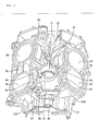
Fig. 5 is a perspective view of the cylinder block shown inFig. 2 with a cylinder head removed. -
Fig. 6 is a cross-sectional view taken along line A-A ofFig. 4 . -
Fig. 7 is a cross-sectional view taken along line B-B ofFig. 4 . -
Fig. 8 is a cross-sectional view taken along line C-C ofFig. 4 . -
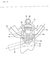
Fig. 9 is a plan view illustrating a cooling water inlet side connecting portion, a cooling water supply passage, water jackets, cooling water discharge passages, and a cooling water outlet side connecting portion in a visualized state. -
Fig. 10 is a lateral view illustrating the cooling water discharge passage, a thermostat chamber, a bypass passage connecting portion, and the cooling water outlet side connecting portion in a visualized state. -
Fig. 11 illustrates the front surface of a connecting portion cover as a single piece. -
Fig. 12 illustrates the rear surface of the connecting portion cover as a single piece. - An embodiment of a cooling water passage structure for an engine according to the present invention will hereinafter be described in detail with reference to the accompanying drawings. It is to be noted that the drawings shall be viewed based on the orientation of referential symbols.
- It is to be noted that in the following description the front and back or rear, the left and right, the upside and downside are based on the direction a rider looks and the front is indicated with Fr, the rear Rr, the left side L, the right side R, the upside U and the downside D.
- With reference to
Fig. 1 , amotorcycle 10 of the present embodiment includes a pair of left and right main frames 12 extending rearward and downward from ahead pipe 11; afront fork 13 turnably supported by thehead pipe 11; a front wheel FW rotatably supported by the lower end of thefront fork 13; andsteering handlebars 14 mounted to the upper end of thefront fork 13. Themotorcycle 10 further includes a V-type engine 50 mounted to the lower portion of the main frames 12; aswing arm 15 swingably supported by the rear portion of theengine 50; a rear wheel RW rotatably supported by the rear end of theswing arm 15; and arear suspension 40 swingably connecting the rear portion of the main frames 12 with the lower portion of theswing arm 15. Themotorcycle 10 further includesseat frames 16 joined to the rear upper portions of the main frames 12 and extending rearward and upward;sub frames 17 joined to the rear lower portions of the main frames 12, extending rearward and upward, and joined to theseat frames 16 at intermediate portions and at rear portions; anair cleaner box 18 and afuel tank 19 mounted inside the main frames 12; and aseat 20 mounted on theseat frames 16. - In
Fig. 1 ,reference numeral 21 denotes a front cowl, 22 a side cowl, 23 a rear cowl, 24 a headlamp, 25 a tail lamp, 26 a grab rail, 27 a front fender, 28 a rear fender, 29 an exhaust pipe, and 30 a muffler. - The
rear suspension 40 includes asuspension unit 41 swingably mounted to the rear portion of the main frames 12; a generally triangularfirst link 42 swingably connecting the lower end of thesuspension unit 41 with the lower intermediate portion of theswing arm 15; and asecond link 43 swingably connecting thefirst link 42 with the rear portion of theengine 50. - The
engine 50 is a water-cooled V-type 4-cylinder engine and as shown inFigs. 1 and2 includes acrankcase 51; afront cylinder block 53F and arear cylinder block 53R;cylinder heads cooling device 60. The front andrear cylinder blocks crankcase 51 to have respective cylinder axes P arranged in a V-shape centering on thecrankshaft 52. The cylinder heads 54, 54 are each mounted to a corresponding one of the respective upper ends of the front andrear cylinder blocks cooling device 60 is used to cool theengine 50. - With reference to
Figs. 1 and4 to 7 , thecooling device 60 mainly includes awater pump 61, athermostat 70,water jackets radiator 64. Thewater pump 61 is disposed rearward of thecrankshaft 52 of thecrankcase 51. Thethermostat 70 is disposed at the upper end of thecrankcase 51 and within a V-bank of the front andrear cylinder blocks Water jackets rear cylinder blocks radiator 64 is disposed forward of theengine 50. Incidentally,reference numeral 56 inFigs. 4 to 7 denotes a cylinder bore formed in each of the front andrear cylinder blocks - With reference to
Figs. 7 to 10 , thethermostat 70 includes athermostat case 71 disposed inside the V-bank of the front andrear cylinder blocks thermostat valve 73 housed in athermostat chamber 72 formed in thethermostat case 71. Thethermostat case 71 includes acase body 74 formed integrally with thecrankcase 51 and with the front andrear cylinder blocks lid portion 75 adapted to close the upper end opening of thecase body 74. - The
thermostat valve 73 includes awax case 73a which is a temperature sensor; aplunger 73b inserted through thewax case 73a; afirst valve body 73c formed at the upper end of theplunger 73b; and asecond valve body 73d formed at the lower end of theplunger 73b. - As shown in
Fig. 10 , thelid portion 75 is formed with a bypasspassage connecting portion 76 at a position downstream of thewax case 73a of thethermostat valve 73, i.e., at the upper end inside thelid portion 75. The bypasspassage connecting portion 76 is joined with abypass line 68 described later. - As shown in
Figs. 2 and3 , in the present embodiment, a cooling water inletside connecting portion 81 and a cooling water outletside connecting portion 82 are provided at the upper end of thecrankcase 51 and in the V-bank of the front andrear cylinder blocks side connecting portion 81 connects a cooling watersupply side line 65 with a cooling water passage including thewater jackets side connecting portion 82 connects a cooling waterdischarge side line 66 with a cooling water passage including thewater jackets - As shown in
Fig. 3 , the cooling water inletside connecting portion 81 and the cooling water outletside connecting Portion 82 are arranged on a centerline CL so as to align with each other as viewed from the direction of thecrankshaft 52. In addition, they are formed integrally with thecrankcase 51 and with the front andrear cylinder blocks rear cylinder blocks - In the present embodiment, the thermostat case 71 (the thermostat 70), the cooling water inlet
side connecting portion 81 and the cooling water outletside connecting portion 82 are arranged on one end side (on the left end side in the embodiment) in the direction of thecrankshaft 52 of theengine 50. - As shown in
Fig. 2 , the left end opening of the cooling water inletside connecting portion 81 and of the cooling water outletside connecting portion 82 is closed by a connectingportion cover 90. As shown inFigs. 11 and 12 , thisconnection portion cover 90 is formed with asupply port 91 and with adischarge port 92. Thesupply port 91 is adapted to communicate with the cooling water inletside connecting portion 81 and connect with the cooling watersupply side line 65. Thedischarge port 92 is adapted to communicate with a cooling water outletside connecting portion 82 and connect with a cooling water discharge side line 6. The connectingportion cover 90 is fastened to theengine 50 with threehexagon bolts 93. In addition, the connectingportion cover 90 is formed on a rear surface with apartition wall 94 separating the cooling water inletside connecting portion 81 from the cooling water outletside connecting portion 82. The connectingportion cover 90 is formed on a rear surface with agroove portion 95 extending along the outer circumferential edge portions and along thepartition wall 95. A packing 96 is fitted into thegroove portion 95. - As shown in
Figs. 1 and2 , the cooling watersupply side line 65 has one end connected to the discharge port of thewater pump 61 and the other end connected to thesupply port 91 of theconnection portion cover 90. The cooling waterdischarge side line 66 has one end connected to thedischarge port 92 of the connectingportion cover 90 and the other end connected to the inflow port of theradiator 64. One end of a cooling waterreturn side line 67 is connected to the outflow port of theradiator 64 and the other end is connected to the suction port of thewater pump 61. - In the present embodiment, one end of the
bypass pipe 68 is connected to one end of thethermostat case 71 on the side separate from thecrankshaft 52, i.e., to the upper end of thelid portion 75 of thethermostat case 71. The other end of thebypass pipe 68 extends toward the one end side (on the left end side in the present embodiment) of theengine 50 in the direction of thecrankshaft 52 and is connected to thewater pump 61. - As shown in
Figs. 4 to 8 , in the present embodiment, coolingwater supply passages water discharge passages water outflow passage 85 are provided at the upper end of thecrankcase 51 and in the V-bank of the front andrear cylinder blocks water supply passages side connecting portion 81 to thewater jackets water discharge passages water jackets thermostat case 71. The coolingwater outflow passage 85 is adapted to allow cooling water to flow from thethermostat case 71 to the cooling water outletside connecting portion 82. - As shown in
Figs. 4 and7 , in the present embodiment, the coolingwater discharge passages 84 are each formed in a corresponding one of the front andrear cylinder blocks crankshaft 52. The cooling water dischargedpassages 84 and thethermostat case 71 are arranged to align with each other in the direction perpendicular to thecrankshaft 52. Thus, the front andrear cylinder blocks water discharge passage 84 and by thethermostat case 71, thereby increasing the rigidity of the front andrear cylinder blocks - As shown in
Figs. 2 to 5 , in the present embodiment, the coolingwater supply passage 83 on the front bank side is provided such that thefront cylinder block 53F is formed with aprotrusion 57. Theprotrusion 57 is formed with anengine hanger 58 used to secure theengine 50 to the main frames 12. - As shown in
Figs. 7 and10 , in the present embodiment, the coolingwater discharge passages crankshaft 52. In addition, thethermostat case 71 is disposed at the central portion of the V-shape. Thewax case 73a of thethermostat valve 73 is disposed in the V-bank formed by the coolingwater discharge passages passage connecting portion 76 is formed on the downstream side of thewax case 73a. In this way, thewax case 73a is disposed near a position where the direction of the flow of the cooling water flowing in thethermostat chamber 72 is turned down during warm-up operation. Thus, the temperature of the cooling water can efficiently be transmitted to thewax case 73a, thereby enhancing the response of thewax case 73a. - In the present embodiment, as shown in
Figs. 7 and10 , the cooling water outletside connecting portion 82 is formed in the vicinity of the top of the V-bank formed by the coolingwater discharge passages thermostat chamber 72 in the V-shape to be led to the cooling water outletside connecting portion 82 in the form conforming to the direction of the flow. Thus, pressure loss is reduced to improve the efficiency of thewater pump 61. - In the engine cooling water passage structure configured as above, as shown in
Figs. 1 through 9 , the cooling water inletside connecting portion 81 connected with the coolingwater supply side 65, the coolingwater supply passages side connecting portion 81 with both thewater jackets water discharge passages side water jackets thermostat case 71, thecase body 74 of thethermostat case 71, the coolingwater outflow passage 85 connecting thethermostat case 71 with the cooling water outletside connecting portion 82, the cooling water outletside connecting portion 82 connected with the cooling waterdischarge side line 66 are disposed inside the V-bank of the front andrear cylinder block crankcase 51 and with the front andrear cylinder blocks - In this way, during warm-up operation, since the
first valve body 73c of thethermostat valve 73 is opened and thesecond valve body 73d is closed (see the solid lines inFig. 10 ), the cooling water discharged from thewater pump 61 is circulated in the following order: the cooling watersupply side line 65 → the cooling water inletside connecting portion 81 → the coolingwater supply passages water jackets water discharge passages thermostat chamber 72 → the bypasspassage connecting portion 76 → thebypass line 68 → thewater pump 61. At the time of completing the warm-up operation, since thefirst valve body 73c of thethermostat valve 73 is closed and thesecond valve body 73d is opened (see the chain lines inFig. 10 ), the cooling water is circulated in the following order: the cooling watersupply side line 65 → the cooling water inletside connecting portion 81 → the coolingwater supply passages water jackets water discharge passages thermostat chamber 72 → the coolingwater outflow passage 85 → the cooling water outletside connecting portion 82 → the cooling waterdischarge side line 66 → theradiator 64 → the cooling waterreturn side line 67 → thewater pump 61. - As described above, according to the engine cooling water passage structure of the present embodiment, the
thermostat case 71, the cooling water inletside connecting portion 81 and the cooling water outletside connecting portion 82 are disposed on one end side of theengine 50 in the direction of thecrankshaft 52. Therefore, the cooling water line is not arranged to extend in the narrow space within the V-bank. Thus, the cooling water passage structure can be simplified to enhance the productivity of the engine. In addition, a space adapted to arrange auxiliary machines therein can be ensured in the V-bank. - According to the engine cooling water passage structure, the cooling water inlet
side connecting portion 81 and the cooling water outletside connecting portion 82 are arranged to align with each other on the centerline CL as viewed from the direction of thecrankshaft 52, the centerline CL dividing the V-bank of the front andrear cylinder blocks rear cylinder blocks engine 50 can be made compact. - The engine cooling water passage structure of the present embodiment is provided with the cooling
water discharge passages water jackets thermostat case 71. The coolingwater discharge passages rear cylinder blocks crankshaft 52. The coolingwater discharge passages thermostat case 71 are arranged to align with each other in the direction perpendicular to thecrankshaft 52. The partition wall between one of the coolingwater discharge passages thermostat case 71 and between the other and thethermostat case 71 can be shared with each other. Thus, the thickness of the partition wall can be reduced compared with the case where the partition wall is individually formed, thereby reducing the weight of theengine 50. In addition, the coolingwater discharge passages thermostat case 71 are formed to connect the V-arranged front andrear cylinder blocks rear cylinder blocks - According to the engine cooling water passage structure of the present embodiment is provided with the
bypass line 68 connected to the end of thethermostat case 71 on the side separate from thecrankshaft 52. Thebypass line 68 extends toward one end of theengine 50 in the direction of thecrankshaft 52 and connects with thewater pump 61. All the coolingwater lines engine 50. Thus, thecooling lines - The engine cooling water passage structure of the present embodiment is provided with the cooling
water supply passages side connecting portion 81 to thewater jackets water supply passage 83 is provided to form theprotrusion 57 on thefront cylinder block 53F. Theprotrusion 57 is formed with theengine hanger 58 used to secure theengine 50 to the main frames 12. Thus, theprotrusion 57 can effectively be utilized to form theengine hanger 58, thereby reducing the weight of theengine 50. - According to the engine cooling water passage structure of the present embodiment, during warm-up operation, the cooling water flowing toward the bypass line flows through the
wax case 73a and thewax case 73a is disposed near a position where the direction of the flow of the cooling water from thewater jackets wax case 73a, thereby enhancing the response of thewax case 73a. At the time of completing the warm-up operation, the cooling water increased in flow rate after the warm-up operation can be led to the cooling water outletside connecting portion 82 in the form conforming to the direction of the flow thereof because the cooling water outletside connecting portion 82 is formed in the vicinity of the top of the V-bank formed by the coolingwater discharge passages water pump 61. - The present invention is directed to provide a cooling water passage structure for an engine that can be simplified and improve the productivity of the engine.
- A cooling water passage structure includes an
engine 50 having cylinder axes P arranged in a V-shape centering on acrankshaft 52;water jackets rear cylinder blocks cylinder heads engine 50; athermostat case 71 having a portion formed integrally with the front andrear cylinder blocks rear cylinder blocks side connecting portion 81 connecting a cooling watersupply side line 65 with a cooling water passage including thewater jackets side connecting portion 82 connecting a cooling waterdischarge side line 66 with a cooling water passage including thewater jackets thermostat case 71, the cooling water inletside connecting portion 81, and the cooling water outletside connecting portion 82 are disposed at one end side of theengine 50 in the direction of thecrankshaft 52.
Claims (6)
- A cooling water passage structure for an engine (50), comprising:an engine (50) having cylinder axes (P) arranged in a V-shape centering on a crankshaft (52);water jackets (62, 63) formed in respective cylinder blocks (53R, 53R) and respective cylinder heads (54) of the engine (50);a thermostat case (71) having a portion formed integrally with the cylinder blocks (53F, 53R) in the V-bank of the cylinder blocks (53F, 53R);a cooling water inlet side connecting portion (81) connecting a cooling water supply side line (65) with a cooling water passage including the water jackets (62, 63); anda cooling water outlet side connecting portion (82) connecting a cooling water discharge side line (66) with a cooling water passage including the water jackets (62, 63);wherein the thermostat case (71), the cooling water inlet side connecting portion (81), and the cooling water outlet side connecting portion (82) are disposed at one end side of the engine (50) in the direction of the crankshaft (52).
- The cooling water passage structure for an engine (50) according to claim 1, wherein the cooling water inlet side connecting portion (81) and the cooling water outlet side connecting portion (82) are arranged on a centerline (CL) to align with each other as viewed from the direction of the crankshaft (52), the centerline (CL) dividing the V-bank of the cylinder blocks (53F, 53R) in two.
- The cooling water passage structure for an engine according to any one of claims 1 or 2, further comprising
a cooling water discharge passage (84) adapted to discharge cooling water from the water jackets (62, 63) to the thermostat case (71);
wherein the cooling water discharge passage (84) is formed in the cylinder heads () to extend in a direction perpendicular to the crankshaft (52), and
the cooling water discharge passage (84) and the thermostat case (71) are arranged in a direction perpendicular to the crankshaft (52) so as to align with each other. - The cooling water passage structure for an engine (50) according to any one of claims 1 to 3, further comprising
a bypass line (68) connected to an end of the thermostat case (71) on a side separate from the crankshaft (52);
wherein the bypass line (68) extends toward one end of the engine (50) in the direction of the crankshaft (52) and connects with a water pump (61). - The cooling water passage structure for an engine (50) according
to any one of claims 1 to 4, further comprising
a cooling water supply passage (83) adapted to supply cooling water from the cooling water inlet side connecting portion (81) to the water jackets (62, 63);
wherein the cooling water supply passage (83) is provided to form a protrusion (57) on the cylinder block, and
the protrusion (57) is formed with an engine hanger (58) used to secure the engine (50) to a body frame (12). - The cooling water passage structure for an engine (50), according
to any one of claims 1 to 5, wherein
the cooling water discharge passage (84) is formed in a V-shape as viewed from the direction of the crankshaft (52) and the thermostat case (71) is disposed at a central portion of the V-shape,
a temperature sensor (73a) constituting a thermostat (70) is disposed in the V-bank formed by the cooling water discharge passage (84) and a bypass passage connecting portion (76) is formed on the downstream side of the temperature sensor (73a), and
the cooling water discharge side connecting portion is formed in the vicinity of the top of the V-bank formed by the cooling water discharge passage (84).
Applications Claiming Priority (1)
| Application Number | Priority Date | Filing Date | Title |
|---|---|---|---|
| JP2007322380A JP4858718B2 (en) | 2007-12-13 | 2007-12-13 | Engine coolant passage structure |
Publications (2)
| Publication Number | Publication Date |
|---|---|
| EP2071150A1 true EP2071150A1 (en) | 2009-06-17 |
| EP2071150B1 EP2071150B1 (en) | 2009-12-02 |
Family
ID=40010686
Family Applications (1)
| Application Number | Title | Priority Date | Filing Date |
|---|---|---|---|
| EP08018406A Ceased EP2071150B1 (en) | 2007-12-13 | 2008-10-21 | Cooling water passage structure for engine |
Country Status (5)
| Country | Link |
|---|---|
| US (1) | US8225751B2 (en) |
| EP (1) | EP2071150B1 (en) |
| JP (1) | JP4858718B2 (en) |
| DE (1) | DE602008000341D1 (en) |
| ES (1) | ES2335717T3 (en) |
Cited By (7)
| Publication number | Priority date | Publication date | Assignee | Title |
|---|---|---|---|---|
| EP2806133A1 (en) * | 2013-05-23 | 2014-11-26 | Yamaha Hatsudoki Kabushiki Kaisha | Motorcycle |
| EP2644861B1 (en) * | 2012-03-28 | 2016-05-18 | Honda Motor Co., Ltd. | Motorcycle with a cooling system structure and a water-cooled internal combustion engine |
| US10428705B2 (en) | 2017-05-15 | 2019-10-01 | Polaris Industries Inc. | Engine |
| US10550754B2 (en) | 2017-05-15 | 2020-02-04 | Polaris Industries Inc. | Engine |
| US10576817B2 (en) | 2017-05-15 | 2020-03-03 | Polaris Industries Inc. | Three-wheeled vehicle |
| US10639985B2 (en) | 2017-05-15 | 2020-05-05 | Polaris Industries Inc. | Three-wheeled vehicle |
| USD904227S1 (en) | 2018-10-26 | 2020-12-08 | Polaris Industries Inc. | Headlight of a three-wheeled vehicle |
Families Citing this family (4)
| Publication number | Priority date | Publication date | Assignee | Title |
|---|---|---|---|---|
| JP5946270B2 (en) * | 2011-12-28 | 2016-07-06 | ダイハツ工業株式会社 | Cylinder block water jacket structure |
| CN110005541A (en) * | 2018-01-05 | 2019-07-12 | 北汽福田汽车股份有限公司 | Inlet and outlet water integrated base, engine and vehicle for engine |
| WO2021025848A1 (en) | 2019-08-07 | 2021-02-11 | Laitram, L.L.C. | Roller belt with support edges |
| JP7811539B2 (en) * | 2022-12-19 | 2026-02-05 | ヤンマーホールディングス株式会社 | engine |
Citations (5)
| Publication number | Priority date | Publication date | Assignee | Title |
|---|---|---|---|---|
| US2871836A (en) * | 1956-01-18 | 1959-02-03 | Gen Motors Corp | Engine cooling system with radiator by-pass |
| JPH02139325U (en) | 1989-04-27 | 1990-11-21 | ||
| GB2249347A (en) * | 1990-10-31 | 1992-05-06 | Suzuki Motor Co | V i.c. engine cooling water pipe arrangement |
| EP0933510A2 (en) * | 1998-01-31 | 1999-08-04 | Volkswagen Aktiengesellschaft | Internal combustion engine |
| US20020195289A1 (en) * | 2001-06-21 | 2002-12-26 | Harley-Davidson Motor Company Group, Inc. | Thermostat housing assembly for liquid-cooled motorcycle engine |
Family Cites Families (12)
| Publication number | Priority date | Publication date | Assignee | Title |
|---|---|---|---|---|
| JPS5985349A (en) * | 1982-11-05 | 1984-05-17 | Showa Alum Ind Kk | Aluminum alloy for part contacting with magnetic tape |
| JPS60116055A (en) * | 1983-11-28 | 1985-06-22 | Hitachi Ltd | Data transfer method |
| JPS61291716A (en) * | 1985-06-15 | 1986-12-22 | Yanmar Diesel Engine Co Ltd | Cooling water pump connecting device for internal-combustion engine |
| JP2690968B2 (en) * | 1988-09-30 | 1997-12-17 | ヤマハ発動機株式会社 | V-type engine cooling system |
| JPH02139325A (en) * | 1988-11-12 | 1990-05-29 | Toyo Glass Co Ltd | Method for applying product label or the like |
| KR940000896Y1 (en) * | 1989-09-25 | 1994-02-21 | 마쯔다 가부시기가이샤 | Engine chiller |
| JP2503465Y2 (en) * | 1990-03-31 | 1996-07-03 | マツダ株式会社 | Engine block structure |
| JPH0830826B2 (en) * | 1990-05-14 | 1996-03-27 | シャープ株式会社 | Method for manufacturing active matrix display device |
| US5279265A (en) * | 1991-07-26 | 1994-01-18 | Nissan Motor Co., Ltd. | V-type internal combustion engine with improved water pump arrangement |
| JP3235541B2 (en) * | 1997-10-08 | 2001-12-04 | 三菱自動車工業株式会社 | V-type engine |
| JP3999340B2 (en) * | 1997-12-10 | 2007-10-31 | ヤマハ発動機株式会社 | Cylinder block structure |
| US6843209B2 (en) * | 2001-06-20 | 2005-01-18 | Honda Giken Kogyo Kabushiki Kaisha | Engine cooling water passage structure and gas/liquid separator for engine cooling system |
-
2007
- 2007-12-13 JP JP2007322380A patent/JP4858718B2/en not_active Expired - Fee Related
-
2008
- 2008-10-21 DE DE602008000341T patent/DE602008000341D1/en active Active
- 2008-10-21 ES ES08018406T patent/ES2335717T3/en active Active
- 2008-10-21 EP EP08018406A patent/EP2071150B1/en not_active Ceased
- 2008-12-04 US US12/328,311 patent/US8225751B2/en active Active
Patent Citations (5)
| Publication number | Priority date | Publication date | Assignee | Title |
|---|---|---|---|---|
| US2871836A (en) * | 1956-01-18 | 1959-02-03 | Gen Motors Corp | Engine cooling system with radiator by-pass |
| JPH02139325U (en) | 1989-04-27 | 1990-11-21 | ||
| GB2249347A (en) * | 1990-10-31 | 1992-05-06 | Suzuki Motor Co | V i.c. engine cooling water pipe arrangement |
| EP0933510A2 (en) * | 1998-01-31 | 1999-08-04 | Volkswagen Aktiengesellschaft | Internal combustion engine |
| US20020195289A1 (en) * | 2001-06-21 | 2002-12-26 | Harley-Davidson Motor Company Group, Inc. | Thermostat housing assembly for liquid-cooled motorcycle engine |
Cited By (11)
| Publication number | Priority date | Publication date | Assignee | Title |
|---|---|---|---|---|
| EP2644861B1 (en) * | 2012-03-28 | 2016-05-18 | Honda Motor Co., Ltd. | Motorcycle with a cooling system structure and a water-cooled internal combustion engine |
| EP2806133A1 (en) * | 2013-05-23 | 2014-11-26 | Yamaha Hatsudoki Kabushiki Kaisha | Motorcycle |
| US10428705B2 (en) | 2017-05-15 | 2019-10-01 | Polaris Industries Inc. | Engine |
| US10550754B2 (en) | 2017-05-15 | 2020-02-04 | Polaris Industries Inc. | Engine |
| US10576817B2 (en) | 2017-05-15 | 2020-03-03 | Polaris Industries Inc. | Three-wheeled vehicle |
| US10639985B2 (en) | 2017-05-15 | 2020-05-05 | Polaris Industries Inc. | Three-wheeled vehicle |
| US11041426B2 (en) | 2017-05-15 | 2021-06-22 | Polaris Industries Inc. | Engine |
| US11572813B2 (en) | 2017-05-15 | 2023-02-07 | Polaris Industries Inc. | Engine |
| US11614019B2 (en) | 2017-05-15 | 2023-03-28 | Polaris Industries Inc. | Engine |
| US12180878B2 (en) | 2017-05-15 | 2024-12-31 | Polaris Industries Inc. | Engine |
| USD904227S1 (en) | 2018-10-26 | 2020-12-08 | Polaris Industries Inc. | Headlight of a three-wheeled vehicle |
Also Published As
| Publication number | Publication date |
|---|---|
| JP4858718B2 (en) | 2012-01-18 |
| US20090151662A1 (en) | 2009-06-18 |
| EP2071150B1 (en) | 2009-12-02 |
| JP2009144596A (en) | 2009-07-02 |
| ES2335717T3 (en) | 2010-03-31 |
| DE602008000341D1 (en) | 2010-01-14 |
| US8225751B2 (en) | 2012-07-24 |
Similar Documents
| Publication | Publication Date | Title |
|---|---|---|
| EP2071150B1 (en) | Cooling water passage structure for engine | |
| JP5897985B2 (en) | Front wind guide structure in motorcycles | |
| CA2626401C (en) | Exhaust system for motorcycle | |
| US9080497B2 (en) | Water-cooled engine | |
| US20170284319A1 (en) | Internal combustion engine with supercharger for saddle-ride type vehicle | |
| EP2644861B1 (en) | Motorcycle with a cooling system structure and a water-cooled internal combustion engine | |
| JP2014069624A (en) | Front air guide structure of motorcycle | |
| JP4112391B2 (en) | Cylinder head of internal combustion engine | |
| JPWO2014097773A1 (en) | Saddle riding vehicle | |
| JP5841025B2 (en) | Water-cooled internal combustion engine for vehicles | |
| JP5384263B2 (en) | Vehicle air cleaner structure | |
| JP2011068250A (en) | Cylinder head cover structure of small vehicle | |
| JP6472482B2 (en) | Saddle riding | |
| JP5903263B2 (en) | Water-cooled V-type engine | |
| JP5391004B2 (en) | Vehicle air cleaner structure | |
| JP3840867B2 (en) | 4-cycle engine lubrication system | |
| EP3499006A1 (en) | Saddle-type vehicle | |
| JP5048618B2 (en) | 4-cycle air-oil cooled engine | |
| JP5926087B2 (en) | Cooling system structure in power unit for small vehicle | |
| US11053898B2 (en) | Saddle riding vehicle | |
| JP4901619B2 (en) | Breather device for internal combustion engine | |
| JP6446420B2 (en) | Saddle-type vehicle with water-cooled engine | |
| JP6665708B2 (en) | Engine oil passage structure | |
| JP3797001B2 (en) | Motorcycle engine cooling system | |
| JP2007085264A (en) | Cooling water passage for parallel multi-cylinder engine |
Legal Events
| Date | Code | Title | Description |
|---|---|---|---|
| PUAI | Public reference made under article 153(3) epc to a published international application that has entered the european phase |
Free format text: ORIGINAL CODE: 0009012 |
|
| 17P | Request for examination filed |
Effective date: 20081021 |
|
| AK | Designated contracting states |
Kind code of ref document: A1 Designated state(s): AT BE BG CH CY CZ DE DK EE ES FI FR GB GR HR HU IE IS IT LI LT LU LV MC MT NL NO PL PT RO SE SI SK TR |
|
| AX | Request for extension of the european patent |
Extension state: AL BA MK RS |
|
| GRAP | Despatch of communication of intention to grant a patent |
Free format text: ORIGINAL CODE: EPIDOSNIGR1 |
|
| GRAS | Grant fee paid |
Free format text: ORIGINAL CODE: EPIDOSNIGR3 |
|
| GRAA | (expected) grant |
Free format text: ORIGINAL CODE: 0009210 |
|
| AK | Designated contracting states |
Kind code of ref document: B1 Designated state(s): DE ES IT |
|
| REF | Corresponds to: |
Ref document number: 602008000341 Country of ref document: DE Date of ref document: 20100114 Kind code of ref document: P |
|
| AKX | Designation fees paid |
Designated state(s): DE ES IT |
|
| REG | Reference to a national code |
Ref country code: ES Ref legal event code: FG2A Ref document number: 2335717 Country of ref document: ES Kind code of ref document: T3 |
|
| PLBE | No opposition filed within time limit |
Free format text: ORIGINAL CODE: 0009261 |
|
| STAA | Information on the status of an ep patent application or granted ep patent |
Free format text: STATUS: NO OPPOSITION FILED WITHIN TIME LIMIT |
|
| 26N | No opposition filed |
Effective date: 20100903 |
|
| REG | Reference to a national code |
Ref country code: DE Ref legal event code: R084 Ref document number: 602008000341 Country of ref document: DE |
|
| PGFP | Annual fee paid to national office [announced via postgrant information from national office to epo] |
Ref country code: IT Payment date: 20181018 Year of fee payment: 11 Ref country code: ES Payment date: 20181102 Year of fee payment: 11 |
|
| PG25 | Lapsed in a contracting state [announced via postgrant information from national office to epo] |
Ref country code: IT Free format text: LAPSE BECAUSE OF NON-PAYMENT OF DUE FEES Effective date: 20191021 |
|
| PG25 | Lapsed in a contracting state [announced via postgrant information from national office to epo] |
Ref country code: ES Free format text: LAPSE BECAUSE OF NON-PAYMENT OF DUE FEES Effective date: 20191022 |
|
| PGFP | Annual fee paid to national office [announced via postgrant information from national office to epo] |
Ref country code: DE Payment date: 20210908 Year of fee payment: 14 |
|
| REG | Reference to a national code |
Ref country code: DE Ref legal event code: R119 Ref document number: 602008000341 Country of ref document: DE |
|
| PG25 | Lapsed in a contracting state [announced via postgrant information from national office to epo] |
Ref country code: DE Free format text: LAPSE BECAUSE OF NON-PAYMENT OF DUE FEES Effective date: 20230503 |