EP2070807A2 - Structural member - Google Patents
Structural member Download PDFInfo
- Publication number
- EP2070807A2 EP2070807A2 EP08020864A EP08020864A EP2070807A2 EP 2070807 A2 EP2070807 A2 EP 2070807A2 EP 08020864 A EP08020864 A EP 08020864A EP 08020864 A EP08020864 A EP 08020864A EP 2070807 A2 EP2070807 A2 EP 2070807A2
- Authority
- EP
- European Patent Office
- Prior art keywords
- accordance
- section
- brace
- strut tower
- tower brace
- Prior art date
- Legal status (The legal status is an assumption and is not a legal conclusion. Google has not performed a legal analysis and makes no representation as to the accuracy of the status listed.)
- Granted
Links
Images

Classifications
-
- B—PERFORMING OPERATIONS; TRANSPORTING
- B62—LAND VEHICLES FOR TRAVELLING OTHERWISE THAN ON RAILS
- B62D—MOTOR VEHICLES; TRAILERS
- B62D25/00—Superstructure or monocoque structure sub-units; Parts or details thereof not otherwise provided for
- B62D25/08—Front or rear portions
- B62D25/088—Details of structures as upper supports for springs or dampers
-
- B—PERFORMING OPERATIONS; TRANSPORTING
- B62—LAND VEHICLES FOR TRAVELLING OTHERWISE THAN ON RAILS
- B62D—MOTOR VEHICLES; TRAILERS
- B62D25/00—Superstructure or monocoque structure sub-units; Parts or details thereof not otherwise provided for
- B62D25/08—Front or rear portions
- B62D25/081—Cowls
-
- B—PERFORMING OPERATIONS; TRANSPORTING
- B62—LAND VEHICLES FOR TRAVELLING OTHERWISE THAN ON RAILS
- B62D—MOTOR VEHICLES; TRAILERS
- B62D29/00—Superstructures, understructures, or sub-units thereof, characterised by the material thereof
- B62D29/008—Superstructures, understructures, or sub-units thereof, characterised by the material thereof predominantly of light alloys, e.g. extruded
Definitions
- the present invention relates to a strut tower brace for a vehicle.
- This strut tower brace is made of the basis of an extruded section that is processed to its final shape.
- the extruded section is made out of aluminium or an aluminium alloy.
- JP2267083 relates to stiffening a strut tower in a vehicle towards the inner side or to the rear side by mounting a brace between the tower and a dash upper cross panel.
- the purpose of this kind of stiffening is related to crash behaviour, where the stiffening member is acting between each individual tower and their fixation in the upper cross panel.
- strut bars can be mounted to interconnect the strut towers in the car.
- braces that triangulate the strut towers with the firewall of the vehicle to increase the torsion stiffness of the vehicle.
- These components are normally made out of steel parts such as tubes that are welded together.
- welding operations include that the parts to be joined must be properly prepared and aligned before welding can start. Further, after the parts have been welded together, the parts must undergo surface finishing steps such as grinding, priming, painting etc.
- the extruded section may comprise at least one hollow chamber and a flange part, formed in a manner that gives a high stiffness in both vertical direction, as in diagonal direction. This can be achieved at a low weight, because the material is in place where it is needed for stiffening.
- the vertical stiffness is obtained due to the at least one hollow chamber, the diagonal stiffness is obtained through the combination of hollow chamber, and blank or flange part as sheer stiffener.
- the combination of an extruded hollow chamber and flange part gives a one-piece solution, which can be processed in one process line.
- the member can be made out of one extruded section or profile in an in-line stamping-, bending- forming- and deep-drawing process. This means that assembling operations can be avoided in the manufacture of the product, which gives a cost efficient solution.
- Fig. 1 discloses an extruded section 1 with a circular cross-section 2.
- a flange part 3 is integrated with the circular hollow section.
- Fig. 2 there is disclosed an extruded section 11 with a boxed cross-section 12, and an integrated flange part 13.
- the different walls in the profile may have different thicknesses t1, t2, t3, t4, t5, t6 and radii in the corners of the hollow section r1, r2, r3, r4.
- the faces of the hollow section may be convex and/or concave (not shown).
- the brace is located in the front end of the vehicle, between strut tower and firewall. It consists of at least 3 connection points (A, B, C), where point A and C are the connection points to the strut towers, and point B is to the firewall. Alternatively, point B can be attached to the frame for a windscreen in the vehicle. At point B the brace may have fixation holes 62 for fixation by bolts or the similar to a corresponding structural part in the vehicle.
- the brace consists of at least one hollow section 50 and one flange part 51. Both parts may be formed, in order to improve local stiffness.
- blank flange 51 is provided with imprints 52, 53, 54, 55 that enhance the stiffness properties of the blank part.
- the edges 56, 57 of the blank can be folded, for instance approximately perpendicular to the plane of the flange part, to further improve stiffness. Double folding of the edges may also be an alternative to enhance stiffness.
- the cross-section of the hollow section can vary over its lengthwise extension and it can further be formed or processed to improve stiffness in the area of its connection points A and C.
- the ends can be processed to represent connecting flanges 58, 59 having mounting holes 60, 61 for fixation to appropriate structural components in the vehicle.
- the brace contributes significant to an increased driving comfort of the car due to:
- the brace as so increases the eigenvalues globally and locally in the brace itself, and a significant increase in the dynamically stiffness at the connecting points.
- the strut tower brace can be formed out of all types of extrudable materials appropriate for use as structural components. Any appropriate Al-alloys that comply with the required stiffness (E-module) requirements may be applied. Preferably, cheap alloys that can be processed without difficulties can be good alternatives.
Landscapes
- Engineering & Computer Science (AREA)
- Chemical & Material Sciences (AREA)
- Combustion & Propulsion (AREA)
- Transportation (AREA)
- Mechanical Engineering (AREA)
- Architecture (AREA)
- Structural Engineering (AREA)
- Body Structure For Vehicles (AREA)
Abstract
Description
- The present invention relates to a strut tower brace for a vehicle. This strut tower brace is made of the basis of an extruded section that is processed to its final shape. Preferably the extruded section is made out of aluminium or an aluminium alloy.
-
JP2267083 - Further, there are commercial products available for aftermarket upgrade of suspension systems in cars, where strut bars can be mounted to interconnect the strut towers in the car. There are also braces that triangulate the strut towers with the firewall of the vehicle to increase the torsion stiffness of the vehicle. These components are normally made out of steel parts such as tubes that are welded together.
- The prior art solutions are relatively expensive to produce due to several assembly operations. Welding operations include that the parts to be joined must be properly prepared and aligned before welding can start. Further, after the parts have been welded together, the parts must undergo surface finishing steps such as grinding, priming, painting etc.
- In accordance with the present invention at least some of the above shortcomings can be avoided.
- In accordance with the present invention the extruded section may comprise at least one hollow chamber and a flange part, formed in a manner that gives a high stiffness in both vertical direction, as in diagonal direction. This can be achieved at a low weight, because the material is in place where it is needed for stiffening. The vertical stiffness is obtained due to the at least one hollow chamber, the diagonal stiffness is obtained through the combination of hollow chamber, and blank or flange part as sheer stiffener.
- The combination of an extruded hollow chamber and flange part gives a one-piece solution, which can be processed in one process line. The member can be made out of one extruded section or profile in an in-line stamping-, bending- forming- and deep-drawing process. This means that assembling operations can be avoided in the manufacture of the product, which gives a cost efficient solution.
- These and further advantages can be achieved by the invention as claimed in the accompanying claims.
- The present invention shall be further described by Figures and examples where;
- Fig. 1
- discloses a cross-sectional view of an extruded section with a circular cross- section,
- Fig. 2
- discloses a cross-sectional view of an extruded section with a boxed cross- section,
- Fig. 3
- discloses the cross-sectional view of the extruded section as shown in
Fig. 2 , - Fig. 4
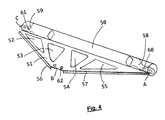
- discloses in perspective a strut tower brace in accordance with the present invention.
-
Fig. 1 discloses anextruded section 1 with acircular cross-section 2. In addition aflange part 3 is integrated with the circular hollow section. InFig. 2 there is disclosed anextruded section 11 with aboxed cross-section 12, and an integratedflange part 13. - As indicated in
Fig. 3 , the different walls in the profile may have different thicknesses t1, t2, t3, t4, t5, t6 and radii in the corners of the hollow section r1, r2, r3, r4. The faces of the hollow section may be convex and/or concave (not shown). - Local stiffness improvements are obtained to the brace by applying local deformations of the surfaces. See
Fig. 4 . - The brace is located in the front end of the vehicle, between strut tower and firewall. It consists of at least 3 connection points (A, B, C), where point A and C are the connection points to the strut towers, and point B is to the firewall. Alternatively, point B can be attached to the frame for a windscreen in the vehicle. At point B the brace may have
fixation holes 62 for fixation by bolts or the similar to a corresponding structural part in the vehicle. - The brace consists of at least one
hollow section 50 and oneflange part 51. Both parts may be formed, in order to improve local stiffness. In this embodimentblank flange 51 is provided withimprints edges - The cross-section of the hollow section can vary over its lengthwise extension and it can further be formed or processed to improve stiffness in the area of its connection points A and C. For instance, the ends can be processed to represent connecting
flanges holes - The brace contributes significant to an increased driving comfort of the car due to:
- The combination of a hollow chamber and flange part gives a stiff triangular connection between strut towers, and firewall, where the hollow chamber stiffens the vertical displacements relative between the strut towers and the blank stiffens the displacements relative between both strut towers and the firewall.
- The brace as so increases the eigenvalues globally and locally in the brace itself, and a significant increase in the dynamically stiffness at the connecting points.
- It should be understood that the strut tower brace can be formed out of all types of extrudable materials appropriate for use as structural components. Any appropriate Al-alloys that comply with the required stiffness (E-module) requirements may be applied. Preferably, cheap alloys that can be processed without difficulties can be good alternatives.
Claims (12)
- A strut tower brace for a vehicle, a stiffening member for interconnecting strut towers and one upper part of the firewall or windscreen frame in said vehicle,
characterised in that
it is made out of one extruded section or profile. - A strut tower brace in accordance with claim 1 ,
characterised in that
the extruded section consists of at least one hollow section and one flange formed part. - A strut tower brace in accordance with claim 2,
characterised in that
the hollow section may be a circular cross-section - A strut tower brace in accordance with claim 2,
characterised in that
the hollow section may be a boxed cross-section - A strut tower brace in accordance with claim 1,
characterised in that
the different walls in the section may have different thickness - A strut tower brace in accordance with claim 1,
characterised in that
it may be different radii at the corners of the section. - A strut tower brace in accordance with claim 2,
characterised in that
the faces of the hollow section or flange may be convex or concave. - A strut tower brace in accordance with claim 1,
characterised in that
the surfaces of the brace are deformed locally to improve the local stiffness of the member. - A strut tower brace in accordance with claim 8,
characterised in that
the deformation consists of imprints. - A strut tower brace in accordance with claim 8,
characterised in that
the deformation consists of edge folding. - A strut tower brace in accordance with claim 1,
characterised in that
the brace is made out of aluminium or an aluminium alloy. - A strut tower brace in accordance with claim 2,
characterised in that
the combination of an extruded hollow chamber and flange gives a high stiffness in both vertical direction, as in diagonal direction.
Applications Claiming Priority (1)
| Application Number | Priority Date | Filing Date | Title |
|---|---|---|---|
| NO20076374 | 2007-12-10 |
Publications (3)
| Publication Number | Publication Date |
|---|---|
| EP2070807A2 true EP2070807A2 (en) | 2009-06-17 |
| EP2070807A3 EP2070807A3 (en) | 2009-11-18 |
| EP2070807B1 EP2070807B1 (en) | 2011-08-03 |
Family
ID=40297732
Family Applications (1)
| Application Number | Title | Priority Date | Filing Date |
|---|---|---|---|
| EP08020864A Active EP2070807B1 (en) | 2007-12-10 | 2008-12-02 | Structural member |
Country Status (2)
| Country | Link |
|---|---|
| EP (1) | EP2070807B1 (en) |
| AT (1) | ATE518730T1 (en) |
Cited By (3)
| Publication number | Priority date | Publication date | Assignee | Title |
|---|---|---|---|---|
| JP2012081859A (en) * | 2010-10-12 | 2012-04-26 | Nissan Motor Co Ltd | Front compartment structure |
| JP2012081860A (en) * | 2010-10-12 | 2012-04-26 | Nissan Motor Co Ltd | Reinforcing cover member structure |
| US9637175B2 (en) | 2015-08-13 | 2017-05-02 | Ford Global Technologies, Llc | Extruded vehicle body component |
Families Citing this family (1)
| Publication number | Priority date | Publication date | Assignee | Title |
|---|---|---|---|---|
| US10144456B1 (en) | 2017-07-20 | 2018-12-04 | Ford Global Technologies, Llc | Strut-tower brace |
Citations (1)
| Publication number | Priority date | Publication date | Assignee | Title |
|---|---|---|---|---|
| JPH02267083A (en) | 1989-04-07 | 1990-10-31 | Nissan Motor Co Ltd | Front body reinforcement structure of automobile |
Family Cites Families (5)
| Publication number | Priority date | Publication date | Assignee | Title |
|---|---|---|---|---|
| JP3470924B2 (en) * | 1995-03-13 | 2003-11-25 | 三菱アルミニウム株式会社 | Method for manufacturing tubular member for vehicle body structure |
| US6557930B1 (en) * | 2001-10-26 | 2003-05-06 | General Motors Corporation | Multi-section support rail apparatus and method of making |
| DE102004007051B4 (en) * | 2004-02-13 | 2020-08-20 | Daimler Ag | Body for a motor vehicle |
| DE102006041110A1 (en) * | 2006-09-01 | 2007-10-18 | Audi Ag | Production of a chassis component for a vehicle comprises deep drawing and/or removing a component region of the chassis component during closing of a deforming tool |
| DE102007010821B4 (en) * | 2007-03-06 | 2016-02-04 | Audi Ag | Stiffening component for a body of a passenger car |
-
2008
- 2008-12-02 EP EP08020864A patent/EP2070807B1/en active Active
- 2008-12-02 AT AT08020864T patent/ATE518730T1/en not_active IP Right Cessation
Patent Citations (1)
| Publication number | Priority date | Publication date | Assignee | Title |
|---|---|---|---|---|
| JPH02267083A (en) | 1989-04-07 | 1990-10-31 | Nissan Motor Co Ltd | Front body reinforcement structure of automobile |
Cited By (3)
| Publication number | Priority date | Publication date | Assignee | Title |
|---|---|---|---|---|
| JP2012081859A (en) * | 2010-10-12 | 2012-04-26 | Nissan Motor Co Ltd | Front compartment structure |
| JP2012081860A (en) * | 2010-10-12 | 2012-04-26 | Nissan Motor Co Ltd | Reinforcing cover member structure |
| US9637175B2 (en) | 2015-08-13 | 2017-05-02 | Ford Global Technologies, Llc | Extruded vehicle body component |
Also Published As
| Publication number | Publication date |
|---|---|
| EP2070807B1 (en) | 2011-08-03 |
| EP2070807A3 (en) | 2009-11-18 |
| ATE518730T1 (en) | 2011-08-15 |
Similar Documents
| Publication | Publication Date | Title |
|---|---|---|
| US11560180B2 (en) | Vehicle component with multi-hollow beam | |
| US8602483B2 (en) | Vehicle door reinforcement structure | |
| US6824199B2 (en) | Fender arrangement for a motor vehicle | |
| CN102107682B (en) | Chassis structure of a motor vehicle body | |
| US8459728B2 (en) | Vehicle front portion structure | |
| JP4636799B2 (en) | Support structure made of hollow steel long section material for automobile | |
| CN103052541B (en) | The B post reinforcement of motor vehicles | |
| US6412818B1 (en) | Vehicle body and frame assembly and method of manufacturing same | |
| CN102883940B (en) | For the support unit of self-propelled vehicle | |
| US9758998B2 (en) | Motor vehicle door with hinge reinforcement | |
| JP7723182B2 (en) | Tapered rocker element | |
| US12409800B2 (en) | Bumper arrangement for a motor vehicle | |
| US20120119542A1 (en) | Car body with reinforcing structure | |
| CN108407893B (en) | Sill plate for a motor vehicle | |
| JP2005532207A5 (en) | ||
| CN104053590A (en) | Subframes for motor vehicles | |
| JP5346799B2 (en) | Body superstructure | |
| CN109311441B (en) | Bumper for a motor vehicle and method for producing said bumper | |
| US5466035A (en) | Improved vehicle front-end support structure for a passenger car | |
| US12030448B2 (en) | Bumper arrangement with additional support | |
| US20100171339A1 (en) | Support Element for a Cockpit Beam | |
| EP2070807B1 (en) | Structural member | |
| US20100327627A1 (en) | Light weight vertical support member in instrument panel frame | |
| CN219728340U (en) | Front cabin of vehicle and vehicle | |
| JP4932688B2 (en) | Roof reinforcement for automobile bodies |
Legal Events
| Date | Code | Title | Description |
|---|---|---|---|
| PUAI | Public reference made under article 153(3) epc to a published international application that has entered the european phase |
Free format text: ORIGINAL CODE: 0009012 |
|
| AK | Designated contracting states |
Kind code of ref document: A2 Designated state(s): AT BE BG CH CY CZ DE DK EE ES FI FR GB GR HR HU IE IS IT LI LT LU LV MC MT NL NO PL PT RO SE SI SK TR |
|
| AX | Request for extension of the european patent |
Extension state: AL BA MK RS |
|
| PUAL | Search report despatched |
Free format text: ORIGINAL CODE: 0009013 |
|
| AK | Designated contracting states |
Kind code of ref document: A3 Designated state(s): AT BE BG CH CY CZ DE DK EE ES FI FR GB GR HR HU IE IS IT LI LT LU LV MC MT NL NO PL PT RO SE SI SK TR |
|
| AX | Request for extension of the european patent |
Extension state: AL BA MK RS |
|
| RIC1 | Information provided on ipc code assigned before grant |
Ipc: B62D 25/08 20060101AFI20090209BHEP |
|
| RAP1 | Party data changed (applicant data changed or rights of an application transferred) |
Owner name: BENTELER AUTOMOBILTECHNIK GMBH & CO. KG |
|
| RAP1 | Party data changed (applicant data changed or rights of an application transferred) |
Owner name: BENTELER AUTOMOBILTECHNIK GMBH |
|
| 17P | Request for examination filed |
Effective date: 20100517 |
|
| AKX | Designation fees paid |
Designated state(s): AT BE BG CH CY CZ DE DK EE ES FI FR GB GR HR HU IE IS IT LI LT LU LV MC MT NL NO PL PT RO SE SI SK TR |
|
| GRAP | Despatch of communication of intention to grant a patent |
Free format text: ORIGINAL CODE: EPIDOSNIGR1 |
|
| GRAS | Grant fee paid |
Free format text: ORIGINAL CODE: EPIDOSNIGR3 |
|
| GRAA | (expected) grant |
Free format text: ORIGINAL CODE: 0009210 |
|
| AK | Designated contracting states |
Kind code of ref document: B1 Designated state(s): AT BE BG CH CY CZ DE DK EE ES FI FR GB GR HR HU IE IS IT LI LT LU LV MC MT NL NO PL PT RO SE SI SK TR |
|
| REG | Reference to a national code |
Ref country code: GB Ref legal event code: FG4D |
|
| REG | Reference to a national code |
Ref country code: CH Ref legal event code: EP |
|
| REG | Reference to a national code |
Ref country code: IE Ref legal event code: FG4D |
|
| REG | Reference to a national code |
Ref country code: DE Ref legal event code: R096 Ref document number: 602008008544 Country of ref document: DE Effective date: 20110929 |
|
| REG | Reference to a national code |
Ref country code: NL Ref legal event code: VDEP Effective date: 20110803 |
|
| LTIE | Lt: invalidation of european patent or patent extension |
Effective date: 20110803 |
|
| PG25 | Lapsed in a contracting state [announced via postgrant information from national office to epo] |
Ref country code: NL Free format text: LAPSE BECAUSE OF FAILURE TO SUBMIT A TRANSLATION OF THE DESCRIPTION OR TO PAY THE FEE WITHIN THE PRESCRIBED TIME-LIMIT Effective date: 20110803 Ref country code: HR Free format text: LAPSE BECAUSE OF FAILURE TO SUBMIT A TRANSLATION OF THE DESCRIPTION OR TO PAY THE FEE WITHIN THE PRESCRIBED TIME-LIMIT Effective date: 20110803 Ref country code: NO Free format text: LAPSE BECAUSE OF FAILURE TO SUBMIT A TRANSLATION OF THE DESCRIPTION OR TO PAY THE FEE WITHIN THE PRESCRIBED TIME-LIMIT Effective date: 20111103 Ref country code: FI Free format text: LAPSE BECAUSE OF FAILURE TO SUBMIT A TRANSLATION OF THE DESCRIPTION OR TO PAY THE FEE WITHIN THE PRESCRIBED TIME-LIMIT Effective date: 20110803 Ref country code: LT Free format text: LAPSE BECAUSE OF FAILURE TO SUBMIT A TRANSLATION OF THE DESCRIPTION OR TO PAY THE FEE WITHIN THE PRESCRIBED TIME-LIMIT Effective date: 20110803 Ref country code: SE Free format text: LAPSE BECAUSE OF FAILURE TO SUBMIT A TRANSLATION OF THE DESCRIPTION OR TO PAY THE FEE WITHIN THE PRESCRIBED TIME-LIMIT Effective date: 20110803 Ref country code: PT Free format text: LAPSE BECAUSE OF FAILURE TO SUBMIT A TRANSLATION OF THE DESCRIPTION OR TO PAY THE FEE WITHIN THE PRESCRIBED TIME-LIMIT Effective date: 20111205 Ref country code: IS Free format text: LAPSE BECAUSE OF FAILURE TO SUBMIT A TRANSLATION OF THE DESCRIPTION OR TO PAY THE FEE WITHIN THE PRESCRIBED TIME-LIMIT Effective date: 20111203 |
|
| REG | Reference to a national code |
Ref country code: AT Ref legal event code: MK05 Ref document number: 518730 Country of ref document: AT Kind code of ref document: T Effective date: 20110803 |
|
| PG25 | Lapsed in a contracting state [announced via postgrant information from national office to epo] |
Ref country code: CY Free format text: LAPSE BECAUSE OF FAILURE TO SUBMIT A TRANSLATION OF THE DESCRIPTION OR TO PAY THE FEE WITHIN THE PRESCRIBED TIME-LIMIT Effective date: 20110803 Ref country code: PL Free format text: LAPSE BECAUSE OF FAILURE TO SUBMIT A TRANSLATION OF THE DESCRIPTION OR TO PAY THE FEE WITHIN THE PRESCRIBED TIME-LIMIT Effective date: 20110803 Ref country code: AT Free format text: LAPSE BECAUSE OF FAILURE TO SUBMIT A TRANSLATION OF THE DESCRIPTION OR TO PAY THE FEE WITHIN THE PRESCRIBED TIME-LIMIT Effective date: 20110803 Ref country code: LV Free format text: LAPSE BECAUSE OF FAILURE TO SUBMIT A TRANSLATION OF THE DESCRIPTION OR TO PAY THE FEE WITHIN THE PRESCRIBED TIME-LIMIT Effective date: 20110803 Ref country code: GR Free format text: LAPSE BECAUSE OF FAILURE TO SUBMIT A TRANSLATION OF THE DESCRIPTION OR TO PAY THE FEE WITHIN THE PRESCRIBED TIME-LIMIT Effective date: 20111104 Ref country code: SI Free format text: LAPSE BECAUSE OF FAILURE TO SUBMIT A TRANSLATION OF THE DESCRIPTION OR TO PAY THE FEE WITHIN THE PRESCRIBED TIME-LIMIT Effective date: 20110803 |
|
| PG25 | Lapsed in a contracting state [announced via postgrant information from national office to epo] |
Ref country code: BE Free format text: LAPSE BECAUSE OF FAILURE TO SUBMIT A TRANSLATION OF THE DESCRIPTION OR TO PAY THE FEE WITHIN THE PRESCRIBED TIME-LIMIT Effective date: 20110803 |
|
| PG25 | Lapsed in a contracting state [announced via postgrant information from national office to epo] |
Ref country code: CZ Free format text: LAPSE BECAUSE OF FAILURE TO SUBMIT A TRANSLATION OF THE DESCRIPTION OR TO PAY THE FEE WITHIN THE PRESCRIBED TIME-LIMIT Effective date: 20110803 Ref country code: SK Free format text: LAPSE BECAUSE OF FAILURE TO SUBMIT A TRANSLATION OF THE DESCRIPTION OR TO PAY THE FEE WITHIN THE PRESCRIBED TIME-LIMIT Effective date: 20110803 |
|
| PG25 | Lapsed in a contracting state [announced via postgrant information from national office to epo] |
Ref country code: EE Free format text: LAPSE BECAUSE OF FAILURE TO SUBMIT A TRANSLATION OF THE DESCRIPTION OR TO PAY THE FEE WITHIN THE PRESCRIBED TIME-LIMIT Effective date: 20110803 Ref country code: RO Free format text: LAPSE BECAUSE OF FAILURE TO SUBMIT A TRANSLATION OF THE DESCRIPTION OR TO PAY THE FEE WITHIN THE PRESCRIBED TIME-LIMIT Effective date: 20110803 |
|
| PLBE | No opposition filed within time limit |
Free format text: ORIGINAL CODE: 0009261 |
|
| STAA | Information on the status of an ep patent application or granted ep patent |
Free format text: STATUS: NO OPPOSITION FILED WITHIN TIME LIMIT |
|
| PG25 | Lapsed in a contracting state [announced via postgrant information from national office to epo] |
Ref country code: DK Free format text: LAPSE BECAUSE OF FAILURE TO SUBMIT A TRANSLATION OF THE DESCRIPTION OR TO PAY THE FEE WITHIN THE PRESCRIBED TIME-LIMIT Effective date: 20110803 |
|
| 26N | No opposition filed |
Effective date: 20120504 |
|
| PG25 | Lapsed in a contracting state [announced via postgrant information from national office to epo] |
Ref country code: MC Free format text: LAPSE BECAUSE OF NON-PAYMENT OF DUE FEES Effective date: 20111231 |
|
| REG | Reference to a national code |
Ref country code: DE Ref legal event code: R097 Ref document number: 602008008544 Country of ref document: DE Effective date: 20120504 |
|
| REG | Reference to a national code |
Ref country code: IE Ref legal event code: MM4A |
|
| PG25 | Lapsed in a contracting state [announced via postgrant information from national office to epo] |
Ref country code: IE Free format text: LAPSE BECAUSE OF NON-PAYMENT OF DUE FEES Effective date: 20111202 |
|
| PG25 | Lapsed in a contracting state [announced via postgrant information from national office to epo] |
Ref country code: MT Free format text: LAPSE BECAUSE OF FAILURE TO SUBMIT A TRANSLATION OF THE DESCRIPTION OR TO PAY THE FEE WITHIN THE PRESCRIBED TIME-LIMIT Effective date: 20110803 |
|
| PG25 | Lapsed in a contracting state [announced via postgrant information from national office to epo] |
Ref country code: ES Free format text: LAPSE BECAUSE OF FAILURE TO SUBMIT A TRANSLATION OF THE DESCRIPTION OR TO PAY THE FEE WITHIN THE PRESCRIBED TIME-LIMIT Effective date: 20111114 |
|
| PG25 | Lapsed in a contracting state [announced via postgrant information from national office to epo] |
Ref country code: LU Free format text: LAPSE BECAUSE OF NON-PAYMENT OF DUE FEES Effective date: 20111202 |
|
| PG25 | Lapsed in a contracting state [announced via postgrant information from national office to epo] |
Ref country code: BG Free format text: LAPSE BECAUSE OF FAILURE TO SUBMIT A TRANSLATION OF THE DESCRIPTION OR TO PAY THE FEE WITHIN THE PRESCRIBED TIME-LIMIT Effective date: 20111103 |
|
| REG | Reference to a national code |
Ref country code: CH Ref legal event code: PL |
|
| GBPC | Gb: european patent ceased through non-payment of renewal fee |
Effective date: 20121202 |
|
| PG25 | Lapsed in a contracting state [announced via postgrant information from national office to epo] |
Ref country code: TR Free format text: LAPSE BECAUSE OF FAILURE TO SUBMIT A TRANSLATION OF THE DESCRIPTION OR TO PAY THE FEE WITHIN THE PRESCRIBED TIME-LIMIT Effective date: 20110803 |
|
| PG25 | Lapsed in a contracting state [announced via postgrant information from national office to epo] |
Ref country code: CH Free format text: LAPSE BECAUSE OF NON-PAYMENT OF DUE FEES Effective date: 20121231 Ref country code: HU Free format text: LAPSE BECAUSE OF FAILURE TO SUBMIT A TRANSLATION OF THE DESCRIPTION OR TO PAY THE FEE WITHIN THE PRESCRIBED TIME-LIMIT Effective date: 20110803 Ref country code: LI Free format text: LAPSE BECAUSE OF NON-PAYMENT OF DUE FEES Effective date: 20121231 |
|
| PG25 | Lapsed in a contracting state [announced via postgrant information from national office to epo] |
Ref country code: GB Free format text: LAPSE BECAUSE OF NON-PAYMENT OF DUE FEES Effective date: 20121202 |
|
| REG | Reference to a national code |
Ref country code: FR Ref legal event code: PLFP Year of fee payment: 8 |
|
| REG | Reference to a national code |
Ref country code: FR Ref legal event code: PLFP Year of fee payment: 9 |
|
| REG | Reference to a national code |
Ref country code: FR Ref legal event code: PLFP Year of fee payment: 10 |
|
| PGFP | Annual fee paid to national office [announced via postgrant information from national office to epo] |
Ref country code: IT Payment date: 20251223 Year of fee payment: 18 |
|
| PGFP | Annual fee paid to national office [announced via postgrant information from national office to epo] |
Ref country code: FR Payment date: 20251222 Year of fee payment: 18 |
|
| PGFP | Annual fee paid to national office [announced via postgrant information from national office to epo] |
Ref country code: DE Payment date: 20251219 Year of fee payment: 18 |