EP2070703A1 - Inkjet Printhead and Method of Manufacturing the Same - Google Patents
Inkjet Printhead and Method of Manufacturing the Same Download PDFInfo
- Publication number
- EP2070703A1 EP2070703A1 EP08159826A EP08159826A EP2070703A1 EP 2070703 A1 EP2070703 A1 EP 2070703A1 EP 08159826 A EP08159826 A EP 08159826A EP 08159826 A EP08159826 A EP 08159826A EP 2070703 A1 EP2070703 A1 EP 2070703A1
- Authority
- EP
- European Patent Office
- Prior art keywords
- ink
- chamber
- substrate
- adhesive portion
- inkjet printhead
- Prior art date
- Legal status (The legal status is an assumption and is not a legal conclusion. Google has not performed a legal analysis and makes no representation as to the accuracy of the status listed.)
- Withdrawn
Links
- 238000004519 manufacturing process Methods 0.000 title claims description 10
- 239000000853 adhesive Substances 0.000 claims abstract description 59
- 230000001070 adhesive effect Effects 0.000 claims abstract description 59
- 239000000758 substrate Substances 0.000 claims abstract description 46
- 229920005989 resin Polymers 0.000 claims abstract description 8
- 239000011347 resin Substances 0.000 claims abstract description 8
- 238000000034 method Methods 0.000 claims description 18
- 229920002120 photoresistant polymer Polymers 0.000 claims description 10
- KXGFMDJXCMQABM-UHFFFAOYSA-N 2-methoxy-6-methylphenol Chemical compound [CH]OC1=CC=CC([CH])=C1O KXGFMDJXCMQABM-UHFFFAOYSA-N 0.000 claims 1
- 239000005011 phenolic resin Substances 0.000 claims 1
- 229920001568 phenolic resin Polymers 0.000 claims 1
- 239000010410 layer Substances 0.000 description 48
- 239000012790 adhesive layer Substances 0.000 description 21
- 239000000463 material Substances 0.000 description 10
- 238000002161 passivation Methods 0.000 description 10
- 230000000903 blocking effect Effects 0.000 description 6
- ISWSIDIOOBJBQZ-UHFFFAOYSA-N phenol group Chemical group C1(=CC=CC=C1)O ISWSIDIOOBJBQZ-UHFFFAOYSA-N 0.000 description 4
- 238000000206 photolithography Methods 0.000 description 3
- 238000003825 pressing Methods 0.000 description 3
- 238000009835 boiling Methods 0.000 description 2
- 238000005530 etching Methods 0.000 description 2
- 239000000126 substance Substances 0.000 description 2
- 238000006243 chemical reaction Methods 0.000 description 1
- 238000001312 dry etching Methods 0.000 description 1
- 238000002474 experimental method Methods 0.000 description 1
- 230000010354 integration Effects 0.000 description 1
- 238000000059 patterning Methods 0.000 description 1
- 239000011241 protective layer Substances 0.000 description 1
- 230000035939 shock Effects 0.000 description 1
- 238000001039 wet etching Methods 0.000 description 1
Images


Classifications
-
- B—PERFORMING OPERATIONS; TRANSPORTING
- B41—PRINTING; LINING MACHINES; TYPEWRITERS; STAMPS
- B41J—TYPEWRITERS; SELECTIVE PRINTING MECHANISMS, i.e. MECHANISMS PRINTING OTHERWISE THAN FROM A FORME; CORRECTION OF TYPOGRAPHICAL ERRORS
- B41J2/00—Typewriters or selective printing mechanisms characterised by the printing or marking process for which they are designed
- B41J2/005—Typewriters or selective printing mechanisms characterised by the printing or marking process for which they are designed characterised by bringing liquid or particles selectively into contact with a printing material
- B41J2/01—Ink jet
- B41J2/135—Nozzles
- B41J2/16—Production of nozzles
- B41J2/1601—Production of bubble jet print heads
- B41J2/1603—Production of bubble jet print heads of the front shooter type
-
- B—PERFORMING OPERATIONS; TRANSPORTING
- B41—PRINTING; LINING MACHINES; TYPEWRITERS; STAMPS
- B41J—TYPEWRITERS; SELECTIVE PRINTING MECHANISMS, i.e. MECHANISMS PRINTING OTHERWISE THAN FROM A FORME; CORRECTION OF TYPOGRAPHICAL ERRORS
- B41J2/00—Typewriters or selective printing mechanisms characterised by the printing or marking process for which they are designed
- B41J2/005—Typewriters or selective printing mechanisms characterised by the printing or marking process for which they are designed characterised by bringing liquid or particles selectively into contact with a printing material
- B41J2/01—Ink jet
- B41J2/015—Ink jet characterised by the jet generation process
-
- B—PERFORMING OPERATIONS; TRANSPORTING
- B41—PRINTING; LINING MACHINES; TYPEWRITERS; STAMPS
- B41J—TYPEWRITERS; SELECTIVE PRINTING MECHANISMS, i.e. MECHANISMS PRINTING OTHERWISE THAN FROM A FORME; CORRECTION OF TYPOGRAPHICAL ERRORS
- B41J2/00—Typewriters or selective printing mechanisms characterised by the printing or marking process for which they are designed
- B41J2/005—Typewriters or selective printing mechanisms characterised by the printing or marking process for which they are designed characterised by bringing liquid or particles selectively into contact with a printing material
- B41J2/01—Ink jet
- B41J2/135—Nozzles
- B41J2/14—Structure thereof only for on-demand ink jet heads
- B41J2/14016—Structure of bubble jet print heads
- B41J2/14088—Structure of heating means
- B41J2/14112—Resistive element
- B41J2/14129—Layer structure
-
- B—PERFORMING OPERATIONS; TRANSPORTING
- B41—PRINTING; LINING MACHINES; TYPEWRITERS; STAMPS
- B41J—TYPEWRITERS; SELECTIVE PRINTING MECHANISMS, i.e. MECHANISMS PRINTING OTHERWISE THAN FROM A FORME; CORRECTION OF TYPOGRAPHICAL ERRORS
- B41J2/00—Typewriters or selective printing mechanisms characterised by the printing or marking process for which they are designed
- B41J2/005—Typewriters or selective printing mechanisms characterised by the printing or marking process for which they are designed characterised by bringing liquid or particles selectively into contact with a printing material
- B41J2/01—Ink jet
- B41J2/135—Nozzles
- B41J2/16—Production of nozzles
- B41J2/1621—Manufacturing processes
- B41J2/1623—Manufacturing processes bonding and adhesion
-
- B—PERFORMING OPERATIONS; TRANSPORTING
- B41—PRINTING; LINING MACHINES; TYPEWRITERS; STAMPS
- B41J—TYPEWRITERS; SELECTIVE PRINTING MECHANISMS, i.e. MECHANISMS PRINTING OTHERWISE THAN FROM A FORME; CORRECTION OF TYPOGRAPHICAL ERRORS
- B41J2/00—Typewriters or selective printing mechanisms characterised by the printing or marking process for which they are designed
- B41J2/005—Typewriters or selective printing mechanisms characterised by the printing or marking process for which they are designed characterised by bringing liquid or particles selectively into contact with a printing material
- B41J2/01—Ink jet
- B41J2/135—Nozzles
- B41J2/16—Production of nozzles
- B41J2/1621—Manufacturing processes
- B41J2/1626—Manufacturing processes etching
- B41J2/1629—Manufacturing processes etching wet etching
-
- B—PERFORMING OPERATIONS; TRANSPORTING
- B41—PRINTING; LINING MACHINES; TYPEWRITERS; STAMPS
- B41J—TYPEWRITERS; SELECTIVE PRINTING MECHANISMS, i.e. MECHANISMS PRINTING OTHERWISE THAN FROM A FORME; CORRECTION OF TYPOGRAPHICAL ERRORS
- B41J2/00—Typewriters or selective printing mechanisms characterised by the printing or marking process for which they are designed
- B41J2/005—Typewriters or selective printing mechanisms characterised by the printing or marking process for which they are designed characterised by bringing liquid or particles selectively into contact with a printing material
- B41J2/01—Ink jet
- B41J2/135—Nozzles
- B41J2/16—Production of nozzles
- B41J2/1621—Manufacturing processes
- B41J2/1631—Manufacturing processes photolithography
-
- B—PERFORMING OPERATIONS; TRANSPORTING
- B41—PRINTING; LINING MACHINES; TYPEWRITERS; STAMPS
- B41J—TYPEWRITERS; SELECTIVE PRINTING MECHANISMS, i.e. MECHANISMS PRINTING OTHERWISE THAN FROM A FORME; CORRECTION OF TYPOGRAPHICAL ERRORS
- B41J2/00—Typewriters or selective printing mechanisms characterised by the printing or marking process for which they are designed
- B41J2/005—Typewriters or selective printing mechanisms characterised by the printing or marking process for which they are designed characterised by bringing liquid or particles selectively into contact with a printing material
- B41J2/01—Ink jet
- B41J2/135—Nozzles
- B41J2/16—Production of nozzles
- B41J2/1621—Manufacturing processes
- B41J2/1637—Manufacturing processes molding
- B41J2/1639—Manufacturing processes molding sacrificial molding
Definitions
- the present invention relates to an inkjet printhead, and more particularly, to a bubble jet type inkjet printhead and a method of manufacturing the same.
- ink ejection methods of an inkjet printer can be classified into an electro-thermal transducer type, which is also called a bubble jet type, and an electro-mechanical transducer type.
- electro-thermal transducer type a heat source is used to generate bubbles in ink and the ink is ejected using the force of the generated bubbles.
- electro-mechanical transducer type ink is ejected using a piezoelectric material, such that the ink is ejected according to the change in volume of the ink due to the deformation of the piezoelectric material.
- the heat is transferred to the ink that is in contact with a heater and thus the temperature of the water-soluble ink is increased above the boiling point of the ink.
- the temperature of the ink is increased above the boiling point, bubbles are formed, and these bubbles pressurize the ink around the bubbles.
- the pressurized ink is ejected through nozzles due to the difference between the atmospheric pressure and the pressure of the ink. While being ejected onto the paper, the ink forms ink droplets in order to minimize its surface energy.
- a drop-on-demand type is a type in which the above process is performed using a computer whenever necessary.
- the electro-thermal transducer type has a problem in terms of durability due to serial shocks generated by pressure of ink droplets generated by thermal energy. Also, it is difficult to control the size of the ink droplets and to increase the speed of ejecting the ink droplets.
- an array head type or a line head type including an inkjet printhead corresponding to the width of a sheet of paper is under development as the needs for higher operation speed and high integration increase.
- a piezoelectric material is attached to a diaphragm to pressurize a chamber of a printhead. Then, pressure is applied to the chamber to eject ink using the piezoelectric characteristic of generating a force when a voltage is applied. Thus, force is generated according to the applied voltage so as to apply pressure to the chamber, and thereby having an excellent characteristic in terms of speed.
- the electro-thermal transducer type inkjet printhead includes a substrate, a chamber, and a nozzle plate.
- the substrate includes a heater generating heat and a manifold supplying ink.
- the chamber surrounds the heater and forms an ink chamber for temporarily storing ink that is to be ejected.
- the nozzle plate is disposed over the chamber and includes a nozzle from which the ink is ejected, and the chamber is attached to the substrate using an adhesive layer that is formed of a resin-based material.
- the adhesive layer is formed of a photo-insensitive material
- the adhesive layer is formed by patterning using a dry etching method or a wet etching method.
- the adhesive layer should not react with the ink even when the adhesive layer contacts with the ink for long hours. Accordingly, the adhesive layer must have a high chemical resistance.
- the photo-insensitive adhesive layer is ideally patterned using photoresist via a photolithography process. Accordingly, the adhesive layer is formed on the substrate, and photoresist is applied on the adhesive layer. Then, a photo mask having a desired pattern is formed on the photoresist and ultraviolet rays are irradiated thereon to pattern the photoresist in a desired form. Then, the photoresist is developed with an etching solution, and the adhesive layer is patterned in a desired pattern by using an etching method. Accordingly, when the photo-insensitive adhesive layer is used, a process using photoresist is further necessary.
- an adhesive layer having chemical characteristics, in that the adhesive layer does not react with the ink should be used. Accordingly, the material for forming the adhesive layer is limited.
- the present invention provides an inkjet printhead and a method of manufacturing the same to reduce the number of manufacturing processes by using a photo-sensitive material and include an adhesive layer formed so as not to contact with ink.
- an inkjet printhead including a substrate, a chamber to define an ink chamber in an upper portion of the substrate, and an adhesive portion to attach the substrate and the chamber, wherein the adhesive portion is formed of a phenolic photo-sensitive resin.
- an inkjet printhead including forming at least one heat source and an electrode on a substrate, forming an adhesive portion formed of a phenolic photo-sensitive resin on the substrate, forming a chamber on the adhesive portion to define an ink chamber that temporarily stores ink to be ejected so that the adhesive portion does not contact with the ink; and forming a nozzle plate on the chamber such that at least one nozzle is formed in the nozzle plate.
- an inkjet printhead including a substrate, a chamber layer to define an ink chamber on an upper portion of the substrate, and an adhesive portion to attach the substrate and the chamber layer, wherein at least a portion of the chamber layer is disposed between the ink chamber and the adhesive portion.
- the chamber layer may include the at least a portion and a middle portion receded from the at least a portion, and the adhesive portion may be disposed between the middle portion and the substrate.
- the adhesive portion may be spaced apart from the ink chamber by a distance to correspond to a thickness of the at least a portion of the chamber layer.
- the chamber layer may include a surface to define the ink chamber, and the surface is formed on the at least a portion of the chamber layer.
- the substrate may include one or more layers as a heat source and an electrode formed thereon to heat ink stored in the ink chamber, and the adhesive portion may be spaced-apart from the ink by a thickness of the at least a portion of the chamber layer.
- the adhesive portion may have a width narrower than a thickness of the chamber layer.
- the adhesive portion may not be exposed to the ink chamber.
- FIGS. 1 through 9 are cross-sectional views of a method of manufacturing an inkjet printhead, according to an embodiment of the present invention.
- a manifold 170 and a trench 160 are formed in a substrate 100 so as to supply ink 700 to an ink chamber 440.
- An oxide film 110 is formed on the substrate 100.
- a heat source 120 is formed on the oxide film 110 to form bubbles by applying heat to the ink 700.
- An electrode 130 is formed on the heat source 120 to supply current to the heat source 120.
- the electrode 130 is isolated from the ink 700 by a protective layer in order to prevent the ink 700 stored in the ink chamber 440 from contacting with the electrode 130 and thus corroding the electrode 130.
- the inkjet printhead further includes a passivation layer 140 and an anti-cavitation layer 150.
- a chamber layer, or wall, 430 is formed in an upper portion of the substrate 100 to define the ink chamber 440, and is attached to an upper side of the substrate 100, more particularly, to the passivation layer 140 by an adhesive portion 230.
- the adhesive portion 230 is completely covered by the chamber 430, and thus not externally exposed. Accordingly, the adhesive portion 230 does not contact the ink 700 stored in the ink chamber 440. Thus, occurrences of a chemical reaction between the adhesive portion 230 and the ink 700 stored in the ink chamber 440 can be prevented.
- the above-described layers, for example, the passivation layer 140, the electrode 130, the heat source 120, and/or oxide film 110, disposed between the chamber layer 430 and the substrate 100 may be referred to as the substrate 100.
- the chamber layer 430 may include a middle portion 430a and exterior portions 430b and 430c disposed opposite sides of the middle portion 430a.
- the adhesive portion 230 is formed between the middle portion 430a and the passivation layer 140. When the middle portion 430a has a groove shape, the adhesive portion 230 may be disposed in the middle portion 430a. Since the exterior portions 430b and 430c directly contact the passivation layer 140, the adhesive portion 230 is spaced-apart from a surface of the chamber layer 430 defining the ink chamber by a distance such that the exterior potions 430b and/or 430c keep the ink stored in the ink chamber 430 from contacting the adhesive portion 230.
- the chamber layer 430 may have the middle portion 430a and the exterior portion 430b.
- the exterior portion 430b of the chamber layer 430 may be disposed between the adhesive portion 230 and a portion of the anti-cavitation layer 150.
- a nozzle plate 600 that includes a plurality of nozzles 610 and 620 that eject ink to an outside thereof is formed to cover the upper portion of the ink chamber 440.
- the nozzles 610 and 620 may be respectively formed in the nozzle plate 600 to respectively correspond to the anti-cavitation layer 150 or the heat source 120.
- an oxide film 110 formed of Si02 with a predetermined thickness, is formed on the substrate 100 formed of Si.
- One or more heat sources 120 formed of TaN, are disposed on the oxide film 110 at a predetermined interval so as to apply heat to ink.
- At least one electrode 130 formed of Al, is disposed on the heat source 120 so as to supply power from a power source to the corresponding heat source 120.
- a passivation layer 140 formed of SiN with a predetermined thickness, is formed on the oxide film 110, the heat source 120, and the electrode 130.
- An anti-cavitation layer 150 formed of Ta with a predetermined thickness, is formed on a part of the passivation layer 140 that is in contact with the heat source 120.
- the heat source 120, the electrode 130, the passivation layer 140, and the anti-cavitation layer 150 are formed using a photolithography process that is a widely known method to one of ordinary skill in the art, and thus the description thereof will be omitted.
- an adhesive layer 200 is formed with a thickness in the range of 2 to 3 ⁇ m so as to cover the passivation layer 140 and the anti-cavitation layer 150. Then, a photo mask 300, in which a blocking portion 310 is patterned to form the adhesive portion 230 (see FIG. 3 ), is used to cover the adhesive layer 200, and then ultraviolet rays are irradiated thereon.
- the ultraviolet rays pass through the photo mask 300, except the blocking portion 310.
- the adhesive layer 200 is divided into portions 210, on which the ultraviolet rays did not pass through the photo mask 300 due to the blocking portion 310, and a portion 220, on which ultraviolet rays passed through the photo mask 300.
- the portion 220 is etched because the portion 220 has been exposed to ultraviolet rays, however, the portions 210 are not etched and each become the adhesive portion 230 (see FIG. 3 ).
- the adhesive layer 200 may be formed of a photosensitive material, for example, a phenolic material, and may use, for example, WPR-1201 made by JSR Co., Ltd.
- WPR-1201 is a phenolic photosensitive resin and can be used in a photolithography process. Accordingly, since the WPR-1201 does not need to use a process using photoresist, unlike other materials, the manufacturing process can be simple.
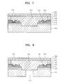
- a layer 400 is formed with a thickness in the range of 10 to 15 ⁇ m on the substrate 100 on which at least one adhesive portion 230 is formed. Then, a photo mask 320, in which a blocking portion 330 to form the chamber layer 430 is patterned, is used to cover the layer 400, and ultraviolet rays are irradiated thereon.
- the ultraviolet rays pass through the photo mask 300, except the blocking portion 330.
- the layer 400 is divided into portions 410 on which the ultraviolet rays did not pass through the blocking portion 330 and a portion 420 on which ultraviolet rays passed through the photo mask 300.
- the portion 420 is etchedand the portion 410 is not etched and becomes the chamber layer 430.
- the adhesive portion 230 is completely covered by the chamber layer 430, and thus not externally exposed from the chamber layer 430. Accordingly, since the adhesive portion 230 does not contact with ink, the adhesive portion 230 cannot be corroded.
- FIG. 10 is a view illustrating a method of examining adhesion of the adhesive portion 230, according to an embodiment of the present invention.
- an adhesive test piece 20 having a width, a height, and a thickness of 100 ⁇ m, 40 ⁇ m, and 15 ⁇ m, respectively, is attached to a substrate 10.
- a pressing tool 30, for applying force to the adhesive test piece 20, is disposed beside the adhesive test piece 20 to apply force to the adhesive test piece 20.
- the substrate 10 may be the same as the substrate 100.
- the pressing tool 30 is pushed in an arrow direction.
- Table 1 shows the result.
- Table 1 frequency adhesion(Kgf) 1 41.2 2 40.3 3 40.1 4 40.3 5 40.6 6 40.1 7 41.3 8 40.1 9 38.5 10 40.4 average 40.29
- the adhesion of the adhesive test piece 20 is over 40 Kgf.
- the adhesive test piece 20 of FIG. 10 may correspond to the adhesive portion 230 of FIG. 3 and/or the chamber layer 430 with the adhesive portion 230 of FIG. 4 .
- the trench 160 is formed by removing a portion of the passivation layer 140, the oxide film 110, and the substrate 100.
- the trench 160 is used as a portion of an ink path to supply ink into the chamber 430.
- the nozzle plate 600 including at least one nozzle 610 as a path for ejecting ink is formed on the sacrificial layer 500.
- the sacrificial layer 500 is formed on the substrate 100 so that a top and bottom of the substrate 100 and the sacrificial layer 500, respectively, contact each other.
- the manifold 170 is formed in the substrate 100 so that the manifold 170 contacts the bottom of the sacrificial layer 500.
- the sacrificial layer 500 is removed, and the removed part becomes the ink chamber 440 for temporarily storing ink that is to be ejected. Accordingly, the ink is introduced into the ink chamber 440 through the manifold 170 that is formed in the substrate 100 and the trench 160.
Abstract
Description
- The present invention relates to an inkjet printhead, and more particularly, to a bubble jet type inkjet printhead and a method of manufacturing the same.
- In general, ink ejection methods of an inkjet printer can be classified into an electro-thermal transducer type, which is also called a bubble jet type, and an electro-mechanical transducer type. In the electro-thermal transducer type, a heat source is used to generate bubbles in ink and the ink is ejected using the force of the generated bubbles. In the electro-mechanical transducer type, ink is ejected using a piezoelectric material, such that the ink is ejected according to the change in volume of the ink due to the deformation of the piezoelectric material.
- In the electro-thermal transducer type, the heat is transferred to the ink that is in contact with a heater and thus the temperature of the water-soluble ink is increased above the boiling point of the ink. Thus, when the temperature of the ink is increased above the boiling point, bubbles are formed, and these bubbles pressurize the ink around the bubbles. The pressurized ink is ejected through nozzles due to the difference between the atmospheric pressure and the pressure of the ink. While being ejected onto the paper, the ink forms ink droplets in order to minimize its surface energy. A drop-on-demand type is a type in which the above process is performed using a computer whenever necessary.
- The electro-thermal transducer type has a problem in terms of durability due to serial shocks generated by pressure of ink droplets generated by thermal energy. Also, it is difficult to control the size of the ink droplets and to increase the speed of ejecting the ink droplets.
- Recently, an array head type or a line head type including an inkjet printhead corresponding to the width of a sheet of paper is under development as the needs for higher operation speed and high integration increase.
- In the electro-mechanical transducer type, a piezoelectric material is attached to a diaphragm to pressurize a chamber of a printhead. Then, pressure is applied to the chamber to eject ink using the piezoelectric characteristic of generating a force when a voltage is applied. Thus, force is generated according to the applied voltage so as to apply pressure to the chamber, and thereby having an excellent characteristic in terms of speed.
- The electro-thermal transducer type inkjet printhead includes a substrate, a chamber, and a nozzle plate. The substrate includes a heater generating heat and a manifold supplying ink. The chamber surrounds the heater and forms an ink chamber for temporarily storing ink that is to be ejected. The nozzle plate is disposed over the chamber and includes a nozzle from which the ink is ejected, and the chamber is attached to the substrate using an adhesive layer that is formed of a resin-based material. When the adhesive layer is formed of a photo-insensitive material, the adhesive layer is formed by patterning using a dry etching method or a wet etching method. When the adhesive layer partially contacts with ink stored in the ink chamber, the adhesive layer should not react with the ink even when the adhesive layer contacts with the ink for long hours. Accordingly, the adhesive layer must have a high chemical resistance.
- The photo-insensitive adhesive layer is ideally patterned using photoresist via a photolithography process. Accordingly, the adhesive layer is formed on the substrate, and photoresist is applied on the adhesive layer. Then, a photo mask having a desired pattern is formed on the photoresist and ultraviolet rays are irradiated thereon to pattern the photoresist in a desired form. Then, the photoresist is developed with an etching solution, and the adhesive layer is patterned in a desired pattern by using an etching method. Accordingly, when the photo-insensitive adhesive layer is used, a process using photoresist is further necessary.
- Also, when a part of the adhesive layer contacts with ink stored in the ink chamber, an adhesive layer having chemical characteristics, in that the adhesive layer does not react with the ink, should be used. Accordingly, the material for forming the adhesive layer is limited.
- The present invention provides an inkjet printhead and a method of manufacturing the same to reduce the number of manufacturing processes by using a photo-sensitive material and include an adhesive layer formed so as not to contact with ink.
- Additional aspects and utilities of the present invention will be set forth in part in the description which follows and, in part, will be obvious from the description, or may be learned by practice of the invention.
- The foregoing and/or other aspects and utilities of the present invention may be achieved by providing an inkjet printhead, including a substrate, a chamber to define an ink chamber in an upper portion of the substrate, and an adhesive portion to attach the substrate and the chamber, wherein the adhesive portion is formed of a phenolic photo-sensitive resin.
- The foregoing and/or other aspects and utilities of the present invention may also be achieved by providing a method of manufacturing an inkjet printhead, the method including forming at least one heat source and an electrode on a substrate, forming an adhesive portion formed of a phenolic photo-sensitive resin on the substrate, forming a chamber on the adhesive portion to define an ink chamber that temporarily stores ink to be ejected so that the adhesive portion does not contact with the ink; and forming a nozzle plate on the chamber such that at least one nozzle is formed in the nozzle plate.
- The foregoing and/or other aspects and utilities of the present invention may be achieved by providing an inkjet printhead, including a substrate, a chamber layer to define an ink chamber on an upper portion of the substrate, and an adhesive portion to attach the substrate and the chamber layer, wherein at least a portion of the chamber layer is disposed between the ink chamber and the adhesive portion.
- The chamber layer may include the at least a portion and a middle portion receded from the at least a portion, and the adhesive portion may be disposed between the middle portion and the substrate.
- The adhesive portion may be spaced apart from the ink chamber by a distance to correspond to a thickness of the at least a portion of the chamber layer.
- The chamber layer may include a surface to define the ink chamber, and the surface is formed on the at least a portion of the chamber layer.
- The substrate may include one or more layers as a heat source and an electrode formed thereon to heat ink stored in the ink chamber, and the adhesive portion may be spaced-apart from the ink by a thickness of the at least a portion of the chamber layer.
- The adhesive portion may have a width narrower than a thickness of the chamber layer.
- The adhesive portion may not be exposed to the ink chamber.
- The above and other features and advantages of the present invention will become more apparent by describing in detail exemplary embodiments thereof with reference to the attached drawings in which:
-
FIGS. 1 through 9 are cross-sectional views illustrating a method of manufacturing an inkjet printhead, according to an embodiment of the present invention; and -
FIG. 10 is a perspective view illustrating a method of examining adhesion of an adhesive portion of an inkjet printhead, according to an embodiment of the present invention. - Reference will now be made in detail to the embodiments of the present invention, examples of which are illustrated in the accompanying drawings, wherein like reference numerals refer to the like elements throughout. The embodiments are described below in order to explain the present invention by referring to the figures.
-
FIGS. 1 through 9 are cross-sectional views of a method of manufacturing an inkjet printhead, according to an embodiment of the present invention. - A structure of the inkjet printhead formed according to the present embodiment of the present invention will now be described with reference to the accompanying drawings.
- Referring to
FIG. 9 , amanifold 170 and atrench 160 are formed in asubstrate 100 so as to supplyink 700 to anink chamber 440. Anoxide film 110 is formed on thesubstrate 100. Aheat source 120 is formed on theoxide film 110 to form bubbles by applying heat to theink 700. Anelectrode 130 is formed on theheat source 120 to supply current to theheat source 120. Theelectrode 130 is isolated from theink 700 by a protective layer in order to prevent theink 700 stored in theink chamber 440 from contacting with theelectrode 130 and thus corroding theelectrode 130. The inkjet printhead further includes apassivation layer 140 and ananti-cavitation layer 150. - A chamber layer, or wall, 430 is formed in an upper portion of the
substrate 100 to define theink chamber 440, and is attached to an upper side of thesubstrate 100, more particularly, to thepassivation layer 140 by anadhesive portion 230. Theadhesive portion 230 is completely covered by thechamber 430, and thus not externally exposed. Accordingly, theadhesive portion 230 does not contact theink 700 stored in theink chamber 440. Thus, occurrences of a chemical reaction between theadhesive portion 230 and theink 700 stored in theink chamber 440 can be prevented. Here, the above-described layers, for example, thepassivation layer 140, theelectrode 130, theheat source 120, and/oroxide film 110, disposed between thechamber layer 430 and thesubstrate 100 may be referred to as thesubstrate 100. - The
chamber layer 430 may include amiddle portion 430a andexterior portions middle portion 430a. Theadhesive portion 230 is formed between themiddle portion 430a and thepassivation layer 140. When themiddle portion 430a has a groove shape, theadhesive portion 230 may be disposed in themiddle portion 430a. Since theexterior portions passivation layer 140, theadhesive portion 230 is spaced-apart from a surface of thechamber layer 430 defining the ink chamber by a distance such that theexterior potions 430b and/or 430c keep the ink stored in theink chamber 430 from contacting theadhesive portion 230. - It is possible that the
chamber layer 430 may have themiddle portion 430a and theexterior portion 430b. - It is also possible that the
exterior portion 430b of thechamber layer 430 may be disposed between theadhesive portion 230 and a portion of theanti-cavitation layer 150. - A
nozzle plate 600 that includes a plurality ofnozzles ink chamber 440. Thenozzles nozzle plate 600 to respectively correspond to theanti-cavitation layer 150 or theheat source 120. - The method of manufacturing the inkjet printhead according to the present embodiment of the present invention will now be sequentially described with reference to the accompanying drawings.
- Referring to
FIG. 1 , anoxide film 110, formed of Si02 with a predetermined thickness, is formed on thesubstrate 100 formed of Si. One ormore heat sources 120, formed of TaN, are disposed on theoxide film 110 at a predetermined interval so as to apply heat to ink. At least oneelectrode 130, formed of Al, is disposed on theheat source 120 so as to supply power from a power source to thecorresponding heat source 120. Apassivation layer 140, formed of SiN with a predetermined thickness, is formed on theoxide film 110, theheat source 120, and theelectrode 130. Ananti-cavitation layer 150, formed of Ta with a predetermined thickness, is formed on a part of thepassivation layer 140 that is in contact with theheat source 120. - The
heat source 120, theelectrode 130, thepassivation layer 140, and theanti-cavitation layer 150 are formed using a photolithography process that is a widely known method to one of ordinary skill in the art, and thus the description thereof will be omitted. - Referring to
FIG. 2 , anadhesive layer 200 is formed with a thickness in the range of 2 to 3µm so as to cover thepassivation layer 140 and theanti-cavitation layer 150. Then, aphoto mask 300, in which a blockingportion 310 is patterned to form the adhesive portion 230 (seeFIG. 3 ), is used to cover theadhesive layer 200, and then ultraviolet rays are irradiated thereon. - The ultraviolet rays pass through the
photo mask 300, except the blockingportion 310. At this point, theadhesive layer 200 is divided intoportions 210, on which the ultraviolet rays did not pass through thephoto mask 300 due to the blockingportion 310, and aportion 220, on which ultraviolet rays passed through thephoto mask 300. - When the
substrate 100 is disposed in a predetermined solution, such as a photoresist developer, theportion 220 is etched because theportion 220 has been exposed to ultraviolet rays, however, theportions 210 are not etched and each become the adhesive portion 230 (seeFIG. 3 ). - The
adhesive layer 200 may be formed of a photosensitive material, for example, a phenolic material, and may use, for example, WPR-1201 made by JSR Co., Ltd.
WPR-1201 is a phenolic photosensitive resin and can be used in a photolithography process. Accordingly, since the WPR-1201 does not need to use a process using photoresist, unlike other materials, the manufacturing process can be simple. - Referring to
FIGS. 3 and 4 , alayer 400 is formed with a thickness in the range of 10 to 15µm on thesubstrate 100 on which at least oneadhesive portion 230 is formed. Then, aphoto mask 320, in which a blockingportion 330 to form thechamber layer 430 is patterned, is used to cover thelayer 400, and ultraviolet rays are irradiated thereon. - The ultraviolet rays pass through the
photo mask 300, except the blockingportion 330. At this point, thelayer 400 is divided intoportions 410 on which the ultraviolet rays did not pass through the blockingportion 330 and aportion 420 on which ultraviolet rays passed through thephoto mask 300. - When the
substrate 100 is disposed in a predetermined developer solution, theportion 420 is etchedand theportion 410 is not etched and becomes thechamber layer 430. - At this point, the
adhesive portion 230 is completely covered by thechamber layer 430, and thus not externally exposed from thechamber layer 430. Accordingly, since theadhesive portion 230 does not contact with ink, theadhesive portion 230 cannot be corroded. - An experiment for examining adhesion of the
adhesive portion 230 was performed using anadhesive test piece 20 as theadhesive portion 230. -
FIG. 10 is a view illustrating a method of examining adhesion of theadhesive portion 230, according to an embodiment of the present invention. - Referring to
FIG. 10 , anadhesive test piece 20 having a width, a height, and a thickness of 100µm, 40µm, and 15µm, respectively, is attached to asubstrate 10. Apressing tool 30, for applying force to theadhesive test piece 20, is disposed beside theadhesive test piece 20 to apply force to theadhesive test piece 20. Thesubstrate 10 may be the same as thesubstrate 100. - The
pressing tool 30 is pushed in an arrow direction. When theadhesive test piece 20 is separated from thesubstrate 10 by applying force to theadhesive test piece 20, the force applied to thepressing tool 30 is measured. Table 1 shows the result.Table 1 frequency adhesion(Kgf) 1 41.2 2 40.3 3 40.1 4 40.3 5 40.6 6 40.1 7 41.3 8 40.1 9 38.5 10 40.4 average 40.29 - According to the above Table 1, the adhesion of the
adhesive test piece 20 is over 40 Kgf. - The
adhesive test piece 20 ofFIG. 10 may correspond to theadhesive portion 230 ofFIG. 3 and/or thechamber layer 430 with theadhesive portion 230 ofFIG. 4 . - Referring to
FIG. 5 , thetrench 160 is formed by removing a portion of thepassivation layer 140, theoxide film 110, and thesubstrate 100. Thetrench 160 is used as a portion of an ink path to supply ink into thechamber 430. - Referring to
FIG. 6 , asacrificial layer 500 formed of, for example, the photoresist ODUR, is formed on thesubstrate 100 so that thesacrificial layer 500 is flush with the surface of thechamber 430. - Referring to
FIG. 7 , thenozzle plate 600 including at least onenozzle 610 as a path for ejecting ink is formed on thesacrificial layer 500. - Referring to
FIG. 8 , thesacrificial layer 500 is formed on thesubstrate 100 so that a top and bottom of thesubstrate 100 and thesacrificial layer 500, respectively, contact each other. The manifold 170 is formed in thesubstrate 100 so that the manifold 170 contacts the bottom of thesacrificial layer 500. - Referring to
FIG. 9 , thesacrificial layer 500 is removed, and the removed part becomes theink chamber 440 for temporarily storing ink that is to be ejected. Accordingly, the ink is introduced into theink chamber 440 through the manifold 170 that is formed in thesubstrate 100 and thetrench 160. - While the present invention has been particularly shown and described with reference to exemplary embodiments thereof, it will be understood by one of ordinary skill in the art that various changes in form and details may be made therein without departing from the scope of the present invention as defined by the following claims.
Claims (14)
- An inkjet printhead, comprising:a substrate (100);a chamber wall (430) defining an ink chamber (440) in an upper portion of the substrate; andan adhesive portion (230) for attaching the substrate to the chamber wall, wherein the adhesive portion comprises a photosensitive resin.
- The inkjet printhead of claim 1, photosensitive resin comprises a phenolic resin.
- The inkjet printhead of claim 1 or 2, wherein the adhesion of the adhesive portion is over 40 Kgf.
- The inkjet printhead of any one of the preceding claims, wherein the adhesive portion does not contact with ink stored in the ink chamber.
- A method of manufacturing an inkjet printhead, the method comprising:forming at least one heat source (120) and an electrode (130) on a substrate;forming an adhesive portion (230), formed of a photosensitive resin, on the substrate;forming a chamber wall (430) on the adhesive portion to define an ink chamber for temporarily storing ink to be ejected, so that the adhesive portion does not contact with the ink; andforming a nozzle plate (600) on the chamber wall (430) with at least one nozzle formed in the nozzle plate.
- The method of claim 5, comprising forming the adhesive portion using a photoresist process.
- The method of claim 6, wherein the adhesion of the adhesive portion is over 40 Kgf.
- An inkjet printhead, comprising:a substrate (100);a chamber wall (430) defining an ink chamber (440) on an upper portion of the substrate; andan adhesive portion (230) for attaching the substrate to the chamber wall,wherein a portion (430b) of the chamber wall (430) is disposed between the ink chamber and the adhesive portion.
- The inkjet printhead of claim 8, wherein the chamber wall comprises a recess (430a), wherein the adhesive portion is disposed in the recess.
- The inkjet printhead of claim 8 or 9, wherein the adhesive portion is spaced apart from the ink chamber by a distance corresponding to a thickness of the portion of the chamber layer.
- The inkjet printhead of claim 8, 9 or 10, wherein the chamber wall comprises a surface to define the ink chamber, and the surface is formed on the portion of the chamber wall.
- The inkjet printhead of any one of claims 8 to 11, wherein the substrate comprises one or more layers as a heat source and an electrode formed thereon to heat ink stored in the ink chamber.
- The inkjet printhead of any one of claims 8 to 12, wherein the adhesive portion has a width narrower than a thickness of the chamber wall.
- The inkjet printhead of any one of claims 8 to 13, wherein the adhesive portion is not exposed to the ink chamber.
Applications Claiming Priority (1)
| Application Number | Priority Date | Filing Date | Title |
|---|---|---|---|
| KR1020070129082A KR20090062012A (en) | 2007-12-12 | 2007-12-12 | Inkjet head and method for manufacturing the same |
Publications (1)
| Publication Number | Publication Date |
|---|---|
| EP2070703A1 true EP2070703A1 (en) | 2009-06-17 |
Family
ID=40428225
Family Applications (1)
| Application Number | Title | Priority Date | Filing Date |
|---|---|---|---|
| EP08159826A Withdrawn EP2070703A1 (en) | 2007-12-12 | 2008-07-07 | Inkjet Printhead and Method of Manufacturing the Same |
Country Status (5)
| Country | Link |
|---|---|
| US (1) | US20090153623A1 (en) |
| EP (1) | EP2070703A1 (en) |
| JP (1) | JP2009143228A (en) |
| KR (1) | KR20090062012A (en) |
| CN (1) | CN101456283A (en) |
Families Citing this family (6)
| Publication number | Priority date | Publication date | Assignee | Title |
|---|---|---|---|---|
| US9050807B2 (en) * | 2013-05-14 | 2015-06-09 | Xerox Corporation | Process for bonding interstitial epoxy adhesive for fabrication of printhead structures in high density printheads |
| CN104417065B (en) * | 2013-09-10 | 2016-03-02 | 珠海赛纳打印科技股份有限公司 | Ink gun manufacture method, ink gun and printing device |
| CN107073960B (en) * | 2014-10-30 | 2019-11-08 | 惠普发展公司,有限责任合伙企业 | Inkjet print head |
| JP6431605B2 (en) * | 2014-10-30 | 2018-11-28 | ヒューレット−パッカード デベロップメント カンパニー エル.ピー.Hewlett‐Packard Development Company, L.P. | Inkjet print head |
| JP6493665B2 (en) * | 2015-03-13 | 2019-04-03 | セイコーエプソン株式会社 | MEMS device, liquid ejecting head, and liquid ejecting apparatus |
| CN107206793B (en) * | 2015-04-10 | 2018-12-04 | 惠普发展公司,有限责任合伙企业 | The tilting section of metallic conductor is removed when forming print head |
Citations (9)
| Publication number | Priority date | Publication date | Assignee | Title |
|---|---|---|---|---|
| US5484823A (en) * | 1989-12-14 | 1996-01-16 | Canon Kabushiki Kaisha | Photopolymerizable adhesive for preventing peeling and separation at a joint section between first and second members of an ink jet printing head and a method of using the same |
| EP0890438A2 (en) * | 1997-07-03 | 1999-01-13 | Lexmark International, Inc. | Printhead having heating element conductors arranged in spaced appart planes |
| EP1078758A2 (en) * | 1999-08-24 | 2001-02-28 | Canon Kabushiki Kaisha | Substrate unit for liquid discharging head, method for producting the same, liquid discharging head, cartridge, and image forming apparatus |
| US6387719B1 (en) * | 2001-02-28 | 2002-05-14 | Lexmark International, Inc. | Method for improving adhesion |
| EP1234671A1 (en) * | 2001-02-23 | 2002-08-28 | Canon Kabushiki Kaisha | Ink jet head, producing method therefor and ink jet recording apparatus |
| US6450622B1 (en) * | 2001-06-28 | 2002-09-17 | Hewlett-Packard Company | Fluid ejection device |
| WO2004092237A2 (en) * | 2003-04-14 | 2004-10-28 | Lexmark International, Inc. | Radiation curable resin layer |
| US20050093924A1 (en) * | 2003-06-16 | 2005-05-05 | Canon Kabushiki Kaisha | Photosensitive resin composition, ink-jet recording head using the composition, and production method for the same |
| US20060061626A1 (en) * | 2002-12-27 | 2006-03-23 | Canon Kabushiki Kaisha | Substrate for ink jet head, ink jet head utilizing the same and producing method therefor |
-
2007
- 2007-12-12 KR KR1020070129082A patent/KR20090062012A/en not_active Application Discontinuation
-
2008
- 2008-07-07 EP EP08159826A patent/EP2070703A1/en not_active Withdrawn
- 2008-07-22 CN CNA2008101343126A patent/CN101456283A/en active Pending
- 2008-08-20 US US12/194,764 patent/US20090153623A1/en not_active Abandoned
- 2008-12-09 JP JP2008313514A patent/JP2009143228A/en active Pending
Patent Citations (9)
| Publication number | Priority date | Publication date | Assignee | Title |
|---|---|---|---|---|
| US5484823A (en) * | 1989-12-14 | 1996-01-16 | Canon Kabushiki Kaisha | Photopolymerizable adhesive for preventing peeling and separation at a joint section between first and second members of an ink jet printing head and a method of using the same |
| EP0890438A2 (en) * | 1997-07-03 | 1999-01-13 | Lexmark International, Inc. | Printhead having heating element conductors arranged in spaced appart planes |
| EP1078758A2 (en) * | 1999-08-24 | 2001-02-28 | Canon Kabushiki Kaisha | Substrate unit for liquid discharging head, method for producting the same, liquid discharging head, cartridge, and image forming apparatus |
| EP1234671A1 (en) * | 2001-02-23 | 2002-08-28 | Canon Kabushiki Kaisha | Ink jet head, producing method therefor and ink jet recording apparatus |
| US6387719B1 (en) * | 2001-02-28 | 2002-05-14 | Lexmark International, Inc. | Method for improving adhesion |
| US6450622B1 (en) * | 2001-06-28 | 2002-09-17 | Hewlett-Packard Company | Fluid ejection device |
| US20060061626A1 (en) * | 2002-12-27 | 2006-03-23 | Canon Kabushiki Kaisha | Substrate for ink jet head, ink jet head utilizing the same and producing method therefor |
| WO2004092237A2 (en) * | 2003-04-14 | 2004-10-28 | Lexmark International, Inc. | Radiation curable resin layer |
| US20050093924A1 (en) * | 2003-06-16 | 2005-05-05 | Canon Kabushiki Kaisha | Photosensitive resin composition, ink-jet recording head using the composition, and production method for the same |
Also Published As
| Publication number | Publication date |
|---|---|
| CN101456283A (en) | 2009-06-17 |
| US20090153623A1 (en) | 2009-06-18 |
| KR20090062012A (en) | 2009-06-17 |
| JP2009143228A (en) | 2009-07-02 |
Similar Documents
| Publication | Publication Date | Title |
|---|---|---|
| US6762012B2 (en) | Method of manufacturing monolithic ink-jet printhead | |
| EP2070703A1 (en) | Inkjet Printhead and Method of Manufacturing the Same | |
| KR100474423B1 (en) | bubble-ink jet print head and fabrication method therefor | |
| EP1908593A1 (en) | Inkjet printhead and method of manufaturing the same | |
| US20060134555A1 (en) | Monolithic inkjet printhead and method of manufacturing the same | |
| US20080180486A1 (en) | Liquid ejection head and method for manufacturing liquid ejection head | |
| US6926386B2 (en) | Inkjet printer head and method of fabricating the same | |
| JP2006027273A (en) | Method of manufacturing inkjet head | |
| EP2000308B1 (en) | Ink jet print head and manufacturing method thereof | |
| US20080128386A1 (en) | Method of manufacturing inkjet printhead | |
| US20080049073A1 (en) | Inkjet printhead and method of manufacturing the same | |
| EP0894628B1 (en) | Liquid discharging method, liquid discharging head, and head cartridge and liquid discharging apparatus using said liquid discharging head | |
| EP1946929A2 (en) | Ink-jet Print Head and Method for Manufacturing the Same | |
| KR100882041B1 (en) | Liquid discharge head and manufacturing method of the same | |
| KR100828360B1 (en) | Inkjet printhead and method of manufacturing the same | |
| US8137573B2 (en) | Liquid ejection head, method for manufacturing liquid ejection head, and method for manufacturing structure | |
| KR20080086306A (en) | Method for manufacturing ink-jet print head | |
| US20130152390A1 (en) | Process for producing a liquid ejection head | |
| US8114578B2 (en) | Method of manufacturing photosensitive epoxy structure using photolithography process and method of manufacturing inkjet printhead using the method of manufacturing photosensitive epoxy structure | |
| KR101117285B1 (en) | Fabrication Method For Ink-jet Printhead | |
| KR20040049064A (en) | Method for manufacturing monolithic inkjet printhead | |
| US20060284938A1 (en) | Inkjet printhead and method of manufacturing the same | |
| KR20070055174A (en) | Fabrication method for ink-jet print head | |
| KR20040005155A (en) | A forming method for a ink supply pass of a ink jet head |
Legal Events
| Date | Code | Title | Description |
|---|---|---|---|
| PUAI | Public reference made under article 153(3) epc to a published international application that has entered the european phase |
Free format text: ORIGINAL CODE: 0009012 |
|
| AK | Designated contracting states |
Kind code of ref document: A1 Designated state(s): AT BE BG CH CY CZ DE DK EE ES FI FR GB GR HR HU IE IS IT LI LT LU LV MC MT NL NO PL PT RO SE SI SK TR |
|
| AX | Request for extension of the european patent |
Extension state: AL BA MK RS |
|
| 17P | Request for examination filed |
Effective date: 20091120 |
|
| 17Q | First examination report despatched |
Effective date: 20100107 |
|
| AKX | Designation fees paid |
Designated state(s): DE FR GB NL |
|
| STAA | Information on the status of an ep patent application or granted ep patent |
Free format text: STATUS: THE APPLICATION IS DEEMED TO BE WITHDRAWN |
|
| 18D | Application deemed to be withdrawn |
Effective date: 20111130 |