EP2070610A1 - Systems and methods involving wax patterns - Google Patents
Systems and methods involving wax patterns Download PDFInfo
- Publication number
- EP2070610A1 EP2070610A1 EP08253875A EP08253875A EP2070610A1 EP 2070610 A1 EP2070610 A1 EP 2070610A1 EP 08253875 A EP08253875 A EP 08253875A EP 08253875 A EP08253875 A EP 08253875A EP 2070610 A1 EP2070610 A1 EP 2070610A1
- Authority
- EP
- European Patent Office
- Prior art keywords
- mold
- pattern
- fixture
- positioning
- mold assembly
- Prior art date
- Legal status (The legal status is an assumption and is not a legal conclusion. Google has not performed a legal analysis and makes no representation as to the accuracy of the status listed.)
- Granted
Links
- 238000000034 method Methods 0.000 title claims abstract description 16
- 238000011960 computer-aided design Methods 0.000 claims description 26
- 239000000470 constituent Substances 0.000 claims 1
- 238000010586 diagram Methods 0.000 description 8
- 239000000463 material Substances 0.000 description 8
- 230000006870 function Effects 0.000 description 3
- 230000003287 optical effect Effects 0.000 description 3
- 238000005266 casting Methods 0.000 description 2
- 230000007246 mechanism Effects 0.000 description 2
- 238000012986 modification Methods 0.000 description 2
- 230000004048 modification Effects 0.000 description 2
- 239000004065 semiconductor Substances 0.000 description 2
- 230000015572 biosynthetic process Effects 0.000 description 1
- 239000000872 buffer Substances 0.000 description 1
- 238000010276 construction Methods 0.000 description 1
- 238000004519 manufacturing process Methods 0.000 description 1
- 238000000465 moulding Methods 0.000 description 1
- 238000012545 processing Methods 0.000 description 1
- 238000005476 soldering Methods 0.000 description 1
- 238000003860 storage Methods 0.000 description 1
- 230000032258 transport Effects 0.000 description 1
Images


Classifications
-
- B—PERFORMING OPERATIONS; TRANSPORTING
- B22—CASTING; POWDER METALLURGY
- B22C—FOUNDRY MOULDING
- B22C7/00—Patterns; Manufacture thereof so far as not provided for in other classes
- B22C7/02—Lost patterns
Definitions
- the disclosure generally relates to casting.
- Manufacture of components can be accomplished using various techniques. Oftentimes, casting processes are used that involve formation of a component shape using a sacrificial material. This sacrificial material can be covered by another material in order to form a pattern mold of desired component shape. This involves removing the sacrificial material from the pattern mold so that material used to form the actual component can be placed in the location vacated by the sacrificial material for molding.
- an exemplary embodiment of a system comprises: a mold assembly unit having a movable fixture holder operative to engage a portion of a pattern mold and position the pattern mold for assembly.
- An exemplary embodiment of a method comprises: interpreting a computer aided design (CAD) model of a mold assembly; providing a pattern mold having a component mold and a fixture; and positioning the fixture based, at least in part, upon information corresponding to the CAD model such that positioning of the fixture accommodates positioning of the pattern mold.
- CAD computer aided design
- Another exemplary embodiment of a method comprises: providing a pattern mold having a component mold and a fixture; providing a movable fixture holder operative to engage the fixture of the pattern mold and position the pattern mold for assembly; and automatically positioning the fixture using the fixture holder based, at least in part, upon information corresponding to a computer aided design (CAD) model of a mold assembly.
- CAD computer aided design
- CAD Computer Aided Design
- a mold assembly unit that constructs a mold assembly.
- the mold assembly unit correlates position information from the model with patterns used to form the mold assembly, thereby reducing the potential for technician-injected placement errors that tend to occur during manual construction of such an assembly. Therefore, by using a mold assembly unit, calibrated repeatable assembly steps can be accommodated.
- FIG. 1 is a schematic diagram depicting an exemplary embodiment of a system involving pattern molds.
- system 100 incorporates a CAD system 102 that is used to provide information corresponding to a CAD model 103 to a mold assembly system 104.
- the mold assembly system 104 interprets the CAD model 103 and provides instructions corresponding to positions of various features of the CAD model 103 to a mold assembly unit 106. Responsive to the instructions, the mold assembly unit 106 positions various patterns, e.g., pattern 108, to form a mold assembly, e.g., mold assembly 110. Once positioned, a technician can join the patterns 108 to the mold assembly 110, such as by wax soldering when the pattern 108 is formed of wax.
- patterns e.g., pattern 108 e.g., pattern 108
- functionality of an embodiment of a mold assembly system involves interpreting a CAD model such as depicted in block 112.
- the mold assembly system interprets the model to determine pattern positioning.
- the mold assembly system provides instructions for positioning patterns 108 based, at least in part, on the interpretation of the CAD model 103.
- the instructions can be provided to a mold assembly unit 106.
- FIG. 3 Functionality of an embodiment of a mold assembly unit (e.g., mold assembly unit 106 of FIG. 1 ) is depicted in the flowchart of FIG. 3 .
- the mold assembly unit receives instructions corresponding to the positioning of one or more mold patterns, as depicted in block 116. Then, as depicted in block 118, the patterns are positioned using the instructions.
- mold assembly unit 200 includes a workbench 202, a turntable 204 and a controlled end-of-arm fixture holder 206.
- a base 208 of the turntable 204 is fixed in position relative to a horizontal rail 210.
- a vertical rail 212 is slidably attached to the horizontal rail such that the vertical rail can translate horizontally along the horizontal rail.
- the end-of-arm fixture holder 206 is attached to a horizontal arm 214 that extends outwardly from the vertical rail 212.
- relative positioning of the end-of-arm fixture holder 206 and the turntable 204 can be adjusted by rotating the turntable 204, vertically positioning the horizontal arm 214 with respect to the vertical rail 212 and/or horizontally positioning the vertical rail 212 with respect to the horizontal rail 210.
- the aforementioned positioning is accomplished by one or more stepper motors.
- the end-of-arm fixture holder 206 accommodates clamping of patterns (e.g., pattern 108 of FIG. 1 ) so that the patterns can be positioned for assembly.
- the end-of-arm fixture holder 206 incorporates two compound-angle vice blocks 242, 244, which move relative to a base 246.
- the vice blocks 242, 244 are adjustable between open and closed positions via a thumbscrew 248 that is mounted to the base 246.
- a vertical adjustment (fine-tuning) mechanism 250 is mounted between the end-of-arm fixture holder 206 and the horizontal arm 214.
- vertical adjustment mechanism 250 incorporates a base 252, which attaches to the horizontal arm 214, and an adjustable faceplate 254, which attaches to a back of the fixture holder 206.
- a thumbscrew 256 which is mounted to the base 252, accommodates vertical positioning of the fixture holder 206.
- mold assembly unit 300 incorporates a turntable 302, with a base 303 of the turntable 302 being fixed in position relative to a horizontal rail assembly 304.
- the horizontal rail assembly 304 includes rails 306, 308 that are spaced from each other to provide a track along which a vertical rail 310 can translate.
- An end-of-arm fixture holder 312 (which, in this embodiment, is identical to fixture holder 206 of FIG. 4 ) is positioned by a horizontal arm 314. Horizontal arm 314 moves vertically along the vertical rail 310.
- mold assembly unit 300 is manually controlled.
- correlation between a CAD model and positioning of a pattern by mold assembly unit 300 is accommodated by a series of position indicators (not shown) located along each of the horizontal rail assembly 304, the vertical rail 310 and the fixture holder 312.
- mold pattern 350 incorporates a component mold 352, which is configured in this embodiment as a gas turbine engine blade. Feeding passages 354 are provided for enabling material to flow into the mold 352, and gating passages 356 are provided for enabling material to flow through the mold 352. Additionally, the pattern 350 incorporates an end-of-arm fixture 360.
- the end-of-arm fixture 360 is configured to enable positioning of the pattern 350. Specifically, the fixture 360 is designed such that, when the fixture 360 is seated within a corresponding fixture holder (e.g., fixture holder 206 of a mold assembly unit 200), proper orientation of the pattern 350 is established.
- mold pattern 350 is held in position relative to mold cage 370 by mold assembly unit 200.
- the end-of-arm fixture 360 is held by end-of-arm fixture holder 206.
- Various functionality can be implemented in hardware and/or software.
- a computing device can be used to implement various functionality, such as that depicted in FIGS. 2 and 3 .
- such a computing device can include a processor, memory, and one or more input and/or output (I/O) device interface(s) that are communicatively coupled via a local interface.
- the local interface can include, for example but not limited to, one or more buses and/or other wired or wireless connections.
- the local interface may have additional elements, which are omitted for simplicity, such as controllers, buffers (caches), drivers, repeaters, and receivers to enable communications. Further, the local interface may include address, control, and/or data connections to enable appropriate communications among the aforementioned components.
- the processor may be a hardware device for executing software, particularly software stored in memory.
- the processor can be a custom made or commercially available processor, a central processing unit (CPU), an auxiliary processor among several processors associated with the computing device, a semiconductor based microprocessor (in the form of a microchip or chip set) or generally any device for executing software instructions.
- the memory can include any one or combination of volatile memory elements (e.g., random access memory (RAM, such as DRAM, SRAM, SDRAM, VRAM, etc.)) and/or nonvolatile memory elements (e.g., ROM, hard drive, tape, CD-ROM, etc.).
- volatile memory elements e.g., random access memory (RAM, such as DRAM, SRAM, SDRAM, VRAM, etc.)
- nonvolatile memory elements e.g., ROM, hard drive, tape, CD-ROM, etc.
- the memory may incorporate electronic, magnetic, optical, and/or other types of storage media.
- the memory can also have a distributed architecture, where various components are situated remotely from one another, but can be accessed by the processor.
- the software in the memory may include one or more separate programs, each of which includes an ordered listing of executable instructions for implementing logical functions.
- a system component embodied as software may also be construed as a source program, executable program (object code), script, or any other entity comprising a set of instructions to be performed.
- the program is translated via a compiler, assembler, interpreter, or the like, which may or may not be included within the memory.
- the Input/Output devices that may be coupled to system I/O Interface(s) may include input devices, for example but not limited to, a keyboard, mouse, scanner, microphone, camera, proximity device, etc. Further, the Input/Output devices may also include output devices, for example but not limited to, a printer, display, etc. Finally, the Input/Output devices may further include devices that communicate both as inputs and outputs, for instance but not limited to, a modulator/demodulator (modem; for accessing another device, system, or network), a radio frequency (RF) or other transceiver, a telephonic interface, a bridge, a router, etc.
- modem for accessing another device, system, or network
- RF radio frequency
- the processor can be configured to execute software stored within the memory, to communicate data to and from the memory, and to generally control operations of the computing device pursuant to the software.
- Software in memory, in whole or in part, is read by the processor, perhaps buffered within the processor, and then executed.
- each block can be interpreted to represent a module, segment, or portion of code, which comprises one or more executable instructions for implementing the specified logical function(s).
- the functions noted in the blocks may occur out of the order and/or not at all. For example, two blocks shown in succession may in fact be executed substantially concurrently or the blocks may sometimes be executed in the reverse order, depending upon the functionality involved.
- any of the functionality described herein can be embodied in any computer-readable medium for use by or in connection with an instruction execution system, apparatus, or device, such as a computer-based system, processor-containing system, or other system that can fetch the instructions from the instruction execution system, apparatus, or device and execute the instructions.
- a "computer-readable medium” contains, stores, communicates, propagates and/or transports the program for use by or in connection with the instruction execution system, apparatus, or device.
- the computer readable medium can be, for example but not limited to, an electronic, magnetic, optical, electromagnetic, infrared, or semiconductor system, apparatus, or device.
- a computer-readable medium includes a portable computer diskette (magnetic), a random access memory (RAM) (electronic), a read-only memory (ROM) (electronic), an erasable programmable read-only memory (EPROM or Flash memory) (electronic), and a portable compact disc read-only memory (CDROM) (optical).
- RAM random access memory
- ROM read-only memory
- EPROM or Flash memory erasable programmable read-only memory
- CDROM compact disc read-only memory
Landscapes
- Engineering & Computer Science (AREA)
- Mechanical Engineering (AREA)
- Moulds For Moulding Plastics Or The Like (AREA)
Abstract
Description
- The disclosure generally relates to casting.
- Manufacture of components, such as gas turbine engine components, can be accomplished using various techniques. Oftentimes, casting processes are used that involve formation of a component shape using a sacrificial material. This sacrificial material can be covered by another material in order to form a pattern mold of desired component shape. This involves removing the sacrificial material from the pattern mold so that material used to form the actual component can be placed in the location vacated by the sacrificial material for molding.
- System and methods involving pattern molds are provided. In this regard, an exemplary embodiment of a system comprises: a mold assembly unit having a movable fixture holder operative to engage a portion of a pattern mold and position the pattern mold for assembly.
- An exemplary embodiment of a method comprises: interpreting a computer aided design (CAD) model of a mold assembly; providing a pattern mold having a component mold and a fixture; and positioning the fixture based, at least in part, upon information corresponding to the CAD model such that positioning of the fixture accommodates positioning of the pattern mold.
- Another exemplary embodiment of a method comprises: providing a pattern mold having a component mold and a fixture; providing a movable fixture holder operative to engage the fixture of the pattern mold and position the pattern mold for assembly; and automatically positioning the fixture using the fixture holder based, at least in part, upon information corresponding to a computer aided design (CAD) model of a mold assembly.
- Other systems, methods, features and/or advantages of this disclosure will be or may become apparent to one with skill in the art upon examination of the following drawings and detailed description. It is intended that all such additional systems, methods, features and/or advantages be included within this description and be within the scope of the present disclosure.
- Many aspects of the disclosure can be better understood with reference to the following drawings. The components in the drawings are not necessarily to scale. Moreover, in the drawings, like reference numerals designate corresponding parts throughout the several views.
-
FIG. 1 is a schematic diagram depicting an embodiment of a system involving pattern molds. -
FIG. 2 is a flowchart depicting functionality of an embodiment of a mold assembly system. -
FIG. 3 is a flowchart depicting functionality of an embodiment of a mold assembly unit. -
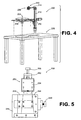
FIG. 4 is a partially exploded schematic diagram depicting an exemplary embodiment of a mold assembly unit. -
FIG. 5 is a partially exploded schematic diagram depicting an embodiment of an end-of-arm fixture holder. -
FIG. 6 is a schematic diagram depicting another exemplary embodiment of a mold assembly unit. -
FIG. 7 is a schematic diagram depicting an exemplary embodiment of a pattern. -
FIG. 8 is a schematic diagram depicting the assembly unit ofFIG. 4 positioning the pattern mold ofFIG. 7 to form a mold assembly. - System and methods involving pattern molds are provided, several exemplary embodiments of which will be described in detail. In this regard, some embodiments involve the use of wax pattern molds to form gas turbine engine components. In some embodiments, a Computer Aided Design (CAD) model of a mold assembly is interpreted and information corresponding to the model is provided to a mold assembly unit that constructs a mold assembly. Notably, the mold assembly unit correlates position information from the model with patterns used to form the mold assembly, thereby reducing the potential for technician-injected placement errors that tend to occur during manual construction of such an assembly. Therefore, by using a mold assembly unit, calibrated repeatable assembly steps can be accommodated.
- Referring now in more detail to the drawings,
FIG. 1 is a schematic diagram depicting an exemplary embodiment of a system involving pattern molds. As shown inFIG. 1 ,system 100 incorporates aCAD system 102 that is used to provide information corresponding to aCAD model 103 to amold assembly system 104. Themold assembly system 104 interprets theCAD model 103 and provides instructions corresponding to positions of various features of theCAD model 103 to amold assembly unit 106. Responsive to the instructions, themold assembly unit 106 positions various patterns, e.g.,pattern 108, to form a mold assembly, e.g.,mold assembly 110. Once positioned, a technician can join thepatterns 108 to themold assembly 110, such as by wax soldering when thepattern 108 is formed of wax. - As shown in
FIG. 2 , functionality of an embodiment of a mold assembly system (e.g.,mold assembly system 104 ofFIG. 1 ) involves interpreting a CAD model such as depicted inblock 112. In particular, the mold assembly system interprets the model to determine pattern positioning. Then, as depicted inblock 114, the mold assembly system provides instructions forpositioning patterns 108 based, at least in part, on the interpretation of theCAD model 103. By way of example, the instructions can be provided to amold assembly unit 106. - Functionality of an embodiment of a mold assembly unit (e.g.,
mold assembly unit 106 ofFIG. 1 ) is depicted in the flowchart ofFIG. 3 . As shown inFIG. 3 , the mold assembly unit receives instructions corresponding to the positioning of one or more mold patterns, as depicted inblock 116. Then, as depicted inblock 118, the patterns are positioned using the instructions. - An embodiment of a mold assembly unit is depicted in the partially exploded schematic diagram of
FIG. 4 . As shown inFIG. 4 ,mold assembly unit 200 includes aworkbench 202, aturntable 204 and a controlled end-of-arm fixture holder 206. In the embodiment ofFIG. 4 , abase 208 of theturntable 204 is fixed in position relative to ahorizontal rail 210. Avertical rail 212 is slidably attached to the horizontal rail such that the vertical rail can translate horizontally along the horizontal rail. The end-of-arm fixture holder 206 is attached to ahorizontal arm 214 that extends outwardly from thevertical rail 212. - In operation, relative positioning of the end-of-
arm fixture holder 206 and theturntable 204 can be adjusted by rotating theturntable 204, vertically positioning thehorizontal arm 214 with respect to thevertical rail 212 and/or horizontally positioning thevertical rail 212 with respect to thehorizontal rail 210. Notably, in this embodiment, the aforementioned positioning is accomplished by one or more stepper motors. - As shown in greater detail in
FIG. 5 , the end-of-arm fixture holder 206 accommodates clamping of patterns (e.g.,pattern 108 ofFIG. 1 ) so that the patterns can be positioned for assembly. In the embodiment ofFIG. 5 , the end-of-arm fixture holder 206 incorporates two compound-angle vice blocks base 246. Thevice blocks thumbscrew 248 that is mounted to thebase 246. - A vertical adjustment (fine-tuning)
mechanism 250 is mounted between the end-of-arm fixture holder 206 and thehorizontal arm 214. In this embodiment,vertical adjustment mechanism 250 incorporates abase 252, which attaches to thehorizontal arm 214, and anadjustable faceplate 254, which attaches to a back of thefixture holder 206. Athumbscrew 256, which is mounted to thebase 252, accommodates vertical positioning of thefixture holder 206. - Another embodiment of a mold assembly unit is depicted schematically in
FIG. 6 . As shown inFIG. 6 ,mold assembly unit 300 incorporates aturntable 302, with abase 303 of theturntable 302 being fixed in position relative to ahorizontal rail assembly 304. In this embodiment, thehorizontal rail assembly 304 includesrails vertical rail 310 can translate. An end-of-arm fixture holder 312 (which, in this embodiment, is identical tofixture holder 206 ofFIG. 4 ) is positioned by ahorizontal arm 314.Horizontal arm 314 moves vertically along thevertical rail 310. - In contrast to the embodiment of
FIG. 4 ,mold assembly unit 300 is manually controlled. In this regard, correlation between a CAD model and positioning of a pattern bymold assembly unit 300 is accommodated by a series of position indicators (not shown) located along each of thehorizontal rail assembly 304, thevertical rail 310 and thefixture holder 312. - An embodiment of a mold pattern that can be positioned by a mold assembly unit is depicted schematically in
FIG. 7 . As shown inFIG. 7 ,mold pattern 350 incorporates acomponent mold 352, which is configured in this embodiment as a gas turbine engine blade. Feedingpassages 354 are provided for enabling material to flow into themold 352, and gatingpassages 356 are provided for enabling material to flow through themold 352. Additionally, thepattern 350 incorporates an end-of-arm fixture 360. The end-of-arm fixture 360 is configured to enable positioning of thepattern 350. Specifically, thefixture 360 is designed such that, when thefixture 360 is seated within a corresponding fixture holder (e.g.,fixture holder 206 of a mold assembly unit 200), proper orientation of thepattern 350 is established. Thereafter, horizontal and vertical positioning of the end-of-arm fixture holder 360 by themold assembly unit 200 in combination with positioning of amold cage 370 using the turntable can properly position themold pattern 350 relative to themold cage 370. In this regard, positioning of amold pattern 350 relative to arepresentative mold cage 370 is depicted schematically inFIG. 8 . - As shown in
FIG. 8 ,mold pattern 350 is held in position relative tomold cage 370 bymold assembly unit 200. Specifically, the end-of-arm fixture 360 is held by end-of-arm fixture holder 206. - Various functionality, such as that described above in the flowcharts, can be implemented in hardware and/or software. In this regard, a computing device can be used to implement various functionality, such as that depicted in
FIGS. 2 and 3 . - In terms of hardware architecture, such a computing device can include a processor, memory, and one or more input and/or output (I/O) device interface(s) that are communicatively coupled via a local interface. The local interface can include, for example but not limited to, one or more buses and/or other wired or wireless connections. The local interface may have additional elements, which are omitted for simplicity, such as controllers, buffers (caches), drivers, repeaters, and receivers to enable communications. Further, the local interface may include address, control, and/or data connections to enable appropriate communications among the aforementioned components.
- The processor may be a hardware device for executing software, particularly software stored in memory. The processor can be a custom made or commercially available processor, a central processing unit (CPU), an auxiliary processor among several processors associated with the computing device, a semiconductor based microprocessor (in the form of a microchip or chip set) or generally any device for executing software instructions.
- The memory can include any one or combination of volatile memory elements (e.g., random access memory (RAM, such as DRAM, SRAM, SDRAM, VRAM, etc.)) and/or nonvolatile memory elements (e.g., ROM, hard drive, tape, CD-ROM, etc.). Moreover, the memory may incorporate electronic, magnetic, optical, and/or other types of storage media. Note that the memory can also have a distributed architecture, where various components are situated remotely from one another, but can be accessed by the processor.
- The software in the memory may include one or more separate programs, each of which includes an ordered listing of executable instructions for implementing logical functions. A system component embodied as software may also be construed as a source program, executable program (object code), script, or any other entity comprising a set of instructions to be performed. When constructed as a source program, the program is translated via a compiler, assembler, interpreter, or the like, which may or may not be included within the memory.
- The Input/Output devices that may be coupled to system I/O Interface(s) may include input devices, for example but not limited to, a keyboard, mouse, scanner, microphone, camera, proximity device, etc. Further, the Input/Output devices may also include output devices, for example but not limited to, a printer, display, etc. Finally, the Input/Output devices may further include devices that communicate both as inputs and outputs, for instance but not limited to, a modulator/demodulator (modem; for accessing another device, system, or network), a radio frequency (RF) or other transceiver, a telephonic interface, a bridge, a router, etc.
- When the computing device is in operation, the processor can be configured to execute software stored within the memory, to communicate data to and from the memory, and to generally control operations of the computing device pursuant to the software. Software in memory, in whole or in part, is read by the processor, perhaps buffered within the processor, and then executed.
- One should note that the flowcharts included herein show the architecture, functionality, and operation of a possible implementation of software. In this regard, each block can be interpreted to represent a module, segment, or portion of code, which comprises one or more executable instructions for implementing the specified logical function(s). It should also be noted that in some alternative implementations, the functions noted in the blocks may occur out of the order and/or not at all. For example, two blocks shown in succession may in fact be executed substantially concurrently or the blocks may sometimes be executed in the reverse order, depending upon the functionality involved.
- One should note that any of the functionality described herein can be embodied in any computer-readable medium for use by or in connection with an instruction execution system, apparatus, or device, such as a computer-based system, processor-containing system, or other system that can fetch the instructions from the instruction execution system, apparatus, or device and execute the instructions. In the context of this document, a "computer-readable medium" contains, stores, communicates, propagates and/or transports the program for use by or in connection with the instruction execution system, apparatus, or device. The computer readable medium can be, for example but not limited to, an electronic, magnetic, optical, electromagnetic, infrared, or semiconductor system, apparatus, or device. More specific examples (a nonexhaustive list) of a computer-readable medium include a portable computer diskette (magnetic), a random access memory (RAM) (electronic), a read-only memory (ROM) (electronic), an erasable programmable read-only memory (EPROM or Flash memory) (electronic), and a portable compact disc read-only memory (CDROM) (optical).
- It should be emphasized that the above-described embodiments are merely possible examples of implementations set forth for a clear understanding of the principles of this disclosure. Many variations and modifications may be made to the above-described embodiments without departing substantially from the spirit and principles of the disclosure. All such modifications and variations are intended to be included herein within the scope of this disclosure and protected by the accompanying claims.
Claims (15)
- A system involving pattern molds (350) comprising:a mold assembly unit (200; 300) having a movable fixture holder (206; 312) operative to engage a portion of a pattern mold (350) and position the pattern mold (350) for assembly.
- The system of claim 1, wherein the mold assembly unit (200) is operative to receive information corresponding to positioning of the pattern mold (350) and automatically position the pattern mold (350) based, at least in part, on the information received.
- The system of claim 2, wherein the mold assembly unit (200) comprises a stepper motor operative to facilitate positioning of the pattern mold (350).
- The system of any preceding claim, wherein the mold assembly unit (200; 300) has a turntable (204; 302) operative to rotate relative to the fixture holder (206; 312).
- The system of claim 4, wherein the mold assembly unit (200; 300) has a rail assembly operative to position the fixture holder relative to the turntable (204; 302).
- The system of any preceding claim, further comprising a first pattern mold (350) having a component mold (352) and a fixture (360), the fixture (360) being oriented with respect to the component mold (352) such that, when the fixture is received by the fixture holder (206; 312), the mold assembly unit (200; 300) is able to accommodate positioning of the pattern mold (350).
- The system of any preceding claim, further comprising a mold assembly system (104) operative to provide information corresponding to the positioning of the pattern mold to the mold assembly unit (200; 300).
- The system of claim 7, wherein the mold assembly system (104) is further operative to interpret a computer aided design (CAD) model (103) of a mold assembly in which the pattern mold is to become a constituent part such that the information corresponding to the positioning of the pattern mold is generated, the system optionally further comprising a CAD system (102) operative to generate the CAD model (103) of the mold assembly.
- A method involving pattern molds (350) comprising:interpreting a computer aided design (CAD) model (103) of a mold assembly (200; 300);providing a pattern mold (350) having a component mold (352) and a fixture (360); andpositioning the fixture (360) based, at least in part, upon information corresponding to the CAD model (103) such that positioning of the fixture (360) accommodates positioning of the pattern mold (350).
- The method of claim 9, wherein constructing comprises automatically positioning the pattern mold (350).
- A method involving pattern molds comprising:providing a pattern mold (350) having a component mold (352) and a fixture (360);providing a movable fixture holder (206; 312) operative to engage the fixture (360) of the pattern mold (350) and position the pattern mold (350) for assembly; andautomatically positioning the fixture (360) using the fixture holder (306; 312) based, at least in part, upon information corresponding to a computer aided design (CAD) model (103) of a mold assembly.
- The method of any of claims 9 to 11, further comprising constructing the mold assembly (200; 300) using the pattern mold (350).
- The method of claim 11 or 12, further comprising:designing the CAD model (103); andinterpreting the CAD model (103) to provide the information corresponding to the CAD model (103).
- The system or method of any preceding claim, wherein the pattern mold is formed of wax.
- The system of claim 6 or the method of any of claims 9 to 14, wherein the component mold (352) is configured as a gas turbine engine component.
Applications Claiming Priority (1)
| Application Number | Priority Date | Filing Date | Title |
|---|---|---|---|
| US11/950,726 US8083511B2 (en) | 2007-12-05 | 2007-12-05 | Systems and methods involving pattern molds |
Publications (2)
| Publication Number | Publication Date |
|---|---|
| EP2070610A1 true EP2070610A1 (en) | 2009-06-17 |
| EP2070610B1 EP2070610B1 (en) | 2014-07-09 |
Family
ID=40398174
Family Applications (1)
| Application Number | Title | Priority Date | Filing Date |
|---|---|---|---|
| EP08253875.2A Active EP2070610B1 (en) | 2007-12-05 | 2008-12-04 | System and method involving wax patterns |
Country Status (2)
| Country | Link |
|---|---|
| US (1) | US8083511B2 (en) |
| EP (1) | EP2070610B1 (en) |
Cited By (1)
| Publication number | Priority date | Publication date | Assignee | Title |
|---|---|---|---|---|
| CN102078916A (en) * | 2010-12-29 | 2011-06-01 | 陈祥坤 | Wax injector |
Families Citing this family (3)
| Publication number | Priority date | Publication date | Assignee | Title |
|---|---|---|---|---|
| US8944802B2 (en) * | 2013-01-25 | 2015-02-03 | Radiant Fabrication, Inc. | Fixed printhead fused filament fabrication printer and method |
| CN106424565B (en) * | 2016-12-06 | 2018-10-26 | 株洲中航动力精密铸造有限公司 | Guider wax-pattern repairing type fixture |
| CN116984556B (en) * | 2023-07-26 | 2024-03-08 | 江苏万恒铸业有限公司 | Precision casting equipment for valve body wax |
Citations (3)
| Publication number | Priority date | Publication date | Assignee | Title |
|---|---|---|---|---|
| US20020174968A1 (en) * | 2001-05-22 | 2002-11-28 | Mertins Michael W. | Fugitive patterns for investment casting |
| US20030098136A1 (en) | 2001-11-28 | 2003-05-29 | Richard Ludwig | Process and apparatus for assembly of wax trees |
| US20070174968A1 (en) | 2004-04-21 | 2007-08-02 | Hans-Peter Barthelt | Nursing bed with improved lifting mechanism |
Family Cites Families (14)
| Publication number | Priority date | Publication date | Assignee | Title |
|---|---|---|---|---|
| JPS63307921A (en) * | 1987-06-10 | 1988-12-15 | Fanuc Ltd | Variable stroke type crank clamping device |
| US5744173A (en) * | 1996-02-27 | 1998-04-28 | Aeroquip Corporation | Mold inserts for injection moldings |
| US5773039A (en) | 1996-04-01 | 1998-06-30 | Jones; Earl S. | Apparatus for multiple wax castings |
| US6467531B1 (en) | 1999-10-18 | 2002-10-22 | Clyde D. Doney | Method and apparatus for producing investment castings in a vacuum |
| CA2378801C (en) | 2000-05-24 | 2007-03-20 | Kikuchi Co., Ltd. | Method and apparatus for producing mold |
| SE521759C2 (en) | 2000-11-09 | 2003-12-02 | Volvo Aero Corp | Process for producing a blade for a gas turbine component and producing a gas turbine component |
| GB2380961A (en) * | 2001-10-06 | 2003-04-23 | Carl George Winn | Method of manufacturing jewellery |
| US6637500B2 (en) | 2001-10-24 | 2003-10-28 | United Technologies Corporation | Cores for use in precision investment casting |
| US6709251B2 (en) * | 2001-11-16 | 2004-03-23 | Mgs Enterprises, Inc. | Self-contained frameless rotating mold support |
| US6817855B2 (en) * | 2002-05-17 | 2004-11-16 | Husky Injection Molding Systems Ltd. | Apparatus for post mold cooling of plastic pieces |
| US6892789B2 (en) | 2002-12-06 | 2005-05-17 | Michael Boyle | Solid investment molding system and method |
| US6929054B2 (en) | 2003-12-19 | 2005-08-16 | United Technologies Corporation | Investment casting cores |
| US7108045B2 (en) | 2004-09-09 | 2006-09-19 | United Technologies Corporation | Composite core for use in precision investment casting |
| US20080302500A1 (en) * | 2007-06-07 | 2008-12-11 | The Boeing Company | Reusable mold forming tool |
-
2007
- 2007-12-05 US US11/950,726 patent/US8083511B2/en active Active
-
2008
- 2008-12-04 EP EP08253875.2A patent/EP2070610B1/en active Active
Patent Citations (3)
| Publication number | Priority date | Publication date | Assignee | Title |
|---|---|---|---|---|
| US20020174968A1 (en) * | 2001-05-22 | 2002-11-28 | Mertins Michael W. | Fugitive patterns for investment casting |
| US20030098136A1 (en) | 2001-11-28 | 2003-05-29 | Richard Ludwig | Process and apparatus for assembly of wax trees |
| US20070174968A1 (en) | 2004-04-21 | 2007-08-02 | Hans-Peter Barthelt | Nursing bed with improved lifting mechanism |
Cited By (2)
| Publication number | Priority date | Publication date | Assignee | Title |
|---|---|---|---|---|
| CN102078916A (en) * | 2010-12-29 | 2011-06-01 | 陈祥坤 | Wax injector |
| CN102078916B (en) * | 2010-12-29 | 2012-11-21 | 陈祥坤 | Wax injector |
Also Published As
| Publication number | Publication date |
|---|---|
| US8083511B2 (en) | 2011-12-27 |
| US20090146341A1 (en) | 2009-06-11 |
| EP2070610B1 (en) | 2014-07-09 |
Similar Documents
| Publication | Publication Date | Title |
|---|---|---|
| EP2070610A1 (en) | Systems and methods involving wax patterns | |
| ES3054096T3 (en) | Automated validation of condition of assembly | |
| CN113474736B (en) | Transfer learning/dictionary generation and use for generating custom part parameters from sample builds | |
| CN110008767A (en) | A two-dimensional code scanning device testing device and testing method | |
| US20110189924A1 (en) | Method of machining between contoured surfaces with cup shaped tool | |
| CN107479503B (en) | Simulation comparison inspection method for size of numerical control machining threaded hole | |
| US20150081306A1 (en) | Prosody editing device and method and computer program product | |
| CN111275662B (en) | Workpiece positioning method, device, equipment and storage medium based on two-dimension code | |
| JP2021089987A (en) | Simulation method, simulation device, and program | |
| US6678575B1 (en) | Method and system for generating numerically controlled tool paths on a solid model | |
| WO2026003159A1 (en) | Simulation-based defect and repair shape determination for an object for lithography | |
| CN103471501B (en) | applique positioning projection device, system and method | |
| CN114781062B (en) | Barrier positioning method, barrier positioning system, barrier positioning device and computer readable storage medium | |
| CN101408906B (en) | System and method for automatic generation of trimming parts | |
| CN210281288U (en) | Semi-automatic tool for installing instrument pointer | |
| CN100468327C (en) | Measurement program generation system and method | |
| CN205219759U (en) | Face exposure device based on DLP technique | |
| US20090106130A1 (en) | Systems and Methods Involving Rotable Components | |
| JP2009220190A (en) | Positioning method and device of installation facility | |
| CN210773956U (en) | Vehicle door scanning and measuring device | |
| US20100161287A1 (en) | Measurement data management system | |
| CN103847243B (en) | A kind of laser labeling method and device | |
| CN118821263A (en) | A BIM-based construction method for closed-corner panels of thermal insulation integrated decorative panels | |
| CN120233347A (en) | Calibration method of distance measuring device, computer readable medium and laser processing system | |
| CN211978217U (en) | System for wind turbine blade label position location |
Legal Events
| Date | Code | Title | Description |
|---|---|---|---|
| PUAI | Public reference made under article 153(3) epc to a published international application that has entered the european phase |
Free format text: ORIGINAL CODE: 0009012 |
|
| AK | Designated contracting states |
Kind code of ref document: A1 Designated state(s): AT BE BG CH CY CZ DE DK EE ES FI FR GB GR HR HU IE IS IT LI LT LU LV MC MT NL NO PL PT RO SE SI SK TR |
|
| AX | Request for extension of the european patent |
Extension state: AL BA MK RS |
|
| 17P | Request for examination filed |
Effective date: 20090707 |
|
| 17Q | First examination report despatched |
Effective date: 20090922 |
|
| AKX | Designation fees paid |
Designated state(s): DE GB |
|
| GRAP | Despatch of communication of intention to grant a patent |
Free format text: ORIGINAL CODE: EPIDOSNIGR1 |
|
| INTG | Intention to grant announced |
Effective date: 20140127 |
|
| GRAS | Grant fee paid |
Free format text: ORIGINAL CODE: EPIDOSNIGR3 |
|
| GRAA | (expected) grant |
Free format text: ORIGINAL CODE: 0009210 |
|
| AK | Designated contracting states |
Kind code of ref document: B1 Designated state(s): DE GB |
|
| REG | Reference to a national code |
Ref country code: GB Ref legal event code: FG4D |
|
| REG | Reference to a national code |
Ref country code: DE Ref legal event code: R096 Ref document number: 602008033183 Country of ref document: DE Effective date: 20140821 |
|
| REG | Reference to a national code |
Ref country code: DE Ref legal event code: R097 Ref document number: 602008033183 Country of ref document: DE |
|
| PLBE | No opposition filed within time limit |
Free format text: ORIGINAL CODE: 0009261 |
|
| STAA | Information on the status of an ep patent application or granted ep patent |
Free format text: STATUS: NO OPPOSITION FILED WITHIN TIME LIMIT |
|
| 26N | No opposition filed |
Effective date: 20150410 |
|
| REG | Reference to a national code |
Ref country code: DE Ref legal event code: R082 Ref document number: 602008033183 Country of ref document: DE Representative=s name: SCHMITT-NILSON SCHRAUD WAIBEL WOHLFROM PATENTA, DE |
|
| REG | Reference to a national code |
Ref country code: DE Ref legal event code: R082 Ref document number: 602008033183 Country of ref document: DE Representative=s name: SCHMITT-NILSON SCHRAUD WAIBEL WOHLFROM PATENTA, DE Ref country code: DE Ref legal event code: R081 Ref document number: 602008033183 Country of ref document: DE Owner name: UNITED TECHNOLOGIES CORP. (N.D.GES.D. STAATES , US Free format text: FORMER OWNER: UNITED TECHNOLOGIES CORP., HARTFORD, CONN., US |
|
| REG | Reference to a national code |
Ref country code: DE Ref legal event code: R081 Ref document number: 602008033183 Country of ref document: DE Owner name: RAYTHEON TECHNOLOGIES CORPORATION (N.D.GES.D.S, US Free format text: FORMER OWNER: UNITED TECHNOLOGIES CORP. (N.D.GES.D. STAATES DELAWARE), FARMINGTON, CONN., US |
|
| PGFP | Annual fee paid to national office [announced via postgrant information from national office to epo] |
Ref country code: DE Payment date: 20220616 Year of fee payment: 15 |
|
| REG | Reference to a national code |
Ref country code: DE Ref legal event code: R119 Ref document number: 602008033183 Country of ref document: DE |
|
| PG25 | Lapsed in a contracting state [announced via postgrant information from national office to epo] |
Ref country code: DE Free format text: LAPSE BECAUSE OF NON-PAYMENT OF DUE FEES Effective date: 20240702 |
|
| PG25 | Lapsed in a contracting state [announced via postgrant information from national office to epo] |
Ref country code: DE Free format text: LAPSE BECAUSE OF NON-PAYMENT OF DUE FEES Effective date: 20240702 |
|
| PGFP | Annual fee paid to national office [announced via postgrant information from national office to epo] |
Ref country code: GB Payment date: 20241122 Year of fee payment: 17 |