EP2070176B1 - Battery charger - Google Patents
Battery charger Download PDFInfo
- Publication number
- EP2070176B1 EP2070176B1 EP07839212A EP07839212A EP2070176B1 EP 2070176 B1 EP2070176 B1 EP 2070176B1 EP 07839212 A EP07839212 A EP 07839212A EP 07839212 A EP07839212 A EP 07839212A EP 2070176 B1 EP2070176 B1 EP 2070176B1
- Authority
- EP
- European Patent Office
- Prior art keywords
- battery
- contacts
- pair
- batteries
- cover
- Prior art date
- Legal status (The legal status is an assumption and is not a legal conclusion. Google has not performed a legal analysis and makes no representation as to the accuracy of the status listed.)
- Not-in-force
Links
Images






Classifications
-
- H—ELECTRICITY
- H02—GENERATION; CONVERSION OR DISTRIBUTION OF ELECTRIC POWER
- H02J—ELECTRIC POWER NETWORKS; CIRCUIT ARRANGEMENTS OR SYSTEMS FOR SUPPLYING OR DISTRIBUTING ELECTRIC POWER; SYSTEMS FOR STORING ELECTRIC ENERGY
- H02J7/00—Circuit arrangements for charging or discharging batteries or for supplying loads from batteries
- H02J7/70—Circuit arrangements for charging or discharging batteries or for supplying loads from batteries characterised by the mechanical construction
-
- H—ELECTRICITY
- H01—ELECTRIC ELEMENTS
- H01M—PROCESSES OR MEANS, e.g. BATTERIES, FOR THE DIRECT CONVERSION OF CHEMICAL ENERGY INTO ELECTRICAL ENERGY
- H01M10/00—Secondary cells; Manufacture thereof
- H01M10/42—Methods or arrangements for servicing or maintenance of secondary cells or secondary half-cells
- H01M10/44—Methods for charging or discharging
- H01M10/441—Methods for charging or discharging for several batteries or cells simultaneously or sequentially
-
- H—ELECTRICITY
- H01—ELECTRIC ELEMENTS
- H01M—PROCESSES OR MEANS, e.g. BATTERIES, FOR THE DIRECT CONVERSION OF CHEMICAL ENERGY INTO ELECTRICAL ENERGY
- H01M50/00—Constructional details or processes of manufacture of the non-active parts of electrochemical cells other than fuel cells, e.g. hybrid cells
- H01M50/20—Mountings; Secondary casings or frames; Racks, modules or packs; Suspension devices; Shock absorbers; Transport or carrying devices; Holders
- H01M50/267—Mountings; Secondary casings or frames; Racks, modules or packs; Suspension devices; Shock absorbers; Transport or carrying devices; Holders having means for adapting to batteries or cells of different types or different sizes
-
- H—ELECTRICITY
- H02—GENERATION; CONVERSION OR DISTRIBUTION OF ELECTRIC POWER
- H02J—ELECTRIC POWER NETWORKS; CIRCUIT ARRANGEMENTS OR SYSTEMS FOR SUPPLYING OR DISTRIBUTING ELECTRIC POWER; SYSTEMS FOR STORING ELECTRIC ENERGY
- H02J7/00—Circuit arrangements for charging or discharging batteries or for supplying loads from batteries
- H02J7/60—Circuit arrangements for charging or discharging batteries or for supplying loads from batteries including safety or protection arrangements
- H02J7/68—Circuit arrangements for charging or discharging batteries or for supplying loads from batteries including safety or protection arrangements using circuits for correcting or protecting against reverse-polarity
-
- H—ELECTRICITY
- H01—ELECTRIC ELEMENTS
- H01M—PROCESSES OR MEANS, e.g. BATTERIES, FOR THE DIRECT CONVERSION OF CHEMICAL ENERGY INTO ELECTRICAL ENERGY
- H01M10/00—Secondary cells; Manufacture thereof
- H01M10/42—Methods or arrangements for servicing or maintenance of secondary cells or secondary half-cells
- H01M10/4221—Methods or arrangements for servicing or maintenance of secondary cells or secondary half-cells with battery type recognition
-
- Y—GENERAL TAGGING OF NEW TECHNOLOGICAL DEVELOPMENTS; GENERAL TAGGING OF CROSS-SECTIONAL TECHNOLOGIES SPANNING OVER SEVERAL SECTIONS OF THE IPC; TECHNICAL SUBJECTS COVERED BY FORMER USPC CROSS-REFERENCE ART COLLECTIONS [XRACs] AND DIGESTS
- Y02—TECHNOLOGIES OR APPLICATIONS FOR MITIGATION OR ADAPTATION AGAINST CLIMATE CHANGE
- Y02E—REDUCTION OF GREENHOUSE GAS [GHG] EMISSIONS, RELATED TO ENERGY GENERATION, TRANSMISSION OR DISTRIBUTION
- Y02E60/00—Enabling technologies; Technologies with a potential or indirect contribution to GHG emissions mitigation
- Y02E60/10—Energy storage using batteries
Definitions
- the present application relates to electrical appliances which use batteries. While it finds particular application to battery chargers, it is also applicable to battery powered electrical devices.
- Rechargeable (secondary) batteries such as nickel-metal hydride (NiMH), nickelcadmium (NiCd), and lithium ion (Lilon) electrical cells, have likewise gained increasing acceptance as a renewable power source for these and other devices.
- Rechargeable batteries are typically well-suited for use in relatively high-drain devices, making them attractive in a wide variety of applications. As they can be recharged and reused, rechargeable batteries can also provide convenience and cost advantages relative to non-rechargeable (primary) batteries.
- Still another factor which can affect the convenience of the charger is the need to insert the batteries in the proper polarity. This is especially true where the charger provides few visual or physical cues as to the proper battery orientation, under low light conditions, or where the user has limited technical expertise or is otherwise uncomfortable with the charging process.
- US-A-2006/055368 discloses a polarity agnostic battery charger having zero insertion force battery contracts. It discloses a battery charger that self-corrects the polarity and uses hand clamps to attach the battery.
- an apparatus includes a body and a first pair of battery contacts in operative mechanical communication with the first cover.
- the first cover is mounted for pivotal motion relative to the body, and the cover pivots between an open position for inserting at least a first battery in a battery receiving region of the apparatus and a second position. Pivoting the cover to the open position allows a first battery to be inserted between the first pair of battery contacts with substantially zero insertion force and pivoting the cover to the second position causes the first pair of battery contacts to apply a contact force to terminals of the first battery.
- the apparatus includes a battery support that has a generally funnel shaped cross section which supports four generally cylindrical batteries in a two dimensional close packed array.
- the apparatus also includes a plurality of zero insertion force battery contacts for making electrical contact with first and second terminals of the batteries.
- a battery charger 100 includes a body 102 and a cover 104 which is mounted for pivotal motion relative to the body 102 about a pivot or hinge axis 103.
- Figure 1A depicts the cover 104 in a closed position
- Figure 1B depicts the cover in an open position which allows a user to access a battery receiving region 106.
- the battery receiving region 106 includes five (5) battery receiving bays 108 1 , 108 2 , 108 3 , 108 4 , 108 5 .
- the first through fourth bays 108 1-4 are configured to receive one or more generally cylindrical batteries having positive and negative terminals disposed on opposite ends of the battery.
- the batteries are received in the bays 108 1-4 with their longitudinal axes extending generally in the direction 110.
- the bays 108 1-4 each include movable contact supports 112 1-4 which are disposed generally toward the rear of the respective bays 108 1-4 .
- the supports 112 carry first battery contacts 132a,b,c (see Figure 1 C) which are adapted to make electrical contact with the first terminals of the battery or batteries received in the respective bays 108 1-4 .
- Second, generally stationary battery contacts 114 1-4 which are disposed generally toward the front of the respective bays 108 1-4 , are adapted to make electrical contact with the first terminal of the battery or batteries received in the bays 108 1-4 .
- the first 132 and second 114 battery contacts are zero insertion and removal force battery contacts. More specifically to the illustrated embodiment, the contact supports 112 are in operative mechanical communication with the cover 104 so that, when the cover is in the open position, the spacing between the contacts 132, 114 is greater than the longitudinal dimension of the battery or batteries to be inserted in the respective bays 108 1-4 . As a consequence, the batteries can be inserted in the bays 108 1-4 without overcoming the contact force. When the cover 104 is in the closed position, the spacing between the contacts 132, 114 is such that the contacts 132, 114 make electrical contact with the terminals of the battery or batteries received in the respective bays. Reopening the cover 104 again increases the spacing between the contacts 112, 114 so that the batteries can be removed without overcoming the contact force.
- the fifth bay 108 5 is configured to receive first 116 1 and second 116 2 generally rectangular nine volt (9V) batteries for charging. Suitable battery contacts disposed near the bottom of the fifth bay 108 5 provide the requisite battery connections. Also disposed in the housing 102 is conventional battery charging circuitry.
- a power cord 118 connects the charger 100 to a suitable power source, for example a wall cube which can be plugged into a standard alternating current (AC) power receptacle.
- An internally mounted, cover-actuated pushbutton switch automatically activates the charging circuitry when the cover 104 is closed, and a cover-mounted user interface 120 such as a liquid crystal display (LCD) indicates the operational status of the charger 100.
- a cover-mounted user interface 120 such as a liquid crystal display (LCD) indicates the operational status of the charger 100.
- LCD liquid crystal display
- the bay 108 includes a first, rear end wall 122 and a second, spaced apart front end wall 124.
- the distance between the walls 122, 124 is greater than the longitudinal dimension of the largest battery to be received in the bay 108.
- a battery tray Disposed at the bottom of the bay 108 is a battery tray which includes first 126 a and second 126 b outer battery supports and a third, central battery support 126 c .
- the radii of the outer battery supports 126 a , 126 b are selected to support batteries having a relatively smaller radial dimension, for example standard AA and AAA size batteries.
- the radius of the central battery support 126 c is slightly larger so as to additionally support batteries of a relatively larger radial dimension, for example standard C and D size batteries.
- the second battery contact 114 which is located at the second, front end wall 124, includes first 114 a and second 114 b outer battery contacts and a third, central battery contact 114 c .
- the outer contacts 114 a , 114 b are positioned relative to the outer battery supports 126 a , 126 b so as to make contact with the second terminal of AAA and AA size batteries received in the bay 108.
- the central contact 114 c is likewise positioned relative to the central battery support 126 c so as to make contact with the second terminal of AAA, AA, C, and D size batteries.
- the contact support 112 is fabricated from a metallic or other conductive material.
- First 132a, second 132b, and third 132c contacts are formed as protrusions which make electrical contact with the first terminal of the battery or batteries received in the bay 108.
- the contact support 112 is mounted for slidable motion in a slot 138 formed in the battery tray. As will be appreciated, the direction of motion is generally parallel to the longitudinal axes 110 of the battery or batteries.
- FIG. 2 is a bottom view of the charger 100 with the bottom cover removed for ease of explanation.
- the cover 104 is pivotally attached to the housing 102 via hinge pins 142 which are advantageously formed as an integral part of the cover 104 and which snappingly engage corresponding recesses 144 in the body 102.
- First 146 1 and second 146 2 slide members are disposed on the underside of the battery trays for slidable motion in the direction 110.
- the rear portion 152 of the slide members 146 releasably engages front facing shoulders 154 formed on the contact supports 112.
- first slide member 146 1 releasably engages the first 112 1 and second 112 2 contact supports
- second slide member 146 2 releasably engages the third 112 3 and fourth 112 4 contact supports.
- First 148 1 and second 148 2 link members are connected between the cover 104 and the respective first 146 1 and second 146 2 slide members.
- each link member 148 is pivotally connected to the to the cover 104 for rotational motion about a pivot or hinge axis 150, while the second end of each link member 148 is pivotally connected to a respective slide member 146 for rotational motion about a pivot or hinge axis 152.
- Opening the cover 104 urges the link members 148 1 , 148 2 and hence their respective slide members 146 1 , 146 2 toward the rear of the battery receiving region 106.
- the rear 154 of the slide members 146 releasably engages the shoulders 156 of the respective contact supports 112, overcoming the force exerted by the springs 140 and thus moving the contact supports 112 toward the rear of the battery receiving region 106.
- a line extending between the link arm 148 pivot axes 150, 152 is located below the cover pivot axis 130.
- the force exerted by the springs 140 generates a moment about the pivot axis 130 which tends to maintain the cover 104 in the open position.
- Closing the cover 104 causes the link members 148 and the slide members 146 to move toward the front of the battery receiving region 106. As a consequence, the springs 140 urge the contact supports 112 forward in coordination with the closing of the cover 104. If a battery is not installed in a given bay 108 1-4 , the contact support 112 moves forward to the limit of its travel. Where a battery (or batteries) is received in a bay 108 1-4 , a contact 132 engages the first end the battery, thus urging it toward the second battery contact 114. When the second end of the battery contacts the second battery contact 114, the contact support 112 is unable to move forward and the spring 140 applies a suitable contact force. The rear 154 of the respective slide member 146 disengages from the shoulder 156 of the respective contact support 112 so that the link member 148 and the slide member 154 continue to move forward in coordination with the closing of the cover 104.
- Pivoting the cover 104 thus retracts each of the movable battery contacts 114, thus allowing the user to insert batteries in and/or remove batteries from the desired bays 108 1-4 with zero insertion or removal force.
- the forward travel of the respective contact supports 112 1-4 depends on the size of the battery or batteries received in its corresponding bay 108 1-4 .
- the user may insert different size batteries in each bay 108 1-4 .
- a user may elect to insert a single C size battery in one of the bays, one or more AAA size batteries in another of the bays, a single D size battery in still another bay, one or more AA size batteries in the fourth bay.
- the foregoing is but one possibility, and other combinations are possible.
- one or more of the bays 108 1-4 may be configured to selectively receive a single D size battery, a single C size battery, up to four (4) AA size batteries, or up to four (4) AAA size batteries.
- the battery supports and contact configuration of a device having two (2) such bays 108 1 , 108 2 is illustrated in Figures 3A-3D .
- the bay 108 includes a battery support 302 having a generally funnel or V-shaped section.
- the battery support 302 supports a D-size battery 304 so that its longitudinal axis is positioned at the horizontal center of the bay 108.
- a battery contact 114 D is positioned relative to the battery support 302 so as to make electrical contact with the second terminal of the battery 304.
- the battery support 302 also supports a C-size battery 306 so that its longitudinal axis is positioned at the horizontal center of the bay 108 and slightly below that of the D-size battery 304.
- a battery contact 114 C is positioned relative to the battery support 302 so as to make electrical contact with the second terminal of the battery 304.
- the battery support 302 also supports up to four (4) AA size batteries 308 in a two (2) dimensional close packed array in which adjacent rows and columns are offset by one-half (1/2) the battery radial dimension R.
- a plurality of battery contacts 114 AA are positioned relative to the battery support 302 so as to make electrical contact with the second terminals of the batteries 308.
- a centroid of the array is coincident with a horizontal center of the battery support.
- the battery support 302 similarly supports up to four (4) AAA size batteries 310, again in a two (2) dimensional close packed array with adjacent rows and columns offset by the radius r of the batteries 310.
- a plurality of battery contacts 114 AAA are positioned relative to the battery support 302 so as to make electrical contact with the second terminals of the batteries 310.
- the contacts 132 are likewise configured to make electrical contact with the first terminals of the respective batteries 304, 306, 308, 310.
- the various contacts 114 need not be physically or electrically discrete; some or all of them may be combined so as to provide the desired electrical connections.
- the D size battery contact 114 D , the C size battery contact 114 C , one of the AA size battery contacts 114 AA , and one of the AAA size battery contacts 114 AAA are combined in a single contact, and the remaining AA size battery contacts 114 AA and AAA size battery contacts 114 AAA are likewise combined in pair-wise fashion.
- one or more of the contacts 132 may also be electrically discrete.
- the battery support 302 tends to function as a hopper, thus using the force of gravity to funnel the battery or batteries inserted into a bay 108 into their correct position(s).
- the batteries are largely self positioning, particularly when the battery support 302 is used in combination with zero insertion force battery contacts 112, 114 and the hopper opening is disposed generally physically upwardly in the absolute sense.
- the illustrated hopper accommodates one (1) C or D size batteries or up to four (4) AAA or AA size batteries smaller or larger hoppers which accommodate fewer or larger batteries or combinations of battery sizes may also be implemented.
- one or more of the bays 108 may be configured to receive only a single battery.
- a bay 108 may be configured to receive a single D size battery, a single C size battery, a single AA size battery, or a single AAA size battery.
- one or more of the bays 108 may also be configured to receive multiple batteries of only a single size or of a relatively limited range of sizes.
- a bay 108 may be configured receive a plurality of AA or AAA batteries, or otherwise receive any two (2) or more battery sizes selected from the group of AAA, AA, C, and D-size batteries. Still other battery sizes are also contemplated.
- bays 108 may also be provided.
- One or more of the bays 108 may also be provided with its own cover 104.
- a given cover 104 may also actuate the contacts 132 or more than one but less than all of the bays 108.
- a particular advantage of such arrangements is that they facilitate the independent operation of the various bays 108, for example where the user wishes to insert batteries in or remove batteries from a first bay while the batteries in another bay continue to charge.
- the contacts 132, 114 may also be configured so that, when the cover 104 is in the open position, the spacing between the contacts 132, 114 is approximately equal to the longitudinal dimension of a battery to be received in the bay 108. As will be appreciated, such an arrangement simplifies insertion and removal of the batteries, especially compared to arrangements in which the contact supports 112 must be grasped and moved by the user.
- the contacts 132, 114 may also be configured to provide substantially zero insertion and removal force contacts. More particularly, the contact spacing is established so that while the contact force applied during insertion and/or removal of a battery is non-zero, it is nonetheless less than the contact force applied during charging.
- one or more of the bays 108 is provided with a lever which operates similarly to the cover 104.
- the lever may also be configured as a thumbwheel.
- the movable battery contacts 112 may be actuated by a user operated slider accessible from the top of the charger 100, with a detent holding the slider in the open or retracted position.
- link member 148 and slide member 146 implementations are also contemplated.
- three (3) or more bays may share a common link member 148; a link member 148 may be provided in connection with each bay 108.
- the slide member or members 146 may be also be omitted, with a protrusion, pin, or the like extending from the link member 148 and engaging the moving battery contact 114.
- a charger 100 includes a generally sliding or telescoping tray 402 located at the front of the charger 100 and which is movable relative to the body 102 in the direction 110.
- the movable battery contacts 112 are likewise movable in the direction 110 in the slots 138, with springs 140 urging the movable contacts 140 toward the front of the body 102.
- Suitable material free regions or slots 404 provided in the tray 402 provide clearance for the movable contacts 112 and/or the springs 140.
- the tray 402 is actuated manually by the user, with a suitable latch maintaining the tray 402 in the closed position.
- the tray is motorized.
- the springs 140 urge the movable battery contacts 112 toward the front of the charger 100.
- a battery or batteries
- closing the tray 402 causes the first end of the battery to engage the corresponding contact support 112. If the second end of the battery is not already in contact with the front end wall 124 (or the contacts 114, as the case may be), the movable contact 114 tends to urge the battery forward.
- the second end of the battery Upon reaching the front of the bay 108, the second end of the battery then causes the contact support 112 to retract in coordination with the closing of the tray 402.
- the contact supports 112 may be carried by the tray 402, with springs 140 urging the movable contact supports 112 toward the front of the tray 402.
- the tray 402 is opened, one or more protrusion(s) or pin(s) 408 extending from the bottom or sides of the housing 102 engage forward facing shoulders disposed on the movable contacts 112, thereby retracting them.
- the springs 140 urge the movable contacts 112 forward in the tray 402.
- the first 112 and second 114 contacts are formed at the first 122 and second 124 ends of the tray 402.
- a spring 140 urges the tray 402 toward the closed position, while a detent holds the tray 402 in the open position.
- a separate charging channel may be provided each of the bays 108.
- the battery contacts of a given bay is connected to the battery charging circuitry 802 as shown in Figure 8 .
- a particular advantage of such an arrangement is that the charging energy supplied to the outer batteries may be applied independently.
- the second contacts 114a,b,c may also be connected together so that the outer batteries are connected electrically in parallel during charging. Similar connection schemes may also be implemented in connection with the arrangement of Figure 3D , taking into account the relatively larger number of batteries.
- the first or second battery contacts 602 may be recessed in their respective support 604. Where a battery is inserted with the incorrect polarity, the negative battery terminal does not make electrical contact with the recessed contact 602. As a consequence, charging energy is not applied with the incorrect polarity.
- the battery contacts 132, 114 and the charger electrical circuitry are designed to be polarity agnostic.
- polarity agnostic is defined to mean that the battery contacts 132, 114 will make electrical contact with either of the positive and negative terminals of a battery and that the electrical device will operate properly (e.g., a battery charger will charge batteries or a battery powered device will perform the function of the device) irrespective of the polarity in which the battery is inserted in a bay 108.
- FIG. 7 A block diagram of an exemplary polarity agnostic battery charging circuit is depicted in Figure 7 .
- the charging circuit includes a polarity detection circuit 702 and battery charging circuitry 704.
- the polarity detection circuitry 702 determines the polarity of one or more of the batteries received in a bay 108.
- the battery charging circuitry 704 applies the desired charging energy to the battery or batteries, with the polarity of the charging energy selected based on the detected battery polarity.
- Various polarity detection techniques are known in the art and can be selected based on application specific requirements. In such a configuration, the respective first 132 and second 114 battery contacts for the various batteries in a given bay 108 are not electrically connected so that the polarity of each battery may be individually detected and accounted for.
- FIG 9 is a cross sectional view of an alternate implementation of a battery tray 126 for an exemplary bay 108.
- the tray 126 is depicted generally at the position of section 1D-1D shown in Figure 1 .
- the tray includes first 902a and 902c second outer battery supports which are dimensioned to support AAA size batteries. Additional outer supports 904a, 904b are likewise dimensioned to support a pair of relatively larger AA size batteries.
- a central region 906 includes a pair of upstanding, spaced apart protrusions 908, 910 which are configured to support AAA, AA, C, or D size cells. As illustrated, the spacing between and height of the protrusions are selected so that the batteries do not contact and are thus unsupported by the surface 912.
- the batteries are supported substantially along two (2) lines defined by the protrusions 908, 910.
- the protrusions 908, 910 may be dimensioned so that a given size battery (e.g ., a AAA size battery is also supported by the surface 912.
- a given size battery e.g ., a AAA size battery
- the bay 108 will concurrently accept up to three (3) AAA or AA size batteries, with one (1) battery disposed in each of the outer positions and a third battery disposed in the central position.
Landscapes
- Engineering & Computer Science (AREA)
- Power Engineering (AREA)
- Chemical & Material Sciences (AREA)
- Chemical Kinetics & Catalysis (AREA)
- Electrochemistry (AREA)
- General Chemical & Material Sciences (AREA)
- Manufacturing & Machinery (AREA)
- Charge And Discharge Circuits For Batteries Or The Like (AREA)
- Battery Mounting, Suspending (AREA)
- Disintegrating Or Milling (AREA)
Abstract
Description
- The present application relates to electrical appliances which use batteries. While it finds particular application to battery chargers, it is also applicable to battery powered electrical devices.
- Recent years have seen a proliferation of battery powered electrical devices. Digital cameras, personal digital assistants (PDAs), hand held games, portable audio players, remote control devices, wireless computer keyboards and mice, and mobile telephones are but a few examples of this trend.
- Rechargeable (secondary) batteries, such as nickel-metal hydride (NiMH), nickelcadmium (NiCd), and lithium ion (Lilon) electrical cells, have likewise gained increasing acceptance as a renewable power source for these and other devices. Rechargeable batteries are typically well-suited for use in relatively high-drain devices, making them attractive in a wide variety of applications. As they can be recharged and reused, rechargeable batteries can also provide convenience and cost advantages relative to non-rechargeable (primary) batteries.
- One factor which can affect the acceptance of rechargeable batteries is the convenience and ease of use of the charger needed to charge them. To provide a reliable electrical connection to the batteries being charged, the charger's battery contacts exert a compressive force on the battery terminals. When inserting a battery for charging, however, it is necessary to overcome this contact force. The contact force must likewise be overcome when removing the battery from the charger. Unfortunately, the contact force can make it difficult to insert and/or remove the batteries, especially where there is limited access to the batteries, if the batteries are otherwise difficult to grasp, or where the user has limited strength or dexterity. An example can be seen in
US2003062251 in which a battery charger with a cover is disclosed in which the terminal pressure on the batteries is secured by a spring loaded pusher slider assembly. - Still another factor which can affect the convenience of the charger is the need to insert the batteries in the proper polarity. This is especially true where the charger provides few visual or physical cues as to the proper battery orientation, under low light conditions, or where the user has limited technical expertise or is otherwise uncomfortable with the charging process.
- Other considerations include the flexibility and size of the charger. For example, many users have a number of battery powered appliances, each requiring different size batteries. Consequently, a charger which is able to charge batteries of different sizes has the potential to provide significant cost and convenience advantages. Again, the convenience of the charger is enhanced where the charger is readily configured to accept the different size batteries. At the same time, it is generally desirable that charger be relatively compact, even for chargers which are intended primarily for use in a fixed location.
-
US-A-2006/055368 discloses a polarity agnostic battery charger having zero insertion force battery contracts. It discloses a battery charger that self-corrects the polarity and uses hand clamps to attach the battery. - Aspects of the present application address these matters, and others.
- According to the aspect of the invention, an apparatus includes a body and a first pair of battery contacts in operative mechanical communication with the first cover. The first cover is mounted for pivotal motion relative to the body, and the cover pivots between an open position for inserting at least a first battery in a battery receiving region of the apparatus and a second position. Pivoting the cover to the open position allows a first battery to be inserted between the first pair of battery contacts with substantially zero insertion force and pivoting the cover to the second position causes the first pair of battery contacts to apply a contact force to terminals of the first battery.
- According to another aspect, the apparatus includes a battery support that has a generally funnel shaped cross section which supports four generally cylindrical batteries in a two dimensional close packed array. The apparatus also includes a plurality of zero insertion force battery contacts for making electrical contact with first and second terminals of the batteries.
- Preferred embodiments of the invention are apparent from the dependent claims.
- Those skilled in the art will recognize still other aspects of the present invention upon reading and understanding the attached description:
- The present invention is illustrated by way of example and not limitation in the figures of the accompanying drawings, in which like references indicate similar elements and in which:
-
Figures 1A and1B are perspective views of a battery charger. -
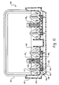
Figure 1C the sectional view indicated by line1C-1C ofFigure 1B . -
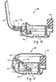
Figure 1D is the sectional view indicated by line 1D-1D ofFigure 1B . - Figure IE is the sectional view indicated by
line 1E-1E ofFigure 1B , showing the battery charger with a cover open. -
Figure 1F is the sectional view indicated byline 1E-1E ofFigure 1B , showing the battery charger with the cover closed. -
Figure 2 is a bottom view of a battery charger. -
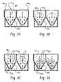
Figures 3A through 3D depict bays of a battery charger. -
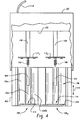
Figure 4 is a top view of a battery charger. -
Figure 5 is a top view of a battery charger. -
Figure 6 depicts a recessed battery contact. -
Figure 7 is a block diagram of a polarity agnostic charging circuit. -
Figure 8 depicts battery contact electrical connections. -
Figure 9 is a cross-sectional view of a battery tray. - With reference to
Figures 1A and1B , abattery charger 100 includes abody 102 and acover 104 which is mounted for pivotal motion relative to thebody 102 about a pivot orhinge axis 103.Figure 1A depicts thecover 104 in a closed position, whereasFigure 1B depicts the cover in an open position which allows a user to access abattery receiving region 106. In the illustrated embodiment, thebattery receiving region 106 includes five (5)battery receiving bays - The first through
fourth bays 1081-4 are configured to receive one or more generally cylindrical batteries having positive and negative terminals disposed on opposite ends of the battery. The batteries are received in thebays 1081-4 with their longitudinal axes extending generally in thedirection 110. Thebays 1081-4 each includemovable contact supports 1121-4 which are disposed generally toward the rear of therespective bays 1081-4. Thesupports 112 carryfirst battery contacts 132a,b,c (seeFigure 1 C) which are adapted to make electrical contact with the first terminals of the battery or batteries received in therespective bays 1081-4. Second, generallystationary battery contacts 1141-4, which are disposed generally toward the front of therespective bays 1081-4, are adapted to make electrical contact with the first terminal of the battery or batteries received in thebays 1081-4. - As will be described further below, the first 132 and second 114 battery contacts are zero insertion and removal force battery contacts. More specifically to the illustrated embodiment, the
contact supports 112 are in operative mechanical communication with thecover 104 so that, when the cover is in the open position, the spacing between thecontacts respective bays 1081-4. As a consequence, the batteries can be inserted in thebays 1081-4 without overcoming the contact force. When thecover 104 is in the closed position, the spacing between thecontacts contacts cover 104 again increases the spacing between thecontacts - The
fifth bay 1085 is configured to receive first 1161 and second 1162 generally rectangular nine volt (9V) batteries for charging. Suitable battery contacts disposed near the bottom of thefifth bay 1085 provide the requisite battery connections. Also disposed in thehousing 102 is conventional battery charging circuitry. Apower cord 118 connects thecharger 100 to a suitable power source, for example a wall cube which can be plugged into a standard alternating current (AC) power receptacle. An internally mounted, cover-actuated pushbutton switch automatically activates the charging circuitry when thecover 104 is closed, and a cover-mounteduser interface 120 such as a liquid crystal display (LCD) indicates the operational status of thecharger 100. - An exemplary one of the
bays 1081-4 will now be described with additional reference toFigures 1C and1D , it being understood that the first throughfourth bays 1081-4 are similarly configured. Note that the batteries depicted inFigure 1B have been omitted for ease of explanation. - The
bay 108 includes a first,rear end wall 122 and a second, spaced apartfront end wall 124. The distance between thewalls bay 108. - Disposed at the bottom of the
bay 108 is a battery tray which includes first 126a and second 126b outer battery supports and a third,central battery support 126c. The radii of the outer battery supports 126a, 126b are selected to support batteries having a relatively smaller radial dimension, for example standard AA and AAA size batteries. The radius of thecentral battery support 126c is slightly larger so as to additionally support batteries of a relatively larger radial dimension, for example standard C and D size batteries. - The
second battery contact 114, which is located at the second,front end wall 124, includes first 114a and second 114b outer battery contacts and a third,central battery contact 114c. Theouter contacts bay 108. Thecentral contact 114c is likewise positioned relative to thecentral battery support 126c so as to make contact with the second terminal of AAA, AA, C, and D size batteries. - The
contact support 112 is fabricated from a metallic or other conductive material. First 132a, second 132b, and third 132c contacts are formed as protrusions which make electrical contact with the first terminal of the battery or batteries received in thebay 108. Thecontact support 112 is mounted for slidable motion in aslot 138 formed in the battery tray. As will be appreciated, the direction of motion is generally parallel to thelongitudinal axes 110 of the battery or batteries. Aspring 140 connected between thecontact support 112 and the underside of the battery tray nearer to thefront end wall 114 urges thecontact support 112 toward thefront end wall 114. -
Figure 2 is a bottom view of thecharger 100 with the bottom cover removed for ease of explanation. Thecover 104 is pivotally attached to thehousing 102 via hinge pins 142 which are advantageously formed as an integral part of thecover 104 and which snappingly engage correspondingrecesses 144 in thebody 102. First 1461 and second 1462 slide members are disposed on the underside of the battery trays for slidable motion in thedirection 110. Therear portion 152 of theslide members 146 releasably engages front facingshoulders 154 formed on the contact supports 112. More specifically to the illustrated embodiment, thefirst slide member 1461 releasably engages the first 1121 and second 1122 contact supports, whereas thesecond slide member 1462 releasably engages the third 1123 and fourth 1124 contact supports. First 1481 and second 1482 link members are connected between thecover 104 and the respective first 1461 and second 1462 slide members. - With reference to
Figures 1E and 1F , a first end of eachlink members 148 is pivotally connected to the to thecover 104 for rotational motion about a pivot or hingeaxis 150, while the second end of eachlink member 148 is pivotally connected to arespective slide member 146 for rotational motion about a pivot or hingeaxis 152. - Opening the
cover 104 urges thelink members respective slide members battery receiving region 106. The rear 154 of theslide members 146 releasably engages theshoulders 156 of the respective contact supports 112, overcoming the force exerted by thesprings 140 and thus moving the contact supports 112 toward the rear of thebattery receiving region 106. Note that, when thecover 104 is in the open position, a line extending between thelink arm 148pivot axes springs 140 generates a moment about the pivot axis 130 which tends to maintain thecover 104 in the open position. - Closing the
cover 104 causes thelink members 148 and theslide members 146 to move toward the front of thebattery receiving region 106. As a consequence, thesprings 140 urge the contact supports 112 forward in coordination with the closing of thecover 104. If a battery is not installed in a givenbay 1081-4, thecontact support 112 moves forward to the limit of its travel. Where a battery (or batteries) is received in abay 1081-4, acontact 132 engages the first end the battery, thus urging it toward thesecond battery contact 114. When the second end of the battery contacts thesecond battery contact 114, thecontact support 112 is unable to move forward and thespring 140 applies a suitable contact force. The rear 154 of therespective slide member 146 disengages from theshoulder 156 of therespective contact support 112 so that thelink member 148 and theslide member 154 continue to move forward in coordination with the closing of thecover 104. - Pivoting the
cover 104 thus retracts each of themovable battery contacts 114, thus allowing the user to insert batteries in and/or remove batteries from the desiredbays 1081-4 with zero insertion or removal force. As will also be appreciated, the forward travel of the respective contact supports 1121-4 depends on the size of the battery or batteries received in itscorresponding bay 1081-4. As a result, the user may insert different size batteries in eachbay 1081-4. Thus, for example, a user may elect to insert a single C size battery in one of the bays, one or more AAA size batteries in another of the bays, a single D size battery in still another bay, one or more AA size batteries in the fourth bay. Of course, the foregoing is but one possibility, and other combinations are possible. - Still other variations are contemplated. For example, one or more of the
bays 1081-4 may be configured to selectively receive a single D size battery, a single C size battery, up to four (4) AA size batteries, or up to four (4) AAA size batteries. The battery supports and contact configuration of a device having two (2)such bays Figures 3A-3D . - An
exemplary bay 108 will now be described, it being understood that the first 1081 andsecond bays 1082 are similarly configured. Thebay 108 includes abattery support 302 having a generally funnel or V-shaped section. With reference toFigure 3A , thebattery support 302 supports a D-size battery 304 so that its longitudinal axis is positioned at the horizontal center of thebay 108. Abattery contact 114D is positioned relative to thebattery support 302 so as to make electrical contact with the second terminal of thebattery 304. - With reference to
Figure 3B , thebattery support 302 also supports a C-size battery 306 so that its longitudinal axis is positioned at the horizontal center of thebay 108 and slightly below that of the D-size battery 304. Abattery contact 114C is positioned relative to thebattery support 302 so as to make electrical contact with the second terminal of thebattery 304. - Turning now to
Figure 3C , thebattery support 302 also supports up to four (4)AA size batteries 308 in a two (2) dimensional close packed array in which adjacent rows and columns are offset by one-half (1/2) the battery radial dimension R. A plurality ofbattery contacts 114AA are positioned relative to thebattery support 302 so as to make electrical contact with the second terminals of thebatteries 308. As can be seen, a centroid of the array is coincident with a horizontal center of the battery support. - With reference now to
Figure 3D , thebattery support 302 similarly supports up to four (4)AAA size batteries 310, again in a two (2) dimensional close packed array with adjacent rows and columns offset by the radius r of thebatteries 310. A plurality ofbattery contacts 114AAA are positioned relative to thebattery support 302 so as to make electrical contact with the second terminals of thebatteries 310. - The
contacts 132 are likewise configured to make electrical contact with the first terminals of therespective batteries various contacts 114 need not be physically or electrically discrete; some or all of them may be combined so as to provide the desired electrical connections. In one example, the Dsize battery contact 114D, the Csize battery contact 114C, one of the AAsize battery contacts 114AA, and one of the AAAsize battery contacts 114AAA are combined in a single contact, and the remaining AAsize battery contacts 114AA and AAAsize battery contacts 114AAA are likewise combined in pair-wise fashion. Note also that one or more of thecontacts 132 may also be electrically discrete. - A particular advantage the arrangement described above is that the
battery support 302 tends to function as a hopper, thus using the force of gravity to funnel the battery or batteries inserted into abay 108 into their correct position(s). As a consequence, the batteries are largely self positioning, particularly when thebattery support 302 is used in combination with zero insertionforce battery contacts - Still other variations are contemplated. For example, one or more of the
bays 108 may be configured to receive only a single battery. Thus, abay 108 may be configured to receive a single D size battery, a single C size battery, a single AA size battery, or a single AAA size battery. In yet another alternative, one or more of thebays 108 may also be configured to receive multiple batteries of only a single size or of a relatively limited range of sizes. For example, abay 108 may be configured receive a plurality of AA or AAA batteries, or otherwise receive any two (2) or more battery sizes selected from the group of AAA, AA, C, and D-size batteries. Still other battery sizes are also contemplated. - Greater or lesser numbers of
bays 108 may also be provided. One or more of thebays 108 may also be provided with itsown cover 104. A givencover 104 may also actuate thecontacts 132 or more than one but less than all of thebays 108. A particular advantage of such arrangements is that they facilitate the independent operation of thevarious bays 108, for example where the user wishes to insert batteries in or remove batteries from a first bay while the batteries in another bay continue to charge. - The
contacts cover 104 is in the open position, the spacing between thecontacts bay 108. As will be appreciated, such an arrangement simplifies insertion and removal of the batteries, especially compared to arrangements in which the contact supports 112 must be grasped and moved by the user. Thecontacts - In another alternative implementation, one or more of the
bays 108 is provided with a lever which operates similarly to thecover 104. The lever may also be configured as a thumbwheel. In still another implementation, themovable battery contacts 112 may be actuated by a user operated slider accessible from the top of thecharger 100, with a detent holding the slider in the open or retracted position. -
Various link member 148 andslide member 146 implementations are also contemplated. For example, three (3) or more bays may share acommon link member 148; alink member 148 may be provided in connection with eachbay 108. The slide member ormembers 146 may be also be omitted, with a protrusion, pin, or the like extending from thelink member 148 and engaging the movingbattery contact 114. - The foregoing discussion has focused on an arrangement in which the battery trays are substantially stationary with respect to the
body 102. Turning now toFigure 4 , acharger 100 includes a generally sliding ortelescoping tray 402 located at the front of thecharger 100 and which is movable relative to thebody 102 in thedirection 110. Themovable battery contacts 112 are likewise movable in thedirection 110 in theslots 138, withsprings 140 urging themovable contacts 140 toward the front of thebody 102. Suitable material free regions orslots 404 provided in thetray 402 provide clearance for themovable contacts 112 and/or thesprings 140. In one implementation, thetray 402 is actuated manually by the user, with a suitable latch maintaining thetray 402 in the closed position. In another implementation, the tray is motorized. - With the
tray 402 in the open position (as shown inFigure 4 ), thesprings 140 urge themovable battery contacts 112 toward the front of thecharger 100. Where a battery (or batteries) is received in abay 108, closing thetray 402 causes the first end of the battery to engage thecorresponding contact support 112. If the second end of the battery is not already in contact with the front end wall 124 (or thecontacts 114, as the case may be), themovable contact 114 tends to urge the battery forward. Upon reaching the front of thebay 108, the second end of the battery then causes thecontact support 112 to retract in coordination with the closing of thetray 402. - In another variation which is illustrated in
Figure 5 , the contact supports 112 may be carried by thetray 402, withsprings 140 urging the movable contact supports 112 toward the front of thetray 402. When thetray 402 is opened, one or more protrusion(s) or pin(s) 408 extending from the bottom or sides of thehousing 102 engage forward facing shoulders disposed on themovable contacts 112, thereby retracting them. When the cover is closed, thesprings 140 urge themovable contacts 112 forward in thetray 402. - According to yet another implementation, the first 112 and second 114 contacts are formed at the first 122 and second 124 ends of the
tray 402. Aspring 140 urges thetray 402 toward the closed position, while a detent holds thetray 402 in the open position. - Various electrical arrangements are also contemplated. For example, a separate charging channel may be provided each of the
bays 108. In one such implementation, the battery contacts of a given bay is connected to thebattery charging circuitry 802 as shown inFigure 8 . A particular advantage of such an arrangement is that the charging energy supplied to the outer batteries may be applied independently. However, it will also be appreciated that thesecond contacts 114a,b,c may also be connected together so that the outer batteries are connected electrically in parallel during charging. Similar connection schemes may also be implemented in connection with the arrangement ofFigure 3D , taking into account the relatively larger number of batteries. - As illustrated schematically in
Figure 6 , the first orsecond battery contacts 602 may be recessed in theirrespective support 604. Where a battery is inserted with the incorrect polarity, the negative battery terminal does not make electrical contact with the recessedcontact 602. As a consequence, charging energy is not applied with the incorrect polarity. - In still another arrangement, the
battery contacts battery contacts bay 108. - A block diagram of an exemplary polarity agnostic battery charging circuit is depicted in
Figure 7 . As shown atFigure 7 , the charging circuit includes apolarity detection circuit 702 andbattery charging circuitry 704. Thepolarity detection circuitry 702 determines the polarity of one or more of the batteries received in abay 108. Thebattery charging circuitry 704 applies the desired charging energy to the battery or batteries, with the polarity of the charging energy selected based on the detected battery polarity. Various polarity detection techniques are known in the art and can be selected based on application specific requirements. In such a configuration, the respective first 132 and second 114 battery contacts for the various batteries in a givenbay 108 are not electrically connected so that the polarity of each battery may be individually detected and accounted for. -
Figure 9 is a cross sectional view of an alternate implementation of abattery tray 126 for anexemplary bay 108. Thetray 126 is depicted generally at the position of section 1D-1D shown inFigure 1 . The tray includes first 902a and 902c second outer battery supports which are dimensioned to support AAA size batteries. Additional outer supports 904a, 904b are likewise dimensioned to support a pair of relatively larger AA size batteries. Acentral region 906 includes a pair of upstanding, spaced apartprotrusions surface 912. Thus, the batteries are supported substantially along two (2) lines defined by theprotrusions protrusions surface 912. It should also be noted that, as illustrated, thebay 108 will concurrently accept up to three (3) AAA or AA size batteries, with one (1) battery disposed in each of the outer positions and a third battery disposed in the central position. - It should also noted that the above described techniques are not limited to use with battery chargers and may also be used in connection with battery powered electrical devices.
Claims (9)
- An apparatus including:a body (102);a first cover (104) mounted for pivotal motion relative to the body (102), wherein the first cover (104) pivots between an open position for inserting at least a first battery in a battery receiving region of the apparatus and a second position characterized in thata first pair of battery contacts (132a, 114) is in operative mechanical communication with the first cover (104), wherein pivoting the first cover (104) to the open position allows a first battery to be inserted between the first pair of battery contacts (132a, 114) with substantially zero insertion force and pivoting the cover (104) to the second position causes the first pair of battery contacts (132a, 114) to apply a contact force to terminals of the first battery.
- The apparatus of claim 1 including a first link member (148) in operative mechanical communication with the first cover (104) for releasably urging one (132a) of the first pair of contacts away from the other (114) of the first pair of contacts.
- The apparatus of claim 2 including a spring (140) for urging the one (132a) of the first pair of contacts toward the other (114) of the first pair of contacts.
- The apparatus of claim 2 including a second pair of battery contacts in operative mechanical communication with the first link member (148), wherein pivoting the cover (104) to the open position allows a second battery to be inserted between the first pair of battery contacts with substantially zero insertion force and pivoting the cover to the second position causes the first pair of battery contacts (132, 114) to make electrical contact with first and second terminals of the second battery.
- The apparatus of claim 4 including a slide member (146) in operative mechanical communication with the first link member (148) for releasably urging one (132) of the first pair of contacts away from the other (114) of the first pair of contacts and one of the second pair of contacts away from the other pair of contacts to accommodate different size batteries.
- The apparatus of claim 1 including a battery bay (108) configured to receive exactly one, two, or three AAA size batteries, exactly one, two, or three AA size batteries, exactly one C size battery, or exactly one D size battery.
- The apparatus of claim 1 including a battery polarity detection circuit (702) which detects the polarity with which the first battery is disposed between the first and second battery contacts (132, 114).
- The apparatus of claim 1 including:a battery support (302) having a generally funnel shaped cross section and which supports four generally cylindrical batteries in a two dimensional close packed array;a plurality of zero insertion force battery contacts (132, 114) for making electrical contact with first and second terminals of the batteries.
- The apparatus of claim 8 wherein the plurality of contacts (132, 114) include contacts for making electrical contact with first and second terminals of AAA and AA size batteries.
Applications Claiming Priority (2)
| Application Number | Priority Date | Filing Date | Title |
|---|---|---|---|
| US11/543,555 US7764045B2 (en) | 2006-10-05 | 2006-10-05 | Battery charger |
| PCT/US2007/021268 WO2008045263A2 (en) | 2006-10-05 | 2007-10-03 | Battery charger |
Publications (2)
| Publication Number | Publication Date |
|---|---|
| EP2070176A2 EP2070176A2 (en) | 2009-06-17 |
| EP2070176B1 true EP2070176B1 (en) | 2012-03-28 |
Family
ID=39146969
Family Applications (1)
| Application Number | Title | Priority Date | Filing Date |
|---|---|---|---|
| EP07839212A Not-in-force EP2070176B1 (en) | 2006-10-05 | 2007-10-03 | Battery charger |
Country Status (6)
| Country | Link |
|---|---|
| US (1) | US7764045B2 (en) |
| EP (1) | EP2070176B1 (en) |
| CN (2) | CN101523688B (en) |
| AT (1) | ATE551735T1 (en) |
| AU (1) | AU2007307183B2 (en) |
| WO (1) | WO2008045263A2 (en) |
Cited By (1)
| Publication number | Priority date | Publication date | Assignee | Title |
|---|---|---|---|---|
| WO2023097001A1 (en) * | 2021-11-24 | 2023-06-01 | Milwaukee Electric Tool Corporation | Work area charger |
Families Citing this family (16)
| Publication number | Priority date | Publication date | Assignee | Title |
|---|---|---|---|---|
| US8248029B2 (en) * | 2008-12-24 | 2012-08-21 | Frank Hrabal | Multi-functional rechargeable charger and power supply with dual direct current outputs |
| WO2012000570A1 (en) * | 2010-07-02 | 2012-01-05 | Sanofi-Aventis Deutschland Gmbh | Medical delivery device with battery compartment having elements facilitating battery insertion and removal |
| KR101192059B1 (en) * | 2011-04-13 | 2012-10-17 | 삼성에스디아이 주식회사 | Charging device with jig for charging of secondary battery |
| CN102231542B (en) * | 2011-06-24 | 2014-05-07 | 台达电子企业管理(上海)有限公司 | Battery charging device for electric vehicles |
| CN104733790A (en) * | 2013-12-21 | 2015-06-24 | 苏州宝时得电动工具有限公司 | Multi-battery-pack common discharge protection parameter setting method and overload protection method |
| US9768772B1 (en) | 2014-08-14 | 2017-09-19 | Amazon Technologies, Inc. | Polarity adaptive power source apparatus |
| CN105162216A (en) * | 2015-10-23 | 2015-12-16 | 诺鑫(南通)医疗技术有限公司 | Medical intelligent charging device top battery box interface device |
| FR3049402B1 (en) * | 2016-03-25 | 2020-01-10 | Continental Automotive France | UNIVERSAL INDUCTION RECHARGING SYSTEM FOR PORTABLE ELECTRONIC DEVICE |
| WO2018058459A1 (en) * | 2016-09-29 | 2018-04-05 | 深圳市大疆创新科技有限公司 | Charging base and charging kit |
| US11271410B2 (en) * | 2017-04-24 | 2022-03-08 | 9609385 Canada Inc. | Battery harvesting device and method |
| CN108023386A (en) * | 2017-12-29 | 2018-05-11 | 上海与德科技有限公司 | Intelligent recharge and discharge device and method |
| WO2020250087A1 (en) * | 2019-06-10 | 2020-12-17 | 3M Innovative Properties Company | Adapter for battery compartment |
| CN118991394A (en) * | 2020-03-17 | 2024-11-22 | 奥动新能源汽车科技有限公司 | Locking device, bracket assembly, electric automobile and battery box locking method |
| WO2022132706A1 (en) * | 2020-12-18 | 2022-06-23 | Milwaukee Electric Tool Corporation | Multi-bay battery charger |
| US12233978B2 (en) * | 2021-03-25 | 2025-02-25 | Shimano Inc. | Operating device for human-powered vehicle |
| CN117977748B (en) * | 2024-01-08 | 2025-10-24 | 福建南平南孚电池有限公司 | Battery charging system |
Family Cites Families (33)
| Publication number | Priority date | Publication date | Assignee | Title |
|---|---|---|---|---|
| US4546302A (en) | 1978-08-14 | 1985-10-08 | Century Mfg. Co. | Protective sensing means for battery charging circuit |
| JPS6113542U (en) | 1984-06-26 | 1986-01-27 | 東光株式会社 | Battery charging device |
| US4820965A (en) | 1987-03-23 | 1989-04-11 | Maurice A. Sween | Control circuit for battery charger |
| US4766361A (en) | 1987-09-23 | 1988-08-23 | General Electric Company | Battery charger having an interlocking assembly for accommodating increased charging rate capacity |
| US4876496A (en) | 1988-02-22 | 1989-10-24 | Allanson, Division Of Jannock Limited | Current supplying device |
| DE3827045A1 (en) | 1988-08-10 | 1990-02-22 | Ullmann Ulo Werk | POLE PROTECTION DEVICE FOR BATTERY CHARGERS |
| GB2240439A (en) | 1989-09-08 | 1991-07-31 | Link Sedan Limited | Battery charger |
| US5057761A (en) | 1990-01-11 | 1991-10-15 | Eveready Battery Company, Inc. | Means for distinguishing between batteries capable of being fast charged and other batteries and for charging same accordingly |
| US5072167A (en) | 1990-05-22 | 1991-12-10 | Acme Electric Corporation | Autopolarity battery charger |
| US5103155A (en) | 1990-11-30 | 1992-04-07 | Joannou Constantinos J | Battery charging cable system |
| US5184059A (en) | 1991-09-16 | 1993-02-02 | Motorola, Inc. | Expanded battery capacity identification scheme and apparatus |
| CN2131240Y (en) * | 1992-09-11 | 1993-04-28 | 耿向文 | Multifunctional charger |
| US5371455A (en) | 1993-10-08 | 1994-12-06 | Champion Freeze Drying Co., Ltd. | Control circuit for safe charging a rechargeable battery |
| US5486750A (en) | 1994-01-04 | 1996-01-23 | Walborn; Laverne A. | Battery charger with polarity sensing and timer |
| US5686808A (en) | 1995-05-31 | 1997-11-11 | Lutz; Frank T. | Universal battery charger and method |
| EP0806058A1 (en) | 1995-11-09 | 1997-11-12 | Rayovac Corporation | Compact battery charger |
| US5965998A (en) | 1996-07-02 | 1999-10-12 | Century Mfg. Co. | Automatic polarity and condition sensing battery charger |
| US6169387B1 (en) * | 1997-12-22 | 2001-01-02 | Lifecor, Inc. | Battery management apparatus for portable electronic devices |
| US5966821A (en) | 1998-01-12 | 1999-10-19 | Armbruster; Joseph M. | Storage canister for electric razor and shaving items |
| WO2000024108A1 (en) | 1998-10-16 | 2000-04-27 | Century Mfg. Co. | Portable battery charger including auto-polarity switch |
| GB2357641B (en) | 1999-12-20 | 2002-02-20 | Motorola Ltd | DC-DC Converter and energy management system |
| US6769787B2 (en) | 2000-10-11 | 2004-08-03 | Eveready Battery Company, Inc. | Flashlight |
| TW544986B (en) * | 2000-11-28 | 2003-08-01 | Delta Electronics Inc | Switchable battery charger |
| KR200225219Y1 (en) | 2000-12-28 | 2001-05-15 | 주식회사니카몬 | Charger |
| US6610941B2 (en) | 2001-10-02 | 2003-08-26 | Jdp Innovations Inc. | Battery size detector for a battery charger |
| DE20205135U1 (en) | 2002-04-03 | 2002-08-14 | FRIWO Gerätebau GmbH, 48346 Ostbevern | Charger |
| US6950030B2 (en) | 2002-09-05 | 2005-09-27 | Credo Technology Corporation | Battery charge indicating circuit |
| US6844705B2 (en) | 2002-12-09 | 2005-01-18 | Intersil Americas Inc. | Li-ion/Li-polymer battery charger configured to be DC-powered from multiple types of wall adapters |
| US6759833B1 (en) | 2003-05-06 | 2004-07-06 | Kuo-Hua Chen | Charger capable of switching polarity |
| TW595830U (en) | 2003-05-21 | 2004-06-21 | Iwei Technology Co Ltd | Structure improvement of polarity-less charger |
| US20050110467A1 (en) | 2003-11-03 | 2005-05-26 | Bon-Aire Industries, Inc. | Automotive jump starter with polarity detection and current routing circuitry |
| US20060071641A1 (en) | 2004-09-30 | 2006-04-06 | Ward Grahame P | Collapsible battery charger |
| KR101440740B1 (en) * | 2005-06-28 | 2014-09-18 | 스트리커 코포레이션 | Control assembly for a motorized surgical tool that contains a sensor that monitors the state of the motor rotor |
-
2006
- 2006-10-05 US US11/543,555 patent/US7764045B2/en active Active
-
2007
- 2007-10-03 CN CN2007800375072A patent/CN101523688B/en not_active Expired - Fee Related
- 2007-10-03 AT AT07839212T patent/ATE551735T1/en active
- 2007-10-03 WO PCT/US2007/021268 patent/WO2008045263A2/en not_active Ceased
- 2007-10-03 CN CN2007800374440A patent/CN101523687B/en not_active Expired - Fee Related
- 2007-10-03 EP EP07839212A patent/EP2070176B1/en not_active Not-in-force
- 2007-10-03 AU AU2007307183A patent/AU2007307183B2/en not_active Ceased
Cited By (1)
| Publication number | Priority date | Publication date | Assignee | Title |
|---|---|---|---|---|
| WO2023097001A1 (en) * | 2021-11-24 | 2023-06-01 | Milwaukee Electric Tool Corporation | Work area charger |
Also Published As
| Publication number | Publication date |
|---|---|
| ATE551735T1 (en) | 2012-04-15 |
| WO2008045263A2 (en) | 2008-04-17 |
| AU2007307183A1 (en) | 2008-04-17 |
| US20080084214A1 (en) | 2008-04-10 |
| AU2007307183B2 (en) | 2012-02-23 |
| HK1133331A1 (en) | 2010-03-19 |
| WO2008045263A3 (en) | 2008-05-29 |
| CN101523688B (en) | 2012-05-09 |
| CN101523687B (en) | 2012-02-29 |
| CN101523687A (en) | 2009-09-02 |
| CN101523688A (en) | 2009-09-02 |
| EP2070176A2 (en) | 2009-06-17 |
| US7764045B2 (en) | 2010-07-27 |
Similar Documents
| Publication | Publication Date | Title |
|---|---|---|
| EP2070176B1 (en) | Battery charger | |
| AU2007307184B2 (en) | Battery charger user interface | |
| US8274256B2 (en) | Battery charger | |
| US7999509B2 (en) | Universal charger for NiH and lithium batteries | |
| US5604050A (en) | Latching mechanism and method of latching thereby | |
| US20070241721A1 (en) | Direct current power supply | |
| US20060232243A1 (en) | Electrical appliance for use with batteries | |
| US20060001400A1 (en) | Battery charger with retention arms | |
| CN101076932B (en) | Folding type battery charger | |
| HK1133331B (en) | Battery charger | |
| US20110068748A1 (en) | Battery Power Routing Circuit | |
| EP2458706A1 (en) | Charging cradle | |
| WO2009145782A1 (en) | Battery power routing circuit |
Legal Events
| Date | Code | Title | Description |
|---|---|---|---|
| PUAI | Public reference made under article 153(3) epc to a published international application that has entered the european phase |
Free format text: ORIGINAL CODE: 0009012 |
|
| 17P | Request for examination filed |
Effective date: 20090320 |
|
| AK | Designated contracting states |
Kind code of ref document: A2 Designated state(s): AT BE BG CH CY CZ DE DK EE ES FI FR GB GR HU IE IS IT LI LT LU LV MC MT NL PL PT RO SE SI SK TR |
|
| AX | Request for extension of the european patent |
Extension state: AL BA HR MK RS |
|
| 17Q | First examination report despatched |
Effective date: 20090803 |
|
| DAX | Request for extension of the european patent (deleted) | ||
| REG | Reference to a national code |
Ref country code: HK Ref legal event code: DE Ref document number: 1133331 Country of ref document: HK |
|
| REG | Reference to a national code |
Ref country code: DE Ref legal event code: R079 Ref document number: 602007021671 Country of ref document: DE Free format text: PREVIOUS MAIN CLASS: H02J0007000000 Ipc: H01M0002040000 |
|
| GRAP | Despatch of communication of intention to grant a patent |
Free format text: ORIGINAL CODE: EPIDOSNIGR1 |
|
| RIC1 | Information provided on ipc code assigned before grant |
Ipc: H02J 7/00 20060101ALI20111026BHEP Ipc: H01M 2/04 20060101AFI20111026BHEP Ipc: H01M 10/44 20060101ALI20111026BHEP |
|
| GRAS | Grant fee paid |
Free format text: ORIGINAL CODE: EPIDOSNIGR3 |
|
| GRAA | (expected) grant |
Free format text: ORIGINAL CODE: 0009210 |
|
| AK | Designated contracting states |
Kind code of ref document: B1 Designated state(s): AT BE BG CH CY CZ DE DK EE ES FI FR GB GR HU IE IS IT LI LT LU LV MC MT NL PL PT RO SE SI SK TR |
|
| REG | Reference to a national code |
Ref country code: GB Ref legal event code: FG4D |
|
| REG | Reference to a national code |
Ref country code: CH Ref legal event code: EP |
|
| REG | Reference to a national code |
Ref country code: AT Ref legal event code: REF Ref document number: 551735 Country of ref document: AT Kind code of ref document: T Effective date: 20120415 |
|
| REG | Reference to a national code |
Ref country code: IE Ref legal event code: FG4D |
|
| REG | Reference to a national code |
Ref country code: DE Ref legal event code: R096 Ref document number: 602007021671 Country of ref document: DE Effective date: 20120524 |
|
| REG | Reference to a national code |
Ref country code: NL Ref legal event code: VDEP Effective date: 20120328 |
|
| PG25 | Lapsed in a contracting state [announced via postgrant information from national office to epo] |
Ref country code: LT Free format text: LAPSE BECAUSE OF FAILURE TO SUBMIT A TRANSLATION OF THE DESCRIPTION OR TO PAY THE FEE WITHIN THE PRESCRIBED TIME-LIMIT Effective date: 20120328 |
|
| LTIE | Lt: invalidation of european patent or patent extension |
Effective date: 20120328 |
|
| PG25 | Lapsed in a contracting state [announced via postgrant information from national office to epo] |
Ref country code: LV Free format text: LAPSE BECAUSE OF FAILURE TO SUBMIT A TRANSLATION OF THE DESCRIPTION OR TO PAY THE FEE WITHIN THE PRESCRIBED TIME-LIMIT Effective date: 20120328 Ref country code: GR Free format text: LAPSE BECAUSE OF FAILURE TO SUBMIT A TRANSLATION OF THE DESCRIPTION OR TO PAY THE FEE WITHIN THE PRESCRIBED TIME-LIMIT Effective date: 20120629 Ref country code: FI Free format text: LAPSE BECAUSE OF FAILURE TO SUBMIT A TRANSLATION OF THE DESCRIPTION OR TO PAY THE FEE WITHIN THE PRESCRIBED TIME-LIMIT Effective date: 20120328 |
|
| REG | Reference to a national code |
Ref country code: AT Ref legal event code: MK05 Ref document number: 551735 Country of ref document: AT Kind code of ref document: T Effective date: 20120328 |
|
| PG25 | Lapsed in a contracting state [announced via postgrant information from national office to epo] |
Ref country code: CY Free format text: LAPSE BECAUSE OF FAILURE TO SUBMIT A TRANSLATION OF THE DESCRIPTION OR TO PAY THE FEE WITHIN THE PRESCRIBED TIME-LIMIT Effective date: 20120328 |
|
| PG25 | Lapsed in a contracting state [announced via postgrant information from national office to epo] |
Ref country code: PL Free format text: LAPSE BECAUSE OF FAILURE TO SUBMIT A TRANSLATION OF THE DESCRIPTION OR TO PAY THE FEE WITHIN THE PRESCRIBED TIME-LIMIT Effective date: 20120328 Ref country code: SE Free format text: LAPSE BECAUSE OF FAILURE TO SUBMIT A TRANSLATION OF THE DESCRIPTION OR TO PAY THE FEE WITHIN THE PRESCRIBED TIME-LIMIT Effective date: 20120328 Ref country code: IS Free format text: LAPSE BECAUSE OF FAILURE TO SUBMIT A TRANSLATION OF THE DESCRIPTION OR TO PAY THE FEE WITHIN THE PRESCRIBED TIME-LIMIT Effective date: 20120728 Ref country code: RO Free format text: LAPSE BECAUSE OF FAILURE TO SUBMIT A TRANSLATION OF THE DESCRIPTION OR TO PAY THE FEE WITHIN THE PRESCRIBED TIME-LIMIT Effective date: 20120328 Ref country code: CZ Free format text: LAPSE BECAUSE OF FAILURE TO SUBMIT A TRANSLATION OF THE DESCRIPTION OR TO PAY THE FEE WITHIN THE PRESCRIBED TIME-LIMIT Effective date: 20120328 Ref country code: EE Free format text: LAPSE BECAUSE OF FAILURE TO SUBMIT A TRANSLATION OF THE DESCRIPTION OR TO PAY THE FEE WITHIN THE PRESCRIBED TIME-LIMIT Effective date: 20120328 Ref country code: SI Free format text: LAPSE BECAUSE OF FAILURE TO SUBMIT A TRANSLATION OF THE DESCRIPTION OR TO PAY THE FEE WITHIN THE PRESCRIBED TIME-LIMIT Effective date: 20120328 |
|
| REG | Reference to a national code |
Ref country code: HK Ref legal event code: GR Ref document number: 1133331 Country of ref document: HK |
|
| PG25 | Lapsed in a contracting state [announced via postgrant information from national office to epo] |
Ref country code: PT Free format text: LAPSE BECAUSE OF FAILURE TO SUBMIT A TRANSLATION OF THE DESCRIPTION OR TO PAY THE FEE WITHIN THE PRESCRIBED TIME-LIMIT Effective date: 20120730 Ref country code: SK Free format text: LAPSE BECAUSE OF FAILURE TO SUBMIT A TRANSLATION OF THE DESCRIPTION OR TO PAY THE FEE WITHIN THE PRESCRIBED TIME-LIMIT Effective date: 20120328 |
|
| PG25 | Lapsed in a contracting state [announced via postgrant information from national office to epo] |
Ref country code: DK Free format text: LAPSE BECAUSE OF FAILURE TO SUBMIT A TRANSLATION OF THE DESCRIPTION OR TO PAY THE FEE WITHIN THE PRESCRIBED TIME-LIMIT Effective date: 20120328 Ref country code: AT Free format text: LAPSE BECAUSE OF FAILURE TO SUBMIT A TRANSLATION OF THE DESCRIPTION OR TO PAY THE FEE WITHIN THE PRESCRIBED TIME-LIMIT Effective date: 20120328 Ref country code: NL Free format text: LAPSE BECAUSE OF FAILURE TO SUBMIT A TRANSLATION OF THE DESCRIPTION OR TO PAY THE FEE WITHIN THE PRESCRIBED TIME-LIMIT Effective date: 20120328 |
|
| PLBE | No opposition filed within time limit |
Free format text: ORIGINAL CODE: 0009261 |
|
| STAA | Information on the status of an ep patent application or granted ep patent |
Free format text: STATUS: NO OPPOSITION FILED WITHIN TIME LIMIT |
|
| PG25 | Lapsed in a contracting state [announced via postgrant information from national office to epo] |
Ref country code: IT Free format text: LAPSE BECAUSE OF FAILURE TO SUBMIT A TRANSLATION OF THE DESCRIPTION OR TO PAY THE FEE WITHIN THE PRESCRIBED TIME-LIMIT Effective date: 20120328 |
|
| 26N | No opposition filed |
Effective date: 20130103 |
|
| REG | Reference to a national code |
Ref country code: DE Ref legal event code: R097 Ref document number: 602007021671 Country of ref document: DE Effective date: 20130103 |
|
| PG25 | Lapsed in a contracting state [announced via postgrant information from national office to epo] |
Ref country code: ES Free format text: LAPSE BECAUSE OF FAILURE TO SUBMIT A TRANSLATION OF THE DESCRIPTION OR TO PAY THE FEE WITHIN THE PRESCRIBED TIME-LIMIT Effective date: 20120709 |
|
| PG25 | Lapsed in a contracting state [announced via postgrant information from national office to epo] |
Ref country code: MC Free format text: LAPSE BECAUSE OF NON-PAYMENT OF DUE FEES Effective date: 20121031 |
|
| REG | Reference to a national code |
Ref country code: CH Ref legal event code: PL |
|
| REG | Reference to a national code |
Ref country code: IE Ref legal event code: MM4A |
|
| PG25 | Lapsed in a contracting state [announced via postgrant information from national office to epo] |
Ref country code: IE Free format text: LAPSE BECAUSE OF NON-PAYMENT OF DUE FEES Effective date: 20121003 Ref country code: BG Free format text: LAPSE BECAUSE OF FAILURE TO SUBMIT A TRANSLATION OF THE DESCRIPTION OR TO PAY THE FEE WITHIN THE PRESCRIBED TIME-LIMIT Effective date: 20120628 Ref country code: CH Free format text: LAPSE BECAUSE OF NON-PAYMENT OF DUE FEES Effective date: 20121031 Ref country code: LI Free format text: LAPSE BECAUSE OF NON-PAYMENT OF DUE FEES Effective date: 20121031 |
|
| PG25 | Lapsed in a contracting state [announced via postgrant information from national office to epo] |
Ref country code: MT Free format text: LAPSE BECAUSE OF FAILURE TO SUBMIT A TRANSLATION OF THE DESCRIPTION OR TO PAY THE FEE WITHIN THE PRESCRIBED TIME-LIMIT Effective date: 20120328 |
|
| PG25 | Lapsed in a contracting state [announced via postgrant information from national office to epo] |
Ref country code: TR Free format text: LAPSE BECAUSE OF FAILURE TO SUBMIT A TRANSLATION OF THE DESCRIPTION OR TO PAY THE FEE WITHIN THE PRESCRIBED TIME-LIMIT Effective date: 20120328 |
|
| PG25 | Lapsed in a contracting state [announced via postgrant information from national office to epo] |
Ref country code: LU Free format text: LAPSE BECAUSE OF NON-PAYMENT OF DUE FEES Effective date: 20121003 |
|
| PG25 | Lapsed in a contracting state [announced via postgrant information from national office to epo] |
Ref country code: HU Free format text: LAPSE BECAUSE OF FAILURE TO SUBMIT A TRANSLATION OF THE DESCRIPTION OR TO PAY THE FEE WITHIN THE PRESCRIBED TIME-LIMIT Effective date: 20071003 |
|
| PGFP | Annual fee paid to national office [announced via postgrant information from national office to epo] |
Ref country code: DE Payment date: 20141029 Year of fee payment: 8 Ref country code: GB Payment date: 20141027 Year of fee payment: 8 Ref country code: FR Payment date: 20141017 Year of fee payment: 8 |
|
| PGFP | Annual fee paid to national office [announced via postgrant information from national office to epo] |
Ref country code: BE Payment date: 20141027 Year of fee payment: 8 |
|
| REG | Reference to a national code |
Ref country code: DE Ref legal event code: R119 Ref document number: 602007021671 Country of ref document: DE |
|
| GBPC | Gb: european patent ceased through non-payment of renewal fee |
Effective date: 20151003 |
|
| PG25 | Lapsed in a contracting state [announced via postgrant information from national office to epo] |
Ref country code: DE Free format text: LAPSE BECAUSE OF NON-PAYMENT OF DUE FEES Effective date: 20160503 Ref country code: GB Free format text: LAPSE BECAUSE OF NON-PAYMENT OF DUE FEES Effective date: 20151003 |
|
| REG | Reference to a national code |
Ref country code: FR Ref legal event code: ST Effective date: 20160630 |
|
| PG25 | Lapsed in a contracting state [announced via postgrant information from national office to epo] |
Ref country code: FR Free format text: LAPSE BECAUSE OF NON-PAYMENT OF DUE FEES Effective date: 20151102 |
|
| PG25 | Lapsed in a contracting state [announced via postgrant information from national office to epo] |
Ref country code: BE Free format text: LAPSE BECAUSE OF NON-PAYMENT OF DUE FEES Effective date: 20151031 |