EP2069987B1 - Base station for use in mri comprising a detachable display unit - Google Patents
Base station for use in mri comprising a detachable display unit Download PDFInfo
- Publication number
- EP2069987B1 EP2069987B1 EP07797406.1A EP07797406A EP2069987B1 EP 2069987 B1 EP2069987 B1 EP 2069987B1 EP 07797406 A EP07797406 A EP 07797406A EP 2069987 B1 EP2069987 B1 EP 2069987B1
- Authority
- EP
- European Patent Office
- Prior art keywords
- display unit
- stanchion
- patient
- base station
- unit
- Prior art date
- Legal status (The legal status is an assumption and is not a legal conclusion. Google has not performed a legal analysis and makes no representation as to the accuracy of the status listed.)
- Active
Links
Images


Classifications
-
- G—PHYSICS
- G01—MEASURING; TESTING
- G01R—MEASURING ELECTRIC VARIABLES; MEASURING MAGNETIC VARIABLES
- G01R33/00—Arrangements or instruments for measuring magnetic variables
- G01R33/20—Arrangements or instruments for measuring magnetic variables involving magnetic resonance
- G01R33/28—Details of apparatus provided for in groups G01R33/44 - G01R33/64
-
- A—HUMAN NECESSITIES
- A61—MEDICAL OR VETERINARY SCIENCE; HYGIENE
- A61B—DIAGNOSIS; SURGERY; IDENTIFICATION
- A61B5/00—Measuring for diagnostic purposes; Identification of persons
- A61B5/0002—Remote monitoring of patients using telemetry, e.g. transmission of vital signals via a communication network
- A61B5/0015—Remote monitoring of patients using telemetry, e.g. transmission of vital signals via a communication network characterised by features of the telemetry system
- A61B5/002—Monitoring the patient using a local or closed circuit, e.g. in a room or building
-
- A—HUMAN NECESSITIES
- A61—MEDICAL OR VETERINARY SCIENCE; HYGIENE
- A61B—DIAGNOSIS; SURGERY; IDENTIFICATION
- A61B5/00—Measuring for diagnostic purposes; Identification of persons
- A61B5/05—Detecting, measuring or recording for diagnosis by means of electric currents or magnetic fields; Measuring using microwaves or radio waves
- A61B5/055—Detecting, measuring or recording for diagnosis by means of electric currents or magnetic fields; Measuring using microwaves or radio waves involving electronic [EMR] or nuclear [NMR] magnetic resonance, e.g. magnetic resonance imaging
-
- A—HUMAN NECESSITIES
- A61—MEDICAL OR VETERINARY SCIENCE; HYGIENE
- A61B—DIAGNOSIS; SURGERY; IDENTIFICATION
- A61B5/00—Measuring for diagnostic purposes; Identification of persons
- A61B5/72—Signal processing specially adapted for physiological signals or for diagnostic purposes
- A61B5/7203—Signal processing specially adapted for physiological signals or for diagnostic purposes for noise prevention, reduction or removal
-
- G—PHYSICS
- G06—COMPUTING OR CALCULATING; COUNTING
- G06F—ELECTRIC DIGITAL DATA PROCESSING
- G06F1/00—Details not covered by groups G06F3/00 - G06F13/00 and G06F21/00
- G06F1/16—Constructional details or arrangements
- G06F1/1613—Constructional details or arrangements for portable computers
- G06F1/163—Wearable computers, e.g. on a belt
-
- A—HUMAN NECESSITIES
- A61—MEDICAL OR VETERINARY SCIENCE; HYGIENE
- A61B—DIAGNOSIS; SURGERY; IDENTIFICATION
- A61B5/00—Measuring for diagnostic purposes; Identification of persons
- A61B5/02—Detecting, measuring or recording for evaluating the cardiovascular system, e.g. pulse, heart rate, blood pressure or blood flow
- A61B5/024—Measuring pulse rate or heart rate
-
- A—HUMAN NECESSITIES
- A61—MEDICAL OR VETERINARY SCIENCE; HYGIENE
- A61B—DIAGNOSIS; SURGERY; IDENTIFICATION
- A61B5/00—Measuring for diagnostic purposes; Identification of persons
- A61B5/08—Measuring devices for evaluating the respiratory organs
- A61B5/0816—Measuring devices for examining respiratory frequency
-
- A—HUMAN NECESSITIES
- A61—MEDICAL OR VETERINARY SCIENCE; HYGIENE
- A61B—DIAGNOSIS; SURGERY; IDENTIFICATION
- A61B5/00—Measuring for diagnostic purposes; Identification of persons
- A61B5/145—Measuring characteristics of blood in vivo, e.g. gas concentration or pH-value ; Measuring characteristics of body fluids or tissues, e.g. interstitial fluid or cerebral tissue
-
- A—HUMAN NECESSITIES
- A61—MEDICAL OR VETERINARY SCIENCE; HYGIENE
- A61N—ELECTROTHERAPY; MAGNETOTHERAPY; RADIATION THERAPY; ULTRASOUND THERAPY
- A61N1/00—Electrotherapy; Circuits therefor
- A61N1/18—Applying electric currents by contact electrodes
- A61N1/32—Applying electric currents by contact electrodes alternating or intermittent currents
- A61N1/36—Applying electric currents by contact electrodes alternating or intermittent currents for stimulation
- A61N1/362—Heart stimulators
- A61N1/37—Monitoring; Protecting
- A61N1/3718—Monitoring of or protection against external electromagnetic fields or currents
-
- H—ELECTRICITY
- H02—GENERATION; CONVERSION OR DISTRIBUTION OF ELECTRIC POWER
- H02J—ELECTRIC POWER NETWORKS; CIRCUIT ARRANGEMENTS OR SYSTEMS FOR SUPPLYING OR DISTRIBUTING ELECTRIC POWER; SYSTEMS FOR STORING ELECTRIC ENERGY
- H02J2105/00—Networks for supplying or distributing electric power characterised by their spatial reach or by the load
- H02J2105/40—Networks for supplying or distributing electric power characterised by their spatial reach or by the load characterised by the loads connecting to the networks or being supplied by the networks
- H02J2105/46—Medical devices, medical implants or life supporting devices
-
- H—ELECTRICITY
- H02—GENERATION; CONVERSION OR DISTRIBUTION OF ELECTRIC POWER
- H02J—ELECTRIC POWER NETWORKS; CIRCUIT ARRANGEMENTS OR SYSTEMS FOR SUPPLYING OR DISTRIBUTING ELECTRIC POWER; SYSTEMS FOR STORING ELECTRIC ENERGY
- H02J7/00—Circuit arrangements for charging or discharging batteries or for supplying loads from batteries
- H02J7/34—Parallel operation in networks using both storage and other DC sources, e.g. providing buffering
- H02J7/345—Parallel operation in networks using both storage and other DC sources, e.g. providing buffering using capacitors as storage or buffering devices
-
- H—ELECTRICITY
- H02—GENERATION; CONVERSION OR DISTRIBUTION OF ELECTRIC POWER
- H02J—ELECTRIC POWER NETWORKS; CIRCUIT ARRANGEMENTS OR SYSTEMS FOR SUPPLYING OR DISTRIBUTING ELECTRIC POWER; SYSTEMS FOR STORING ELECTRIC ENERGY
- H02J7/00—Circuit arrangements for charging or discharging batteries or for supplying loads from batteries
- H02J7/50—Circuit arrangements for charging or discharging batteries or for supplying loads from batteries acting upon multiple batteries simultaneously or sequentially
Definitions
- the present invention relates generally to electronic patient monitors and to a detachable display unit suitable for use in the severe electromagnetic environment of a magnetic resonance imaging (MRI) machine as defined by claim 1.
- MRI magnetic resonance imaging
- Magnetic resonance imaging allows images to be created of soft tissue from faint electrical resonance (NMR) signals emitted by nuclei of the tissue.
- the resonance signals are generated when the tissue is subjected to a strong magnetic field and excited by a radiofrequency pulse.
- a patient undergoing an MRI scan may be received into a relatively narrow bore, or cavity, in the MRI magnet.
- the patient may be remotely monitored to determine, for example, heartbeat, respiration, temperature and blood oxygen.
- a typical remote monitoring system provides an "in-bore" patient sensor near the patient connected by electrical or optical cables or by RF data link to a base unit outside of the bore of the MRI magnet.
- the base unit customarily includes a display unit that may be consulted before the MRI scan to ensure that the monitoring sensors, for example, ECG leads or blood pressure cuffs are properly positioned and functioning.
- the monitoring sensors for example, ECG leads or blood pressure cuffs are properly positioned and functioning.
- the control room is normally separated from the MRI room holding the MRI magnet, and provides consoles and terminals for the MRI machine that allow control of the machine and the display of images from the MRI scan.
- the inventions described in these applications overcome problems of the electrically noisy environment of the MRI, such as would normally be expected to interfere with radio communications, by using combined diversity techniques including: frequency diversity, antenna location diversity, antenna polarization diversity, and time diversity in the transmitted signals.
- the quality of the signals is monitored to select among diverse pathways, dynamically allowing low error rates and high bandwidth at practical transmission powers.
- US 5,733,247 relates to a MR compatible monitoring system having a fiber optic data link between the patient monitor and the control room display/keyboard in a magnetic resonance imaging suite to allow for continuous monitoring of a patient's vital signs.
- US 6,246,573 relates to a wall mounted computer for use in an examining room or operatory such as employed in a dentist's or doctor's office., wherein a flat panel display is removably mounted on an articulated post to the metal box. The flat panel display may be viewed while mounted on the post, or may be removed for more convenient viewing by a patient or by medical personnel.
- US 2004/0147818 relates to a system, housed as a portable monitoring unit, monitoring and processing signal parameters acquired from a patient in multiple operational modes.
- a data acquisition processor receives patient parameter data from a plurality of different patient attached sensors and processes that data to provide processed patient parameter data.
- An image reproduction device displays processed patient parameter data.
- a communication interface communicates the processed patient parameter data to the image reproduction device for display and concurrently communicates the processed patient parameter data to either a docking station when said portable monitoring unit is docked in said docking station in a first mode or a network access point coupled to a communication network via wireless communication in a second mode.
- a power unit re-charges a battery in the portable monitoring unit in the first mode.
- the present invention is generally directed to a base unit having a display that may be detached and used remotely allowing continuous, yet flexible, monitoring of the patient, both near the bore and at other locations without the need for separate displays.
- the base unit may operate as a repeater to transmit information received from the wireless units in the bore to a remote location where the display is located.
- the display unit may also operate to transmit information wirelessly to the wireless units in the bore.
- a magnet-hardened display may allow the repositioning of the display at points closer to the magnet bore than would normally be possible with the base unit.
- the display unit may be docked to the base unit or other docking stations, such as a wall dock.
- Fig. 1 is a perspective view of an MRI suite showing the MRI magnet with a patient positioned for scanning and connected to a patient sensor, the latter communicating with a base unit positioned within the MRI room away from the bore of the magnet, and further showing a control room outside of the MRI suite shielded from the MRI suite against radiofrequency interference;
- Fig. 2 is a detailed view of a "hot shoe” attached to a pole supporting the display unit, the hot shoe removably holding a display associated with the base unit and providing power to that display;
- Fig. 3 is a block diagram of the base unit showing electrical connections through the hot shoe between a power supply of the base unit and the display;
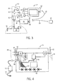
- Fig. 4 is a block diagram of the display of Fig. 3 , incorporating a magnet-hardened power supply offering several power supply options during local or remote connection;
- Fig. 5 is a figure similar to that of Fig. 4 showing the principal components of the base unit, including a computer and a port for the attachment of local displays and keyboard devices;
- Fig. 6 is a block diagram of a second embodiment of the hot shoe transmitting, not only electrical power, but also data communication;
- Fig. 7 is a flow chart of a program executed by the computer of Fig. 5 of the base unit in coordinating the communications between one or more of the patient sensor, base unit and the remote display.
- the present invention will be described with the wireless acquisition and transmission of physiological data to a remote display unit that is operative in the magnetic field generated by an MRI magnet. However, it is understood that the present invention may also be useful in other applications involving high-flux magnetic fields.
- a magnet room 10 provides radiofrequency, and possibly magnetic shielding, enclosing an MRI magnet 12.
- the magnet 12 may be part of an MRI machine controlled from a control room 16 providing a console 18 outside of the magnet room 10 and normally providing a shielded window 20 allowing viewing of the magnet 12 from the control room 16.
- a patient 14 may be positioned to be received into a bore 22 of the magnet 12 on a movable table 24 for an MRI scan. Before the scan, a wireless patient sensor or monitor 26 may be connected to the patient 14 to monitor patient physiological signals, including ECG, blood oxygen, blood pressure, and the like.
- the patient sensor 26 communicates via radio waves 28 to a base station 30 positioned outside the bore 22 of the magnet 12 using diversity techniques described in the above referenced co-pending patents.
- the base station 30 includes a monitor unit 32 and a display unit 34, both mounted on a stanchion 38, the latter extending upward from an optional wheeled base unit for easy movement.
- the monitor unit 32 receives wireless transmissions of data from the patient sensor 26, processes the same, and displays the data (or information associated therewith) on a graphic screen of the display unit 34.
- the display unit 34 may also include additional processing and user input controls, such as pressure-sensitive switches or a touch screen to provide commands to the monitor unit 32.
- the monitor unit 32 transmits the data on radio waves 36 implementing a different channel than the radio waves 28 received from the patient sensor(s) 26.
- a channel may refer to any combination of logical and physical channel parameters including, for example, frequency, frequency hop patterns, packet identifiers, and the like.
- Wireless transmission of data to the display unit 34 allows the display unit 34 to be located either on a dock, such as stanchion 38, or remotely located, per display unit 34', for example, on a stanchion or other dock in the control room 16. Alternately, the display unit may be docked on a wall or desk dock in the magnet room 10 or in the control room 16.
- the control room 16 is normally shielded from the magnet room 10 but may provide a passive or active repeater penetrating the shield and passing radio waves 36 used by the monitor unit 32.
- the display unit 34 may not only receive physiological data from the base station 30 but may also transmit commands to the base station 30 and, via the base station 30, to the patient sensors 26, for example, as input by an operator. Wireless communication eliminates the problem of cable management and allows the display unit 34 easy, and repeated detachability from the base station 30.
- a hot shoe 40 held by the stanchion 38, which may connect mechanically and electrically with a hot shoe socket 42 mounted on the rear surface of the display unit 34.
- the hot shoe 40 and the hot shoe socket 42 present a quick-connect connection for attaching or detaching the display unit from stanchion 38. Connecting the hot shoe 40 with the hot shoe socket 42 attaches the display unit 34 to the stanchion 38 or to another remotely located hot shoe (e.g., in the control room 16).
- the hot shoe 40 presents a plurality of direct current power contacts 44 that may connect with corresponding contacts 46 in the hot shoe socket 42.
- electrical contact may be had between individual pairs of contacts in 44 and 46.
- a switch operator 48 may protrude from the hot shoe 40 to be depressed by a surface of the hot shoe socket 42 when the hot shoe socket 42 is engaged with the hot shoe 40.
- the switch operator 48 closes a switch 50 to connect electrical power and/or ground to the contacts 44 so that power may be provided to the display unit 34 when it is attached to the stanchion 38, but so that power is not exposed on the contacts 44 when the display unit 34 has been removed.
- the terminal of the switch 50 not connected to one of the contacts 44 is connected to a radiofrequency filter 52 that, in turn, connects to the power side of a storage battery 54 held in the base of the stanchion 38.
- the filter 52 prevents electromagnetic interference picked up by the wiring of the stanchion 38 from being introduced into the display unit 34 and vice versa.
- the monitor unit 32 is also attached to the stanchion 38 and also internally connected to the battery 54.
- a charge jack 56 is on the base of the stanchion 38 accepting a charger "brick" (not shown) to provide charging current to the battery 54 and operating power to the display unit 34 and monitor unit 32.
- the display unit 34 also includes an internal battery (as will be described), which may be charged by the charger brick.
- the monitor unit 32 includes an antenna 58, which, as described above, allows it to communicate wirelessly with the patient sensor 26 on a first channel formed by radio waves 28 and with the display unit 34 through antenna 62 on a second channel formed by radio waves 36.
- the display unit 34 receives power through the hot shoe socket 42 at a special magnetically “hardened” power supply 66 in which a standard switching power supply circuit is modified by removal of "soft" ferrite or steel core transformers and replacing them with air core or "hard ferrite” core transformers that may operate without saturation in the environment of the high flux field of the MRI up to approximately 15,000 Gauss. In this way the display unit may operate in magnetic fields of up to 15,000 Gauss in strength.
- the power supply 66 may alternatively receive power directly through a charger jack 68 exposed at one side of the display unit 34 that may receive power from a charger brick 70, in turn having a standard line cord 72 for connecting to line power.
- charger brick 70 may also supply electrical power to the base station 30 directly through the interconnection of contacts 44 and 46.
- the power supply 66 When the power supply 66 is receiving power, it, in turn, provides power to a transmitter/receiver 76 connected to the antenna 62 and to control circuitry 78, which may include, for example, a processor, a digital signal processor implemented through discrete circuits or with a field programmable gate array (“FPGA").
- the control circuitry 78 may provide signals to a liquid crystal display (LCD) touch screen 80 (or an LCD and switch panel) allowing both the display of data and the acceptance of user commands.
- LCD liquid crystal display
- Power supply 66 may also provide power to a string of LEDs 82 allowing for backlighting of the LCD screen 80 without the need for cold cathode fluorescent tubes and their associated power supplies, which could produce unnecessary interference in the MRI environment and be inoperative in high field environments.
- the switching power supply 66 provides charging power to an internal battery 74 that may be used when the display unit 34 is in a roving mode not connected to the stanchion 38, but communicating with the base unit via the antenna 62.
- the display unit may have one or more supercapacitors to provide power to the internal electronic components of the display unit and charged in a known manner using an appropriate charger, when necessary.
- the monitor unit 32 may receive power through a direct connection 84 with the stanchion 38 at a power supply 86. Because the stanchion 38 is normally positioned away from the magnet 12 during an MRI examination, the monitor unit 32 may use standard switching power supply components to provide power to processing electronics 88 and transmitter/receiver 90, communicating with antenna 58 to receive information from the patient sensor 26 and to communicate with the display unit 34.
- the monitor unit 32 may also include a port system 92 providing for communication ports similar to those in a standard personal computer, allowing for the connection of a keyboard 94, a standard display, such as an LCD display 96 and a cursor control device, such as a mouse, 98. This allows the monitor unit 32 to be used independently of connection to the display unit 34.
- the hot shoe 40 also provides for a data connector 100, in addition to the power contacts 44.
- Data connector 100 is operationally connected to output data from or input data to the monitor unit 32.
- the hot shoe socket 42 may provide for a corresponding data connector 102 connecting with data connector 100.
- the data connectors 100 and 102 may, for example, provide for a parallel or serial digital connection of conductors or optical cable or the like, and provide for a path between the monitor unit 32 and the display unit 34 when the display unit 34 is docked on the stanchion 38.
- internal software may optionally disconnect the transmitter/receiver 76 in the display unit 34, thereby preventing the generation of unnecessary radiofrequency signals.
- the monitor unit 32 may suppress transmissions from the transmitter/receiver 90 to the display unit 34.
- Connectors 100 and 102 allow for the introduction of a jumper cable 104 of arbitrary length allowing a direct cable connection between the monitor unit 32 and display unit 34 for situations where a remote display is required on a semi or permanent basis.
- a remote semi -permanent display may be used in addition to the roving wirelessly- connected display unit 34.
- the processing electronics 88 may execute a stored program 106 coordinating the wireless communications between the monitor unit 32 and the display unit 34 by properly assigning channels to the communications permitting, for example, the use of multiple display units 34 with one monitor unit 32 or multiple monitor units 32 communicating with one display unit 34 without interference.
- a channel selection process is employed to logically connect a given monitor unit 32 with a given display unit 34.
- this commissioning process begins with the identification of a particular display unit 34 and monitor unit 32 by the entry of a display identifier or the like, and possibly the entry of a unique serial number or MAC address.
- a logical channel or network address is selected for the communication, such as will be provided to both the display unit 34 and monitor unit 32, either manually or by a default communication channel.
- a channel may refer to any combination of logical and physical channel parameters including, for example, frequency hop patterns, packet identifiers, and the like.
- the user may lock the channel selected, preventing inadvertent channel changes, such as may confuse the unique path between a particular patient 14 and a particular display unit 34, such as might permit a user to be misled about the source of particular signals. If the channel is not locked, then, at process block 114, the channel may be changed.
- decision block 112 the program jumps to decision block 116, which allows the lock state to change per process block 118, possibly requiring a password or the like.
Landscapes
- Health & Medical Sciences (AREA)
- Engineering & Computer Science (AREA)
- Life Sciences & Earth Sciences (AREA)
- Physics & Mathematics (AREA)
- Animal Behavior & Ethology (AREA)
- Veterinary Medicine (AREA)
- Public Health (AREA)
- General Health & Medical Sciences (AREA)
- Surgery (AREA)
- Biophysics (AREA)
- Pathology (AREA)
- Biomedical Technology (AREA)
- Heart & Thoracic Surgery (AREA)
- Medical Informatics (AREA)
- Molecular Biology (AREA)
- General Physics & Mathematics (AREA)
- Signal Processing (AREA)
- Nuclear Medicine, Radiotherapy & Molecular Imaging (AREA)
- Theoretical Computer Science (AREA)
- Computer Hardware Design (AREA)
- Human Computer Interaction (AREA)
- High Energy & Nuclear Physics (AREA)
- Physiology (AREA)
- Artificial Intelligence (AREA)
- General Engineering & Computer Science (AREA)
- Psychiatry (AREA)
- Computer Networks & Wireless Communication (AREA)
- Condensed Matter Physics & Semiconductors (AREA)
- Computer Vision & Pattern Recognition (AREA)
- Radiology & Medical Imaging (AREA)
- Magnetic Resonance Imaging Apparatus (AREA)
- Ultra Sonic Daignosis Equipment (AREA)
- Measuring And Recording Apparatus For Diagnosis (AREA)
- Battery Mounting, Suspending (AREA)
Abstract
Description
- The present invention relates generally to electronic patient monitors and to a detachable display unit suitable for use in the severe electromagnetic environment of a magnetic resonance imaging (MRI) machine as defined by claim 1.
- Magnetic resonance imaging allows images to be created of soft tissue from faint electrical resonance (NMR) signals emitted by nuclei of the tissue. The resonance signals are generated when the tissue is subjected to a strong magnetic field and excited by a radiofrequency pulse.
- A patient undergoing an MRI scan may be received into a relatively narrow bore, or cavity, in the MRI magnet. During this time, the patient may be remotely monitored to determine, for example, heartbeat, respiration, temperature and blood oxygen. A typical remote monitoring system provides an "in-bore" patient sensor near the patient connected by electrical or optical cables or by RF data link to a base unit outside of the bore of the MRI magnet.
- The base unit customarily includes a display unit that may be consulted before the MRI scan to ensure that the monitoring sensors, for example, ECG leads or blood pressure cuffs are properly positioned and functioning. During the scan, when it is critical that the patient be continuously monitored, one operator may be stationed near the base unit in the MRI room and another will attend to the control of the MRI machine in the control room. The control room is normally separated from the MRI room holding the MRI magnet, and provides consoles and terminals for the MRI machine that allow control of the machine and the display of images from the MRI scan.
- Conventional base units are cabled to the patient sensor in the bore of the magnet using optical or electrical cables. Such cable runs can be cumbersome and interfere with access to the patient and free movement of personnel about the magnet itself. This problem is addressed in pending
U.S. patent applications 11/080,958, filed March 15, 2005 , and11/080,743, filed March 15, 2005 - The inventions described in these applications overcome problems of the electrically noisy environment of the MRI, such as would normally be expected to interfere with radio communications, by using combined diversity techniques including: frequency diversity, antenna location diversity, antenna polarization diversity, and time diversity in the transmitted signals. The quality of the signals is monitored to select among diverse pathways, dynamically allowing low error rates and high bandwidth at practical transmission powers.
- Despite these diversity techniques, it may not be practical to transmit wirelessly from within the bore of the magnet into the control room, such as would allow the base unit to be repositioned in the control room itself to be monitored by the operator of the MRI machine. Accordingly, there is a need for a base unit operable in or near the MRI machine during an MRI examination. It would also be desirable to have a display unit detachable from the base unit that would enable an operator to roam with the display unit detached from the base unit, thereby allowing an operator to monitor the display unit remote from the base unit. It would also be desirable to control operation of a wireless patient monitoring system through inputs to the display unit that are wirelessly communicated to the base unit.
US 5,733,247 relates to a MR compatible monitoring system having a fiber optic data link between the patient monitor and the control room display/keyboard in a magnetic resonance imaging suite to allow for continuous monitoring of a patient's vital signs.
US 6,246,573 relates to a wall mounted computer for use in an examining room or operatory such as employed in a dentist's or doctor's office., wherein a flat panel display is removably mounted on an articulated post to the metal box. The flat panel display may be viewed while mounted on the post, or may be removed for more convenient viewing by a patient or by medical personnel.
US 2004/0147818 relates to a system, housed as a portable monitoring unit, monitoring and processing signal parameters acquired from a patient in multiple operational modes. A data acquisition processor receives patient parameter data from a plurality of different patient attached sensors and processes that data to provide processed patient parameter data. An image reproduction device displays processed patient parameter data. A communication interface communicates the processed patient parameter data to the image reproduction device for display and concurrently communicates the processed patient parameter data to either a docking station when said portable monitoring unit is docked in said docking station in a first mode or a network access point coupled to a communication network via wireless communication in a second mode. A power unit re-charges a battery in the portable monitoring unit in the first mode. - Therefore, it is an object of the present invention to provide a base unit of a MRI compatible patient monitor device allowing for maximum flexibility. The object is solved by the features of the independent claim.
- The present invention is generally directed to a base unit having a display that may be detached and used remotely allowing continuous, yet flexible, monitoring of the patient, both near the bore and at other locations without the need for separate displays. The base unit may operate as a repeater to transmit information received from the wireless units in the bore to a remote location where the display is located. The display unit may also operate to transmit information wirelessly to the wireless units in the bore. A magnet-hardened display may allow the repositioning of the display at points closer to the magnet bore than would normally be possible with the base unit. In one embodiment, the display unit may be docked to the base unit or other docking stations, such as a wall dock.
- Various other features, objects and advantages of the present invention will be made apparent from the following detailed description and the drawings.
- The drawings illustrate one preferred embodiment presently contemplated for carrying out the invention.
- In the drawings:
-
Fig. 1 is a perspective view of an MRI suite showing the MRI magnet with a patient positioned for scanning and connected to a patient sensor, the latter communicating with a base unit positioned within the MRI room away from the bore of the magnet, and further showing a control room outside of the MRI suite shielded from the MRI suite against radiofrequency interference; -
Fig. 2 is a detailed view of a "hot shoe" attached to a pole supporting the display unit, the hot shoe removably holding a display associated with the base unit and providing power to that display; -
Fig. 3 is a block diagram of the base unit showing electrical connections through the hot shoe between a power supply of the base unit and the display; -
Fig. 4 is a block diagram of the display ofFig. 3 , incorporating a magnet-hardened power supply offering several power supply options during local or remote connection; -
Fig. 5 is a figure similar to that ofFig. 4 showing the principal components of the base unit, including a computer and a port for the attachment of local displays and keyboard devices; -
Fig. 6 is a block diagram of a second embodiment of the hot shoe transmitting, not only electrical power, but also data communication; and -
Fig. 7 is a flow chart of a program executed by the computer ofFig. 5 of the base unit in coordinating the communications between one or more of the patient sensor, base unit and the remote display. - The present invention will be described with the wireless acquisition and transmission of physiological data to a remote display unit that is operative in the magnetic field generated by an MRI magnet. However, it is understood that the present invention may also be useful in other applications involving high-flux magnetic fields.
- Referring now to
Fig. 1 , amagnet room 10 provides radiofrequency, and possibly magnetic shielding, enclosing anMRI magnet 12. Themagnet 12 may be part of an MRI machine controlled from acontrol room 16 providing aconsole 18 outside of themagnet room 10 and normally providing a shieldedwindow 20 allowing viewing of themagnet 12 from thecontrol room 16. - A
patient 14 may be positioned to be received into abore 22 of themagnet 12 on a movable table 24 for an MRI scan. Before the scan, a wireless patient sensor ormonitor 26 may be connected to thepatient 14 to monitor patient physiological signals, including ECG, blood oxygen, blood pressure, and the like. - The
patient sensor 26 communicates viaradio waves 28 to abase station 30 positioned outside thebore 22 of themagnet 12 using diversity techniques described in the above referenced co-pending patents. Thebase station 30 includes amonitor unit 32 and adisplay unit 34, both mounted on astanchion 38, the latter extending upward from an optional wheeled base unit for easy movement. Generally, themonitor unit 32 receives wireless transmissions of data from thepatient sensor 26, processes the same, and displays the data (or information associated therewith) on a graphic screen of thedisplay unit 34. Thedisplay unit 34 may also include additional processing and user input controls, such as pressure-sensitive switches or a touch screen to provide commands to themonitor unit 32. - In communicating with the display unit, the
monitor unit 32 transmits the data onradio waves 36 implementing a different channel than theradio waves 28 received from the patient sensor(s) 26. In this case, a channel may refer to any combination of logical and physical channel parameters including, for example, frequency, frequency hop patterns, packet identifiers, and the like. Wireless transmission of data to thedisplay unit 34 allows thedisplay unit 34 to be located either on a dock, such asstanchion 38, or remotely located, per display unit 34', for example, on a stanchion or other dock in thecontrol room 16. Alternately, the display unit may be docked on a wall or desk dock in themagnet room 10 or in thecontrol room 16. Thecontrol room 16 is normally shielded from themagnet room 10 but may provide a passive or active repeater penetrating the shield and passingradio waves 36 used by themonitor unit 32. Thedisplay unit 34 may not only receive physiological data from thebase station 30 but may also transmit commands to thebase station 30 and, via thebase station 30, to thepatient sensors 26, for example, as input by an operator. Wireless communication eliminates the problem of cable management and allows thedisplay unit 34 easy, and repeated detachability from thebase station 30. - Referring now to
Figs. 2 and3 , freedom to relocate thedisplay unit 34 is provided by ahot shoe 40, held by thestanchion 38, which may connect mechanically and electrically with ahot shoe socket 42 mounted on the rear surface of thedisplay unit 34. Thehot shoe 40 and thehot shoe socket 42 present a quick-connect connection for attaching or detaching the display unit fromstanchion 38. Connecting thehot shoe 40 with thehot shoe socket 42 attaches thedisplay unit 34 to thestanchion 38 or to another remotely located hot shoe (e.g., in the control room 16). - The
hot shoe 40 presents a plurality of directcurrent power contacts 44 that may connect withcorresponding contacts 46 in thehot shoe socket 42. When thehot shoe socket 42 is engaged with thehot shoe 40, electrical contact may be had between individual pairs of contacts in 44 and 46. Aswitch operator 48 may protrude from thehot shoe 40 to be depressed by a surface of thehot shoe socket 42 when thehot shoe socket 42 is engaged with thehot shoe 40. Theswitch operator 48 closes aswitch 50 to connect electrical power and/or ground to thecontacts 44 so that power may be provided to thedisplay unit 34 when it is attached to thestanchion 38, but so that power is not exposed on thecontacts 44 when thedisplay unit 34 has been removed. - In a preferred embodiment of the invention, the terminal of the
switch 50 not connected to one of thecontacts 44 is connected to aradiofrequency filter 52 that, in turn, connects to the power side of astorage battery 54 held in the base of thestanchion 38. Thefilter 52 prevents electromagnetic interference picked up by the wiring of thestanchion 38 from being introduced into thedisplay unit 34 and vice versa. - The
monitor unit 32 is also attached to thestanchion 38 and also internally connected to thebattery 54. Acharge jack 56 is on the base of thestanchion 38 accepting a charger "brick" (not shown) to provide charging current to thebattery 54 and operating power to thedisplay unit 34 and monitorunit 32. Thedisplay unit 34 also includes an internal battery (as will be described), which may be charged by the charger brick. - The
monitor unit 32 includes anantenna 58, which, as described above, allows it to communicate wirelessly with thepatient sensor 26 on a first channel formed byradio waves 28 and with thedisplay unit 34 throughantenna 62 on a second channel formed byradio waves 36. - Referring now to
Fig. 4 , thedisplay unit 34 receives power through thehot shoe socket 42 at a special magnetically "hardened"power supply 66 in which a standard switching power supply circuit is modified by removal of "soft" ferrite or steel core transformers and replacing them with air core or "hard ferrite" core transformers that may operate without saturation in the environment of the high flux field of the MRI up to approximately 15,000 Gauss. In this way the display unit may operate in magnetic fields of up to 15,000 Gauss in strength. - The
power supply 66 may alternatively receive power directly through acharger jack 68 exposed at one side of thedisplay unit 34 that may receive power from acharger brick 70, in turn having astandard line cord 72 for connecting to line power. In addition,charger brick 70 may also supply electrical power to thebase station 30 directly through the interconnection ofcontacts - When the
power supply 66 is receiving power, it, in turn, provides power to a transmitter/receiver 76 connected to theantenna 62 and to controlcircuitry 78, which may include, for example, a processor, a digital signal processor implemented through discrete circuits or with a field programmable gate array ("FPGA"). Thecontrol circuitry 78 may provide signals to a liquid crystal display (LCD) touch screen 80 (or an LCD and switch panel) allowing both the display of data and the acceptance of user commands. -
Power supply 66 may also provide power to a string ofLEDs 82 allowing for backlighting of theLCD screen 80 without the need for cold cathode fluorescent tubes and their associated power supplies, which could produce unnecessary interference in the MRI environment and be inoperative in high field environments. - Finally, the switching
power supply 66 provides charging power to aninternal battery 74 that may be used when thedisplay unit 34 is in a roving mode not connected to thestanchion 38, but communicating with the base unit via theantenna 62. Alternately, or in addition thereof, the display unit may have one or more supercapacitors to provide power to the internal electronic components of the display unit and charged in a known manner using an appropriate charger, when necessary. - Referring now to
Fig. 5 , themonitor unit 32 may receive power through a direct connection 84 with thestanchion 38 at apower supply 86. Because thestanchion 38 is normally positioned away from themagnet 12 during an MRI examination, themonitor unit 32 may use standard switching power supply components to provide power to processingelectronics 88 and transmitter/receiver 90, communicating withantenna 58 to receive information from thepatient sensor 26 and to communicate with thedisplay unit 34. Themonitor unit 32 may also include aport system 92 providing for communication ports similar to those in a standard personal computer, allowing for the connection of akeyboard 94, a standard display, such as anLCD display 96 and a cursor control device, such as a mouse, 98. This allows themonitor unit 32 to be used independently of connection to thedisplay unit 34. - Referring now to
Fig. 6 , thehot shoe 40 also provides for adata connector 100, in addition to thepower contacts 44.Data connector 100 is operationally connected to output data from or input data to themonitor unit 32. Similarly, thehot shoe socket 42 may provide for acorresponding data connector 102 connecting withdata connector 100. Thedata connectors monitor unit 32 and thedisplay unit 34 when thedisplay unit 34 is docked on thestanchion 38. When theconnectors receiver 76 in thedisplay unit 34, thereby preventing the generation of unnecessary radiofrequency signals. Similarly, themonitor unit 32 may suppress transmissions from the transmitter/receiver 90 to thedisplay unit 34. -
Connectors jumper cable 104 of arbitrary length allowing a direct cable connection between themonitor unit 32 anddisplay unit 34 for situations where a remote display is required on a semi or permanent basis. By using thejumper cable 104, a remote semi -permanent display may be used in addition to the roving wirelessly- connecteddisplay unit 34. - Referring now to
Fig. 7 and Fig. 5 , theprocessing electronics 88 may execute a storedprogram 106 coordinating the wireless communications between themonitor unit 32 and thedisplay unit 34 by properly assigning channels to the communications permitting, for example, the use ofmultiple display units 34 with onemonitor unit 32 ormultiple monitor units 32 communicating with onedisplay unit 34 without interference. In order to provide for this unique connection between devices, a channel selection process is employed to logically connect a givenmonitor unit 32 with a givendisplay unit 34. - As indicated by
process block 108, this commissioning process begins with the identification of aparticular display unit 34 and monitorunit 32 by the entry of a display identifier or the like, and possibly the entry of a unique serial number or MAC address. - At
process block 110, a logical channel or network address is selected for the communication, such as will be provided to both thedisplay unit 34 and monitorunit 32, either manually or by a default communication channel. As before, a channel may refer to any combination of logical and physical channel parameters including, for example, frequency hop patterns, packet identifiers, and the like. - The user may lock the channel selected, preventing inadvertent channel changes, such as may confuse the unique path between a
particular patient 14 and aparticular display unit 34, such as might permit a user to be misled about the source of particular signals. If the channel is not locked, then, atprocess block 114, the channel may be changed. - If the channel is locked, then, at
decision block 112, the program jumps to decision block 116, which allows the lock state to change perprocess block 118, possibly requiring a password or the like. - It is specifically intended that the present invention not be limited to the embodiments and illustrations contained herein and the claims should be understood to include modified forms of those embodiments including portions of the embodiments and combinations of elements of different embodiments as come within the scope of the following claims.
Claims (7)
- A base station (30) for an MRI compatible patient monitor device, the base station positionable outside the bore (22) of the magnet (12) during an MRI examination and comprising:a monitor unit (32); anda display unit (34),characterized in thatthe monitor unit (32) is configured to receive wireless transmissions of data from a patient sensor (26) that acquires physiological signals from a patient; andthe display unit (34) adapted to be positionable remotely from the monitor unit (32) is capable of wireless communication with the monitor unit (32) to display information associated with the data received from the patient sensor (26) by the monitor unit (32), and is detachable from the base unit (30), andthe base station (30) further comprises a stanchion (38), wherein the stanchion (28) has a hot shoe (40) and the display unit (34) has a hot shoe socket (42) configured to interface with the hot shoe (40) when the display unit (34) is mounted to the stanchion (38),wherein the hot shoe (40) includes a first data connector (100) and the hot shoe socket (42) includes a second data connector (102), and wherein the monitor unit (32) transmits data to the display unit (34) through the first and second data connectors (100, 102) when the display unit (34) is mounted to the stanchion (38), andwherein the monitor unit (32) is configured to receive the wireless transmissions of data from the patient sensor (26) on radio waves (28) implementing a first channel and is further configured to transmit data to the display unit (34) on radio waves (36) implementing a second channel different from the first channel.
- The base station (30) of claim 1, wherein the hot shoe (40) comprises a first set of contacts (44) and the hot shoe socket (42) comprises a second set of contacts (46), and wherein the sets of contacts (44, 46) facilitate the transference of power from the stanchion (38) to the display unit (34) when the display unit (34) is mounted to the stanchion (38).
- The base station (30) of claim 2, wherein the display unit (34) comprises a rechargeable battery (74) that provides power to the display unit (34) when the display unit (34) is remote from the stanchion (38), and wherein the stanchion (38) provides charging current to the rechargeable battery (74) when the display unit (34) is mounted to the stanchion (38).
- The base station (30) of claim 3, wherein the display unit (34) further comprises a magnetically hardened power supply (66) is adapted to manage the rechargeable battery (74) and that is operative, without saturation during a MRI examination.
- The base station (30) of claim 1, wherein the display unit (34) is operable to display information acquired from a patient during an MRI examination, and comprises:a display unit housing enclosing electronic components and having the hot shoe socket (42) as quick-connect connector for repeated connection to and disconnection from the stanchion (38);a screen (80) configured to graphically display data associated with information received from a patient during an MRI examination;a battery (74),wherein the magnetically-hardened power supply (66) is adapted to manage the battery (74) to deliver power to the electronic components when the display unit (34) is detached from the dock.
- The base station (30) of claim 5, wherein the electronic components include the wireless receiver (76) for wirelessly receiving data associated with the information received from the patient during the MRI examination, wherein the data is wirelessly received from a remote transmitter.
- The base station (30) of claim 5, the display unit (34) further comprising a set of electrical contacts that mate with corresponding electrical contacts of the stanchion (38) when the display unit housing is connected to the stanchion (38), the electrical contacts designed to facilitate the transfer of power from the stanchion (38) to the at least one of the electronic components and the battery (74).
Applications Claiming Priority (2)
| Application Number | Priority Date | Filing Date | Title |
|---|---|---|---|
| US79988406P | 2006-05-12 | 2006-05-12 | |
| PCT/US2007/068626 WO2007134144A2 (en) | 2006-05-12 | 2007-05-10 | Method of interfacing a detachable display system to a base unit for use in mri |
Publications (3)
| Publication Number | Publication Date |
|---|---|
| EP2069987A2 EP2069987A2 (en) | 2009-06-17 |
| EP2069987A4 EP2069987A4 (en) | 2010-06-09 |
| EP2069987B1 true EP2069987B1 (en) | 2013-10-30 |
Family
ID=38694689
Family Applications (6)
| Application Number | Title | Priority Date | Filing Date |
|---|---|---|---|
| EP07762090A Withdrawn EP2020839A4 (en) | 2006-05-12 | 2007-05-10 | METHOD FOR TRANSFERRING SOFTWARE DATA AND PATIENT DATA IN A WIRELESS PATIENT MONITORING SYSTEM DURING MRI EXAMINATION |
| EP07783570A Active EP2024758B1 (en) | 2006-05-12 | 2007-05-10 | Battery system for mri compatable wireless patient monitor |
| EP07797407A Withdrawn EP2020917A4 (en) | 2006-05-12 | 2007-05-10 | INSULATION SYSTEM FOR WIRELESS PATIENT MONITORING DEVICES COMPATIBLE WITH MRI |
| EP07797406.1A Active EP2069987B1 (en) | 2006-05-12 | 2007-05-10 | Base station for use in mri comprising a detachable display unit |
| EP07797404A Active EP2020916B1 (en) | 2006-05-12 | 2007-05-10 | Wireless patient parameter sensors for use in mri |
| EP11180357.3A Active EP2408052B1 (en) | 2006-05-12 | 2007-05-10 | Wireless patient parameter sensors for use in MRI |
Family Applications Before (3)
| Application Number | Title | Priority Date | Filing Date |
|---|---|---|---|
| EP07762090A Withdrawn EP2020839A4 (en) | 2006-05-12 | 2007-05-10 | METHOD FOR TRANSFERRING SOFTWARE DATA AND PATIENT DATA IN A WIRELESS PATIENT MONITORING SYSTEM DURING MRI EXAMINATION |
| EP07783570A Active EP2024758B1 (en) | 2006-05-12 | 2007-05-10 | Battery system for mri compatable wireless patient monitor |
| EP07797407A Withdrawn EP2020917A4 (en) | 2006-05-12 | 2007-05-10 | INSULATION SYSTEM FOR WIRELESS PATIENT MONITORING DEVICES COMPATIBLE WITH MRI |
Family Applications After (2)
| Application Number | Title | Priority Date | Filing Date |
|---|---|---|---|
| EP07797404A Active EP2020916B1 (en) | 2006-05-12 | 2007-05-10 | Wireless patient parameter sensors for use in mri |
| EP11180357.3A Active EP2408052B1 (en) | 2006-05-12 | 2007-05-10 | Wireless patient parameter sensors for use in MRI |
Country Status (5)
| Country | Link |
|---|---|
| US (4) | US8098149B2 (en) |
| EP (6) | EP2020839A4 (en) |
| CN (5) | CN101553167B (en) |
| AT (1) | ATE555393T1 (en) |
| WO (5) | WO2007134144A2 (en) |
Families Citing this family (71)
| Publication number | Priority date | Publication date | Assignee | Title |
|---|---|---|---|---|
| US9183351B2 (en) | 2000-05-30 | 2015-11-10 | Vladimir Shusterman | Mobile system with network-distributed data processing for biomedical applications |
| US6850788B2 (en) | 2002-03-25 | 2005-02-01 | Masimo Corporation | Physiological measurement communications adapter |
| CN101553167B (en) * | 2006-05-12 | 2013-04-24 | 因维沃公司 | Method of interfacing a detachable display system to a base unit for use in MRI |
| US8840549B2 (en) | 2006-09-22 | 2014-09-23 | Masimo Corporation | Modular patient monitor |
| EP2262415B1 (en) * | 2008-03-05 | 2014-05-07 | Heartsine Technologies Limited | An apparatus and method for indicating cardiac output |
| DE102008014751B4 (en) * | 2008-03-18 | 2015-01-15 | Siemens Aktiengesellschaft | Method for operating an arrangement for detuning a receiving antenna in a local coil |
| JP5407816B2 (en) * | 2009-01-07 | 2014-02-05 | セイコーエプソン株式会社 | Semiconductor memory device and method for controlling semiconductor memory device |
| US20110208015A1 (en) | 2009-07-20 | 2011-08-25 | Masimo Corporation | Wireless patient monitoring system |
| US9153112B1 (en) | 2009-12-21 | 2015-10-06 | Masimo Corporation | Modular patient monitor |
| US9008788B2 (en) | 2010-02-10 | 2015-04-14 | Medtronic, Inc. | Enablement and/or disablement of an exposure mode of an implantable medical device |
| US20110237960A1 (en) * | 2010-03-25 | 2011-09-29 | General Electric Company | Method, system and apparatus for monitoring patients |
| WO2012011019A1 (en) * | 2010-07-23 | 2012-01-26 | Koninklijke Philips Electronics N.V. | Dual pressure sensor signal chain to remove mutually-coupled mri interference |
| CN103037756B (en) * | 2010-07-28 | 2015-09-30 | 皇家飞利浦电子股份有限公司 | For the recorder with the piezoelectric motor for driving platen of high magnetic environment |
| US8929995B2 (en) | 2010-10-29 | 2015-01-06 | Medtronic, Inc. | Implantable medical device telemetry in disruptive energy field |
| CN103547214B (en) * | 2011-05-23 | 2017-05-24 | 皇家飞利浦有限公司 | Wireless prospective motion marker |
| EP3584799B1 (en) | 2011-10-13 | 2022-11-09 | Masimo Corporation | Medical monitoring hub |
| US9943269B2 (en) | 2011-10-13 | 2018-04-17 | Masimo Corporation | System for displaying medical monitoring data |
| US9634863B2 (en) * | 2011-11-11 | 2017-04-25 | Kollmorgen Corporation | Systems and methods for supporting two different protocols on a same physical connection |
| US10149616B2 (en) * | 2012-02-09 | 2018-12-11 | Masimo Corporation | Wireless patient monitoring device |
| US10307111B2 (en) | 2012-02-09 | 2019-06-04 | Masimo Corporation | Patient position detection system |
| JP5714770B2 (en) * | 2012-03-09 | 2015-05-07 | 富士フイルム株式会社 | Radiation image capturing apparatus, radiation image capturing system, method for controlling radiation image capturing apparatus, and control program for radiation image capturing apparatus |
| CN102624354B (en) * | 2012-04-26 | 2015-03-11 | 成都必控科技股份有限公司 | EMI (Electro-Magnetic Interference) filter capable of inhibiting conducted emission and radiated emission |
| US9244139B2 (en) * | 2012-05-18 | 2016-01-26 | Neocoil, Llc | Method and apparatus for MRI compatible communications |
| US9749232B2 (en) | 2012-09-20 | 2017-08-29 | Masimo Corporation | Intelligent medical network edge router |
| KR101499557B1 (en) * | 2012-10-16 | 2015-03-09 | 삼성전자주식회사 | Apparatus and method for photographing a medical image |
| US20140107466A1 (en) * | 2012-10-16 | 2014-04-17 | Samsung Electronics Co., Ltd. | Method and apparatus for capturing medical images |
| CA2919475A1 (en) * | 2013-07-25 | 2015-01-29 | Liebel-Flarsheim Company Llc | Injector with piezo motor system with wave form tuning |
| US10832818B2 (en) | 2013-10-11 | 2020-11-10 | Masimo Corporation | Alarm notification system |
| CN104950272A (en) * | 2014-03-28 | 2015-09-30 | 西门子(深圳)磁共振有限公司 | Transmitting antenna level sensor for magnetic resonance imaging system, and magnetic resonance imaging system |
| US9713453B2 (en) | 2014-07-16 | 2017-07-25 | Neocoil, Llc | Method and apparatus for high reliability wireless communications |
| DE102014216669A1 (en) * | 2014-08-21 | 2016-02-25 | Siemens Aktiengesellschaft | Magnetic Resonance Imaging System |
| EP3227700B1 (en) * | 2014-12-04 | 2023-10-04 | Koninklijke Philips N.V. | Light data communication link device for use in magnetic resonance examination systems |
| JP2016182298A (en) * | 2015-03-26 | 2016-10-20 | 株式会社東芝 | Noise reduction system |
| CN106137196B (en) * | 2015-03-31 | 2019-11-12 | 西门子(深圳)磁共振有限公司 | Can loading firmware method for down loading and download system, MR imaging apparatus |
| JP6940483B2 (en) | 2015-08-31 | 2021-09-29 | マシモ・コーポレイション | Wireless patient monitoring system and method |
| US11206996B2 (en) | 2015-10-14 | 2021-12-28 | Qfix Systems, Llc | Patient trolley and patient transfer device |
| US11737934B2 (en) | 2015-10-14 | 2023-08-29 | Qfix Systems, Llc | MRI compatible patient trolley |
| CN113419201A (en) * | 2015-12-16 | 2021-09-21 | 皇家飞利浦有限公司 | System and method for wireless communication synchronization for Magnetic Resonance Imaging (MRI) systems |
| EP3423853B1 (en) * | 2016-03-01 | 2020-07-22 | Koninklijke Philips N.V. | Dongle for magnetic resonance imaging |
| CN108780132B (en) * | 2016-03-22 | 2021-09-28 | 皇家飞利浦有限公司 | Apparatus for manipulating optical fibers in a magnetic resonance imaging system |
| US10617302B2 (en) | 2016-07-07 | 2020-04-14 | Masimo Corporation | Wearable pulse oximeter and respiration monitor |
| US10312713B2 (en) | 2016-08-26 | 2019-06-04 | Microsoft Technology Licensing, Llc | Power distribution controller |
| EP3525661B1 (en) | 2016-10-13 | 2025-07-23 | Masimo Corporation | Systems and methods for patient fall detection |
| US10083598B2 (en) | 2016-11-22 | 2018-09-25 | Resonance Technology, Inc. | Alert system for MRI technologist and caregiver |
| EP3243436B1 (en) * | 2017-04-04 | 2020-05-27 | Siemens Healthcare GmbH | Assembly with a tablet computer unit and a gantry of a medical imaging device |
| BR112019023421A2 (en) * | 2017-05-09 | 2020-06-16 | Innovere Medical Inc. | MAGNETIC RESONANT IMAGE GENERATION AND COMMUNICATION SYSTEM, AND WIRELESS COMMUNICATION SYSTEM. |
| EP3457156A1 (en) * | 2017-09-19 | 2019-03-20 | Siemens Healthcare GmbH | Integrated control device for a magnetic resonance device |
| EP3511799B1 (en) * | 2018-01-16 | 2022-08-03 | Nokia Technologies Oy | An apparatus, system and method for communicating data |
| WO2019204368A1 (en) | 2018-04-19 | 2019-10-24 | Masimo Corporation | Mobile patient alarm display |
| DE102018216644A1 (en) * | 2018-09-27 | 2020-04-02 | Siemens Healthcare Gmbh | Magnetic resonance device with a patient communication unit and a method for transmitting at least one communication signal |
| EP3629340A1 (en) * | 2018-09-28 | 2020-04-01 | Siemens Healthcare GmbH | Medical imaging device comprising a medical scanner unit and at least one display, and method for controlling at least one display of a medical imaging device |
| CN113170298B (en) | 2018-10-12 | 2024-12-27 | 迈心诺公司 | A system that transmits sensor data using a dual communication scheme |
| US12495968B2 (en) | 2018-10-12 | 2025-12-16 | Masimo Corporation | System for transmission of sensor data using dual communication protocol |
| CN109713851A (en) * | 2018-12-06 | 2019-05-03 | 佛山瑞加图医疗科技有限公司 | The motor driver and screen method of magnetic resonance system |
| US20200253474A1 (en) * | 2018-12-18 | 2020-08-13 | Masimo Corporation | Modular wireless physiological parameter system |
| EP3841972A1 (en) | 2019-12-23 | 2021-06-30 | Koninklijke Philips N.V. | Rf coil with integrated vital signs detector |
| WO2021129880A1 (en) | 2019-12-27 | 2021-07-01 | Shanghai United Imaging Healthcare Co., Ltd. | Magnetic resonance imaging apparatus |
| CN111060859B (en) * | 2019-12-27 | 2021-07-16 | 上海联影医疗科技股份有限公司 | Magnetic resonance system |
| JP7737391B2 (en) | 2020-03-20 | 2025-09-10 | マシモ・コーポレイション | Wearable device for non-invasive body temperature measurement |
| JP7548718B2 (en) * | 2020-03-27 | 2024-09-10 | 日本光電工業株式会社 | Vital Sensor |
| USD974193S1 (en) | 2020-07-27 | 2023-01-03 | Masimo Corporation | Wearable temperature measurement device |
| USD980091S1 (en) | 2020-07-27 | 2023-03-07 | Masimo Corporation | Wearable temperature measurement device |
| DE102020211776A1 (en) * | 2020-09-21 | 2022-03-24 | Siemens Healthcare Gmbh | Magnetic resonance device with an illumination device |
| USD1072837S1 (en) | 2020-10-27 | 2025-04-29 | Masimo Corporation | Display screen or portion thereof with graphical user interface |
| CN112928793B (en) * | 2021-01-27 | 2025-05-27 | 维沃移动通信有限公司 | Electronic device and control method |
| US12521021B2 (en) | 2021-09-22 | 2026-01-13 | Masimo Corporation | Wearable device for noninvasive body temperature measurement |
| USD1000975S1 (en) | 2021-09-22 | 2023-10-10 | Masimo Corporation | Wearable temperature measurement device |
| EP4432919A1 (en) | 2022-01-05 | 2024-09-25 | Masimo Corporation | Wrist and finger worn pulse oximetry system |
| USD1048908S1 (en) | 2022-10-04 | 2024-10-29 | Masimo Corporation | Wearable sensor |
| US12207373B2 (en) | 2022-12-14 | 2025-01-21 | Universal City Studios Llc | Electronic post for amusement park system |
| EP4481420A1 (en) | 2023-06-19 | 2024-12-25 | Koninklijke Philips N.V. | Magnetic resonance examination system with an easy to maintain sensor |
Citations (1)
| Publication number | Priority date | Publication date | Assignee | Title |
|---|---|---|---|---|
| US20010035752A1 (en) * | 1997-11-28 | 2001-11-01 | Kormos Donald W. | In-room MRI display terminal and remote control system |
Family Cites Families (80)
| Publication number | Priority date | Publication date | Assignee | Title |
|---|---|---|---|---|
| JPS5815932Y2 (en) * | 1978-08-01 | 1983-03-31 | オリンパス光学工業株式会社 | Strobe device mounting bracket |
| DE3406762C1 (en) * | 1984-02-24 | 1985-11-14 | Esselte Pendaflex Corp., Garden City, N.Y. | Printing unit |
| US4887609A (en) * | 1987-05-13 | 1989-12-19 | The Methodist Hospital System | Apparatus and method for filtering electrocardiograph signals |
| GB2223455A (en) * | 1988-08-12 | 1990-04-11 | Scient Generics Ltd | Thermal printing |
| CA2042271A1 (en) * | 1990-08-06 | 1992-02-07 | Kevin Scott Kreger | Bio-potential signal processor for magnetic resonance imaging |
| FR2669754A1 (en) * | 1990-11-23 | 1992-05-29 | Odam | MONITOR FOR MONITORING THE VITAL PHYSIOLOGICAL PARAMETERS OF A PATIENT DURING MRI EXAMINATION. |
| US5076275A (en) * | 1991-01-04 | 1991-12-31 | Ronen Bechor | Viewing system inert to magnetic flux |
| US5184074A (en) * | 1991-02-04 | 1993-02-02 | The Regents Of The University Of California | Real-time mr imaging inside gantry room |
| US5432544A (en) * | 1991-02-11 | 1995-07-11 | Susana Ziarati | Magnet room display of MRI and ultrasound images |
| US5412419A (en) * | 1991-02-11 | 1995-05-02 | Susana Ziarati | Magnetic resonance imaging compatible audio and video system |
| US5464014A (en) * | 1991-10-03 | 1995-11-07 | Sugan Company Limited | Display device for bioelectrical and biophysical phenomena |
| US5277184A (en) * | 1992-09-30 | 1994-01-11 | Messana Russell C | MRI sound system transducer and headset |
| US5685314A (en) * | 1992-12-11 | 1997-11-11 | Siemens Medical Systems, Inc. | Auxiliary docking station for a patient monitoring system |
| US5878746A (en) * | 1993-08-25 | 1999-03-09 | Lemelson; Jerome H. | Computerized medical diagnostic system |
| JPH0741539U (en) * | 1993-12-29 | 1995-07-21 | 旭光学工業株式会社 | Camera with built-in flash |
| US5600108A (en) * | 1994-08-29 | 1997-02-04 | Bed-Check Corporation | Docking module enclosure including connectors and power switching |
| US5659465A (en) * | 1994-09-23 | 1997-08-19 | Aeroviroment, Inc. | Peak electrical power conversion system |
| US5861865A (en) * | 1995-08-14 | 1999-01-19 | General Electric Company | Audio/visual entertainment system for use with a magnetic resonance imaging device with adjustable video signal |
| US5733247A (en) * | 1995-12-20 | 1998-03-31 | Hewlett-Packard Company | MR compatible patient monitor |
| US6052614A (en) * | 1997-09-12 | 2000-04-18 | Magnetic Resonance Equipment Corp. | Electrocardiograph sensor and sensor control system for use with magnetic resonance imaging machines |
| US6215454B1 (en) * | 1998-02-20 | 2001-04-10 | Qualcomm, Inc. | Multi-layered shielded substrate antenna |
| US6148229A (en) * | 1998-12-07 | 2000-11-14 | Medrad, Inc. | System and method for compensating for motion artifacts in a strong magnetic field |
| US8636648B2 (en) * | 1999-03-01 | 2014-01-28 | West View Research, Llc | Endoscopic smart probe |
| WO2000064335A1 (en) * | 1999-04-27 | 2000-11-02 | The Johns Hopkins University | Wireless physiological monitor for magnetic resonance imaging |
| DE19935915C2 (en) * | 1999-07-30 | 2001-06-13 | Siemens Ag | Signal pick-up or signal generator for a magnetic resonance imaging device |
| US6407335B1 (en) * | 1999-11-19 | 2002-06-18 | Alaris Medical Systems, Inc. | Medical device interface system |
| US6497655B1 (en) * | 1999-12-17 | 2002-12-24 | Medtronic, Inc. | Virtual remote monitor, alert, diagnostics and programming for implantable medical device systems |
| US6246573B1 (en) * | 2000-01-20 | 2001-06-12 | Cieos, Inc. | Operatory computer with portable display |
| US6704592B1 (en) * | 2000-06-02 | 2004-03-09 | Medrad, Inc. | Communication systems for use with magnetic resonance imaging systems |
| US6418337B1 (en) * | 2000-06-15 | 2002-07-09 | Autolitt Inc. | MRI guided hyperthermia surgery |
| AU7596501A (en) * | 2000-07-18 | 2002-01-30 | Motorola Inc | Wireless electrocardiograph system and method |
| DE10047365B4 (en) * | 2000-09-25 | 2005-07-28 | Siemens Ag | Physiological sensor system |
| US7262752B2 (en) * | 2001-01-16 | 2007-08-28 | Visteon Global Technologies, Inc. | Series led backlight control circuit |
| US7246351B2 (en) * | 2001-02-20 | 2007-07-17 | Jargon Software | System and method for deploying and implementing software applications over a distributed network |
| US20030050555A1 (en) * | 2001-04-30 | 2003-03-13 | Critchlow Richard G. | MR injector system with increased mobility and electromagnetic interference mitigation |
| US7512434B2 (en) * | 2001-05-08 | 2009-03-31 | Liebel-Flarsheim Company | Remotely powered injector |
| US7197357B2 (en) * | 2001-07-17 | 2007-03-27 | Life Sync Corporation | Wireless ECG system |
| US6961604B1 (en) * | 2001-10-09 | 2005-11-01 | Koninklijke Philips Electroncis N.V. | Wireless controller and application interface for an MRI system |
| US7327863B1 (en) * | 2001-11-21 | 2008-02-05 | Fonar Corporation | Stand-up patient handling system control kiosk and controller |
| US7091879B2 (en) * | 2002-02-05 | 2006-08-15 | Invivo Corporation | System and method for using multiple medical monitors |
| US6820760B2 (en) * | 2002-04-04 | 2004-11-23 | Wesley Gene Wegner | Electrical box extension |
| US20030206019A1 (en) | 2002-05-02 | 2003-11-06 | Boskamp Eddy B. | Wireless RF module for an MR imaging system |
| US7404809B2 (en) * | 2004-10-12 | 2008-07-29 | Iradimed Corporation | Non-magnetic medical infusion device |
| US6931328B2 (en) * | 2002-11-08 | 2005-08-16 | Optiscan Biomedical Corp. | Analyte detection system with software download capabilities |
| US20040147818A1 (en) * | 2002-11-18 | 2004-07-29 | Andrew Levy | Portable system for monitoring and processing patient parameters in multiple oprational modes |
| EP1578499A1 (en) * | 2002-12-09 | 2005-09-28 | Medtronic, Inc. | Modular implantable medical device |
| US7187790B2 (en) * | 2002-12-18 | 2007-03-06 | Ge Medical Systems Global Technology Company, Llc | Data processing and feedback method and system |
| US6980419B2 (en) * | 2003-03-12 | 2005-12-27 | Zonare Medical Systems, Inc. | Portable ultrasound unit and docking station |
| US20040199069A1 (en) * | 2003-04-02 | 2004-10-07 | Connelly Patrick R. | Device and method for preventing magnetic resonance imaging induced damage |
| CA2520248A1 (en) * | 2003-04-22 | 2004-11-11 | Medi-Physics, Inc. | Mri/nmr-compatible, tidal volume control and measurement systems, methods, and devices for respiratory and hyperpolarized gas delivery |
| EP1488738A1 (en) * | 2003-06-19 | 2004-12-22 | Instrumentarium Corporation | Patient cable for medical measurements |
| US20050107681A1 (en) * | 2003-07-23 | 2005-05-19 | Griffiths David M. | Wireless patient monitoring device for magnetic resonance imaging |
| US7509635B2 (en) * | 2003-09-26 | 2009-03-24 | Red Hat, Inc. | Software and data file updating process |
| ES2379174T3 (en) * | 2003-11-04 | 2012-04-23 | Glaxo Group Limited | Electric toothbrush |
| DE102004002926A1 (en) * | 2004-01-20 | 2005-08-18 | Living Byte Software Gmbh | USB device |
| TWI231060B (en) * | 2004-01-20 | 2005-04-11 | Benq Corp | Battery with a built-in chargeable circuit |
| GB0403020D0 (en) * | 2004-02-11 | 2004-03-17 | Pa Consulting Services | Portable charging device |
| US7783729B1 (en) * | 2004-03-19 | 2010-08-24 | Single Touch Interactive, Inc. | Transmitting mobile device data |
| US8452380B2 (en) * | 2004-04-22 | 2013-05-28 | Acist Medical Systems, Inc. | Interface device and protocol |
| US8074305B2 (en) | 2004-05-27 | 2011-12-13 | Kabushiki Kaisha Health | Bubbling bath additive and bubbling bath additive container |
| US20050273001A1 (en) * | 2004-06-04 | 2005-12-08 | The Mcw Research Foundation | MRI display interface for medical diagnostics and planning |
| US7602187B2 (en) * | 2004-06-25 | 2009-10-13 | Koninklijke Philips Electronics N.V. | Integrated power supply for surface coils |
| US7269829B2 (en) * | 2004-07-30 | 2007-09-11 | Signature Control Systems, Inc. | Method and system for remote update of microprocessor code for irrigation controllers |
| US7805263B2 (en) * | 2004-11-08 | 2010-09-28 | Koninklijke Philips Electronics N.V. | Wireless battery status management for medical devices |
| US7577949B2 (en) * | 2005-01-20 | 2009-08-18 | Microsoft Corporation | Installation source management |
| US20060206024A1 (en) * | 2005-03-09 | 2006-09-14 | Invivo Corporation | Wireless in-bore patient monitor for MRI |
| US20060241392A1 (en) * | 2005-04-04 | 2006-10-26 | Igor Feinstein | Method and apparatus for wireless monitoring of subjects within a magnetic field |
| US7296775B2 (en) * | 2005-07-26 | 2007-11-20 | Mayer Peter L | Continuously rotatable electronic-device organizer |
| US7453686B2 (en) * | 2005-08-29 | 2008-11-18 | Elbex Video Limited | Method and apparatus for attaching display panels onto wall surface |
| US7123009B1 (en) * | 2005-09-22 | 2006-10-17 | The Board Of Trustees Of The Leland Stanford Junior University | Synchronization of wireless transmitted MRI signals in MRI system |
| US7890573B2 (en) * | 2005-11-18 | 2011-02-15 | Toshiba Medical Visualization Systems Europe, Limited | Server-client architecture in medical imaging |
| US20070135866A1 (en) * | 2005-12-14 | 2007-06-14 | Welch Allyn Inc. | Medical device wireless adapter |
| JP4936865B2 (en) * | 2006-01-06 | 2012-05-23 | 株式会社東芝 | Magnetic resonance imaging apparatus, coil system of magnetic resonance imaging apparatus, and received signal processing method in magnetic resonance imaging apparatus |
| CN101553167B (en) * | 2006-05-12 | 2013-04-24 | 因维沃公司 | Method of interfacing a detachable display system to a base unit for use in MRI |
| US7618295B2 (en) * | 2007-01-04 | 2009-11-17 | Whirlpool Corporation | Adapter and consumer electronic device functional unit |
| TWI377576B (en) | 2007-08-22 | 2012-11-21 | Security flash memory with an apparatus for encryption and decryption, and method for accessing security flash memory | |
| US7813118B2 (en) * | 2008-04-14 | 2010-10-12 | Bose Corporation | Device bracket with integrated device hub |
| DE102008047217A1 (en) * | 2008-09-15 | 2010-03-25 | Siemens Aktiengesellschaft | System and method for transmitting signals |
| US8645936B2 (en) * | 2009-09-30 | 2014-02-04 | Zynga Inc. | Apparatuses, methods and systems for an a API call abstractor |
| US10984437B2 (en) | 2017-11-15 | 2021-04-20 | Bank Of America Corporation | Linking an advantage communication system to a pre-existing product |
-
2007
- 2007-05-10 CN CN2007800261033A patent/CN101553167B/en active Active
- 2007-05-10 CN CNA2007800261917A patent/CN101557756A/en active Pending
- 2007-05-10 CN CN2007800261029A patent/CN101588754B/en active Active
- 2007-05-10 EP EP07762090A patent/EP2020839A4/en not_active Withdrawn
- 2007-05-10 EP EP07783570A patent/EP2024758B1/en active Active
- 2007-05-10 EP EP07797407A patent/EP2020917A4/en not_active Withdrawn
- 2007-05-10 WO PCT/US2007/068626 patent/WO2007134144A2/en not_active Ceased
- 2007-05-10 US US12/440,035 patent/US8098149B2/en active Active
- 2007-05-10 CN CN2007800260219A patent/CN101563030B/en active Active
- 2007-05-10 WO PCT/US2007/068624 patent/WO2007134143A2/en not_active Ceased
- 2007-05-10 WO PCT/US2007/068663 patent/WO2007134165A2/en not_active Ceased
- 2007-05-10 EP EP07797406.1A patent/EP2069987B1/en active Active
- 2007-05-10 WO PCT/US2007/068648 patent/WO2007134156A2/en not_active Ceased
- 2007-05-10 US US12/440,033 patent/US8121667B2/en active Active
- 2007-05-10 EP EP07797404A patent/EP2020916B1/en active Active
- 2007-05-10 US US12/440,025 patent/US20100192141A1/en not_active Abandoned
- 2007-05-10 AT AT07783570T patent/ATE555393T1/en active
- 2007-05-10 US US12/440,027 patent/US8294588B2/en active Active
- 2007-05-10 WO PCT/US2007/068630 patent/WO2007134146A2/en not_active Ceased
- 2007-05-10 CN CN2007800261705A patent/CN101548194B/en active Active
- 2007-05-10 EP EP11180357.3A patent/EP2408052B1/en active Active
Patent Citations (1)
| Publication number | Priority date | Publication date | Assignee | Title |
|---|---|---|---|---|
| US20010035752A1 (en) * | 1997-11-28 | 2001-11-01 | Kormos Donald W. | In-room MRI display terminal and remote control system |
Also Published As
Similar Documents
| Publication | Publication Date | Title |
|---|---|---|
| US8121667B2 (en) | Interfaced base unit and display system for an MRI magnet room | |
| EP2599435B1 (en) | Hospital bed having near field communication capability | |
| JP4236378B2 (en) | MRI equipment | |
| EP1246563B1 (en) | An electrically isolated power and signal coupler system for a patient connected device | |
| US20060247512A1 (en) | Patient supported in-bore monitor for MRI | |
| JP2008539903A (en) | Wirelessly coupled magnetic resonance coil | |
| EP1099407B1 (en) | Handle with integrated antenna | |
| CN101262816A (en) | Wireless Patient Monitoring Devices for MRI | |
| US10175312B2 (en) | Detachable receiver block comprising a digitizer for a family of local RF coils | |
| US20060117085A1 (en) | Console device and rack-mount system | |
| EP1386302B1 (en) | Arrangement for registration | |
| CN100538590C (en) | Interface for Portable Patient Point-of-Care Diagnostic Devices | |
| EP3419505B1 (en) | Systems and methods for retransmitting wireless data streams | |
| WO2002062219A1 (en) | Medical examination apparatus, notably a magnetic resonance examination apparatus | |
| CN222075191U (en) | Magnetic resonance compatible lead wire and shielding cabin | |
| CN208176557U (en) | A kind of blood oxygen and electrocardio common components and its portable physiological parameter monitor of application | |
| CN222237624U (en) | Endoscope equipment based on wireless transmission technology | |
| JP4970737B2 (en) | Simple image display device and receiving system | |
| CN109688169B (en) | Method and device for accessing medical device with sensor to communication network | |
| GB2418270A (en) | Detachable wireless display system | |
| CN109688170B (en) | Method and device for accessing medical device with sensor to communication network | |
| KR200279520Y1 (en) | Computer system adopting rechargeable wireless input device |
Legal Events
| Date | Code | Title | Description |
|---|---|---|---|
| PUAI | Public reference made under article 153(3) epc to a published international application that has entered the european phase |
Free format text: ORIGINAL CODE: 0009012 |
|
| 17P | Request for examination filed |
Effective date: 20081212 |
|
| AK | Designated contracting states |
Kind code of ref document: A2 Designated state(s): AT BE BG CH CY CZ DE DK EE ES FI FR GB GR HU IE IS IT LI LT LU LV MC MT NL PL PT RO SE SI SK TR |
|
| AX | Request for extension of the european patent |
Extension state: AL BA HR MK RS |
|
| DAX | Request for extension of the european patent (deleted) | ||
| A4 | Supplementary search report drawn up and despatched |
Effective date: 20100507 |
|
| 17Q | First examination report despatched |
Effective date: 20110202 |
|
| GRAP | Despatch of communication of intention to grant a patent |
Free format text: ORIGINAL CODE: EPIDOSNIGR1 |
|
| INTG | Intention to grant announced |
Effective date: 20130523 |
|
| GRAS | Grant fee paid |
Free format text: ORIGINAL CODE: EPIDOSNIGR3 |
|
| GRAA | (expected) grant |
Free format text: ORIGINAL CODE: 0009210 |
|
| AK | Designated contracting states |
Kind code of ref document: B1 Designated state(s): AT BE BG CH CY CZ DE DK EE ES FI FR GB GR HU IE IS IT LI LT LU LV MC MT NL PL PT RO SE SI SK TR |
|
| REG | Reference to a national code |
Ref country code: GB Ref legal event code: FG4D |
|
| REG | Reference to a national code |
Ref country code: CH Ref legal event code: EP |
|
| REG | Reference to a national code |
Ref country code: AT Ref legal event code: REF Ref document number: 638665 Country of ref document: AT Kind code of ref document: T Effective date: 20131115 |
|
| REG | Reference to a national code |
Ref country code: IE Ref legal event code: FG4D |
|
| REG | Reference to a national code |
Ref country code: DE Ref legal event code: R096 Ref document number: 602007033572 Country of ref document: DE Effective date: 20131224 |
|
| REG | Reference to a national code |
Ref country code: NL Ref legal event code: VDEP Effective date: 20131030 |
|
| REG | Reference to a national code |
Ref country code: AT Ref legal event code: MK05 Ref document number: 638665 Country of ref document: AT Kind code of ref document: T Effective date: 20131030 |
|
| REG | Reference to a national code |
Ref country code: LT Ref legal event code: MG4D |
|
| PG25 | Lapsed in a contracting state [announced via postgrant information from national office to epo] |
Ref country code: LT Free format text: LAPSE BECAUSE OF FAILURE TO SUBMIT A TRANSLATION OF THE DESCRIPTION OR TO PAY THE FEE WITHIN THE PRESCRIBED TIME-LIMIT Effective date: 20131030 Ref country code: FI Free format text: LAPSE BECAUSE OF FAILURE TO SUBMIT A TRANSLATION OF THE DESCRIPTION OR TO PAY THE FEE WITHIN THE PRESCRIBED TIME-LIMIT Effective date: 20131030 Ref country code: NL Free format text: LAPSE BECAUSE OF FAILURE TO SUBMIT A TRANSLATION OF THE DESCRIPTION OR TO PAY THE FEE WITHIN THE PRESCRIBED TIME-LIMIT Effective date: 20131030 Ref country code: IS Free format text: LAPSE BECAUSE OF FAILURE TO SUBMIT A TRANSLATION OF THE DESCRIPTION OR TO PAY THE FEE WITHIN THE PRESCRIBED TIME-LIMIT Effective date: 20140228 Ref country code: SE Free format text: LAPSE BECAUSE OF FAILURE TO SUBMIT A TRANSLATION OF THE DESCRIPTION OR TO PAY THE FEE WITHIN THE PRESCRIBED TIME-LIMIT Effective date: 20131030 Ref country code: BE Free format text: LAPSE BECAUSE OF FAILURE TO SUBMIT A TRANSLATION OF THE DESCRIPTION OR TO PAY THE FEE WITHIN THE PRESCRIBED TIME-LIMIT Effective date: 20131030 |
|
| PG25 | Lapsed in a contracting state [announced via postgrant information from national office to epo] |
Ref country code: ES Free format text: LAPSE BECAUSE OF FAILURE TO SUBMIT A TRANSLATION OF THE DESCRIPTION OR TO PAY THE FEE WITHIN THE PRESCRIBED TIME-LIMIT Effective date: 20131030 Ref country code: CY Free format text: LAPSE BECAUSE OF FAILURE TO SUBMIT A TRANSLATION OF THE DESCRIPTION OR TO PAY THE FEE WITHIN THE PRESCRIBED TIME-LIMIT Effective date: 20131030 Ref country code: LV Free format text: LAPSE BECAUSE OF FAILURE TO SUBMIT A TRANSLATION OF THE DESCRIPTION OR TO PAY THE FEE WITHIN THE PRESCRIBED TIME-LIMIT Effective date: 20131030 Ref country code: AT Free format text: LAPSE BECAUSE OF FAILURE TO SUBMIT A TRANSLATION OF THE DESCRIPTION OR TO PAY THE FEE WITHIN THE PRESCRIBED TIME-LIMIT Effective date: 20131030 |
|
| PG25 | Lapsed in a contracting state [announced via postgrant information from national office to epo] |
Ref country code: PT Free format text: LAPSE BECAUSE OF FAILURE TO SUBMIT A TRANSLATION OF THE DESCRIPTION OR TO PAY THE FEE WITHIN THE PRESCRIBED TIME-LIMIT Effective date: 20140228 |
|
| PG25 | Lapsed in a contracting state [announced via postgrant information from national office to epo] |
Ref country code: EE Free format text: LAPSE BECAUSE OF FAILURE TO SUBMIT A TRANSLATION OF THE DESCRIPTION OR TO PAY THE FEE WITHIN THE PRESCRIBED TIME-LIMIT Effective date: 20131030 |
|
| REG | Reference to a national code |
Ref country code: DE Ref legal event code: R097 Ref document number: 602007033572 Country of ref document: DE |
|
| PG25 | Lapsed in a contracting state [announced via postgrant information from national office to epo] |
Ref country code: IT Free format text: LAPSE BECAUSE OF FAILURE TO SUBMIT A TRANSLATION OF THE DESCRIPTION OR TO PAY THE FEE WITHIN THE PRESCRIBED TIME-LIMIT Effective date: 20131030 Ref country code: CZ Free format text: LAPSE BECAUSE OF FAILURE TO SUBMIT A TRANSLATION OF THE DESCRIPTION OR TO PAY THE FEE WITHIN THE PRESCRIBED TIME-LIMIT Effective date: 20131030 Ref country code: SK Free format text: LAPSE BECAUSE OF FAILURE TO SUBMIT A TRANSLATION OF THE DESCRIPTION OR TO PAY THE FEE WITHIN THE PRESCRIBED TIME-LIMIT Effective date: 20131030 Ref country code: RO Free format text: LAPSE BECAUSE OF FAILURE TO SUBMIT A TRANSLATION OF THE DESCRIPTION OR TO PAY THE FEE WITHIN THE PRESCRIBED TIME-LIMIT Effective date: 20131030 Ref country code: PL Free format text: LAPSE BECAUSE OF FAILURE TO SUBMIT A TRANSLATION OF THE DESCRIPTION OR TO PAY THE FEE WITHIN THE PRESCRIBED TIME-LIMIT Effective date: 20131030 |
|
| PLBE | No opposition filed within time limit |
Free format text: ORIGINAL CODE: 0009261 |
|
| STAA | Information on the status of an ep patent application or granted ep patent |
Free format text: STATUS: NO OPPOSITION FILED WITHIN TIME LIMIT |
|
| PG25 | Lapsed in a contracting state [announced via postgrant information from national office to epo] |
Ref country code: DK Free format text: LAPSE BECAUSE OF FAILURE TO SUBMIT A TRANSLATION OF THE DESCRIPTION OR TO PAY THE FEE WITHIN THE PRESCRIBED TIME-LIMIT Effective date: 20131030 |
|
| 26N | No opposition filed |
Effective date: 20140731 |
|
| REG | Reference to a national code |
Ref country code: DE Ref legal event code: R097 Ref document number: 602007033572 Country of ref document: DE Effective date: 20140731 |
|
| PG25 | Lapsed in a contracting state [announced via postgrant information from national office to epo] |
Ref country code: LU Free format text: LAPSE BECAUSE OF FAILURE TO SUBMIT A TRANSLATION OF THE DESCRIPTION OR TO PAY THE FEE WITHIN THE PRESCRIBED TIME-LIMIT Effective date: 20140510 |
|
| REG | Reference to a national code |
Ref country code: CH Ref legal event code: PL |
|
| PG25 | Lapsed in a contracting state [announced via postgrant information from national office to epo] |
Ref country code: LI Free format text: LAPSE BECAUSE OF NON-PAYMENT OF DUE FEES Effective date: 20140531 Ref country code: MC Free format text: LAPSE BECAUSE OF FAILURE TO SUBMIT A TRANSLATION OF THE DESCRIPTION OR TO PAY THE FEE WITHIN THE PRESCRIBED TIME-LIMIT Effective date: 20131030 Ref country code: CH Free format text: LAPSE BECAUSE OF NON-PAYMENT OF DUE FEES Effective date: 20140531 |
|
| REG | Reference to a national code |
Ref country code: IE Ref legal event code: MM4A |
|
| PG25 | Lapsed in a contracting state [announced via postgrant information from national office to epo] |
Ref country code: SI Free format text: LAPSE BECAUSE OF FAILURE TO SUBMIT A TRANSLATION OF THE DESCRIPTION OR TO PAY THE FEE WITHIN THE PRESCRIBED TIME-LIMIT Effective date: 20131030 |
|
| PG25 | Lapsed in a contracting state [announced via postgrant information from national office to epo] |
Ref country code: IE Free format text: LAPSE BECAUSE OF NON-PAYMENT OF DUE FEES Effective date: 20140510 |
|
| PG25 | Lapsed in a contracting state [announced via postgrant information from national office to epo] |
Ref country code: MT Free format text: LAPSE BECAUSE OF FAILURE TO SUBMIT A TRANSLATION OF THE DESCRIPTION OR TO PAY THE FEE WITHIN THE PRESCRIBED TIME-LIMIT Effective date: 20131030 |
|
| PG25 | Lapsed in a contracting state [announced via postgrant information from national office to epo] |
Ref country code: BG Free format text: LAPSE BECAUSE OF FAILURE TO SUBMIT A TRANSLATION OF THE DESCRIPTION OR TO PAY THE FEE WITHIN THE PRESCRIBED TIME-LIMIT Effective date: 20131030 |
|
| REG | Reference to a national code |
Ref country code: FR Ref legal event code: PLFP Year of fee payment: 10 |
|
| PG25 | Lapsed in a contracting state [announced via postgrant information from national office to epo] |
Ref country code: GR Free format text: LAPSE BECAUSE OF FAILURE TO SUBMIT A TRANSLATION OF THE DESCRIPTION OR TO PAY THE FEE WITHIN THE PRESCRIBED TIME-LIMIT Effective date: 20140131 |
|
| PG25 | Lapsed in a contracting state [announced via postgrant information from national office to epo] |
Ref country code: HU Free format text: LAPSE BECAUSE OF FAILURE TO SUBMIT A TRANSLATION OF THE DESCRIPTION OR TO PAY THE FEE WITHIN THE PRESCRIBED TIME-LIMIT; INVALID AB INITIO Effective date: 20070510 |
|
| REG | Reference to a national code |
Ref country code: FR Ref legal event code: PLFP Year of fee payment: 11 |
|
| REG | Reference to a national code |
Ref country code: FR Ref legal event code: PLFP Year of fee payment: 12 |
|
| REG | Reference to a national code |
Ref country code: DE Ref legal event code: R079 Ref document number: 602007033572 Country of ref document: DE Free format text: PREVIOUS MAIN CLASS: G06F0019000000 Ipc: G16Z0099000000 |
|
| PGFP | Annual fee paid to national office [announced via postgrant information from national office to epo] |
Ref country code: FR Payment date: 20210526 Year of fee payment: 15 |
|
| PGFP | Annual fee paid to national office [announced via postgrant information from national office to epo] |
Ref country code: TR Payment date: 20220427 Year of fee payment: 16 |
|
| PG25 | Lapsed in a contracting state [announced via postgrant information from national office to epo] |
Ref country code: FR Free format text: LAPSE BECAUSE OF NON-PAYMENT OF DUE FEES Effective date: 20220531 |
|
| REG | Reference to a national code |
Ref country code: DE Ref legal event code: R084 Ref document number: 602007033572 Country of ref document: DE |
|
| REG | Reference to a national code |
Ref country code: GB Ref legal event code: 746 Effective date: 20241216 |
|
| PGFP | Annual fee paid to national office [announced via postgrant information from national office to epo] |
Ref country code: DE Payment date: 20250528 Year of fee payment: 19 |
|
| PGFP | Annual fee paid to national office [announced via postgrant information from national office to epo] |
Ref country code: GB Payment date: 20260319 Year of fee payment: 20 |