EP2068593A2 - Method for selecting network interface entity in mobility management entity - Google Patents
Method for selecting network interface entity in mobility management entity Download PDFInfo
- Publication number
- EP2068593A2 EP2068593A2 EP08159496A EP08159496A EP2068593A2 EP 2068593 A2 EP2068593 A2 EP 2068593A2 EP 08159496 A EP08159496 A EP 08159496A EP 08159496 A EP08159496 A EP 08159496A EP 2068593 A2 EP2068593 A2 EP 2068593A2
- Authority
- EP
- European Patent Office
- Prior art keywords
- network interface
- interface entity
- entity
- enodeb
- neighbor cell
- Prior art date
- Legal status (The legal status is an assumption and is not a legal conclusion. Google has not performed a legal analysis and makes no representation as to the accuracy of the status listed.)
- Granted
Links
Images


Classifications
-
- H—ELECTRICITY
- H04—ELECTRIC COMMUNICATION TECHNIQUE
- H04W—WIRELESS COMMUNICATION NETWORKS
- H04W48/00—Access restriction; Network selection; Access point selection
- H04W48/17—Selecting a data network PoA [Point of Attachment]
-
- H—ELECTRICITY
- H04—ELECTRIC COMMUNICATION TECHNIQUE
- H04W—WIRELESS COMMUNICATION NETWORKS
- H04W16/00—Network planning, e.g. coverage or traffic planning tools; Network deployment, e.g. resource partitioning or cells structures
- H04W16/24—Cell structures
-
- H—ELECTRICITY
- H04—ELECTRIC COMMUNICATION TECHNIQUE
- H04W—WIRELESS COMMUNICATION NETWORKS
- H04W4/00—Services specially adapted for wireless communication networks; Facilities therefor
- H04W4/06—Selective distribution of broadcast services, e.g. multimedia broadcast multicast service [MBMS]; Services to user groups; One-way selective calling services
- H04W4/08—User group management
-
- H—ELECTRICITY
- H04—ELECTRIC COMMUNICATION TECHNIQUE
- H04W—WIRELESS COMMUNICATION NETWORKS
- H04W8/00—Network data management
- H04W8/02—Processing of mobility data, e.g. registration information at HLR [Home Location Register] or VLR [Visitor Location Register]; Transfer of mobility data, e.g. between HLR, VLR or external networks
-
- H—ELECTRICITY
- H04—ELECTRIC COMMUNICATION TECHNIQUE
- H04W—WIRELESS COMMUNICATION NETWORKS
- H04W60/00—Affiliation to network, e.g. registration; Terminating affiliation with the network, e.g. de-registration
Definitions
- the present invention relates to a method for selecting a network interface entity in a mobility management entity (MME), and more particularly, to a technique in which an MME of a mobile communication system selects a proper network interface entity when a user equipment (UE) performs an initial attach process.
- MME mobility management entity
- an MME should select a proper network interface entity from among a plurality of network interface entities for connecting between a UE and a network when the UE performs an initial attach process to transmit and receive traffic to and from a packet network.
- the MME may be a 3GPP MME, a CDMA2000 base station controller (BSC), or the like.
- the network interface entity may be a 3GPP serving gateway (GW), a CDMA2000 packet data serving node (PDSN), or the like.
- GW 3GPP serving gateway
- PDSN CDMA2000 packet data serving node
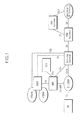
- FIG. 1 is a block diagram showing the configuration of a third generation long term evolution (3G LTE) system.
- 3G LTE third generation long term evolution
- a packet data transmission is performed between a UE and an operator's Internet protocol (IP) service network via a packet data network (PDN) GW, a serving GW, and a base station (evolved Node-B (eNodeB)) of an evolved universal terrestrial radio access network (E-UTRAN).
- IP Internet protocol
- PDN packet data network
- eNodeB evolved Node-B
- E-UTRAN evolved universal terrestrial radio access network
- one eNodeB included in the E-UTRAN can interface with a plurality of MMEs or serving GWs and the relationship thereof may be a 1:N or N: 1 interface.
- an optimal serving GW needs to be selected from among the plurality of serving GWs connected to the eNodeB for the purpose of load distribution or the like.
- the inventor has conducted the research on a technique that can select an optimal network interface entity based on environmental information related to a network interface entity being a traffic transfer path when an MME of a mobile communication system selects a proper network interface entity from among a plurality of network interface entities connecting between a UE and a network.
- the present invention provides a method for selecting a network interface entity in a mobility management entity that can select an optimal network interface entity based on environmental information related to the network interface entity including service requirement of a user equipment, processing capacity of the network interface entity, a location of the user equipment, and a network topology.
- a method for selecting a network interface entity in a mobility management entity including: configuring a group including at least one network interface entity satisfying service requirement for a user equipment and processing capacity requirement for the at least one network interface entity in consideration of the service requirement of the user equipment and processing capacity of the at least one network interface entity; and selecting an optimal network interface entity from the at least one network interface entity belonging to the configured group in consideration of a location of the user equipment and a network topology.
- the present invention may select an optimal network interface entity based on environmental information related to the network interface entity including service requirement of the user equipment, processing capacity of the network interface entity, a location of the user equipment, and a network topology, thereby distributing the load of a mobile communication system and improving the performance thereof.
- FIG. 1 shows the configuration of a 3G LTE system.
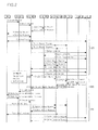
- FIG. 2 shows a UE attach procedure of the 3G LTE system.
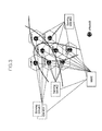
- FIG. 3 shows an example of a connection of an eNodeB and an MME/serving GW of the 3G LTE system.
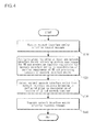
- FIG. 4 is a flowchart showing an example of a network interface entity selection method of the MME according to an embodiment of the present invention.
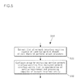
- FIG. 5 is a flowchart showing a grouping procedure of the network interface entity selection method of the MME according to an embodiment of the present invention.
- FIG. 6 shows an example of an eNodeB cell interfacing with a network interface entity.
- FIG. 7 is a flowchart showing an optimal network interface entity selection procedure of the network interface entity selection method of the MME according to an embodiment of the present invention.
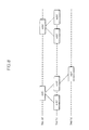
- FIG. 8 shows an example of a neighbor cell tree of a network interface entity.
- a default IP bearer for IP signalling or traffic is established when a UE performs an initial attach procedure.
- an MME selects a serving GW and a PDN GW to interface with a base station (eNodeB) in response to the UE's request, thereby providing the UE with services using the GWs.
- eNodeB base station
- the serving GW allocated at the time of the initial attach procedure of the UE is used until a reset operation is performed through a node relocation procedure of a core network (CN) associated with a handover for the UE.
- CN core network
- FIG. 2 shows a UE attach procedure of the 3G LTE system, which can be divided into an initial attach request process 100 of the UE, a service session (default IP bearer and dedicated IP bearer) establishment process 200, and a process 300 for completing the initial attach procedure of the UE and providing services. Since a detailed processing procedure for attaching the UE departs from the scope of the present invention, a description thereof is omitted.
- a network interface entity selection method of the MME according to an embodiment of the present invention is performed between the initial attach request process 100 of the UE and the service session establishment process 200.
- the MME may be a 3GPP MME, a CDMA2000 BSC, or the like.
- the network interface entity may be a 3GPP serving GW, a CDMA2000 PDSN or the like.
- the 3G LTE system will be described as an example.
- FIG. 3 shows an example of a connection of the eNodeB and the MME/serving GW of the 3G LTE system.
- the eNodeB located in each cell interfaces with the MMB for a control interface and interfaces with the serving GW for a data interface.
- one eNodeB can interface with a plurality of MMEs and a plurality of serving GWs according to a system installation method.
- a specific MME is selected and a serving GW is selected by the selected MME.
- a cell #01 interfaces with a serving GW #01 and a serving GW #04 and a cell #02 interfaces with the serving GW #01 and a serving GW #03.
- the network interface entity selection method of the MME can select an optimal network interface entity based on environmental information related to the network interface entity including service requirement of the UE, processing capacity of the network interface entity, a location of the UE, and a network topology when the MME such as a 3GPP MME or a CDMA2000 BSC selects the network interface entity such as a 3GPP serving GW or CDMA2000 PDSN for a data interface of the eNodeB.
- the network interface entity selection method of the MME uses environmental information as exemplarily shown in Table 1.
- This environmental information can be acquired from an operation, administration, and maintenance (OAM) module defining a criterion and method for providing an OAM function of a communication network.
- OAM operation, administration, and maintenance
- the OAM module can serve as an internal or external function entity of the MME.
- the MME selects a network interface entity in the UE attach process using the environmental information exemplarily shown in Table 1.
- the MME considers two aspects. First, the service requirement of the UE and the processing capacity of the network interface entity should be considered. Second, a minimized network interface entity change should be considered even when the UE to be currently attached moves.
- the MME stores a set of information elements set in Table 1.
- the capacity information is stored as an information amount capable of being processed.
- An example of environmental information shown in FIG. 3 is as follows.
- sgw.n denotes a network interface entity n
- enb.n denotes an eNodeB n .
- FIG. 4 is a flowchart showing an example of the network interface entity selection method of the MME according to an embodiment of the present invention.
- the UE creates an initial attach request in an attach process thereof and the MME receives a network interface entity selection request message including eNodeB identification information from the eNodeB in step S 110.
- the network interface entity selection request message can further include resource information R ue.default required for default IP bearer establishment. This resource information required for the default IP bearer establishment is used when establishing a service session in the attach process of the UE.
- the MME Upon receiving the network interface entity selection request message in step S110, the MME configures a group including at least one network interface entity satisfying service requirement for the UE and processing capacity requirement for the network interface entity in consideration of the service requirement of the UE and processing capacity of the network interface entity in step S120.
- the MME selects an optimal network interface entity from among a plurality of network interface entities included in the group configured in step S120 in consideration of a location of the UE and a network topology in step S130.
- the MME transmits a network interface entity selection response message including identification information of the selected network interface entity to the eNodeB which transmitted the network interface entity selection request message in step S140.
- the optimal network interface entity can be selected on the basis of environmental information related to the network interface entity including the service requirement of the UE, the processing capacity of the network interface entity, the location of the UE, and the network topology, thereby distributing the load of a mobile communication system and improving the performance thereof.
- step S120 the group including at least one network interface entity satisfying the service requirement for the UE and the processing capacity requirement for the network interface entity is configured through the process shown in FIG. 5.
- FIG. 5 is a flowchart showing a grouping procedure of the network interface entity selection method of the MME according to an embodiment of the present invention.
- step S121 the MME extracts a list L sgw.i_enb.n of network interface entities capable of interfacing with an eNodeB of a cell where the UE performs an attach procedure.
- the list L sgw.i_enb.n of network interface entities capable of interfacing with the eNodeB of the cell where the UE performs the attach procedure can be extracted from the environmental information exemplarily shown in Table 1.
- the MME configures the group by extracting service network interface entities from the network interface entity list L sgw.i_enb.n extracted in step S121 in consideration of the service requirement and the processing capacity of the network interface entity in step S122.
- a list of service network interface entities belonging to this group is denoted by L sgw.s .
- the processing capacity of the network interface entity can be computed using a difference between the total processing capacity C sgw of the network interface entity and the allocated bearer capacity R ue.i since the bearer capacity can be detected from bearer allocation information of the currently attached UE.
- C sgw.c the service capacity of the network interface entity (or the processing capacity of the network interface entity)
- band information allocated to the UE i or allocated bearer capacity
- R ue.i the number of attached UEs
- n the number of attached UEs.
- the group can be configured by extracting the service network interface entity list L sgw.s in consideration of an estimated value ⁇ required for dedicated IP bearer establishment to be created later.
- groups are configured by a set of service network interface entity lists L sgw.s satisfying the condition of the following equation.
- the performance of the overall system can be enhanced by selecting a network interface entity having the lowest relocation possibility in consideration of the handover. That is, if the UE has the same mobility probability for cells, the probability of relocation of the network interface entity is lowered when the number of neighbor cells adjacent to the cell in which the attach procedure is performed is large.
- the optimal network interface entity is selected by performing the following detailed operation in step S130.
- FIG. 7 is a flowchart showing an optimal network interface entity selection procedure of the network interface entity selection method of the MME according to an embodiment of the present invention.
- step S131 the MME extracts a neighbor cell list L neighenb.i_enb.n for each network interface entity included in the group configured in step S120.
- the neighbor cell list L neighenb.i_enb.n can be extracted from the environmental information exemplarily shown in Table 1.
- L neighenb.i_enb.1 ⁇ enb.2, enb.3, enb.4 ⁇ .
- the MME extracts a neighbor cell list ⁇ L sgw.i_enb.n for each network interface entity capable of providing the eNodeB service in step S132.
- the neighbor cell list for each network interface entity capable of providing an eNodeB service is cells included in both a list of eNodeBs capable of interfacing with a corresponding network interface entity and a list of cell eNodeBs adjacent to a corresponding cell eNodeB
- step S 133 the MME configures a neighbor cell tree using the neighbor cell list for each network interface entity extracted in step S132.
- the neighbor cell tree is configured by setting a cell eNodeB to which the UE is attached to a root node, setting a neighbor cell eNodeB of the root node to a child node, forming a relation between parent and child nodes, and edge connecting between the parent and child nodes.
- the neighbor cell tree has an n-th depth by repeating an operation for setting an eNodeB of a neighbor cell of the child node to a child node of a corresponding child node, forming a relation between parent and child nodes, and edge connecting between the parent and child nodes.
- the neighbor cell of the child node is a parent node or a sibling node, an edge connection is not made.
- the n-th depth indicates an adjacency relation between a cell eNodeB to which the UE is attached and a neighbor cell. That is, it can be seen that the child node connected to the root node is adjacent to the cell to which the UE is attached and child nodes connected to the child node are adjacent to each other in a state in which one or more cells are present therebetween.
- FIG. 8 shows an example of a neighbor cell tree of a network interface entity.
- step S134 the MME selects a network interface entity having high neighbor cell density from the neighbor cell tree configured in step S 133.
- the neighbor cell density affects the mobility between network interface entities for which the UE can perform the attach procedure, and can be computed using the number of neighbor cells considering the network topology.
- the following equation is an example of an equation for computing the neighbor cell density D sgw.i_enb.n .
- N k is the number of neighbor cells having a k-th depth and an index a is a value of 0 ⁇ a ⁇ 1.
- D sgw . i , enb . n 1 - ⁇ ⁇ N 1 + ⁇ ⁇ 1 - ⁇ ⁇ N 2 + ⁇ 2 ⁇ 1 - ⁇ ⁇ N 3 + ... + ⁇ k ⁇ 1 - ⁇ ⁇ N k + 1
- a network interface entity of the highest neighbor cell density is finally selected to be used for the attach procedure and service of the UE.
- the overall system load can be distributed by selecting an optimal network interface entity on the basis of environmental information related to the network interface entity including service requirement of a UE, processing capacity of the network interface entity, a location of the UE, and a network topology.
- a relocation procedure of the network interface entity can be minimized by selecting the network interface entity associated with a large number of neighbor cells in consideration of the neighbor cell density of a service cell.
- the present invention can be used for technical fields in which an MME of a mobile communication system selects a proper network interface entity and application fields thereof.
Landscapes
- Engineering & Computer Science (AREA)
- Computer Networks & Wireless Communication (AREA)
- Signal Processing (AREA)
- Computer Security & Cryptography (AREA)
- Mobile Radio Communication Systems (AREA)
- Multimedia (AREA)
- Databases & Information Systems (AREA)
- Data Exchanges In Wide-Area Networks (AREA)
Abstract
Description
- This application claims priority from Korean Patent Application No.
10-2007-0127154, filed on December 7, 2007 - The present invention relates to a method for selecting a network interface entity in a mobility management entity (MME), and more particularly, to a technique in which an MME of a mobile communication system selects a proper network interface entity when a user equipment (UE) performs an initial attach process.
- This work was supported by the IT R&D program of Ministry of Information and Communication (MIC)/Institute for Information Technology Advancement (IITA) [2005-S-404-23, Research and development on 3G long-term evolution access system].
- In mobile communication systems, an MME should select a proper network interface entity from among a plurality of network interface entities for connecting between a UE and a network when the UE performs an initial attach process to transmit and receive traffic to and from a packet network.
- The MME may be a 3GPP MME, a CDMA2000 base station controller (BSC), or the like.
- On the other hand, the network interface entity may be a 3GPP serving gateway (GW), a CDMA2000 packet data serving node (PDSN), or the like.
-
FIG. 1 is a block diagram showing the configuration of a third generation long term evolution (3G LTE) system. - In the 3G LTE system, a packet data transmission is performed between a UE and an operator's Internet protocol (IP) service network via a packet data network (PDN) GW, a serving GW, and a base station (evolved Node-B (eNodeB)) of an evolved universal terrestrial radio access network (E-UTRAN).
- Since the 3G LTE system exchanges an IP-based packet, one eNodeB included in the E-UTRAN can interface with a plurality of MMEs or serving GWs and the relationship thereof may be a 1:N or N: 1 interface.
- Accordingly, when a specific UE performs an initial attach process and establishes a service session (default IP bearer and dedicated IP bearer), an optimal serving GW needs to be selected from among the plurality of serving GWs connected to the eNodeB for the purpose of load distribution or the like.
- The inventor has conducted the research on a technique that can select an optimal network interface entity based on environmental information related to a network interface entity being a traffic transfer path when an MME of a mobile communication system selects a proper network interface entity from among a plurality of network interface entities connecting between a UE and a network.
- The present invention provides a method for selecting a network interface entity in a mobility management entity that can select an optimal network interface entity based on environmental information related to the network interface entity including service requirement of a user equipment, processing capacity of the network interface entity, a location of the user equipment, and a network topology.
- According to an aspect of the present invention, there is provided a method for selecting a network interface entity in a mobility management entity, including: configuring a group including at least one network interface entity satisfying service requirement for a user equipment and processing capacity requirement for the at least one network interface entity in consideration of the service requirement of the user equipment and processing capacity of the at least one network interface entity; and selecting an optimal network interface entity from the at least one network interface entity belonging to the configured group in consideration of a location of the user equipment and a network topology.
- The present invention may select an optimal network interface entity based on environmental information related to the network interface entity including service requirement of the user equipment, processing capacity of the network interface entity, a location of the user equipment, and a network topology, thereby distributing the load of a mobile communication system and improving the performance thereof.
- Additional aspects of the invention will be set forth in the description which follows, and in part will be apparent from the description, or may be learned by practice of the invention.
- It is to be understood that both the foregoing general description and the following detailed description are exemplary and explanatory and are intended to provide further explanation of the invention as claimed.
- The accompanying drawings, which are included to provide a further understanding of the invention and are incorporated in and constitute a part of this specification, illustrate exemplary embodiments of the invention, and together with the description serve to explain the aspects of the invention.
-
FIG. 1 shows the configuration of a 3G LTE system. -
FIG. 2 shows a UE attach procedure of the 3G LTE system. -
FIG. 3 shows an example of a connection of an eNodeB and an MME/serving GW of the 3G LTE system. -
FIG. 4 is a flowchart showing an example of a network interface entity selection method of the MME according to an embodiment of the present invention. -
FIG. 5 is a flowchart showing a grouping procedure of the network interface entity selection method of the MME according to an embodiment of the present invention. -
FIG. 6 shows an example of an eNodeB cell interfacing with a network interface entity. -
FIG. 7 is a flowchart showing an optimal network interface entity selection procedure of the network interface entity selection method of the MME according to an embodiment of the present invention. -
FIG. 8 shows an example of a neighbor cell tree of a network interface entity. - The invention is described more fully hereinafter with reference to the accompanying drawings, in which exemplary embodiments of the invention are shown. This invention may, however, be embodied in many different forms and should not be construed as limited to the exemplary embodiments set forth herein. Rather, these exemplary embodiments are provided so that this disclosure is thorough, and will fully convey the scope of the invention to those skilled in the art.
- In a case of a 3G LTE system, a default IP bearer for IP signalling or traffic is established when a UE performs an initial attach procedure. At this time, an MME selects a serving GW and a PDN GW to interface with a base station (eNodeB) in response to the UE's request, thereby providing the UE with services using the GWs.
- The serving GW allocated at the time of the initial attach procedure of the UE is used until a reset operation is performed through a node relocation procedure of a core network (CN) associated with a handover for the UE.
-
FIG. 2 shows a UE attach procedure of the 3G LTE system, which can be divided into an initialattach request process 100 of the UE, a service session (default IP bearer and dedicated IP bearer)establishment process 200, and aprocess 300 for completing the initial attach procedure of the UE and providing services. Since a detailed processing procedure for attaching the UE departs from the scope of the present invention, a description thereof is omitted. - A network interface entity selection method of the MME according to an embodiment of the present invention is performed between the initial
attach request process 100 of the UE and the servicesession establishment process 200. - At this time, the MME may be a 3GPP MME, a CDMA2000 BSC, or the like. On the other hand, the network interface entity may be a 3GPP serving GW, a CDMA2000 PDSN or the like. In the present invention, for convenience, the 3G LTE system will be described as an example.
-
FIG. 3 shows an example of a connection of the eNodeB and the MME/serving GW of the 3G LTE system. The eNodeB located in each cell interfaces with the MMB for a control interface and interfaces with the serving GW for a data interface. - As shown in
FIG. 3 , one eNodeB can interface with a plurality of MMEs and a plurality of serving GWs according to a system installation method. When an attach procedure for a specific service is performed, a specific MME is selected and a serving GW is selected by the selected MME. - In
FIG. 3 , it can be seen that acell # 01 interfaces with a servingGW # 01 and a servingGW # 04 and acell # 02 interfaces with the servingGW # 01 and a servingGW # 03. - The network interface entity selection method of the MME according to the embodiment of the present invention can select an optimal network interface entity based on environmental information related to the network interface entity including service requirement of the UE, processing capacity of the network interface entity, a location of the UE, and a network topology when the MME such as a 3GPP MME or a CDMA2000 BSC selects the network interface entity such as a 3GPP serving GW or CDMA2000 PDSN for a data interface of the eNodeB.
- For this, the network interface entity selection method of the MME according to the embodiment of the present invention uses environmental information as exemplarily shown in Table 1. This environmental information can be acquired from an operation, administration, and maintenance (OAM) module defining a criterion and method for providing an OAM function of a communication network. The OAM module can serve as an internal or external function entity of the MME.
- According to the network interface entity selection method of the MME according to the embodiment of the present invention, the MME selects a network interface entity in the UE attach process using the environmental information exemplarily shown in Table 1. At this time, the MME considers two aspects. First, the service requirement of the UE and the processing capacity of the network interface entity should be considered. Second, a minimized network interface entity change should be considered even when the UE to be currently attached moves.
TABLE 1 Setting Information Description Network interface entity list Lsgw List of network interface entities to be controlled by MME List Lsgw.i_enb.n of network interface entities capable of interfacing with eNodeB List of network interface entities capable of interfacing with eNodeB n List Lsgw.i_enb.n of eNodeBs capable of interfacing with network interface entity List of eNodeBs capable of interfacing with network interface entity Neighbor eNodeB list Lneighenb.i_enb.n List of neighbor cell eNodeBs adjacent to eNodeB n Processing capacity Csgw.i of network interface entity Total service capacity of network interface entity i - The MME stores a set of information elements set in Table 1. The capacity information is stored as an information amount capable of being processed. An example of environmental information shown in
FIG. 3 is as follows. Here, sgw.n denotes a network interface entity n and enb.n denotes an eNodeB n.
Network interface entity list: - Lsgw = {sgw.1, sgw.2, sgw.3, sgw.4}
- Lsgw.i_enb.n = {sgw.1, sgw.4}
- Lenb.i_sgw.1 = {end.1, enb.2, enb.3, enb.4}
- Lneighenb.i_enb.3 = {enb.1, enb.2, enb.4, enb.5, enb.6}
- Csgw.1 = c
-
FIG. 4 is a flowchart showing an example of the network interface entity selection method of the MME according to an embodiment of the present invention. - In the network interface entity selection method of the MME according to the embodiment of the present invention as shown in
FIG. 4 , the UE creates an initial attach request in an attach process thereof and the MME receives a network interface entity selection request message including eNodeB identification information from the eNodeB in step S 110. - At this time, the network interface entity selection request message can further include resource information Rue.default required for default IP bearer establishment. This resource information required for the default IP bearer establishment is used when establishing a service session in the attach process of the UE.
- Upon receiving the network interface entity selection request message in step S110, the MME configures a group including at least one network interface entity satisfying service requirement for the UE and processing capacity requirement for the network interface entity in consideration of the service requirement of the UE and processing capacity of the network interface entity in step S120.
- Then, the MME selects an optimal network interface entity from among a plurality of network interface entities included in the group configured in step S120 in consideration of a location of the UE and a network topology in step S130.
- When the network interface entity selection is completed in
step S 130, the MME transmits a network interface entity selection response message including identification information of the selected network interface entity to the eNodeB which transmitted the network interface entity selection request message in step S140. - According to the embodiment of the present invention, the optimal network interface entity can be selected on the basis of environmental information related to the network interface entity including the service requirement of the UE, the processing capacity of the network interface entity, the location of the UE, and the network topology, thereby distributing the load of a mobile communication system and improving the performance thereof.
- Specifically, in step S120, the group including at least one network interface entity satisfying the service requirement for the UE and the processing capacity requirement for the network interface entity is configured through the process shown in
FIG. 5. FIG. 5 is a flowchart showing a grouping procedure of the network interface entity selection method of the MME according to an embodiment of the present invention. - First, in step S121, the MME extracts a list Lsgw.i_enb.n of network interface entities capable of interfacing with an eNodeB of a cell where the UE performs an attach procedure. At this time, the list Lsgw.i_enb.n of network interface entities capable of interfacing with the eNodeB of the cell where the UE performs the attach procedure can be extracted from the environmental information exemplarily shown in Table 1.
- When there is no interface entity, the attach procedure of the UE is rejected. When there is at least one interface entity, the MME configures the group by extracting service network interface entities from the network interface entity list Lsgw.i_enb.n extracted in step S121 in consideration of the service requirement and the processing capacity of the network interface entity in step S122. A list of service network interface entities belonging to this group is denoted by Lsgw.s.
- At this time, in step S122, the processing capacity of the network interface entity can be computed using a difference between the total processing capacity Csgw of the network interface entity and the allocated bearer capacity Rue.i since the bearer capacity can be detected from bearer allocation information of the currently attached UE. This is defined by the following equation. When the UE creates the attach request, the service capacity of the network interface entity (or the processing capacity of the network interface entity) is denoted by Csgw.c, band information allocated to the UE i (or allocated bearer capacity) is denoted by Rue.i, and the number of attached UEs is denoted by n.
- On the other hand, since only quality of service (QoS) information for default IP bearer establishment is provided when the UE performs the initial attach procedure, the group can be configured by extracting the service network interface entity list Lsgw.s in consideration of an estimated value λ required for dedicated IP bearer establishment to be created later.
- That is, groups are configured by a set of service network interface entity lists Lsgw.s satisfying the condition of the following equation.

- Since the UE has mobility, the performance of the overall system can be enhanced by selecting a network interface entity having the lowest relocation possibility in consideration of the handover. That is, if the UE has the same mobility probability for cells, the probability of relocation of the network interface entity is lowered when the number of neighbor cells adjacent to the cell in which the attach procedure is performed is large.
- To satisfy this condition, the optimal network interface entity is selected by performing the following detailed operation in step S130.
- It is assumed that the group of members of network interface entities satisfying the service requirement of the UE and the processing capacity of the network interface entity in step S120 is Lsgw.s = {sgw.1, sgw.2} and regions of the network interwork entities sgw.1 and sgw.2 are the same as shown in
FIG. 6 . -
FIG. 7 is a flowchart showing an optimal network interface entity selection procedure of the network interface entity selection method of the MME according to an embodiment of the present invention. - In step S131, the MME extracts a neighbor cell list Lneighenb.i_enb.n for each network interface entity included in the group configured in step S120. At this time, the neighbor cell list Lneighenb.i_enb.n can be extracted from the environmental information exemplarily shown in Table 1. For example, referring to
FIG. 6 , Lneighenb.i_enb.1 = {enb.2, enb.3, enb.4}. - Then, the MME extracts a neighbor cell list µLsgw.i_enb.n for each network interface entity capable of providing the eNodeB service in step S132. At this time, since the neighbor cell list for each network interface entity capable of providing an eNodeB service is cells included in both a list of eNodeBs capable of interfacing with a corresponding network interface entity and a list of cell eNodeBs adjacent to a corresponding cell eNodeB, the neighbor cell lists can be extracted from the following equation.

- For example, referring to
FIG. 6 , µLsgw.2_enb.1 = {enb.2, enb.4} and µLsgw.1_enb.1 = {enb.2, enb.4, enb.5}. - Then, in
step S 133, the MME configures a neighbor cell tree using the neighbor cell list for each network interface entity extracted in step S132. - At this time, the neighbor cell tree is configured by setting a cell eNodeB to which the UE is attached to a root node, setting a neighbor cell eNodeB of the root node to a child node, forming a relation between parent and child nodes, and edge connecting between the parent and child nodes.
- Moreover, the neighbor cell tree has an n-th depth by repeating an operation for setting an eNodeB of a neighbor cell of the child node to a child node of a corresponding child node, forming a relation between parent and child nodes, and edge connecting between the parent and child nodes. On the other hand, when the neighbor cell of the child node is a parent node or a sibling node, an edge connection is not made.
- The n-th depth indicates an adjacency relation between a cell eNodeB to which the UE is attached and a neighbor cell. That is, it can be seen that the child node connected to the root node is adjacent to the cell to which the UE is attached and child nodes connected to the child node are adjacent to each other in a state in which one or more cells are present therebetween.
- Accordingly, the density of neighbor cells of a cell eNodeB to perform the attach process can be detected from n-th depth information.
FIG. 8 shows an example of a neighbor cell tree of a network interface entity. - In step S134, the MME selects a network interface entity having high neighbor cell density from the neighbor cell tree configured in
step S 133. - The neighbor cell density affects the mobility between network interface entities for which the UE can perform the attach procedure, and can be computed using the number of neighbor cells considering the network topology. The following equation is an example of an equation for computing the neighbor cell density Dsgw.i_enb.n. In the equation, Nk is the number of neighbor cells having a k-th depth and an index a is a value of 0 < a < 1.

- Since the probability of occurrence of a relocation procedure of a network interface entity having high neighbor cell density is low even when the UE moves, a network interface entity of the highest neighbor cell density is finally selected to be used for the attach procedure and service of the UE.
- According to the embodiment of the present invention, when a large number of network interface entities interface with the MME of the mobile communication system, the overall system load can be distributed by selecting an optimal network interface entity on the basis of environmental information related to the network interface entity including service requirement of a UE, processing capacity of the network interface entity, a location of the UE, and a network topology. A relocation procedure of the network interface entity can be minimized by selecting the network interface entity associated with a large number of neighbor cells in consideration of the neighbor cell density of a service cell.
- As apparent from the above description, the present invention can be used for technical fields in which an MME of a mobile communication system selects a proper network interface entity and application fields thereof.
- It will be apparent to those skilled in the art that various modifications and variations can be made in the present invention without departing from the spirit or scope of the invention. Thus, it is intended that the present invention covers the modifications and variations of this invention provided they come within the scope of the appended claims and their equivalents.
Claims (12)
- A method for selecting a network interface entity in a mobility management entity, comprising:configuring a group including at least one network interface entity satisfying service requirement for a user equipment and processing capacity requirement for the at least one network interface entity in consideration of the service requirement of the user equipment and processing capacity of the at least one network interface entity; andselecting an optimal network interface entity from the at least one network interface entity belonging to the configured group in consideration of a location of the user equipment and a network topology.
- The method of claim 1, wherein the configuring of the group comprises:extracting a list of network interface entities capable of interfacing with an eNodeB of a cell where the user equipment performs an attach procedure; andconfiguring the group by extracting network interface entities capable of providing a service from the extracted network interface entity list in consideration of the service requirement of the user equipment and the processing capacity of the at least one network interface entity.
- The method of claim 1, wherein the selecting of the optimal network interface entity comprises:extracting a neighbor cell list for each network interface entity belonging to the configured group;extracting a neighbor cell list for each network interface entity capable of providing an eNodeB service;configuring a neighbor cell tree using the extracted neighbor cell list for each network interface entity; andselecting a network interface entity having high neighbor cell density from the configured neighbor cell tree.
- The method of claim 2, wherein the processing capacity of the at least one network interface entity is computed using a difference between total processing capacity of the at least one network interface entity and preset bearer capacity.
- The method of claim 4, wherein the processing capacity of the at least one network interface entity is computed by further reflecting an estimated value required for dedicated IP bearer establishment to be created later.
- The method of claim 3, wherein the extracted neighbor cell list for each network interface entity capable of providing the eNodeB service comprises cells included in both a list of eNodeBs capable of interfacing with a corresponding network interface entity and a list of cell eNodeBs neighboring to a corresponding cell eNodeB.
- The method of claim 3, wherein the neighbor cell tree is configured by setting a cell eNodeB to which the user equipment is attached to a root node, setting a neighbor cell eNodeB of the root node to a child node, forming a relation between parent and child nodes, and edge connecting between the parent and child nodes.
- The method of claim 7, wherein the neighbor cell tree is configured by further setting an eNodeB of a neighbor cell of the child node to a child node of a corresponding child node, forming a relation between parent and child nodes, and edge connecting between the parent and child nodes.
- The method of claim 8, wherein when the neighbor cell of the child node is a parent node or a sibling node, an edge connection is not made.
- The method of claims 1, further comprising:receiving a network interface entity selection request message including eNodeB identification information from an eNodeB in an attach process of the user equipment.
- The method of claim 10, further comprising:transmitting a network interface entity selection response message including selected network interface entity identification information to the eNodeB which transmitted the network interface entity selection request message when network interface entity selection is completed.
- The method of claim 10, wherein the network interface entity selection request message further comprises resource information required for default IP bearer establishment.
Applications Claiming Priority (1)
| Application Number | Priority Date | Filing Date | Title |
|---|---|---|---|
| KR1020070127154A KR100966181B1 (en) | 2007-12-07 | 2007-12-07 | How to select network interworking object of mobility management object |
Publications (3)
| Publication Number | Publication Date |
|---|---|
| EP2068593A2 true EP2068593A2 (en) | 2009-06-10 |
| EP2068593A3 EP2068593A3 (en) | 2013-02-20 |
| EP2068593B1 EP2068593B1 (en) | 2014-05-07 |
Family
ID=40459705
Family Applications (1)
| Application Number | Title | Priority Date | Filing Date |
|---|---|---|---|
| EP20080159496 Active EP2068593B1 (en) | 2007-12-07 | 2008-07-02 | Method for selecting network interface entity in mobility management entity |
Country Status (2)
| Country | Link |
|---|---|
| EP (1) | EP2068593B1 (en) |
| KR (1) | KR100966181B1 (en) |
Family Cites Families (6)
| Publication number | Priority date | Publication date | Assignee | Title |
|---|---|---|---|---|
| US7043253B2 (en) | 2001-12-26 | 2006-05-09 | Telefonaktiebolaget Lm Ericsson (Publ) | Load balancing in a mobile telecommunications network |
| EP1526752B1 (en) * | 2002-02-06 | 2011-11-09 | Ntt Docomo, Inc. | Using subnet relations for authentication, association and to activate network interfaces in heterogeneous access networks |
| KR100703264B1 (en) * | 2003-08-29 | 2007-04-03 | 삼성전자주식회사 | Method and apparatus for providing voice and data service in mobile communication system with various access networks |
| US20050143087A1 (en) | 2003-12-29 | 2005-06-30 | Telefonaktiebolaget L M Ericsson (Publ) | Dynamic selection of a packet data serving node |
| EP1878285B1 (en) | 2005-04-26 | 2011-08-10 | Vodafone Group PLC | Fast user plane establishment in a telecommunications network |
| US7835743B2 (en) * | 2005-08-03 | 2010-11-16 | Toshiba America Research, Inc. | Seamless network interface selection, handoff and management in multi-IP network interface mobile devices |
-
2007
- 2007-12-07 KR KR1020070127154A patent/KR100966181B1/en active Active
-
2008
- 2008-07-02 EP EP20080159496 patent/EP2068593B1/en active Active
Non-Patent Citations (1)
| Title |
|---|
| None |
Also Published As
| Publication number | Publication date |
|---|---|
| KR20090060024A (en) | 2009-06-11 |
| KR100966181B1 (en) | 2010-06-25 |
| EP2068593A3 (en) | 2013-02-20 |
| EP2068593B1 (en) | 2014-05-07 |
Similar Documents
| Publication | Publication Date | Title |
|---|---|---|
| US11864047B2 (en) | Methods and base stations for reporting results of load measurements | |
| CN102349325B (en) | Load sharing method, device and system thereof | |
| US8724590B2 (en) | System and method for primary point handovers | |
| EP3338485B1 (en) | User equipment, base station and associated methods | |
| US8320311B2 (en) | Method and system for establishing high-speed downlink shared channel | |
| US20150141062A1 (en) | Method and Node for Paging in a Radio Access Network | |
| CN108418609A (en) | The system and method that radio bearer management is carried out to multicast communication | |
| US10320449B2 (en) | Dynamic cell clustering for coordinated multipoint operation | |
| US20110199937A1 (en) | Method for configuring a wireless network | |
| CN101861753A (en) | Radio network controller, mobile communication system and method for avoiding call connection completion deterioration | |
| KR101238993B1 (en) | Traffic transmission path relocation method for radio communication system | |
| EP3372050A1 (en) | Interface setup between cellular communication system and wlan | |
| WO2010075717A1 (en) | Method and device for users' uplink and downlink unsynchronized switching | |
| US9549423B2 (en) | Method and device for increasing gateway capacity in LTE mode Femto cell system | |
| CN102111812B (en) | Method, equipment and system for allocating balanced access resources | |
| US20130109381A1 (en) | Mobile communication system, radio access network apparatus, and mobile station | |
| EP2068593B1 (en) | Method for selecting network interface entity in mobility management entity | |
| KR20160126830A (en) | Base station and bearer split method by the same | |
| EP4021072A1 (en) | Data processing method, apparatus, and system | |
| EP4440197B1 (en) | Apparatuses, methods, and computer programs for conditional mobility | |
| CN101547439A (en) | A restart method between network elements in a communication system |
Legal Events
| Date | Code | Title | Description |
|---|---|---|---|
| PUAI | Public reference made under article 153(3) epc to a published international application that has entered the european phase |
Free format text: ORIGINAL CODE: 0009012 |
|
| AK | Designated contracting states |
Kind code of ref document: A2 Designated state(s): AT BE BG CH CY CZ DE DK EE ES FI FR GB GR HR HU IE IS IT LI LT LU LV MC MT NL NO PL PT RO SE SI SK TR |
|
| AX | Request for extension of the european patent |
Extension state: AL BA MK RS |
|
| RAP1 | Party data changed (applicant data changed or rights of an application transferred) |
Owner name: SAMSUNG ELECTRONICS CO., LTD. Owner name: ELECTRONICS AND TELECOMMUNICATIONS RESEARCH INSTIT |
|
| PUAL | Search report despatched |
Free format text: ORIGINAL CODE: 0009013 |
|
| AK | Designated contracting states |
Kind code of ref document: A3 Designated state(s): AT BE BG CH CY CZ DE DK EE ES FI FR GB GR HR HU IE IS IT LI LT LU LV MC MT NL NO PL PT RO SE SI SK TR |
|
| AX | Request for extension of the european patent |
Extension state: AL BA MK RS |
|
| RIC1 | Information provided on ipc code assigned before grant |
Ipc: H04W 48/18 20090101AFI20130114BHEP |
|
| 17P | Request for examination filed |
Effective date: 20130820 |
|
| RBV | Designated contracting states (corrected) |
Designated state(s): AT BE BG CH CY CZ DE DK EE ES FI FR GB GR HR HU IE IS IT LI LT LU LV MC MT NL NO PL PT RO SE SI SK TR |
|
| AKX | Designation fees paid |
Designated state(s): AT BE BG CH CY CZ DE DK EE ES FI FR GB GR HR HU IE IS IT LI LT LU LV MC MT NL NO PL PT RO SE SI SK TR |
|
| RIN1 | Information on inventor provided before grant (corrected) |
Inventor name: SHIN, YEON-SEUNG Inventor name: KIM, WON-IK Inventor name: SONG, JAE-SU Inventor name: BAEK, SEUNG-KWON Inventor name: KIM, YEONG-JIN |
|
| RAP1 | Party data changed (applicant data changed or rights of an application transferred) |
Owner name: SAMSUNG ELECTRONICS CO., LTD. Owner name: ELECTRONICS AND TELECOMMUNICATIONS RESEARCH INSTIT |
|
| GRAP | Despatch of communication of intention to grant a patent |
Free format text: ORIGINAL CODE: EPIDOSNIGR1 |
|
| INTG | Intention to grant announced |
Effective date: 20131220 |
|
| GRAS | Grant fee paid |
Free format text: ORIGINAL CODE: EPIDOSNIGR3 |
|
| GRAA | (expected) grant |
Free format text: ORIGINAL CODE: 0009210 |
|
| AK | Designated contracting states |
Kind code of ref document: B1 Designated state(s): AT BE BG CH CY CZ DE DK EE ES FI FR GB GR HR HU IE IS IT LI LT LU LV MC MT NL NO PL PT RO SE SI SK TR |
|
| REG | Reference to a national code |
Ref country code: GB Ref legal event code: FG4D |
|
| REG | Reference to a national code |
Ref country code: AT Ref legal event code: REF Ref document number: 667485 Country of ref document: AT Kind code of ref document: T Effective date: 20140515 |
|
| REG | Reference to a national code |
Ref country code: IE Ref legal event code: FG4D |
|
| REG | Reference to a national code |
Ref country code: DE Ref legal event code: R096 Ref document number: 602008031998 Country of ref document: DE Effective date: 20140618 |
|
| REG | Reference to a national code |
Ref country code: AT Ref legal event code: MK05 Ref document number: 667485 Country of ref document: AT Kind code of ref document: T Effective date: 20140507 |
|
| REG | Reference to a national code |
Ref country code: NL Ref legal event code: VDEP Effective date: 20140507 |
|
| REG | Reference to a national code |
Ref country code: LT Ref legal event code: MG4D |
|
| PG25 | Lapsed in a contracting state [announced via postgrant information from national office to epo] |
Ref country code: GR Free format text: LAPSE BECAUSE OF FAILURE TO SUBMIT A TRANSLATION OF THE DESCRIPTION OR TO PAY THE FEE WITHIN THE PRESCRIBED TIME-LIMIT Effective date: 20140808 Ref country code: LT Free format text: LAPSE BECAUSE OF FAILURE TO SUBMIT A TRANSLATION OF THE DESCRIPTION OR TO PAY THE FEE WITHIN THE PRESCRIBED TIME-LIMIT Effective date: 20140507 Ref country code: NO Free format text: LAPSE BECAUSE OF FAILURE TO SUBMIT A TRANSLATION OF THE DESCRIPTION OR TO PAY THE FEE WITHIN THE PRESCRIBED TIME-LIMIT Effective date: 20140807 Ref country code: IS Free format text: LAPSE BECAUSE OF FAILURE TO SUBMIT A TRANSLATION OF THE DESCRIPTION OR TO PAY THE FEE WITHIN THE PRESCRIBED TIME-LIMIT Effective date: 20140907 Ref country code: CY Free format text: LAPSE BECAUSE OF FAILURE TO SUBMIT A TRANSLATION OF THE DESCRIPTION OR TO PAY THE FEE WITHIN THE PRESCRIBED TIME-LIMIT Effective date: 20140507 Ref country code: FI Free format text: LAPSE BECAUSE OF FAILURE TO SUBMIT A TRANSLATION OF THE DESCRIPTION OR TO PAY THE FEE WITHIN THE PRESCRIBED TIME-LIMIT Effective date: 20140507 |
|
| PG25 | Lapsed in a contracting state [announced via postgrant information from national office to epo] |
Ref country code: AT Free format text: LAPSE BECAUSE OF FAILURE TO SUBMIT A TRANSLATION OF THE DESCRIPTION OR TO PAY THE FEE WITHIN THE PRESCRIBED TIME-LIMIT Effective date: 20140507 Ref country code: LV Free format text: LAPSE BECAUSE OF FAILURE TO SUBMIT A TRANSLATION OF THE DESCRIPTION OR TO PAY THE FEE WITHIN THE PRESCRIBED TIME-LIMIT Effective date: 20140507 Ref country code: PL Free format text: LAPSE BECAUSE OF FAILURE TO SUBMIT A TRANSLATION OF THE DESCRIPTION OR TO PAY THE FEE WITHIN THE PRESCRIBED TIME-LIMIT Effective date: 20140507 Ref country code: HR Free format text: LAPSE BECAUSE OF FAILURE TO SUBMIT A TRANSLATION OF THE DESCRIPTION OR TO PAY THE FEE WITHIN THE PRESCRIBED TIME-LIMIT Effective date: 20140507 Ref country code: ES Free format text: LAPSE BECAUSE OF FAILURE TO SUBMIT A TRANSLATION OF THE DESCRIPTION OR TO PAY THE FEE WITHIN THE PRESCRIBED TIME-LIMIT Effective date: 20140507 Ref country code: SE Free format text: LAPSE BECAUSE OF FAILURE TO SUBMIT A TRANSLATION OF THE DESCRIPTION OR TO PAY THE FEE WITHIN THE PRESCRIBED TIME-LIMIT Effective date: 20140507 |
|
| PG25 | Lapsed in a contracting state [announced via postgrant information from national office to epo] |
Ref country code: PT Free format text: LAPSE BECAUSE OF FAILURE TO SUBMIT A TRANSLATION OF THE DESCRIPTION OR TO PAY THE FEE WITHIN THE PRESCRIBED TIME-LIMIT Effective date: 20140908 |
|
| PG25 | Lapsed in a contracting state [announced via postgrant information from national office to epo] |
Ref country code: SK Free format text: LAPSE BECAUSE OF FAILURE TO SUBMIT A TRANSLATION OF THE DESCRIPTION OR TO PAY THE FEE WITHIN THE PRESCRIBED TIME-LIMIT Effective date: 20140507 Ref country code: RO Free format text: LAPSE BECAUSE OF FAILURE TO SUBMIT A TRANSLATION OF THE DESCRIPTION OR TO PAY THE FEE WITHIN THE PRESCRIBED TIME-LIMIT Effective date: 20140507 Ref country code: DK Free format text: LAPSE BECAUSE OF FAILURE TO SUBMIT A TRANSLATION OF THE DESCRIPTION OR TO PAY THE FEE WITHIN THE PRESCRIBED TIME-LIMIT Effective date: 20140507 Ref country code: CZ Free format text: LAPSE BECAUSE OF FAILURE TO SUBMIT A TRANSLATION OF THE DESCRIPTION OR TO PAY THE FEE WITHIN THE PRESCRIBED TIME-LIMIT Effective date: 20140507 Ref country code: BE Free format text: LAPSE BECAUSE OF FAILURE TO SUBMIT A TRANSLATION OF THE DESCRIPTION OR TO PAY THE FEE WITHIN THE PRESCRIBED TIME-LIMIT Effective date: 20140507 Ref country code: EE Free format text: LAPSE BECAUSE OF FAILURE TO SUBMIT A TRANSLATION OF THE DESCRIPTION OR TO PAY THE FEE WITHIN THE PRESCRIBED TIME-LIMIT Effective date: 20140507 |
|
| REG | Reference to a national code |
Ref country code: DE Ref legal event code: R097 Ref document number: 602008031998 Country of ref document: DE |
|
| PG25 | Lapsed in a contracting state [announced via postgrant information from national office to epo] |
Ref country code: NL Free format text: LAPSE BECAUSE OF FAILURE TO SUBMIT A TRANSLATION OF THE DESCRIPTION OR TO PAY THE FEE WITHIN THE PRESCRIBED TIME-LIMIT Effective date: 20140507 Ref country code: LU Free format text: LAPSE BECAUSE OF FAILURE TO SUBMIT A TRANSLATION OF THE DESCRIPTION OR TO PAY THE FEE WITHIN THE PRESCRIBED TIME-LIMIT Effective date: 20140702 |
|
| REG | Reference to a national code |
Ref country code: CH Ref legal event code: PL |
|
| PLBE | No opposition filed within time limit |
Free format text: ORIGINAL CODE: 0009261 |
|
| STAA | Information on the status of an ep patent application or granted ep patent |
Free format text: STATUS: NO OPPOSITION FILED WITHIN TIME LIMIT |
|
| 26N | No opposition filed |
Effective date: 20150210 |
|
| REG | Reference to a national code |
Ref country code: IE Ref legal event code: MM4A |
|
| REG | Reference to a national code |
Ref country code: FR Ref legal event code: ST Effective date: 20150331 |
|
| GBPC | Gb: european patent ceased through non-payment of renewal fee |
Effective date: 20140807 |
|
| PG25 | Lapsed in a contracting state [announced via postgrant information from national office to epo] |
Ref country code: IT Free format text: LAPSE BECAUSE OF FAILURE TO SUBMIT A TRANSLATION OF THE DESCRIPTION OR TO PAY THE FEE WITHIN THE PRESCRIBED TIME-LIMIT Effective date: 20140507 Ref country code: LI Free format text: LAPSE BECAUSE OF NON-PAYMENT OF DUE FEES Effective date: 20140731 Ref country code: CH Free format text: LAPSE BECAUSE OF NON-PAYMENT OF DUE FEES Effective date: 20140731 |
|
| REG | Reference to a national code |
Ref country code: DE Ref legal event code: R097 Ref document number: 602008031998 Country of ref document: DE Effective date: 20150210 |
|
| PG25 | Lapsed in a contracting state [announced via postgrant information from national office to epo] |
Ref country code: FR Free format text: LAPSE BECAUSE OF NON-PAYMENT OF DUE FEES Effective date: 20140731 |
|
| PG25 | Lapsed in a contracting state [announced via postgrant information from national office to epo] |
Ref country code: GB Free format text: LAPSE BECAUSE OF NON-PAYMENT OF DUE FEES Effective date: 20140807 Ref country code: SI Free format text: LAPSE BECAUSE OF FAILURE TO SUBMIT A TRANSLATION OF THE DESCRIPTION OR TO PAY THE FEE WITHIN THE PRESCRIBED TIME-LIMIT Effective date: 20140507 |
|
| PG25 | Lapsed in a contracting state [announced via postgrant information from national office to epo] |
Ref country code: IE Free format text: LAPSE BECAUSE OF NON-PAYMENT OF DUE FEES Effective date: 20140702 |
|
| PG25 | Lapsed in a contracting state [announced via postgrant information from national office to epo] |
Ref country code: MC Free format text: LAPSE BECAUSE OF FAILURE TO SUBMIT A TRANSLATION OF THE DESCRIPTION OR TO PAY THE FEE WITHIN THE PRESCRIBED TIME-LIMIT Effective date: 20140507 |
|
| PG25 | Lapsed in a contracting state [announced via postgrant information from national office to epo] |
Ref country code: BG Free format text: LAPSE BECAUSE OF FAILURE TO SUBMIT A TRANSLATION OF THE DESCRIPTION OR TO PAY THE FEE WITHIN THE PRESCRIBED TIME-LIMIT Effective date: 20140507 |
|
| PG25 | Lapsed in a contracting state [announced via postgrant information from national office to epo] |
Ref country code: MT Free format text: LAPSE BECAUSE OF FAILURE TO SUBMIT A TRANSLATION OF THE DESCRIPTION OR TO PAY THE FEE WITHIN THE PRESCRIBED TIME-LIMIT Effective date: 20140507 |
|
| PG25 | Lapsed in a contracting state [announced via postgrant information from national office to epo] |
Ref country code: TR Free format text: LAPSE BECAUSE OF FAILURE TO SUBMIT A TRANSLATION OF THE DESCRIPTION OR TO PAY THE FEE WITHIN THE PRESCRIBED TIME-LIMIT Effective date: 20140507 Ref country code: HU Free format text: LAPSE BECAUSE OF FAILURE TO SUBMIT A TRANSLATION OF THE DESCRIPTION OR TO PAY THE FEE WITHIN THE PRESCRIBED TIME-LIMIT; INVALID AB INITIO Effective date: 20080702 |
|
| PGFP | Annual fee paid to national office [announced via postgrant information from national office to epo] |
Ref country code: DE Payment date: 20250624 Year of fee payment: 18 |