EP2068346A2 - Orthogonal acceleration time-of-flight mas spectrometer - Google Patents
Orthogonal acceleration time-of-flight mas spectrometer Download PDFInfo
- Publication number
- EP2068346A2 EP2068346A2 EP08253697A EP08253697A EP2068346A2 EP 2068346 A2 EP2068346 A2 EP 2068346A2 EP 08253697 A EP08253697 A EP 08253697A EP 08253697 A EP08253697 A EP 08253697A EP 2068346 A2 EP2068346 A2 EP 2068346A2
- Authority
- EP
- European Patent Office
- Prior art keywords
- ion
- ions
- potential
- conductive box
- mass spectrometer
- Prior art date
- Legal status (The legal status is an assumption and is not a legal conclusion. Google has not performed a legal analysis and makes no representation as to the accuracy of the status listed.)
- Granted
Links
Images



Classifications
-
- H—ELECTRICITY
- H01—ELECTRIC ELEMENTS
- H01J—ELECTRIC DISCHARGE TUBES OR DISCHARGE LAMPS
- H01J49/00—Particle spectrometers or separator tubes
- H01J49/26—Mass spectrometers or separator tubes
- H01J49/34—Dynamic spectrometers
- H01J49/40—Time-of-flight spectrometers
- H01J49/401—Time-of-flight spectrometers characterised by orthogonal acceleration, e.g. focusing or selecting the ions, pusher electrode
-
- H—ELECTRICITY
- H01—ELECTRIC ELEMENTS
- H01J—ELECTRIC DISCHARGE TUBES OR DISCHARGE LAMPS
- H01J49/00—Particle spectrometers or separator tubes
- H01J49/0027—Methods for using particle spectrometers
- H01J49/0031—Step by step routines describing the use of the apparatus
-
- H—ELECTRICITY
- H01—ELECTRIC ELEMENTS
- H01J—ELECTRIC DISCHARGE TUBES OR DISCHARGE LAMPS
- H01J49/00—Particle spectrometers or separator tubes
- H01J49/02—Details
- H01J49/022—Circuit arrangements, e.g. for generating deviation currents or voltages ; Components associated with high voltage supply
Definitions
- the present invention relates to an orthogonal acceleration time-of-flight mass spectrometer for use in quantitative analysis of trace compounds, qualitative simultaneous analysis of trace compounds, and structural analysis of sample ions.
- TOFMS Time-of-flight mass spectrometer
- a time-of-flight mass spectrometer is an apparatus for finding the mass-to-charge ratios of ions from the times taken for the ions to reach a detector after a given amount of energy is given to the ions such that they accelerate and fly.
- ions are accelerated by a constant pulsed voltage V a .
- TOFMS is an apparatus that isolates masses utilizing this fact.
- a pulse ion source 10 including a pulse voltage generator 12 is a source of ions 14 which travel to detector 16 according to arrow 18, with ions of smaller mass arriving at the detector first.
- reflectron TOFMS has enjoyed wide acceptance because the apparatus permits improvement of energy convergence and increase in flight distance by placing a reflectron field between an ion source and a detector.
- Fig. 2 One example of reflectron TOFMS is shown in Fig. 2 .
- the reflectron, TOMS also includes a pulse ion source 10 having a pulse voltage generator 12.
- the ions 14 travel to detector 16 according to arrow 20, which indicates the curved path of the ions 14 within reflector 22. Again, ions of smaller mass arrive at the detector first.
- TOFMS must accelerate ions in a pulsed manner by the ion accelerating region in order to analyze variations in mass-to-charge ratio as the elapsed times from a starting point in time. Therefore, TOFMS has very good compatibility with an ionization method in which pulsed ionization is performed such as by laser irradiation.
- mass spectrometry ionization methods include numerous ionization methods of producing ions continuously such as electron impact (EI) ionization, chemical ionization (CI) ionization, electrospray ionization (ESI), and atmospheric-pressure chemical ionization (APCI).
- EI electron impact
- CI chemical ionization
- ESI electrospray ionization
- APCI atmospheric-pressure chemical ionization
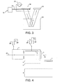
- Fig. 3 conceptually illustrates TOFMS using an orthogonal acceleration method (i.e., orthogonal acceleration TOFMS).
- An ion beam 30 created from an ion source 32 that creates ions continuously is conveyed with kinetic energies of tens of kV continuously to an orthogonal acceleration region 34.
- a pulsed voltage of about 10 kV is generated using a pulse voltage power supply 35 and applied such that the ions are accelerated in a direction orthogonal to the direction in which the ions are conveyed from the ion source.
- the times taken for the ions to reach the detector 36 after the application of the pulsed voltage are different according to the masses of the ions. Thus, mass separation is performed.
- the orthogonally accelerated ions are reflected in a reflector 38 so as to continue to the detector.
- a merit of orthogonal acceleration TOFMS is that the ion source can be installed at close to the ground potential. Therefore, in the flight space of the TOFMS, positive ions are floated at voltages of about - 5 to - 10 kV. There is the problem that these voltages are often limited by the voltage withstanding characteristics of the detector.
- an orthogonal acceleration TOFMS having: an ion source for ionizing a sample; a conductive box into which the created ions are introduced; ion acceleration means placed inside or behind the conductive box and causing the ions to be accelerated in a pulsed manner in synchronism with a signal giving a starting point of measurement; and ion detection means for detecting the ions in synchronism with the acceleration of the ions.
- the conductive box is provided with an ion injection port and an ion exit port. A voltage is applied to the conductive box. This voltage is switched in synchronism with the signal giving the starting point of the measurement.
- the switching permits the voltage to be applied to the box. After the ions leave the conductive box, the switching ceases the application of the voltage to the box.
- ion guides for preventing diffusion of the ions are mounted inside the conductive box.
- ion beam compression means for compressing the ion beam in the direction of flight of ions is mounted inside the conductive box.
- an ion reflectron field is formed between the ion acceleration means and the ion detection means.
- an electric sector field is formed between the ion acceleration means and the ion detection means.
- the conductive box and the ion source are substantially at equipotential.
- the potential of the same polarity as the polarity of analyzed ions is applied.
- both conductive box and ion source are at close to ground potential.
- the potential at the conductive box is less than - 10 kV.
- a voltage of about 10 kV or higher having the same polarity as the ions is applied to the ion acceleration means.
- the orthogonal acceleration TOFMS has: an ion source for ionizing a sample; a conductive box into which the created ions are introduced; ion acceleration means placed inside or behind the conductive box and causing the ions to be accelerated in a pulsed manner in synchronism with a signal giving a starting point of measurement; and ion detection means for detecting ions in synchronism with the acceleration of the ions.
- the conductive box is provided with an ion injection port and an ion exit port. A voltage is applied to the conductive box. This voltage is switched in synchronism with the signal giving the starting point of the measurement. Consequently, it is possible to provide the orthogonal acceleration TOFMS not affected by the voltage withstanding performance of the ion detection means.
- ions may be extracted by disposing pulsed accelerating electrodes closer to the detector than the ion beam entrance position.
- repeller pulsed electrodes and extraction pulsed electrodes may be arranged on the opposite sides of the ion beam entrance position.
- Figs. 4-8 show a first embodiment (Embodiment 1) of the present invention.
- a TOFMS orthogonal acceleration region is accommodated in a metallic box to which a voltage, known as potential lift, can be applied.
- the potential across the metallic box is uniform.
- the potential-lift wall surfaces of the portions opposite to the ion beam entrance path and of the portions of the pulsed acceleration region 2 from which ions exit are made of a mesh.
- This TOFMS is similar in configuration to the conventional reflectron TOFMS in other respects.
- the ion source, ion transport system, potential lift mechanism 1, and a pulsed accelerating electrode 3 are at close to ground potential.
- the ion beam can smoothly enter the potential lift mechanism 1 through the mesh, along incident beam position line 39.
- FIG 8 shows a timing signal (lower trace), the voltage applied to the pulsed accelerating electrode 3 (middle trace), and the voltage applied to the potential lift mechanism 1 (upper trace).
- a trigger signal is produced at an instant of time t 1 .
- a voltage is applied to the potential lift mechanism 1.
- the potential is increased from ground potential to V L (about + 10 kV) in a short time. This increases the potential of ions inside the potential lift mechanism 1 to V L .
- the ion beam from the ion source is reflected by the mesh disposed at the entrance to the potential lift mechanism. Thus, the beam cannot enter the potential lift mechanism 1.
- the voltage of V L is applied to the pulsed accelerating electrode 3 in synchronism with the application of the voltage to the potential lift mechanism 1.
- the ion beam in the potential lift mechanism 1 whose potential has been increased to V L goes further and reaches the pulsed acceleration region 2.
- the ion beam reaches the pulsed acceleration region 2 at instant of time of t 2 . If a pulsed voltage of V P is applied to the pulsed accelerating electrode 3 at the instant t 2 , the ion beam passes through the mesh and is pushed out of the potential lift mechanism 1, and then measurement of the flight times of the ions is started.
- the voltage V P is so set that V P - V L is higher than 1 kV and lower than 10 kV.
- the ion beam is accelerated when it passes through the region surrounded by the pulsed acceleration electrode 3 set to V P , a first accelerating electrode 4 held to a voltage close to V L , and a second accelerating electrode 5 held close to ground potential.
- the beam is reflected by a reflectron field 6 and reaches a detector 7.
- the potential at the potential lift mechanism 1 may be returned to ground potential at an instant of time t 3 , i.e., after the ion beam has passed through the first accelerating electrode 4.
- the ion beam from the ion source again passes through the mesh on the potential lift mechanism 1 and begins to pass into the potential lift mechanism 1.
- the potential at the pulsed accelerating electrode 3 is again returned to the potential close to ground potential in synchronism with variation in potential at the potential lift mechanism 1.
- Fig. 9 illustrates a second embodiment (Embodiment 2) of the present invention.
- a metallic box to which a voltage, known as potential lift, can be applied is placed ahead of the orthogonal acceleration region of a TOFMS. Potential across the metallic box is uniform.
- the potential at the ion acceleration region 2 is previously set close to the accelerating potential.
- An ion transport system such as ion guides may be mounted in the potential lift mechanism.
- the TOFMS of the second embodiment is similar to the reflectron TOFMS of the first embodiment in other respects.
- the potential-lift wall surfaces of the portions opposite to the ion beam entrance path and of the portions opposite to the pulsed acceleration region 2 are made of a mesh.
- the ion source, ion transport system, and potential lift mechanism 1 are set close to ground potential.
- the ion beam can smoothly enter the potential lift mechanism 1 through the mesh.
- a voltage of V L (about + 10 kV) is applied to the pulsed accelerating electrode 3 and to the first accelerating electrode 4.
- the ion beam has entered to some extent.
- a trigger signal is produced.
- a voltage is applied to the potential lift mechanism 1.
- the potential is increased from ground potential to V L in a short time. This increases the potential of ions inside the potential lift mechanism 1 to V L .
- the ion beam from the ion source is reflected by the mesh disposed at the entrance to the potential lift mechanism. Thus, the beam cannot enter the potential lift mechanism 1.
- the ion beam in the potential lift mechanism 1 whose potential has been increased to V L goes further and reaches the pulsed acceleration region 2. Because the potential lift mechanism 1 and pulsed acceleration region 2 are at the potential V L , the ion beam smoothly moves from the potential lift mechanism 1 toward the pulsed acceleration region 2.
- the ion beam reaches the pulsed acceleration region 2 at instant of time of t 2 - If a pulsed voltage of V P of about + 10 kV or higher is applied to the pulsed accelerating electrode 3 at the instant t 2 , the ion beam passes through the mesh and is pushed out of the ion acceleration region 2 , and then measurement of the flight times of the ions is started.
- the potential at the potential lift mechanism 1 may be returned to ground potential at the instant of time t 3 , i. e. , after the ion beam has passed through the first accelerating electrode 4.
- the ion beam from the ion source again passes through the mesh on the potential lift mechanism 1 and begins to pass into the potential lift mechanism 1.
- the pulsed voltage V P When the pulsed voltage V P is applied to the pulsed accelerating electrode 3, the ion beam is accelerated when it passes through the region surrounded by the pulsed acceleration electrode 3 set to V P , first accelerating electrode 4 held to a voltage close to V L , and second accelerating electrode 5 held closetogroundpotential. Thebeamisreflectedbythereflectron field and reaches the detector 7. After the ions exit from the ion acceleration region 6, the potential at the pulsed accelerating electrode 3 is returned to V L .
- the third embodiment provides modifications of Embodiments 1 and 2.
- Ion beam transport means including lenses is disposed in the potential lift mechanism.
- the fourth embodiment provides modifications of Embodiments 1 to 3.
- Ionbeamcompressionmeans capable of applying a pulsed voltage in the direction of transportation of a continuous beam is mounted for the lenses in the potential lift mechanism.
- Figs. 11-13 show the fourth embodiment of the present invention.
- a metallic box to which a voltage, known as potential lift, can be applied is placed ahead of the orthogonal acceleration region of a TOFMS. Potential across the metallic box is uniform.
- Compression electrodes 8 for compressing the ion beam in the direction of the axis of the beam is mounted in the box.
- the compression electrodes are made of a planar mesh parallel to the plane perpendicular to the axis of the ion beam.
- This TOFMS is similar in configuration with the reflectron TOFMS of Embodiment 1 in other respects.
- the present embodiment operates as follows. First, an ion beam 40 produced from an ion source (not shown) that creates ions continuously reaches the potential lift mechanism 1 via the ion transport system including ion guides (not shown).
- the potential-lift wall surfaces of the portions opposite to the ion beam entrance path and of the portions opposite to the pulsed accelerating portion/region 2 are made of a mesh.
- the ion source, ion transport system, and potential lift mechanism 1 are set close to ground potential.
- the ion beam can smoothly enter the potential lift mechanism 1 through the mesh.
- the voltage V L is applied to the pulsed accelerating electrode 3 and to the first accelerating electrode 4.
- the ion beam has entered to some extent.
- a trigger signal is produced.
- a voltage is applied to the potential lift mechanism 1.
- the potential is increased from ground potential to V L (about + 10 kV) in a short time. This increases the potential of ions inside the potential lift mechanism 1 to V L .
- the ion beam from the ion source is reflected by the mesh disposed at the entrance to the potential lift mechanism. Thus, the beam cannot enter the potential lift mechanism 1.
- a pulsed voltage of V C (V L + tens of V (i.e., higher than 10 V and lower than 100V)) is applied to the compression electrodes 8 at the same time when the potential at the potential lift mechanism 1 is increased to V L or at instant t 4 (i.e., slightly later) to accelerate the ions toward the ion acceleration region 2.
- the pulsed voltage V C is so set as to substantially balance the ion transport energies of tens of eV.
- the ion beam moves through the potential lift mechanism 1 while at the increased potential V L .
- the beam acquires higher kinetic energy. Then, the beam enters the ion acceleration region 2, where the beam can be compressed in the direction of the axis of the beam.
- the potential lift mechanism 1 is designed to be longer than the ion acceleration region 2 in the direction of axis of the beam, the ion beam that is spatially larger than the intrinsic space of the ion acceleration region 2 can be used for flight time measurements as shown in Fig. 12 . Hence, the efficiency of utilization of the ions is improved.
- the potential at the potential lift mechanism 1 may be again returned to ground potential after the ion beam has passed through the first accelerating electrode 4. In consequence, the ion beam from the ion source again passes through the mesh on the potential lift mechanism 1 and begins to pass into the potential lift mechanism 1.
- the pulsed voltage V P When the pulsed voltage V P is applied to the pulsed accelerating electrode 3, the ion beam is accelerated when it passes through the region surrounded by the pulsed acceleration electrode 3 set to V P , first accelerating electrode 4 held to a voltage close to V L , and second accelerating electrode 5 held closetogroundpotential.
- Thebeamisreflectedbythereflectron field 6 and reaches the detector 7.
- the potential at the pulsed accelerating electrode 3 is again returned to V L .
- the present invent ion can find wide acceptance in orthogonal acceleration TOF mass spectrometry.
Landscapes
- Chemical & Material Sciences (AREA)
- Analytical Chemistry (AREA)
- Other Investigation Or Analysis Of Materials By Electrical Means (AREA)
Abstract
Description
- The present invention relates to an orthogonal acceleration time-of-flight mass spectrometer for use in quantitative analysis of trace compounds, qualitative simultaneous analysis of trace compounds, and structural analysis of sample ions.
- A time-of-flight mass spectrometer is an apparatus for finding the mass-to-charge ratios of ions from the times taken for the ions to reach a detector after a given amount of energy is given to the ions such that they accelerate and fly. In TOFMS, ions are accelerated by a constant pulsed voltage Va. At this time, the velocity v of each ion is given as follows from the law of energy conservation:


where m is the mass of the ion, q is the electric charge of the ion, and e is the elementary electric charge. The ion reaches a detector spaced a given distance of L after a lapse of time T (flight time).
It can be seen from Eq. (3) that the flight time Tvaries depending on the mass m of the ion. TOFMS is an apparatus that isolates masses utilizing this fact. One example of linear TOFMS is shown inFig. 1 . Apulse ion source 10 including apulse voltage generator 12 is a source ofions 14 which travel todetector 16 according toarrow 18, with ions of smaller mass arriving at the detector first. Furthermore, reflectron TOFMS has enjoyed wide acceptance because the apparatus permits improvement of energy convergence and increase in flight distance by placing a reflectron field between an ion source and a detector. One example of reflectron TOFMS is shown inFig. 2 . Using reference numerals in common withfigure 1 where appropriate, the reflectron, TOMS also includes apulse ion source 10 having apulse voltage generator 12. Theions 14 travel todetector 16 according toarrow 20, which indicates the curved path of theions 14 withinreflector 22. Again, ions of smaller mass arrive at the detector first. - TOFMS must accelerate ions in a pulsed manner by the ion accelerating region in order to analyze variations in mass-to-charge ratio as the elapsed times from a starting point in time. Therefore, TOFMS has very good compatibility with an ionization method in which pulsed ionization is performed such as by laser irradiation. However, mass spectrometry ionization methods include numerous ionization methods of producing ions continuously such as electron impact (EI) ionization, chemical ionization (CI) ionization, electrospray ionization (ESI), and atmospheric-pressure chemical ionization (APCI). Orthogonal acceleration time-of-flight mass spectrometry has been developed to combine these ionization methods with TOFMS.
-
Fig. 3 conceptually illustrates TOFMS using an orthogonal acceleration method (i.e., orthogonal acceleration TOFMS). Anion beam 30 created from anion source 32 that creates ions continuously is conveyed with kinetic energies of tens of kV continuously to anorthogonal acceleration region 34. In the orthogonal acceleration region, a pulsed voltage of about 10 kV is generated using a pulsevoltage power supply 35 and applied such that the ions are accelerated in a direction orthogonal to the direction in which the ions are conveyed from the ion source. The times taken for the ions to reach thedetector 36 after the application of the pulsed voltage are different according to the masses of the ions. Thus, mass separation is performed. Infigure 3 the orthogonally accelerated ions are reflected in areflector 38 so as to continue to the detector. - A merit of orthogonal acceleration TOFMS is that the ion source can be installed at close to the ground potential. Therefore, in the flight space of the TOFMS, positive ions are floated at voltages of about - 5 to - 10 kV. There is the problem that these voltages are often limited by the voltage withstanding characteristics of the detector.
- Furthermore, there isamethodof coupling a floated detector to a data collection system that is at ground potential by the use of capacitors. In this method, if high-intensity ions are detected, the baseline of the spectrumsags immediately thereafter. This presents the problem that the quantitativeness is severely deteriorated.
- In view of the foregoing, it would be desirable to provide an orthogonal acceleration TOFMS that is not affected by the voltage withstanding performance of the ion detector. The problem with the conventional orthogonal acceleration (oa-) TOFMS can be solved by introducing a potential lifting mechanism (see
patent reference 1,JP patent no. 3,354,427 - (1) The ion source and detection system can be placed at close to ground potential and so it is easy to handle the apparatus.
- (2) Because the performance of TOFMS is affected by values obtained by dividing the initial energies creating a distribution by the accelerating voltage, if the initial energies are uniform across the ion acceleration region, those values can be reduced by setting the accelerating voltage to a higher value.
- (3) It can be expected that the sensitivity of the detector will be improved by removing the restrictions imposed on the ion acceleration voltage.
- (4) It is possible to avoid the problem with the capacitive coupling of the conventional detection system in which the voltage is floated. The quantitativeness can be improved.
- This object is achieved in accordance with the teachings of the present invention by an orthogonal acceleration TOFMS having: an ion source for ionizing a sample; a conductive box into which the created ions are introduced; ion acceleration means placed inside or behind the conductive box and causing the ions to be accelerated in a pulsed manner in synchronism with a signal giving a starting point of measurement; and ion detection means for detecting the ions in synchronism with the acceleration of the ions. The conductive box is provided with an ion injection port and an ion exit port. A voltage is applied to the conductive box. This voltage is switched in synchronism with the signal giving the starting point of the measurement.
- In one feature of the invention, after the ions enter the conductive box, the switching permits the voltage to be applied to the box. After the ions leave the conductive box, the switching ceases the application of the voltage to the box.
- In another feature of the invention, ion guides for preventing diffusion of the ions are mounted inside the conductive box.
- In a further feature of the invention, ion beam compression means for compressing the ion beam in the direction of flight of ions is mounted inside the conductive box.
- In a still other feature of the invention, an ion reflectron field is formed between the ion acceleration means and the ion detection means.
- In an additional feature of the invention, an electric sector field is formed between the ion acceleration means and the ion detection means.
- In a yet other feature of the invention, when no potential is applied to the box, the conductive box and the ion source are substantially at equipotential. When a potential is permitted to be applied to the box, the potential of the same polarity as the polarity of analyzed ions is applied.
- In a still additional feature of the invention, when no potential is applied to the conductive box, both conductive box and ion source are at close to ground potential.
- In a further additional feature of the invention, when a potential is permitted to be applied to the conductive box, if ions to be analyzed are positive ions, the potential at the conductive box is less than + 10 kV.
- In an additional feature of the invention, when a potential is permitted to be applied to the conductive box, if ions to be analyzed are negative ions, the potential at the conductive box is less than - 10 kV.
- In an additional feature of the invention, when ions are accelerated, a voltage of about 10 kV or higher having the same polarity as the ions is applied to the ion acceleration means.
- The orthogonal acceleration TOFMS according to the present invention has: an ion source for ionizing a sample; a conductive box into which the created ions are introduced; ion acceleration means placed inside or behind the conductive box and causing the ions to be accelerated in a pulsed manner in synchronism with a signal giving a starting point of measurement; and ion detection means for detecting ions in synchronism with the acceleration of the ions. The conductive box is provided with an ion injection port and an ion exit port. A voltage is applied to the conductive box. This voltage is switched in synchronism with the signal giving the starting point of the measurement. Consequently, it is possible to provide the orthogonal acceleration TOFMS not affected by the voltage withstanding performance of the ion detection means.
- These and other objects and advantages of the present invention will become more apparent as the following description proceeds.
-
-
Fig. 1 is a diagram of one conventional linear TOF (time-of-flight) mass spectrometer; -
Fig. 2 is a diagram of a conventional reflectron TOF mass spectrometer; -
Fig. 3 is a diagram of a conventional reflectron, orthogonal acceleration TOF mass spectrometer; -
Fig. 4 is a diagram of a TOF mass spectrometer according to the present invention; -
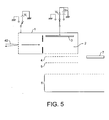
Fig. 5 is a diagram of the TOF mass spectrometer offigure 4 , showing switching of the potential of the potential-lift mechanism into the neighbourhood of the acceleration voltage; -
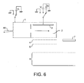
Fig. 6 is a diagram of the TOF mass spectrometer offigure 4 , showing impressing of a pulwse voltage on the accelerating electrode; -
Fig. 7 is a diagram of the TOF mass spectrometer offigure 4 , showing switching of the potential of the potential-lift mechanism into the neighbourhood of the ground potential; -
Fig. 8 is a diagram illustrating one method of controlling potentials in the TOF mass spectrometer offigures 4 to 7 ; -
Fig. 9 is a diagram illustrating another TOF mass spectrometer according to the invention; -
Fig. 10 is a timing chart illustrating a method of controlling potentials in the TOF mass spectrometer offigure 9 ; -
Fig. 11 is a diagram of a still further TOF mass spectrometer according to the invention; -
Fig. 12 is a diagram the TOF mass spectrometer offigure 11 , showing the compressed ion beam; and -
Fig. 13 is a diagram illustrating a method of controlling potentials in the TOF mass spectrometer offigures 11 and12 . - The preferred embodiments of the present invention are hereinafter described with reference to the drawings. In all the embodiments described below, it is assumed that positive ions are measured. Negative ions can be measured by reversing the polarity of the voltage. Furthermore, in all the embodiments described below, a reflectron TOFMS in which a reflectron field is placed between an ion acceleration region and a detector is taken as an example. The present invention can be applied to any type of TOFMS including linear TOFMS having no reflectron field and spiral TOFMS in which at least one electric sector field is placed between an ion acceleration region and a detector. In addition, in all the embodiments described below, ions are pushed by pulsed accelerating electrodes. If an equivalent electric accelerating field is obtained, ions may be extracted by disposing pulsed accelerating electrodes closer to the detector than the ion beam entrance position. Alternatively, repeller pulsed electrodes and extraction pulsed electrodes may be arranged on the opposite sides of the ion beam entrance position.
-
Figs. 4-8 show a first embodiment (Embodiment 1) of the present invention. In the present embodiment, a TOFMS orthogonal acceleration region is accommodated in a metallic box to which a voltage, known as potential lift, can be applied. The potential across the metallic box is uniform. The potential-lift wall surfaces of the portions opposite to the ion beam entrance path and of the portions of thepulsed acceleration region 2 from which ions exit are made of a mesh. This TOFMS is similar in configuration to the conventional reflectron TOFMS in other respects. - The present embodiment operates as follows. First, as shown in
Fig. 4 , anion beam 40 produced from an ion source (not shown) that creates ions continuously reaches apotential lift mechanism 1 via an ion transport system including ion guides (not shown). - The ion source, ion transport system,
potential lift mechanism 1, and a pulsed acceleratingelectrode 3 are at close to ground potential. The ion beam can smoothly enter thepotential lift mechanism 1 through the mesh, along incidentbeam position line 39. -
Figure 8 shows a timing signal (lower trace), the voltage applied to the pulsed accelerating electrode 3 (middle trace), and the voltage applied to the potential lift mechanism 1 (upper trace). As shown inFigs. 5 and8 , at an instant of time t1, the ion beam has entered to some extent. At this instant, a trigger signal is produced. In synchronism with the trigger signal, a voltage is applied to thepotential lift mechanism 1. The potential is increased from ground potential to VL (about + 10 kV) in a short time. This increases the potential of ions inside thepotential lift mechanism 1 to VL. During this interval, the ion beam from the ion source is reflected by the mesh disposed at the entrance to the potential lift mechanism. Thus, the beam cannot enter thepotential lift mechanism 1. At this time, the voltage of VL is applied to the pulsed acceleratingelectrode 3 in synchronism with the application of the voltage to thepotential lift mechanism 1. - Then, as shown in
Figs. 6 and8 , the ion beam in thepotential lift mechanism 1 whose potential has been increased to VL goes further and reaches thepulsed acceleration region 2. The ion beam reaches thepulsed acceleration region 2 at instant of time of t2. If a pulsed voltage of VP is applied to the pulsed acceleratingelectrode 3 at the instant t2, the ion beam passes through the mesh and is pushed out of thepotential lift mechanism 1, and then measurement of the flight times of the ions is started. The voltage VP is so set that VP - VL is higher than 1 kV and lower than 10 kV. - When the pulsed voltage VP is applied to the pulsed accelerating
electrode 3, the ion beam is accelerated when it passes through the region surrounded by thepulsed acceleration electrode 3 set to VP, a first acceleratingelectrode 4 held to a voltage close to VL, and a second acceleratingelectrode 5 held close to ground potential. The beam is reflected by areflectron field 6 and reaches adetector 7. - Then, as shown in
Fig. 8 , the potential at thepotential lift mechanism 1 may be returned to ground potential at an instant of time t3, i.e., after the ion beam has passed through the first acceleratingelectrode 4. In consequence, the ion beam from the ion source again passes through the mesh on thepotential lift mechanism 1 and begins to pass into thepotential lift mechanism 1. The potential at the pulsed acceleratingelectrode 3 is again returned to the potential close to ground potential in synchronism with variation in potential at thepotential lift mechanism 1. - Eventually, the potentials at the
potential lift mechanism 1 and pulsed acceleratingelectrode 3 vary repeatedly as each flight time measurement is made as shown inFig. 8 . Successive ion flight time measurements can be performed by repeating the operations described so far. -
Fig. 9 illustrates a second embodiment (Embodiment 2) of the present invention. In the present embodiment, a metallic box to which a voltage, known as potential lift, can be applied is placed ahead of the orthogonal acceleration region of a TOFMS. Potential across the metallic box is uniform. The potential at theion acceleration region 2 is previously set close to the accelerating potential. An ion transport system such as ion guides may be mounted in the potential lift mechanism. The TOFMS of the second embodiment is similar to the reflectron TOFMS of the first embodiment in other respects. - The present embodiment is described by referring to the timing chart of
Fig. 10 . Anion beam 40 produced from an ion source (not shown) that creates ions continuously reaches thepotential lift mechanism 1 via an ion transport system including ion guides (not shown). The potential-lift wall surfaces of the portions opposite to the ion beam entrance path and of the portions opposite to thepulsed acceleration region 2 are made of a mesh. - The ion source, ion transport system, and
potential lift mechanism 1 are set close to ground potential. The ion beam can smoothly enter thepotential lift mechanism 1 through the mesh. At this time, a voltage of VL (about + 10 kV) is applied to the pulsed acceleratingelectrode 3 and to the first acceleratingelectrode 4. - Then, at the instant of time t1, the ion beam has entered to some extent. At this instant, a trigger signal is produced. In synchronism with the trigger signal, a voltage is applied to the
potential lift mechanism 1. The potential is increased from ground potential to VL in a short time. This increases the potential of ions inside thepotential lift mechanism 1 to VL. During this interval, the ion beam from the ion source is reflected by the mesh disposed at the entrance to the potential lift mechanism. Thus, the beam cannot enter thepotential lift mechanism 1. - Then, the ion beam in the
potential lift mechanism 1 whose potential has been increased to VL goes further and reaches thepulsed acceleration region 2. Because thepotential lift mechanism 1 andpulsed acceleration region 2 are at the potential VL, the ion beam smoothly moves from thepotential lift mechanism 1 toward thepulsed acceleration region 2. - The ion beam reaches the
pulsed acceleration region 2 at instant of time of t2- If a pulsed voltage of VP of about + 10 kV or higher is applied to the pulsed acceleratingelectrode 3 at the instant t2, the ion beam passes through the mesh and is pushed out of theion acceleration region 2 , and then measurement of the flight times of the ions is started. - Then, the potential at the
potential lift mechanism 1 may be returned to ground potential at the instant of time t3, i. e. , after the ion beam has passed through the first acceleratingelectrode 4. In consequence, the ion beam from the ion source again passes through the mesh on thepotential lift mechanism 1 and begins to pass into thepotential lift mechanism 1. - When the pulsed voltage VP is applied to the pulsed accelerating
electrode 3, the ion beam is accelerated when it passes through the region surrounded by thepulsed acceleration electrode 3 set to VP, first acceleratingelectrode 4 held to a voltage close to VL, and second acceleratingelectrode 5 held closetogroundpotential. Thebeamisreflectedbythereflectron field and reaches thedetector 7. After the ions exit from theion acceleration region 6, the potential at the pulsed acceleratingelectrode 3 is returned to VL. - Eventually, the potentials at the
potential lift mechanism 1 and pulsed acceleratingelectrode 3 vary repeatedly as each flight time measurement is made as shown inFig. 10 . Successive ion flight time measurements can be performed by repeating the operations described so far. - The third embodiment provides modifications of
Embodiments - The fourth embodiment provides modifications of
Embodiments 1 to 3. Ionbeamcompressionmeans capable of applying a pulsed voltage in the direction of transportation of a continuous beam is mounted for the lenses in the potential lift mechanism. -
Figs. 11-13 show the fourth embodiment of the present invention. In the present embodiment, a metallic box to which a voltage, known as potential lift, can be applied is placed ahead of the orthogonal acceleration region of a TOFMS. Potential across the metallic box is uniform.Compression electrodes 8 for compressing the ion beam in the direction of the axis of the beam is mounted in the box. The compression electrodes are made of a planar mesh parallel to the plane perpendicular to the axis of the ion beam. This TOFMS is similar in configuration with the reflectron TOFMS ofEmbodiment 1 in other respects. - The present embodiment operates as follows. First, an
ion beam 40 produced from an ion source (not shown) that creates ions continuously reaches thepotential lift mechanism 1 via the ion transport system including ion guides (not shown). The potential-lift wall surfaces of the portions opposite to the ion beam entrance path and of the portions opposite to the pulsed accelerating portion/region 2 are made of a mesh. - The ion source, ion transport system, and
potential lift mechanism 1 are set close to ground potential. The ion beam can smoothly enter thepotential lift mechanism 1 through the mesh. At this time, the voltage VL is applied to the pulsed acceleratingelectrode 3 and to the first acceleratingelectrode 4. - Then, at the instant of time t1, the ion beam has entered to some extent. At this instant, a trigger signal is produced. In synchronism with the trigger signal, a voltage is applied to the
potential lift mechanism 1. The potential is increased from ground potential to VL (about + 10 kV) in a short time. This increases the potential of ions inside thepotential lift mechanism 1 to VL. During this interval, the ion beam from the ion source is reflected by the mesh disposed at the entrance to the potential lift mechanism. Thus, the beam cannot enter thepotential lift mechanism 1. - Then, a pulsed voltage of VC (VL + tens of V (i.e., higher than 10 V and lower than 100V)) is applied to the
compression electrodes 8 at the same time when the potential at thepotential lift mechanism 1 is increased to VL or at instant t4 (i.e., slightly later) to accelerate the ions toward theion acceleration region 2. The pulsed voltage VC is so set as to substantially balance the ion transport energies of tens of eV. - The ion beam moves through the
potential lift mechanism 1 while at the increased potential VL. As the beam is closer to the compression electrode 8 (i.e., remoter from the pulsed acceleration region 2), the beam acquires higher kinetic energy. Then, the beam enters theion acceleration region 2, where the beam can be compressed in the direction of the axis of the beam. - That is, if the
potential lift mechanism 1 is designed to be longer than theion acceleration region 2 in the direction of axis of the beam, the ion beam that is spatially larger than the intrinsic space of theion acceleration region 2 can be used for flight time measurements as shown inFig. 12 . Hence, the efficiency of utilization of the ions is improved. - If a pulsed voltage of VP of about + 10 kV or higher is applied to the pulsed accelerating
electrode 3 at the instant t2 when the ion beam reached thepulsed acceleration region 2, the ion beam passes through the mesh and is pushed out of theion acceleration region 2, and then measurement of the flight times of the ions is started. - The potential at the
potential lift mechanism 1 may be again returned to ground potential after the ion beam has passed through the first acceleratingelectrode 4. In consequence, the ion beam from the ion source again passes through the mesh on thepotential lift mechanism 1 and begins to pass into thepotential lift mechanism 1. - When the pulsed voltage VP is applied to the pulsed accelerating
electrode 3, the ion beam is accelerated when it passes through the region surrounded by thepulsed acceleration electrode 3 set to VP, first acceleratingelectrode 4 held to a voltage close to VL, and second acceleratingelectrode 5 held closetogroundpotential.Thebeamisreflectedbythereflectron field 6 and reaches thedetector 7. After the ions exit from theion acceleration region 2, the potential at the pulsed acceleratingelectrode 3 is again returned to VL. - Eventually, the potentials at the
potential lift mechanism 1 and pulsed acceleratingelectrode 3 vary repeatedly as each flight time measurement is made as shown inFig. 13 . Successive ion flight time measurements can be performed by repeating the operations described so far. - The present invent ion can find wide acceptance in orthogonal acceleration TOF mass spectrometry.
Claims (11)
- An orthogonal acceleration TOF mass spectrometer comprising:an ion source for ionizing a sample;a conductive box into which the created ions are introduced;ion acceleration means placed inside or behind the conductive box and causing the ions to be accelerated in a pulsed manner in synchronism with a signal giving a starting point of measurement; andion detection means for detecting the ions in synchronism with the acceleration of the ions;wherein the conductive box is provided with an ion injection port and an ion exit port; and
wherein a voltage is applied to the conductive box, the voltage being switched in synchronism with the signal giving the starting point of the measurement. - An orthogonal acceleration TOF mass spectrometer as set forth in claim 1, wherein after the ions enter the conductive box, said switching permits the voltage to be applied to the box, and wherein after the ions leave the conductive box, said switching ceases the application of the voltage to the box.
- An orthogonal acceleration TOF mass spectrometer as set forth in claim 1, wherein ion guides for preventing diffusion of the ions are mounted inside the conductive box.
- An orthogonal acceleration TOF mass spectrometer as set forth in claim 1, wherein ion beam compression means for compressing the ion beam in the direction of flight of ions is mounted inside the conductive box.
- An orthogonal acceleration TOF mass spectrometer as set forth in claim 1, wherein an ion reflectron field is formed between said ion acceleration means and said ion detection means.
- An orthogonal acceleration TOF mass spectrometer as set forth in claim 1, wherein an electric sector field is formed between said ion acceleration means and said ion detection means.
- An orthogonal acceleration TOF mass spectrometer as set forth in claim 1, wherein when no potential is applied to the box, the conductive box and the ion source are substantially at equipotential, and wherein when the potential is permitted to be applied to the box, the potential of the same polarity as the polarity of analyzed ions is applied.
- An orthogonal acceleration TOF mass spectrometer as set forth in claim 7, wherein when no potential is applied to the conductive box, both of the conductive box and the ion source are at close to ground potential.
- An orthogonal acceleration TOF mass spectrometer as set forth in claim 7, wherein when the potential is permitted to be applied to the conductive box, if ions to be analyzed are positive ions, the potential at the conductive box is about + 10 kV.
- An orthogonal acceleration TOF mass spectrometer as set forth in claim 7, wherein when a potential is permitted to be applied to the conductive box, if ions to be analyzed are negative ions, the potential at the conductive box is about - 10 kV.
- An orthogonal acceleration TOF mass spectrometer as set forth in claim 1, wherein when ions are accelerated, a voltage of about 10 kV or higher having the same polarity as the ions is applied to the ion acceleration means.
Applications Claiming Priority (1)
| Application Number | Priority Date | Filing Date | Title |
|---|---|---|---|
| JP2007294272A JP4922900B2 (en) | 2007-11-13 | 2007-11-13 | Vertical acceleration time-of-flight mass spectrometer |
Publications (3)
| Publication Number | Publication Date |
|---|---|
| EP2068346A2 true EP2068346A2 (en) | 2009-06-10 |
| EP2068346A3 EP2068346A3 (en) | 2010-10-13 |
| EP2068346B1 EP2068346B1 (en) | 2018-08-22 |
Family
ID=40568773
Family Applications (1)
| Application Number | Title | Priority Date | Filing Date |
|---|---|---|---|
| EP08253697.0A Active EP2068346B1 (en) | 2007-11-13 | 2008-11-12 | Orthogonal acceleration time-of-flight mas spectrometer |
Country Status (3)
| Country | Link |
|---|---|
| US (1) | US8563923B2 (en) |
| EP (1) | EP2068346B1 (en) |
| JP (1) | JP4922900B2 (en) |
Cited By (21)
| Publication number | Priority date | Publication date | Assignee | Title |
|---|---|---|---|---|
| WO2018215737A1 (en) * | 2017-05-26 | 2018-11-29 | Micromass Uk Limited | Time of flight mass analyser with spatial focussing |
| US10593533B2 (en) | 2015-11-16 | 2020-03-17 | Micromass Uk Limited | Imaging mass spectrometer |
| US10629425B2 (en) | 2015-11-16 | 2020-04-21 | Micromass Uk Limited | Imaging mass spectrometer |
| US10636646B2 (en) | 2015-11-23 | 2020-04-28 | Micromass Uk Limited | Ion mirror and ion-optical lens for imaging |
| US10741376B2 (en) | 2015-04-30 | 2020-08-11 | Micromass Uk Limited | Multi-reflecting TOF mass spectrometer |
| US10950425B2 (en) | 2016-08-16 | 2021-03-16 | Micromass Uk Limited | Mass analyser having extended flight path |
| US11049712B2 (en) | 2017-08-06 | 2021-06-29 | Micromass Uk Limited | Fields for multi-reflecting TOF MS |
| US11081332B2 (en) | 2017-08-06 | 2021-08-03 | Micromass Uk Limited | Ion guide within pulsed converters |
| US11205568B2 (en) | 2017-08-06 | 2021-12-21 | Micromass Uk Limited | Ion injection into multi-pass mass spectrometers |
| US11211238B2 (en) | 2017-08-06 | 2021-12-28 | Micromass Uk Limited | Multi-pass mass spectrometer |
| US11239067B2 (en) | 2017-08-06 | 2022-02-01 | Micromass Uk Limited | Ion mirror for multi-reflecting mass spectrometers |
| US11295944B2 (en) | 2017-08-06 | 2022-04-05 | Micromass Uk Limited | Printed circuit ion mirror with compensation |
| US11309175B2 (en) | 2017-05-05 | 2022-04-19 | Micromass Uk Limited | Multi-reflecting time-of-flight mass spectrometers |
| US11342175B2 (en) | 2018-05-10 | 2022-05-24 | Micromass Uk Limited | Multi-reflecting time of flight mass analyser |
| US11367608B2 (en) | 2018-04-20 | 2022-06-21 | Micromass Uk Limited | Gridless ion mirrors with smooth fields |
| US11587779B2 (en) | 2018-06-28 | 2023-02-21 | Micromass Uk Limited | Multi-pass mass spectrometer with high duty cycle |
| US11621156B2 (en) | 2018-05-10 | 2023-04-04 | Micromass Uk Limited | Multi-reflecting time of flight mass analyser |
| US11817303B2 (en) | 2017-08-06 | 2023-11-14 | Micromass Uk Limited | Accelerator for multi-pass mass spectrometers |
| US11848185B2 (en) | 2019-02-01 | 2023-12-19 | Micromass Uk Limited | Electrode assembly for mass spectrometer |
| US11881387B2 (en) | 2018-05-24 | 2024-01-23 | Micromass Uk Limited | TOF MS detection system with improved dynamic range |
| US12205813B2 (en) | 2019-03-20 | 2025-01-21 | Micromass Uk Limited | Multiplexed time of flight mass spectrometer |
Families Citing this family (4)
| Publication number | Priority date | Publication date | Assignee | Title |
|---|---|---|---|---|
| JP5314603B2 (en) * | 2010-01-15 | 2013-10-16 | 日本電子株式会社 | Time-of-flight mass spectrometer |
| GB2484136B (en) * | 2010-10-01 | 2015-09-16 | Thermo Fisher Scient Bremen | Method and apparatus for improving the throughput of a charged particle analysis system |
| JP6437002B2 (en) * | 2013-12-24 | 2018-12-12 | ディーエイチ テクノロジーズ デベロップメント プライベート リミテッド | High-speed polarity switch time-of-flight mass spectrometer |
| US10475635B2 (en) * | 2016-03-18 | 2019-11-12 | Shimadzu Corporation | Voltage application method, voltage application device, and time-of-flight mass spectrometer |
Citations (3)
| Publication number | Priority date | Publication date | Assignee | Title |
|---|---|---|---|---|
| JP3354427B2 (en) | 1997-03-28 | 2002-12-09 | 日本電子株式会社 | Time-of-flight mass spectrometer |
| JP2007242425A (en) | 2006-03-09 | 2007-09-20 | Hitachi High-Technologies Corp | Mass spectrometer |
| DE102006016896A1 (en) | 2006-04-11 | 2007-10-18 | Bruker Daltonik Gmbh | Flight time mass spectrometer operating method, involves mass-selectively obtaining portions of ions from ion storage, and supplying ion portions to pulser, where part of high frequency ion guidance system is operated as ion storage |
Family Cites Families (14)
| Publication number | Priority date | Publication date | Assignee | Title |
|---|---|---|---|---|
| US5206506A (en) * | 1991-02-12 | 1993-04-27 | Kirchner Nicholas J | Ion processing: control and analysis |
| JPH10134764A (en) * | 1996-11-01 | 1998-05-22 | Jeol Ltd | Mass spectrometer |
| AU2463299A (en) * | 1998-01-23 | 1999-08-09 | Analytica Of Branford, Inc. | Mass spectrometry from surfaces |
| US6348688B1 (en) * | 1998-02-06 | 2002-02-19 | Perseptive Biosystems | Tandem time-of-flight mass spectrometer with delayed extraction and method for use |
| DE19856014C2 (en) * | 1998-12-04 | 2000-12-14 | Bruker Daltonik Gmbh | Daughter ion spectra with time-of-flight mass spectrometers |
| JP2001176444A (en) * | 1999-12-15 | 2001-06-29 | Jeol Ltd | Vertical acceleration time-of-flight mass spectrometer |
| US6683301B2 (en) * | 2001-01-29 | 2004-01-27 | Analytica Of Branford, Inc. | Charged particle trapping in near-surface potential wells |
| US20060076482A1 (en) * | 2002-12-13 | 2006-04-13 | Hobbs Steven E | High throughput systems and methods for parallel sample analysis |
| JP4980583B2 (en) * | 2004-05-21 | 2012-07-18 | 日本電子株式会社 | Time-of-flight mass spectrometry method and apparatus |
| EP1759402B1 (en) * | 2004-05-21 | 2015-07-08 | Craig M. Whitehouse | Rf surfaces and rf ion guides |
| US20050269508A1 (en) * | 2004-06-03 | 2005-12-08 | Lippa Timothy P | Apparatus and methods for detecting compounds using mass spectra |
| JP4649234B2 (en) * | 2004-07-07 | 2011-03-09 | 日本電子株式会社 | Vertical acceleration time-of-flight mass spectrometer |
| JP4594138B2 (en) * | 2005-03-16 | 2010-12-08 | 日本電子株式会社 | Time-of-flight mass spectrometer |
| JP4248540B2 (en) * | 2005-11-30 | 2009-04-02 | 株式会社日立ハイテクノロジーズ | Mass spectrometer and measurement system using the same |
-
2007
- 2007-11-13 JP JP2007294272A patent/JP4922900B2/en active Active
-
2008
- 2008-11-12 EP EP08253697.0A patent/EP2068346B1/en active Active
- 2008-11-12 US US12/269,259 patent/US8563923B2/en not_active Expired - Fee Related
Patent Citations (3)
| Publication number | Priority date | Publication date | Assignee | Title |
|---|---|---|---|---|
| JP3354427B2 (en) | 1997-03-28 | 2002-12-09 | 日本電子株式会社 | Time-of-flight mass spectrometer |
| JP2007242425A (en) | 2006-03-09 | 2007-09-20 | Hitachi High-Technologies Corp | Mass spectrometer |
| DE102006016896A1 (en) | 2006-04-11 | 2007-10-18 | Bruker Daltonik Gmbh | Flight time mass spectrometer operating method, involves mass-selectively obtaining portions of ions from ion storage, and supplying ion portions to pulser, where part of high frequency ion guidance system is operated as ion storage |
Cited By (24)
| Publication number | Priority date | Publication date | Assignee | Title |
|---|---|---|---|---|
| US10741376B2 (en) | 2015-04-30 | 2020-08-11 | Micromass Uk Limited | Multi-reflecting TOF mass spectrometer |
| US10593533B2 (en) | 2015-11-16 | 2020-03-17 | Micromass Uk Limited | Imaging mass spectrometer |
| US10629425B2 (en) | 2015-11-16 | 2020-04-21 | Micromass Uk Limited | Imaging mass spectrometer |
| US10636646B2 (en) | 2015-11-23 | 2020-04-28 | Micromass Uk Limited | Ion mirror and ion-optical lens for imaging |
| US10950425B2 (en) | 2016-08-16 | 2021-03-16 | Micromass Uk Limited | Mass analyser having extended flight path |
| US11309175B2 (en) | 2017-05-05 | 2022-04-19 | Micromass Uk Limited | Multi-reflecting time-of-flight mass spectrometers |
| GB2563571B (en) * | 2017-05-26 | 2023-05-24 | Micromass Ltd | Time of flight mass analyser with spatial focussing |
| US11328920B2 (en) | 2017-05-26 | 2022-05-10 | Micromass Uk Limited | Time of flight mass analyser with spatial focussing |
| WO2018215737A1 (en) * | 2017-05-26 | 2018-11-29 | Micromass Uk Limited | Time of flight mass analyser with spatial focussing |
| US11756782B2 (en) | 2017-08-06 | 2023-09-12 | Micromass Uk Limited | Ion mirror for multi-reflecting mass spectrometers |
| US11081332B2 (en) | 2017-08-06 | 2021-08-03 | Micromass Uk Limited | Ion guide within pulsed converters |
| US11295944B2 (en) | 2017-08-06 | 2022-04-05 | Micromass Uk Limited | Printed circuit ion mirror with compensation |
| US11049712B2 (en) | 2017-08-06 | 2021-06-29 | Micromass Uk Limited | Fields for multi-reflecting TOF MS |
| US11211238B2 (en) | 2017-08-06 | 2021-12-28 | Micromass Uk Limited | Multi-pass mass spectrometer |
| US11817303B2 (en) | 2017-08-06 | 2023-11-14 | Micromass Uk Limited | Accelerator for multi-pass mass spectrometers |
| US11239067B2 (en) | 2017-08-06 | 2022-02-01 | Micromass Uk Limited | Ion mirror for multi-reflecting mass spectrometers |
| US11205568B2 (en) | 2017-08-06 | 2021-12-21 | Micromass Uk Limited | Ion injection into multi-pass mass spectrometers |
| US11367608B2 (en) | 2018-04-20 | 2022-06-21 | Micromass Uk Limited | Gridless ion mirrors with smooth fields |
| US11621156B2 (en) | 2018-05-10 | 2023-04-04 | Micromass Uk Limited | Multi-reflecting time of flight mass analyser |
| US11342175B2 (en) | 2018-05-10 | 2022-05-24 | Micromass Uk Limited | Multi-reflecting time of flight mass analyser |
| US11881387B2 (en) | 2018-05-24 | 2024-01-23 | Micromass Uk Limited | TOF MS detection system with improved dynamic range |
| US11587779B2 (en) | 2018-06-28 | 2023-02-21 | Micromass Uk Limited | Multi-pass mass spectrometer with high duty cycle |
| US11848185B2 (en) | 2019-02-01 | 2023-12-19 | Micromass Uk Limited | Electrode assembly for mass spectrometer |
| US12205813B2 (en) | 2019-03-20 | 2025-01-21 | Micromass Uk Limited | Multiplexed time of flight mass spectrometer |
Also Published As
| Publication number | Publication date |
|---|---|
| EP2068346B1 (en) | 2018-08-22 |
| JP2009123422A (en) | 2009-06-04 |
| US8563923B2 (en) | 2013-10-22 |
| EP2068346A3 (en) | 2010-10-13 |
| JP4922900B2 (en) | 2012-04-25 |
| US20090121130A1 (en) | 2009-05-14 |
Similar Documents
| Publication | Publication Date | Title |
|---|---|---|
| EP2068346B1 (en) | Orthogonal acceleration time-of-flight mas spectrometer | |
| US12131895B2 (en) | Time of flight mass analyser with spatial focussing | |
| EP0917728B1 (en) | Ion storage time-of-flight mass spectrometer | |
| US9972480B2 (en) | Pulsed ion guides for mass spectrometers and related methods | |
| US6661001B2 (en) | Extended bradbury-nielson gate | |
| CN103650099B (en) | The targeting analysis of tandem mass spectrometry | |
| CN101802966B (en) | mass spectrometer | |
| US8013290B2 (en) | Method and apparatus for avoiding undesirable mass dispersion of ions in flight | |
| US6852972B2 (en) | Mass spectrometer | |
| CN1833300B (en) | Obtaining tandem mass spectrometry data for a plurality of parent ions in an ion population | |
| US6469295B1 (en) | Multiple reflection time-of-flight mass spectrometer | |
| US7205538B2 (en) | Mass spectrometer | |
| JP3971958B2 (en) | Mass spectrometer | |
| US7064319B2 (en) | Mass spectrometer | |
| US7087897B2 (en) | Mass spectrometer | |
| JP3219434B2 (en) | Tandem mass spectrometry system | |
| JP4033133B2 (en) | Mass spectrometer | |
| US5753909A (en) | High resolution postselector for time-of-flight mass spectrometery | |
| US9627190B2 (en) | Energy resolved time-of-flight mass spectrometry | |
| JP2005353428A (en) | Ion trap / time-of-flight mass spectrometer and mass spectrometry method | |
| WO2005114703A2 (en) | Tandem-in-time and tandem-in-space mass and ion mobility spectrometer and method | |
| EP2439764A2 (en) | Tandem time-of-flight mass spectrometer | |
| US20010054684A1 (en) | Surface induced dissociation with pulsed ion extraction | |
| JP5243977B2 (en) | Vertical acceleration time-of-flight mass spectrometer | |
| JP2002532845A (en) | In-line reflection time-of-flight mass spectrometer for molecular structure analysis using collision-induced dissociation |
Legal Events
| Date | Code | Title | Description |
|---|---|---|---|
| PUAI | Public reference made under article 153(3) epc to a published international application that has entered the european phase |
Free format text: ORIGINAL CODE: 0009012 |
|
| AK | Designated contracting states |
Kind code of ref document: A2 Designated state(s): AT BE BG CH CY CZ DE DK EE ES FI FR GB GR HR HU IE IS IT LI LT LU LV MC MT NL NO PL PT RO SE SI SK TR |
|
| AX | Request for extension of the european patent |
Extension state: AL BA MK RS |
|
| PUAL | Search report despatched |
Free format text: ORIGINAL CODE: 0009013 |
|
| AK | Designated contracting states |
Kind code of ref document: A3 Designated state(s): AT BE BG CH CY CZ DE DK EE ES FI FR GB GR HR HU IE IS IT LI LT LU LV MC MT NL NO PL PT RO SE SI SK TR |
|
| AX | Request for extension of the european patent |
Extension state: AL BA MK RS |
|
| 17P | Request for examination filed |
Effective date: 20110405 |
|
| AKX | Designation fees paid |
Designated state(s): AT BE BG CH CY CZ DE DK EE ES FI FR GB GR HR HU IE IS IT LI LT LU LV MC MT NL NO PL PT RO SE SI SK TR |
|
| 17Q | First examination report despatched |
Effective date: 20130605 |
|
| RIC1 | Information provided on ipc code assigned before grant |
Ipc: H01J 49/00 20060101ALI20160830BHEP Ipc: H01J 49/40 20060101AFI20160830BHEP Ipc: H01J 49/02 20060101ALI20160830BHEP |
|
| GRAP | Despatch of communication of intention to grant a patent |
Free format text: ORIGINAL CODE: EPIDOSNIGR1 |
|
| INTG | Intention to grant announced |
Effective date: 20180308 |
|
| GRAS | Grant fee paid |
Free format text: ORIGINAL CODE: EPIDOSNIGR3 |
|
| GRAA | (expected) grant |
Free format text: ORIGINAL CODE: 0009210 |
|
| AK | Designated contracting states |
Kind code of ref document: B1 Designated state(s): AT BE BG CH CY CZ DE DK EE ES FI FR GB GR HR HU IE IS IT LI LT LU LV MC MT NL NO PL PT RO SE SI SK TR |
|
| REG | Reference to a national code |
Ref country code: GB Ref legal event code: FG4D |
|
| REG | Reference to a national code |
Ref country code: CH Ref legal event code: EP |
|
| REG | Reference to a national code |
Ref country code: DE Ref legal event code: R096 Ref document number: 602008056583 Country of ref document: DE |
|
| REG | Reference to a national code |
Ref country code: AT Ref legal event code: REF Ref document number: 1033427 Country of ref document: AT Kind code of ref document: T Effective date: 20180915 |
|
| REG | Reference to a national code |
Ref country code: IE Ref legal event code: FG4D |
|
| REG | Reference to a national code |
Ref country code: NL Ref legal event code: MP Effective date: 20180822 |
|
| REG | Reference to a national code |
Ref country code: LT Ref legal event code: MG4D |
|
| PG25 | Lapsed in a contracting state [announced via postgrant information from national office to epo] |
Ref country code: IS Free format text: LAPSE BECAUSE OF FAILURE TO SUBMIT A TRANSLATION OF THE DESCRIPTION OR TO PAY THE FEE WITHIN THE PRESCRIBED TIME-LIMIT Effective date: 20181222 Ref country code: SE Free format text: LAPSE BECAUSE OF FAILURE TO SUBMIT A TRANSLATION OF THE DESCRIPTION OR TO PAY THE FEE WITHIN THE PRESCRIBED TIME-LIMIT Effective date: 20180822 Ref country code: FI Free format text: LAPSE BECAUSE OF FAILURE TO SUBMIT A TRANSLATION OF THE DESCRIPTION OR TO PAY THE FEE WITHIN THE PRESCRIBED TIME-LIMIT Effective date: 20180822 Ref country code: GR Free format text: LAPSE BECAUSE OF FAILURE TO SUBMIT A TRANSLATION OF THE DESCRIPTION OR TO PAY THE FEE WITHIN THE PRESCRIBED TIME-LIMIT Effective date: 20181123 Ref country code: NO Free format text: LAPSE BECAUSE OF FAILURE TO SUBMIT A TRANSLATION OF THE DESCRIPTION OR TO PAY THE FEE WITHIN THE PRESCRIBED TIME-LIMIT Effective date: 20181122 Ref country code: NL Free format text: LAPSE BECAUSE OF FAILURE TO SUBMIT A TRANSLATION OF THE DESCRIPTION OR TO PAY THE FEE WITHIN THE PRESCRIBED TIME-LIMIT Effective date: 20180822 Ref country code: BG Free format text: LAPSE BECAUSE OF FAILURE TO SUBMIT A TRANSLATION OF THE DESCRIPTION OR TO PAY THE FEE WITHIN THE PRESCRIBED TIME-LIMIT Effective date: 20181122 Ref country code: LT Free format text: LAPSE BECAUSE OF FAILURE TO SUBMIT A TRANSLATION OF THE DESCRIPTION OR TO PAY THE FEE WITHIN THE PRESCRIBED TIME-LIMIT Effective date: 20180822 |
|
| REG | Reference to a national code |
Ref country code: AT Ref legal event code: MK05 Ref document number: 1033427 Country of ref document: AT Kind code of ref document: T Effective date: 20180822 |
|
| PG25 | Lapsed in a contracting state [announced via postgrant information from national office to epo] |
Ref country code: LV Free format text: LAPSE BECAUSE OF FAILURE TO SUBMIT A TRANSLATION OF THE DESCRIPTION OR TO PAY THE FEE WITHIN THE PRESCRIBED TIME-LIMIT Effective date: 20180822 Ref country code: HR Free format text: LAPSE BECAUSE OF FAILURE TO SUBMIT A TRANSLATION OF THE DESCRIPTION OR TO PAY THE FEE WITHIN THE PRESCRIBED TIME-LIMIT Effective date: 20180822 Ref country code: ES Free format text: LAPSE BECAUSE OF FAILURE TO SUBMIT A TRANSLATION OF THE DESCRIPTION OR TO PAY THE FEE WITHIN THE PRESCRIBED TIME-LIMIT Effective date: 20180822 |
|
| PG25 | Lapsed in a contracting state [announced via postgrant information from national office to epo] |
Ref country code: RO Free format text: LAPSE BECAUSE OF FAILURE TO SUBMIT A TRANSLATION OF THE DESCRIPTION OR TO PAY THE FEE WITHIN THE PRESCRIBED TIME-LIMIT Effective date: 20180822 Ref country code: CZ Free format text: LAPSE BECAUSE OF FAILURE TO SUBMIT A TRANSLATION OF THE DESCRIPTION OR TO PAY THE FEE WITHIN THE PRESCRIBED TIME-LIMIT Effective date: 20180822 Ref country code: EE Free format text: LAPSE BECAUSE OF FAILURE TO SUBMIT A TRANSLATION OF THE DESCRIPTION OR TO PAY THE FEE WITHIN THE PRESCRIBED TIME-LIMIT Effective date: 20180822 Ref country code: PL Free format text: LAPSE BECAUSE OF FAILURE TO SUBMIT A TRANSLATION OF THE DESCRIPTION OR TO PAY THE FEE WITHIN THE PRESCRIBED TIME-LIMIT Effective date: 20180822 Ref country code: AT Free format text: LAPSE BECAUSE OF FAILURE TO SUBMIT A TRANSLATION OF THE DESCRIPTION OR TO PAY THE FEE WITHIN THE PRESCRIBED TIME-LIMIT Effective date: 20180822 Ref country code: IT Free format text: LAPSE BECAUSE OF FAILURE TO SUBMIT A TRANSLATION OF THE DESCRIPTION OR TO PAY THE FEE WITHIN THE PRESCRIBED TIME-LIMIT Effective date: 20180822 |
|
| REG | Reference to a national code |
Ref country code: DE Ref legal event code: R097 Ref document number: 602008056583 Country of ref document: DE |
|
| PG25 | Lapsed in a contracting state [announced via postgrant information from national office to epo] |
Ref country code: DK Free format text: LAPSE BECAUSE OF FAILURE TO SUBMIT A TRANSLATION OF THE DESCRIPTION OR TO PAY THE FEE WITHIN THE PRESCRIBED TIME-LIMIT Effective date: 20180822 Ref country code: SK Free format text: LAPSE BECAUSE OF FAILURE TO SUBMIT A TRANSLATION OF THE DESCRIPTION OR TO PAY THE FEE WITHIN THE PRESCRIBED TIME-LIMIT Effective date: 20180822 |
|
| PLBE | No opposition filed within time limit |
Free format text: ORIGINAL CODE: 0009261 |
|
| REG | Reference to a national code |
Ref country code: CH Ref legal event code: PL |
|
| STAA | Information on the status of an ep patent application or granted ep patent |
Free format text: STATUS: NO OPPOSITION FILED WITHIN TIME LIMIT |
|
| 26N | No opposition filed |
Effective date: 20190523 |
|
| PG25 | Lapsed in a contracting state [announced via postgrant information from national office to epo] |
Ref country code: MC Free format text: LAPSE BECAUSE OF FAILURE TO SUBMIT A TRANSLATION OF THE DESCRIPTION OR TO PAY THE FEE WITHIN THE PRESCRIBED TIME-LIMIT Effective date: 20180822 Ref country code: LU Free format text: LAPSE BECAUSE OF NON-PAYMENT OF DUE FEES Effective date: 20181112 |
|
| REG | Reference to a national code |
Ref country code: BE Ref legal event code: MM Effective date: 20181130 |
|
| REG | Reference to a national code |
Ref country code: IE Ref legal event code: MM4A |
|
| PG25 | Lapsed in a contracting state [announced via postgrant information from national office to epo] |
Ref country code: SI Free format text: LAPSE BECAUSE OF FAILURE TO SUBMIT A TRANSLATION OF THE DESCRIPTION OR TO PAY THE FEE WITHIN THE PRESCRIBED TIME-LIMIT Effective date: 20180822 Ref country code: CH Free format text: LAPSE BECAUSE OF NON-PAYMENT OF DUE FEES Effective date: 20181130 Ref country code: LI Free format text: LAPSE BECAUSE OF NON-PAYMENT OF DUE FEES Effective date: 20181130 |
|
| PG25 | Lapsed in a contracting state [announced via postgrant information from national office to epo] |
Ref country code: FR Free format text: LAPSE BECAUSE OF NON-PAYMENT OF DUE FEES Effective date: 20181130 Ref country code: IE Free format text: LAPSE BECAUSE OF NON-PAYMENT OF DUE FEES Effective date: 20181112 |
|
| PG25 | Lapsed in a contracting state [announced via postgrant information from national office to epo] |
Ref country code: BE Free format text: LAPSE BECAUSE OF NON-PAYMENT OF DUE FEES Effective date: 20181130 |
|
| PG25 | Lapsed in a contracting state [announced via postgrant information from national office to epo] |
Ref country code: MT Free format text: LAPSE BECAUSE OF NON-PAYMENT OF DUE FEES Effective date: 20181112 |
|
| PG25 | Lapsed in a contracting state [announced via postgrant information from national office to epo] |
Ref country code: TR Free format text: LAPSE BECAUSE OF FAILURE TO SUBMIT A TRANSLATION OF THE DESCRIPTION OR TO PAY THE FEE WITHIN THE PRESCRIBED TIME-LIMIT Effective date: 20180822 |
|
| PG25 | Lapsed in a contracting state [announced via postgrant information from national office to epo] |
Ref country code: PT Free format text: LAPSE BECAUSE OF FAILURE TO SUBMIT A TRANSLATION OF THE DESCRIPTION OR TO PAY THE FEE WITHIN THE PRESCRIBED TIME-LIMIT Effective date: 20180822 |
|
| PG25 | Lapsed in a contracting state [announced via postgrant information from national office to epo] |
Ref country code: HU Free format text: LAPSE BECAUSE OF FAILURE TO SUBMIT A TRANSLATION OF THE DESCRIPTION OR TO PAY THE FEE WITHIN THE PRESCRIBED TIME-LIMIT; INVALID AB INITIO Effective date: 20081112 Ref country code: CY Free format text: LAPSE BECAUSE OF FAILURE TO SUBMIT A TRANSLATION OF THE DESCRIPTION OR TO PAY THE FEE WITHIN THE PRESCRIBED TIME-LIMIT Effective date: 20180822 |
|
| PGFP | Annual fee paid to national office [announced via postgrant information from national office to epo] |
Ref country code: DE Payment date: 20241121 Year of fee payment: 17 |
|
| PGFP | Annual fee paid to national office [announced via postgrant information from national office to epo] |
Ref country code: GB Payment date: 20241120 Year of fee payment: 17 |