EP2068209A1 - Hologram recording method and hologram recording device - Google Patents
Hologram recording method and hologram recording device Download PDFInfo
- Publication number
- EP2068209A1 EP2068209A1 EP07806237A EP07806237A EP2068209A1 EP 2068209 A1 EP2068209 A1 EP 2068209A1 EP 07806237 A EP07806237 A EP 07806237A EP 07806237 A EP07806237 A EP 07806237A EP 2068209 A1 EP2068209 A1 EP 2068209A1
- Authority
- EP
- European Patent Office
- Prior art keywords
- recording
- recording medium
- master
- hologram
- data storage
- Prior art date
- Legal status (The legal status is an assumption and is not a legal conclusion. Google has not performed a legal analysis and makes no representation as to the accuracy of the status listed.)
- Withdrawn
Links
- 238000000034 method Methods 0.000 title claims abstract description 22
- 238000013500 data storage Methods 0.000 claims abstract description 50
- 230000003287 optical effect Effects 0.000 claims description 13
- 230000004907 flux Effects 0.000 claims description 9
- 239000000463 material Substances 0.000 claims description 8
- 239000004065 semiconductor Substances 0.000 claims description 7
- 239000005276 holographic polymer dispersed liquid crystals (HPDLCs) Substances 0.000 description 2
- 239000011295 pitch Substances 0.000 description 2
- 230000015572 biosynthetic process Effects 0.000 description 1
- 238000009792 diffusion process Methods 0.000 description 1
- 230000000694 effects Effects 0.000 description 1
- 230000001678 irradiating effect Effects 0.000 description 1
- 230000003252 repetitive effect Effects 0.000 description 1
Images

Classifications
-
- G—PHYSICS
- G03—PHOTOGRAPHY; CINEMATOGRAPHY; ANALOGOUS TECHNIQUES USING WAVES OTHER THAN OPTICAL WAVES; ELECTROGRAPHY; HOLOGRAPHY
- G03H—HOLOGRAPHIC PROCESSES OR APPARATUS
- G03H1/00—Holographic processes or apparatus using light, infrared or ultraviolet waves for obtaining holograms or for obtaining an image from them; Details peculiar thereto
- G03H1/04—Processes or apparatus for producing holograms
- G03H1/20—Copying holograms by holographic, i.e. optical means
- G03H1/202—Contact copy when the reconstruction beam for the master H1 also serves as reference beam for the copy H2
-
- G—PHYSICS
- G11—INFORMATION STORAGE
- G11B—INFORMATION STORAGE BASED ON RELATIVE MOVEMENT BETWEEN RECORD CARRIER AND TRANSDUCER
- G11B7/00—Recording or reproducing by optical means, e.g. recording using a thermal beam of optical radiation by modifying optical properties or the physical structure, reproducing using an optical beam at lower power by sensing optical properties; Record carriers therefor
- G11B7/12—Heads, e.g. forming of the optical beam spot or modulation of the optical beam
- G11B7/125—Optical beam sources therefor, e.g. laser control circuitry specially adapted for optical storage devices; Modulators, e.g. means for controlling the size or intensity of optical spots or optical traces
- G11B7/127—Lasers; Multiple laser arrays
-
- G—PHYSICS
- G11—INFORMATION STORAGE
- G11B—INFORMATION STORAGE BASED ON RELATIVE MOVEMENT BETWEEN RECORD CARRIER AND TRANSDUCER
- G11B7/00—Recording or reproducing by optical means, e.g. recording using a thermal beam of optical radiation by modifying optical properties or the physical structure, reproducing using an optical beam at lower power by sensing optical properties; Record carriers therefor
- G11B7/24—Record carriers characterised by shape, structure or physical properties, or by the selection of the material
- G11B7/26—Apparatus or processes specially adapted for the manufacture of record carriers
-
- G—PHYSICS
- G11—INFORMATION STORAGE
- G11B—INFORMATION STORAGE BASED ON RELATIVE MOVEMENT BETWEEN RECORD CARRIER AND TRANSDUCER
- G11B7/00—Recording or reproducing by optical means, e.g. recording using a thermal beam of optical radiation by modifying optical properties or the physical structure, reproducing using an optical beam at lower power by sensing optical properties; Record carriers therefor
- G11B7/28—Re-recording, i.e. transcribing information from one optical record carrier on to one or more similar or dissimilar record carriers
-
- G—PHYSICS
- G03—PHOTOGRAPHY; CINEMATOGRAPHY; ANALOGOUS TECHNIQUES USING WAVES OTHER THAN OPTICAL WAVES; ELECTROGRAPHY; HOLOGRAPHY
- G03H—HOLOGRAPHIC PROCESSES OR APPARATUS
- G03H1/00—Holographic processes or apparatus using light, infrared or ultraviolet waves for obtaining holograms or for obtaining an image from them; Details peculiar thereto
- G03H1/26—Processes or apparatus specially adapted to produce multiple sub- holograms or to obtain images from them, e.g. multicolour technique
- G03H1/2645—Multiplexing processes, e.g. aperture, shift, or wavefront multiplexing
- G03H1/265—Angle multiplexing; Multichannel holograms
-
- G—PHYSICS
- G03—PHOTOGRAPHY; CINEMATOGRAPHY; ANALOGOUS TECHNIQUES USING WAVES OTHER THAN OPTICAL WAVES; ELECTROGRAPHY; HOLOGRAPHY
- G03H—HOLOGRAPHIC PROCESSES OR APPARATUS
- G03H1/00—Holographic processes or apparatus using light, infrared or ultraviolet waves for obtaining holograms or for obtaining an image from them; Details peculiar thereto
- G03H1/04—Processes or apparatus for producing holograms
- G03H1/20—Copying holograms by holographic, i.e. optical means
- G03H2001/205—Subdivided copy, e.g. scanning transfer
-
- G—PHYSICS
- G03—PHOTOGRAPHY; CINEMATOGRAPHY; ANALOGOUS TECHNIQUES USING WAVES OTHER THAN OPTICAL WAVES; ELECTROGRAPHY; HOLOGRAPHY
- G03H—HOLOGRAPHIC PROCESSES OR APPARATUS
- G03H2222/00—Light sources or light beam properties
- G03H2222/34—Multiple light sources
-
- G—PHYSICS
- G03—PHOTOGRAPHY; CINEMATOGRAPHY; ANALOGOUS TECHNIQUES USING WAVES OTHER THAN OPTICAL WAVES; ELECTROGRAPHY; HOLOGRAPHY
- G03H—HOLOGRAPHIC PROCESSES OR APPARATUS
- G03H2222/00—Light sources or light beam properties
- G03H2222/36—Scanning light beam
-
- G—PHYSICS
- G11—INFORMATION STORAGE
- G11B—INFORMATION STORAGE BASED ON RELATIVE MOVEMENT BETWEEN RECORD CARRIER AND TRANSDUCER
- G11B7/00—Recording or reproducing by optical means, e.g. recording using a thermal beam of optical radiation by modifying optical properties or the physical structure, reproducing using an optical beam at lower power by sensing optical properties; Record carriers therefor
- G11B7/004—Recording, reproducing or erasing methods; Read, write or erase circuits therefor
- G11B7/0065—Recording, reproducing or erasing by using optical interference patterns, e.g. holograms
-
- G—PHYSICS
- G11—INFORMATION STORAGE
- G11B—INFORMATION STORAGE BASED ON RELATIVE MOVEMENT BETWEEN RECORD CARRIER AND TRANSDUCER
- G11B7/00—Recording or reproducing by optical means, e.g. recording using a thermal beam of optical radiation by modifying optical properties or the physical structure, reproducing using an optical beam at lower power by sensing optical properties; Record carriers therefor
- G11B7/007—Arrangement of the information on the record carrier, e.g. form of tracks, actual track shape, e.g. wobbled, or cross-section, e.g. v-shaped; Sequential information structures, e.g. sectoring or header formats within a track
- G11B7/00772—Arrangement of the information on the record carrier, e.g. form of tracks, actual track shape, e.g. wobbled, or cross-section, e.g. v-shaped; Sequential information structures, e.g. sectoring or header formats within a track on record carriers storing information in the form of optical interference patterns, e.g. holograms
-
- G—PHYSICS
- G11—INFORMATION STORAGE
- G11B—INFORMATION STORAGE BASED ON RELATIVE MOVEMENT BETWEEN RECORD CARRIER AND TRANSDUCER
- G11B7/00—Recording or reproducing by optical means, e.g. recording using a thermal beam of optical radiation by modifying optical properties or the physical structure, reproducing using an optical beam at lower power by sensing optical properties; Record carriers therefor
- G11B7/08—Disposition or mounting of heads or light sources relatively to record carriers
- G11B7/083—Disposition or mounting of heads or light sources relatively to record carriers relative to record carriers storing information in the form of optical interference patterns, e.g. holograms
Definitions
- the present invention relates to a hologram recording method and a hologram recording device for recording a hologram on a recording medium which contains a photosensitive material based on the data stored in a data storage section of a master recording body.
- Patent Document 1 the method for copying the data stored in the master recording body to the recording medium disclosed in Patent Document 1 is well known as the method for recording data on the recording medium in the form of the hologram.
- the recording medium intended to record the hologram is stacked on the master recording body such that the reference beam is applied to both the master recording body and the recording medium.
- the reference beam is diffracted in the data storage section inside the master recording body, and the diffracted beam is applied to the recording medium. Inside the recording medium, interference occurs between the diffracted beam and the reference beam. The resultant interference fringe is recorded on the recording medium as the hologram.
- Patent Document 1 Japanese Unexamined Patent Application Publication No. 2006-18864
- the single reference beam is applied to substantially entire areas of the master recording body and the recording medium such that the hologram is recorded in the recording medium.
- the aforementioned structure for applying the single reference beam to substantially entire areas of the master recording body and the recording medium requires sufficient optical energy to be supplied to the respective data storage sections recorded on the master recording body.
- the use of a large-sized laser emitter with high output such as Ar laser and YAG laser is required as the light source for emitting the reference beam as described above.
- the power needed for the hologram recording device may be increased, thus making it difficult to form the simple recording device which allows easy copy of the data recorded in the master recording body to the recording medium at lower costs.
- the present invention provides a hologram recording method and a hologram recording device capable of recording the hologram data on the recording medium while keeping low power consumption.
- the present invention provides a hologram recording method having a recording medium which contains a photosensitive material stacked on a master recording body with a data storage section for generating diffracted beam therein, in which reference beams are irradiated to both the master recording body and the recording medium each at a predetermined incident angle, and the diffracted beams diffracted in the data storage section of the master recording body and the reference beams are subjected to an interference inside the recording medium to record a hologram in the recording medium.
- Plural light sources are provided for emitting the reference beams so as to be irradiated to a part of the plurality of data storage sections stored in the master recording body.
- each reference beam emitted from plural light sources is irradiated to the data storage section as a part of the master recording body.
- the use of the plural light sources allows the reference beam emission section to be simply structured, and the power consumption to be reduced without lowering the reference beam power.
- the light source may be formed of the semiconductor laser.
- each of the reference beams has a different incident angle to the master recording body and the recording medium.
- the hologram corresponding to the data page stored in the data storage sections of the master recording body by an angular multiplexing may be recorded on the recording medium.
- a relative position of the light source with respect to the master recording body and the recording medium is changed to move irradiation positions of the reference beams to the master recording body and the recording medium, respectively.
- the reference beam irradiation positions emitted from the respective light sources are moved to allow the hologram to be recorded on the recording medium based on the data stored over a wide range inside the master recording body.
- the number of the light sources for the widely ranged data storage may be reduced to allow the recording device to be compact and inexpensive.
- the present invention provides a hologram recording device which includes a mount portion on which a master recording body provided with a data storage section for generating a diffracted light therein and a recording medium which contains a photosensitive material are stacked, and plural light sources to emit the reference beams each irradiated to both the master recording body and the recording medium at a predetermined incident angle.
- the reference beams are irradiated to a part of the plurality of the data storage sections stored in the master recording body, and the interference between the diffracted beam diffracted in the data storage section and the reference beam occurs in the recording medium to have the hologram recorded in the recording medium.
- the hologram recording device is provided with plural collimator lenses for forming light rays emitted from the respective light sources into reference beams as parallel luminous fluxes, and an optical axis angle variable device for changing each incident angle of the reference beams to the master recording body and the recording medium by changing each angle of the reference beams which have transmitted the respective collimator lenses.
- the hologram recording device allows the use of the semiconductor laser as each of the respective light sources.
- the device according to the present invention may be provided with a relative movement unit for moving an irradiation position of the reference beam to the master recording body and the recording medium by changing a relative position of the light source with respect to the master recording body and the recording medium on the mount portion.
- the plural compact light sources are used to apply the reference beams to both the master recording body and the recording medium to realize the thin and compact structure of the device while proposing the power consumption.
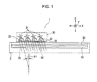
- Fig. 1 is an explanatory view of the hologram recording device and the hologram recording method according to an example of the present invention.
- Figs. 2 and 3 are enlarged views with respect to the method for recording the hologram on the recording medium.
- a hologram recording device 1 shown in Fig. 1 includes a mount table 2 as a mount portion, on which a master recording body 10 and a recording medium 20 are stacked.
- the master recording body 10 may be fixed onto the mount table 2, or structured to be replaceable.
- the recording medium 20 is set in the hologram recording device 1 so as to have the data stored in the master recording body 10 copied (transferred) thereto. That is, the recording medium 20 in the blank state is set in the hologram recording device 1.
- the recording medium 20 having all the data stored in the master recording body 10 recorded is removed from the hologram recording device 1.
- the aforementioned operations may be conducted repeatedly.
- a head 30 is disposed opposite the mount table 2.
- Plural light sources 31 are provided inside the head 30.
- Each of the light sources 31 is equipped with at least one semiconductor laser.
- a VCSEL surface emitting laser
- a VCSEL surface emitting laser
- each wavelength of the plural VCSEL becomes different such that the laser with different wavelength may be emitted from the light source 31 in a predetermined band.
- Collimator lenses 32 are provided opposite the respective light sources 31.
- the laser diffusion light emitted from the light source 31 transmits the corresponding collimator lens 32 and is formed into a reference beam 35 as a parallel luminous flux.
- the head 30 is provided with an optical axis angle variable unit 33 for varying the angle at which the reference beam 35 is irradiated to the recording medium 20.
- the optical axis angle variable unit 33 is formed by combining plural HPDLC (Holographic Polymer Dispersed Liquid Crystal) as one of diffraction gratings. Each of the HPDLCs has a different diffraction angle.
- the respective HPDLCs are selectively driven to change an incident angle ⁇ 1 of the optical axis of the reference beam 35 relative to the recording medium 20 and the master recording body 10.
- the optical axis angle variable unit 33 may be combined with a drive mechanism for varying the position angles of the respective light sources 31 and the collimator lenses 32, or a drive mechanism for varying the position angle of only the collimator lens 32 to change the incident angle ⁇ 1 of the optical axis of the reference beam 35.
- the head 30 shown in Fig. 1 is structured to apply the reference beams 35 as plural parallel luminous fluxes which have passed the optical axis angle variable unit 33 to the recording medium 20 and the master recording body 10.
- the plural reference beams 35 are irradiated only to a part of the recording area of the master recording body 10. Accordingly, in the hologram recording device 1 shown in Fig. 1 , the head 30 is guided moveably in the X and Y directions along a surface of the recording medium 20 while being apart therefrom by a predetermined distance.
- a stepping mechanism for feeding the head 30 stepwise towards the X and Y directions is provided.
- Fig. 2 is an enlarged view which represents the hologram recording method according to Example 1 using the hologram recording device 1 shown in Fig. 1 .
- plural data storage sections 11a, 11b, 11c, 11d,... are formed in the master recording body 10.
- the data storage section 11 is formed by stacking portions each with a different refraction index as an interference fringe in the thickness direction.
- the plural data are overwritten by an angular multiplexing as the page data in the respective data storage sections 11a, 11b, 11c, 11d,....
- the reference beam for recording with a predetermined wavelength ⁇ is applied to the master recording body 10 which contains the photosensitive material from one side, and an object beam which contains data of "1(bright)" and "0(dark)" is applied to the master recording body 10 from the other side.
- the reference beam for recording and the object light are subjected to the interference in the master recording body 10 to bring the regions each with the different refraction index into the interference fringe state.
- the recording medium 20 having no data recorded thereon is placed on the master recording body 10.
- the reference beams 35 formed into the parallel luminous fluxes by the collimator lenses 32 are applied to both the recording medium 20 and the master recording body 10.
- the plural page data are stored in the respective data storage sections 11a, 11b 11c, 11d,... of the master recording body 10 by the angular multiplexing.
- the incident reference beam 35 is diffracted by the interference fringe of the page data stored in any of the data storage sections 11a, 11b, 11c, 11d, ... such that diffracted beams 36 are output each at the angle of ⁇ 2.
- the diffracted beam 36 reflects the data of "1","0" of the page data stored in any of the data storage sections 11a, 11b, 11c, 11d,....
- the diffracted beam 36 based on the Bragg diffraction condition may have the greater intensity upon irradiation of the light with the same wavelength as that of the reference beam at the same incident angle of the reference beam during the recording. Under the Bragg diffraction condition, the incident angle ⁇ 1 of the reference beam 35 is equal to the output angle ⁇ 2 of the diffracted beam 36.
- the optical axis of the reference beam 35 in the head 30, which has passed the collimator lens 32 into the parallel luminous flux is bent by the interference of the optical axis angle variable unit 33 to vary the incident angle ⁇ 1 to the master recording body 10 so as to obtain the diffracted beam 36 from the page data recorded at different incident angles of the reference beams during the recording, that is, stored by the angular multiplexing.
- the reference beam 35 When the reference beam 35 is applied at the predetermined incident angle ⁇ 1 to obtain the diffracted beam 36 having the page data from any of the data storage sections 11a, 11b, 11c, 11d,... of the master recording body 10 reflected, the interference between the diffracted beams 36 and the reference beams 35 occurs in the recording medium 20.
- the page data having the interference fringes each with the different refraction index superimposed are stored in the data storage sections 21a, 21b, 21c, 21d,... of the recording medium 20.
- the incident angle ⁇ 1 of the reference beam 35 is changed to store the plural page data in the data storage sections 21a, 21b, 21c, 21d,... by the angular multiplexing.
- the respective page data stored in the data storage sections 21a, 21b, 21c, 21d,... of the recording medium 20 correspond to the holograms having the same contents as those of the page data stored in the data storage sections 11a, 11b, 11c, 11d,... transferred.
- the blank recording medium 20 is set in the hologram recording device 1, and each of the light sources 31 in the head 30 is illuminated.
- the incident angle ⁇ 1 of the reference beam 35 is changed by the optical axis angle variable unit 33 to transfer the data stored in the respective data storage sections 11a, 11b, 11c, 11d,... to the recording medium 20.
- the plural reference beams 35 from the head 30 are irradiated to the limited area in the range of the data storage sections of the master recording body 10.
- the head is moved toward the X-Y direction after the recording operation with the head 30 to conduct the same recording operation so as to transfer the data stored in all the data storage sections of the master recording body 10 to the recording medium 20.
- a large number of the light sources 31 and the collimator lenses 32 may be provided so as to cover the entire area in the region where the data storage sections of the master recording body 10 are formed.
- the recording medium 20 having the data transferred is removed from the hologram recording device 1, and the new blank recording medium 20 is set to be used for the recording operation.
- the reference beam 35 and the diffracted beam 36 output at the output angle ⁇ 2 which is the same as the incident angle ⁇ 1 intersect inside the recording medium 20 to cause the interference between the diffracted beam 36 and the reference beam 35 therein for the purpose of transferring the page data stored in the data storage sections 11a, 11b, 11c, 11d,... by the angular multiplexing to the recording medium 20 as shown in Fig. 2 .
- the plural light sources 31 are provided in the head 30, and the lights emitted from the respective light sources 31 are irradiated as the plural reference beams 35 in the form of the luminous fluxes.
- a shaded portion 37 is formed between the adjacent reference beams 35. The shaded portion 37 prevents formation of the interference fringe in the recording medium 20.
- the data storage section at the region designated as 11A cannot be transferred to the recording medium 20. It is preferable not to form the data storage section on the region 11A in the master recording body 10.
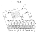
- Fig. 3 is an explanatory view of a hologram recording device 101 according to Example 2, and a hologram recording method using the hologram recording device 101.
- plural data storage sections 11e, 11f, 11g, 11h, 11i, 11j, 11k, 11m, 11n,... are provided at predetermined pitches with no intermittent portion inside the master recording body 10.
- the reference beams 35 emitted from the light source 31 and formed into the parallel luminous fluxes through the collimator lenses 32 are arranged at intervals 38 each having the same length as the diameter of the luminous flux.
- the interval 38 between the adjacent reference beams 35 becomes the shaded portion which prevents transfer of the data stored in the data storage sections 11g and 11n to the recording medium 20. Then as shown in Fig.
- the reference beams 35, 35 are irradiated at the angle changed from the incident angle ⁇ 1 of the reference beam 35 such that the page data stored in the data storage sections 11e, 11f, 11k, and 11m by the angular multiplexing are transferred to the recording medium 20, and the head 30 is moved by ⁇ L.
- the region to which the reference beams 35, 35 are irradiated is moved by the ⁇ L which accords with the pitch of the data storage sections 11e, 11f,... .
- Each incident angle ⁇ 1 of the reference beams 35, 35 is changed while moving the head 30 by the ⁇ L to transfer the data stored in the data storage sections 11f, 11g, 11m, and 11n by the angular multiplexing to the recording medium 20.
- the aforementioned movement by the distance ⁇ L is repeated three times to allow the data stored in all the data storage sections 11e, 11f, 11g, 11h, 11i, 11j, 11k, 11m, 11n,... of the master recording body 10 to be transferred to the recording medium 20.
- the data stored in the data storage section 11f may be written into the data storage section 21f of the recording medium 20 plural times. Accordingly, it is preferable to use the material which allows repetitive overwriting as the photosensitive material contained in the recording medium 20.
- the head may be moved by the distance of 2 x ⁇ L for conducting the recording operation.
- the single light source 31 has a compact structure to apply the reference beams 35 to at least one position of the large number of data storage sections rather than irradiating the reference beams to all the data storage sections of the master recording body 10 simultaneously. Accordingly, the semiconductor laser may be used as the light source 31, which allows the head 30 to be compact, and reduces power consumption.
Landscapes
- Physics & Mathematics (AREA)
- Optics & Photonics (AREA)
- Engineering & Computer Science (AREA)
- Manufacturing & Machinery (AREA)
- General Physics & Mathematics (AREA)
- Holo Graphy (AREA)
- Optical Recording Or Reproduction (AREA)
- Optical Head (AREA)
Abstract
The hologram recording device and the hologram recording method for recording the data stored in the master recording body on the recording medium in the form of the hologram allow the use of the compact light source and reduce the power consumption. A recording medium 20 is stacked on a master recording body 10, to which reference beams 35 are applied each at an incident angle of θ1. The interference between diffracted beams 36 diffracted in the data storage sections 11a, 11b,... of the master recording body 10 and the reference beams 35 in the recording medium 20 occurs such that the data are transferred to the recording medium 20. The use of plural compact light sources for emitting the reference beams 35 allows the recording device to be compact while reducing the power consumption.
Description
- The present invention relates to a hologram recording method and a hologram recording device for recording a hologram on a recording medium which contains a photosensitive material based on the data stored in a data storage section of a master recording body.
- Generally, the method for copying the data stored in the master recording body to the recording medium disclosed in
Patent Document 1 is well known as the method for recording data on the recording medium in the form of the hologram. - With the aforementioned method, the recording medium intended to record the hologram is stacked on the master recording body such that the reference beam is applied to both the master recording body and the recording medium. The reference beam is diffracted in the data storage section inside the master recording body, and the diffracted beam is applied to the recording medium. Inside the recording medium, interference occurs between the diffracted beam and the reference beam. The resultant interference fringe is recorded on the recording medium as the hologram.
Patent Document 1: Japanese Unexamined Patent Application Publication No.2006-18864 - As disclosed in
Patent Document 1, the single reference beam is applied to substantially entire areas of the master recording body and the recording medium such that the hologram is recorded in the recording medium. The aforementioned structure for applying the single reference beam to substantially entire areas of the master recording body and the recording medium requires sufficient optical energy to be supplied to the respective data storage sections recorded on the master recording body. As a result, the use of a large-sized laser emitter with high output such as Ar laser and YAG laser is required as the light source for emitting the reference beam as described above. - The power needed for the hologram recording device may be increased, thus making it difficult to form the simple recording device which allows easy copy of the data recorded in the master recording body to the recording medium at lower costs.
- The present invention provides a hologram recording method and a hologram recording device capable of recording the hologram data on the recording medium while keeping low power consumption.
- The present invention provides a hologram recording method having a recording medium which contains a photosensitive material stacked on a master recording body with a data storage section for generating diffracted beam therein, in which reference beams are irradiated to both the master recording body and the recording medium each at a predetermined incident angle, and the diffracted beams diffracted in the data storage section of the master recording body and the reference beams are subjected to an interference inside the recording medium to record a hologram in the recording medium. Plural light sources are provided for emitting the reference beams so as to be irradiated to a part of the plurality of data storage sections stored in the master recording body.
- In the hologram recording method according to the present invention, each reference beam emitted from plural light sources is irradiated to the data storage section as a part of the master recording body. The use of the plural light sources allows the reference beam emission section to be simply structured, and the power consumption to be reduced without lowering the reference beam power. For example, the light source may be formed of the semiconductor laser.
- In the present invention, each of the reference beams has a different incident angle to the master recording body and the recording medium. The hologram corresponding to the data page stored in the data storage sections of the master recording body by an angular multiplexing may be recorded on the recording medium.
- In the present invention, preferably, a relative position of the light source with respect to the master recording body and the recording medium is changed to move irradiation positions of the reference beams to the master recording body and the recording medium, respectively.
- As described above, the reference beam irradiation positions emitted from the respective light sources are moved to allow the hologram to be recorded on the recording medium based on the data stored over a wide range inside the master recording body. The number of the light sources for the widely ranged data storage may be reduced to allow the recording device to be compact and inexpensive.
- The present invention provides a hologram recording device which includes a mount portion on which a master recording body provided with a data storage section for generating a diffracted light therein and a recording medium which contains a photosensitive material are stacked, and plural light sources to emit the reference beams each irradiated to both the master recording body and the recording medium at a predetermined incident angle. The reference beams are irradiated to a part of the plurality of the data storage sections stored in the master recording body, and the interference between the diffracted beam diffracted in the data storage section and the reference beam occurs in the recording medium to have the hologram recorded in the recording medium.
- For example, the hologram recording device according to the present invention is provided with plural collimator lenses for forming light rays emitted from the respective light sources into reference beams as parallel luminous fluxes, and an optical axis angle variable device for changing each incident angle of the reference beams to the master recording body and the recording medium by changing each angle of the reference beams which have transmitted the respective collimator lenses.
- The hologram recording device according to the present invention allows the use of the semiconductor laser as each of the respective light sources.
- The device according to the present invention may be provided with a relative movement unit for moving an irradiation position of the reference beam to the master recording body and the recording medium by changing a relative position of the light source with respect to the master recording body and the recording medium on the mount portion.
- With the hologram recording method and the hologram recording device according to the present invention, the plural compact light sources are used to apply the reference beams to both the master recording body and the recording medium to realize the thin and compact structure of the device while proposing the power consumption.
-
-
Fig. 1 is an explanatory view of a hologram recording device according to an example of the present invention. -
Fig. 2 is an explanatory view of a hologram recording method according to Example 1. -
Fig. 3 is an explanatory view of a hologram recording method according to Example 2. -
- 1,101
- hologram recording device
- 2
- mount portion
- 10
- master recording body
- 11
- data storage section
- 20
- recording medium
- 21
- data storage section
- 30
- head
- 31
- light source
- 32
- collimator lens
- 33
- optical axis angle variable unit
- 35
- reference beam
-
Fig. 1 is an explanatory view of the hologram recording device and the hologram recording method according to an example of the present invention.Figs. 2 and3 are enlarged views with respect to the method for recording the hologram on the recording medium. - A
hologram recording device 1 shown inFig. 1 includes a mount table 2 as a mount portion, on which amaster recording body 10 and arecording medium 20 are stacked. Themaster recording body 10 may be fixed onto the mount table 2, or structured to be replaceable. Therecording medium 20 is set in thehologram recording device 1 so as to have the data stored in themaster recording body 10 copied (transferred) thereto. That is, therecording medium 20 in the blank state is set in thehologram recording device 1. Therecording medium 20 having all the data stored in themaster recording body 10 recorded is removed from thehologram recording device 1. The aforementioned operations may be conducted repeatedly. - A
head 30 is disposed opposite the mount table 2. Plurallight sources 31 are provided inside thehead 30. Each of thelight sources 31 is equipped with at least one semiconductor laser. A VCSEL (surface emitting laser) is employed as the semiconductor laser. In the case where plural VCSELs are provided in each of thelight sources 31, each wavelength of the plural VCSEL becomes different such that the laser with different wavelength may be emitted from thelight source 31 in a predetermined band. -
Collimator lenses 32 are provided opposite the respectivelight sources 31. The laser diffusion light emitted from thelight source 31 transmits the correspondingcollimator lens 32 and is formed into areference beam 35 as a parallel luminous flux. Thehead 30 is provided with an optical axis anglevariable unit 33 for varying the angle at which thereference beam 35 is irradiated to therecording medium 20. The optical axis anglevariable unit 33 is formed by combining plural HPDLC (Holographic Polymer Dispersed Liquid Crystal) as one of diffraction gratings. Each of the HPDLCs has a different diffraction angle. The respective HPDLCs are selectively driven to change an incident angle θ1 of the optical axis of thereference beam 35 relative to therecording medium 20 and themaster recording body 10. - The optical axis angle
variable unit 33 may be combined with a drive mechanism for varying the position angles of the respectivelight sources 31 and thecollimator lenses 32, or a drive mechanism for varying the position angle of only thecollimator lens 32 to change the incident angle θ1 of the optical axis of thereference beam 35. - The
head 30 shown inFig. 1 is structured to apply the reference beams 35 as plural parallel luminous fluxes which have passed the optical axis anglevariable unit 33 to therecording medium 20 and themaster recording body 10. However, the plural reference beams 35 are irradiated only to a part of the recording area of themaster recording body 10. Accordingly, in thehologram recording device 1 shown inFig. 1 , thehead 30 is guided moveably in the X and Y directions along a surface of therecording medium 20 while being apart therefrom by a predetermined distance. A stepping mechanism for feeding thehead 30 stepwise towards the X and Y directions is provided. -
Fig. 2 is an enlarged view which represents the hologram recording method according to Example 1 using thehologram recording device 1 shown inFig. 1 . - Referring to
Fig. 2 , pluraldata storage sections master recording body 10. The data storage section 11 is formed by stacking portions each with a different refraction index as an interference fringe in the thickness direction. The plural data are overwritten by an angular multiplexing as the page data in the respectivedata storage sections master recording body 10 which contains the photosensitive material from one side, and an object beam which contains data of "1(bright)" and "0(dark)" is applied to themaster recording body 10 from the other side. The reference beam for recording and the object light are subjected to the interference in themaster recording body 10 to bring the regions each with the different refraction index into the interference fringe state. - Referring to
Fig. 2 , therecording medium 20 having no data recorded thereon is placed on themaster recording body 10. The reference beams 35 formed into the parallel luminous fluxes by thecollimator lenses 32 are applied to both therecording medium 20 and themaster recording body 10. The plural page data are stored in the respectivedata storage sections 11b master recording body 10 by the angular multiplexing. Upon incidence of thereference beam 35 to themaster recording body 10 at the angle of θ1, theincident reference beam 35 is diffracted by the interference fringe of the page data stored in any of thedata storage sections - The diffracted
beam 36 reflects the data of "1","0" of the page data stored in any of thedata storage sections beam 36 based on the Bragg diffraction condition may have the greater intensity upon irradiation of the light with the same wavelength as that of the reference beam at the same incident angle of the reference beam during the recording. Under the Bragg diffraction condition, the incident angle θ1 of thereference beam 35 is equal to the output angle θ2 of the diffractedbeam 36. The optical axis of thereference beam 35 in thehead 30, which has passed thecollimator lens 32 into the parallel luminous flux is bent by the interference of the optical axis anglevariable unit 33 to vary the incident angle θ1 to themaster recording body 10 so as to obtain the diffractedbeam 36 from the page data recorded at different incident angles of the reference beams during the recording, that is, stored by the angular multiplexing. - When the
reference beam 35 is applied at the predetermined incident angle θ1 to obtain the diffractedbeam 36 having the page data from any of thedata storage sections master recording body 10 reflected, the interference between the diffractedbeams 36 and the reference beams 35 occurs in therecording medium 20. The page data having the interference fringes each with the different refraction index superimposed are stored in thedata storage sections recording medium 20. As the incident angle θ1 of thereference beam 35 is changed to store the plural page data in thedata storage sections data storage sections recording medium 20 correspond to the holograms having the same contents as those of the page data stored in thedata storage sections - The
blank recording medium 20 is set in thehologram recording device 1, and each of thelight sources 31 in thehead 30 is illuminated. The incident angle θ1 of thereference beam 35 is changed by the optical axis anglevariable unit 33 to transfer the data stored in the respectivedata storage sections recording medium 20. - With the
hologram recording device 1 shown inFig. 1 , the plural reference beams 35 from thehead 30 are irradiated to the limited area in the range of the data storage sections of themaster recording body 10. The head is moved toward the X-Y direction after the recording operation with thehead 30 to conduct the same recording operation so as to transfer the data stored in all the data storage sections of themaster recording body 10 to therecording medium 20. A large number of thelight sources 31 and thecollimator lenses 32 may be provided so as to cover the entire area in the region where the data storage sections of themaster recording body 10 are formed. - The
recording medium 20 having the data transferred is removed from thehologram recording device 1, and the newblank recording medium 20 is set to be used for the recording operation. - Referring to
Fig. 2 , thereference beam 35 and the diffractedbeam 36 output at the output angle θ2 which is the same as the incident angle θ1 intersect inside therecording medium 20 to cause the interference between the diffractedbeam 36 and thereference beam 35 therein for the purpose of transferring the page data stored in thedata storage sections recording medium 20 as shown inFig. 2 . - In the
hologram recording device 1 according to the example, the plurallight sources 31 are provided in thehead 30, and the lights emitted from the respectivelight sources 31 are irradiated as the plural reference beams 35 in the form of the luminous fluxes. Referring toFig. 2 , a shadedportion 37 is formed between the adjacent reference beams 35. The shadedportion 37 prevents formation of the interference fringe in therecording medium 20. The data storage section at the region designated as 11A cannot be transferred to therecording medium 20. It is preferable not to form the data storage section on theregion 11A in themaster recording body 10. -
Fig. 3 is an explanatory view of ahologram recording device 101 according to Example 2, and a hologram recording method using thehologram recording device 101. - In the
hologram recording device 101, pluraldata storage sections master recording body 10. - The reference beams 35 emitted from the
light source 31 and formed into the parallel luminous fluxes through thecollimator lenses 32 are arranged atintervals 38 each having the same length as the diameter of the luminous flux. When thelight source 31 is illuminated to irradiate thereference beam 35, theinterval 38 between the adjacent reference beams 35 becomes the shaded portion which prevents transfer of the data stored in thedata storage sections recording medium 20. Then as shown inFig. 3 , the reference beams 35, 35 are irradiated at the angle changed from the incident angle θ1 of thereference beam 35 such that the page data stored in thedata storage sections recording medium 20, and thehead 30 is moved by ΔL. As a result, the region to which the reference beams 35, 35 are irradiated is moved by the ΔL which accords with the pitch of thedata storage sections - Each incident angle θ1 of the reference beams 35, 35 is changed while moving the
head 30 by the ΔL to transfer the data stored in thedata storage sections recording medium 20. The aforementioned movement by the distance ΔL is repeated three times to allow the data stored in all thedata storage sections master recording body 10 to be transferred to therecording medium 20. - With the aforementioned recording method, the data stored in the
data storage section 11f may be written into thedata storage section 21f of therecording medium 20 plural times. Accordingly, it is preferable to use the material which allows repetitive overwriting as the photosensitive material contained in therecording medium 20. The head may be moved by the distance of 2 x ΔL for conducting the recording operation. - In the hologram recording device and the hologram recording method according to the aforementioned examples, the single
light source 31 has a compact structure to apply the reference beams 35 to at least one position of the large number of data storage sections rather than irradiating the reference beams to all the data storage sections of themaster recording body 10 simultaneously. Accordingly, the semiconductor laser may be used as thelight source 31, which allows thehead 30 to be compact, and reduces power consumption.
Claims (8)
- A hologram recording method having a recording medium which contains a photosensitive material stacked on a master recording body with a data storage section for generating a diffracted beam therein, in which reference beams are irradiated to both the master recording body and the recording medium each at a predetermined incident angle, and the diffracted beams diffracted in the data storage section of the master recording body and the reference beams are subjected to an interference inside the recording medium to record a hologram on the recording medium, wherein a plurality of light sources are provided for emitting the reference beams to be irradiated to a part of the plurality of data storage sections stored in the master recording body.
- The hologram recording method according to Claim 1, wherein the light source is a semiconductor laser.
- The hologram recording method according to Claim 1 or 2, wherein:each of the reference beams has a different incident angle to the master recording body and the recording medium; andthe hologram corresponding to the data page stored in the data storage sections of the master recording body by an angular multiplexing is recorded on the recording medium.
- The hologram recording method according to any one of Claims 1 to 3, wherein a relative position of the light source with respect to the master recording body and the recording medium is changed to move irradiation positions of the reference beams to the master recording body and the recording medium, respectively.
- A hologram recording device comprising:a mount portion on which a master recording body provided with a data storage section for generating a diffracted light therein and a recording medium which contains a photosensitive material are stacked; andplural light sources for emitting the reference beams each irradiated to both the master recording body and the recording medium at a predetermined incident angle, wherein the reference beams are irradiated to a part of the plurality of the data storage sections stored in the master recording body, and the interference between the diffracted beam diffracted in the data storage section and the reference beam occurs in the recording medium to have the hologram recorded on the recording medium.
- The hologram recording device according to Claim 5, further comprising a plurality of collimator lenses for forming light rays emitted from the respective light sources into reference beams as parallel luminous fluxes, and an optical axis angle variable device for changing each incident angle of the reference beams to the master recording body and the recording medium by changing each angle of the reference beams which have transmitted the respective collimator lenses.
- The hologram recording device according to Claim 5 or 6, wherein each of the respective light sources is a semiconductor laser.
- The hologram recording device according to any one of claims 5 to 7, further comprising a relative movement unit for moving an irradiation position of the reference beam to the master recording body and the recording medium by changing a relative position of the light source with respect to the master recording body and the recording medium on the mount portion.
Applications Claiming Priority (2)
| Application Number | Priority Date | Filing Date | Title |
|---|---|---|---|
| JP2006236452 | 2006-08-31 | ||
| PCT/JP2007/066760 WO2008026637A1 (en) | 2006-08-31 | 2007-08-29 | Hologram recording method and hologram recording device |
Publications (1)
| Publication Number | Publication Date |
|---|---|
| EP2068209A1 true EP2068209A1 (en) | 2009-06-10 |
Family
ID=39135919
Family Applications (1)
| Application Number | Title | Priority Date | Filing Date |
|---|---|---|---|
| EP07806237A Withdrawn EP2068209A1 (en) | 2006-08-31 | 2007-08-29 | Hologram recording method and hologram recording device |
Country Status (4)
| Country | Link |
|---|---|
| US (1) | US20090168130A1 (en) |
| EP (1) | EP2068209A1 (en) |
| JP (1) | JPWO2008026637A1 (en) |
| WO (1) | WO2008026637A1 (en) |
Cited By (1)
| Publication number | Priority date | Publication date | Assignee | Title |
|---|---|---|---|---|
| US11679616B2 (en) | 2017-09-06 | 2023-06-20 | Ovd Kinegram Ag | Method for producing a hologram, and security element and a security document |
Families Citing this family (3)
| Publication number | Priority date | Publication date | Assignee | Title |
|---|---|---|---|---|
| JP2011022330A (en) * | 2009-07-15 | 2011-02-03 | Fuji Xerox Co Ltd | Exposure device, image forming device, and hologram recording device |
| KR102501363B1 (en) * | 2020-10-08 | 2023-02-21 | 주식회사 홀로랩 | Hologram replication method and system based on mirror movement |
| KR102680801B1 (en) * | 2021-06-29 | 2024-07-03 | 주식회사 홀로랩 | Holographic close replication system |
Family Cites Families (2)
| Publication number | Priority date | Publication date | Assignee | Title |
|---|---|---|---|---|
| JP2005331864A (en) * | 2004-05-21 | 2005-12-02 | Alps Electric Co Ltd | Hologram apparatus |
| JP2006018864A (en) | 2004-06-30 | 2006-01-19 | Sony Corp | Hologram replication method |
-
2007
- 2007-08-29 EP EP07806237A patent/EP2068209A1/en not_active Withdrawn
- 2007-08-29 WO PCT/JP2007/066760 patent/WO2008026637A1/en not_active Ceased
- 2007-08-29 JP JP2008532091A patent/JPWO2008026637A1/en not_active Withdrawn
-
2009
- 2009-02-27 US US12/395,177 patent/US20090168130A1/en not_active Abandoned
Non-Patent Citations (1)
| Title |
|---|
| See references of WO2008026637A1 * |
Cited By (1)
| Publication number | Priority date | Publication date | Assignee | Title |
|---|---|---|---|---|
| US11679616B2 (en) | 2017-09-06 | 2023-06-20 | Ovd Kinegram Ag | Method for producing a hologram, and security element and a security document |
Also Published As
| Publication number | Publication date |
|---|---|
| US20090168130A1 (en) | 2009-07-02 |
| JPWO2008026637A1 (en) | 2010-01-21 |
| WO2008026637A1 (en) | 2008-03-06 |
Similar Documents
| Publication | Publication Date | Title |
|---|---|---|
| US11868087B2 (en) | Method and device for producing a computer-generated hologram, hologram, and lighting device for a vehicle | |
| US20040257629A1 (en) | Lithograph comprising a moving cylindrical lens system | |
| KR960005483A (en) | Semiconductor laser device and optical pickup device using same | |
| US20090168130A1 (en) | Hologram recording method and hologram recording device | |
| US6320683B1 (en) | Optical information recording and reproducing apparatus using a volume holographic memory | |
| US20050231775A1 (en) | Hologram recording/reproducing method and hologram recording/reproducing device | |
| JP5816046B2 (en) | A method of storing bit-wise holographic data in parallel using a parallel light source | |
| KR20070006686A (en) | Method and apparatus for fixing holographic media in holographic data storage system | |
| US8625184B2 (en) | Optical exposure apparatus and systems | |
| CN116430495A (en) | Exposure method, exposure light path and exposure system of volume holographic optical waveguide grating | |
| KR101075351B1 (en) | Hologram recording device | |
| US7384709B2 (en) | Lithograph with a trigger mask and method of producing digital holograms in a storage medium | |
| US6301028B1 (en) | Holographic memory and optical information recording and reproducing apparatus using the same | |
| JP5201503B2 (en) | Pre-exposure and curing of photosensitive materials for optical data storage | |
| CN111338196B (en) | Method and device for producing a computer-generated hologram, hologram and lighting device for a vehicle | |
| US12546926B2 (en) | Holographic optical element, manufacturing method therefor and manufacturing device therefor | |
| US9278546B2 (en) | Optical writing head and image forming apparatus | |
| JP2803434B2 (en) | Diffraction grating plotter | |
| KR102219835B1 (en) | Method for manufacturing a holographic optical element | |
| CN223180433U (en) | Holographic grating exposure device and holographic grating preparation system | |
| US20090116086A1 (en) | Hologram recording device and hologram recording method | |
| US20080025185A1 (en) | Hologram Reproducing Head | |
| EP2015296B1 (en) | Holographic storage system with integrated phase mask | |
| US20250004422A1 (en) | Holographic Interference Pattern Recording Apparatus and Recording Method Using Same | |
| US7847991B2 (en) | Holographic storage medium |
Legal Events
| Date | Code | Title | Description |
|---|---|---|---|
| PUAI | Public reference made under article 153(3) epc to a published international application that has entered the european phase |
Free format text: ORIGINAL CODE: 0009012 |
|
| 17P | Request for examination filed |
Effective date: 20090312 |
|
| AK | Designated contracting states |
Kind code of ref document: A1 Designated state(s): AT BE BG CH CY CZ DE DK EE ES FI FR GB GR HU IE IS IT LI LT LU LV MC MT NL PL PT RO SE SI SK TR |
|
| AX | Request for extension of the european patent |
Extension state: AL BA HR MK RS |
|
| DAX | Request for extension of the european patent (deleted) | ||
| RBV | Designated contracting states (corrected) |
Designated state(s): DE FR GB |
|
| STAA | Information on the status of an ep patent application or granted ep patent |
Free format text: STATUS: THE APPLICATION HAS BEEN WITHDRAWN |
|
| 18W | Application withdrawn |
Effective date: 20091203 |