EP2068174A2 - Ultrasound system and method of forming an ultrasound image - Google Patents
Ultrasound system and method of forming an ultrasound image Download PDFInfo
- Publication number
- EP2068174A2 EP2068174A2 EP08021153A EP08021153A EP2068174A2 EP 2068174 A2 EP2068174 A2 EP 2068174A2 EP 08021153 A EP08021153 A EP 08021153A EP 08021153 A EP08021153 A EP 08021153A EP 2068174 A2 EP2068174 A2 EP 2068174A2
- Authority
- EP
- European Patent Office
- Prior art keywords
- ultrasound
- dimensional
- image
- sample volume
- moving
- Prior art date
- Legal status (The legal status is an assumption and is not a legal conclusion. Google has not performed a legal analysis and makes no representation as to the accuracy of the status listed.)
- Ceased
Links
Images


Classifications
-
- G—PHYSICS
- G01—MEASURING; TESTING
- G01S—RADIO DIRECTION-FINDING; RADIO NAVIGATION; DETERMINING DISTANCE OR VELOCITY BY USE OF RADIO WAVES; LOCATING OR PRESENCE-DETECTING BY USE OF THE REFLECTION OR RERADIATION OF RADIO WAVES; ANALOGOUS ARRANGEMENTS USING OTHER WAVES
- G01S15/00—Systems using the reflection or reradiation of acoustic waves, e.g. sonar systems
- G01S15/88—Sonar systems specially adapted for specific applications
- G01S15/89—Sonar systems specially adapted for specific applications for mapping or imaging
- G01S15/8906—Short-range imaging systems; Acoustic microscope systems using pulse-echo techniques
- G01S15/8993—Three dimensional imaging systems
-
- G—PHYSICS
- G01—MEASURING; TESTING
- G01S—RADIO DIRECTION-FINDING; RADIO NAVIGATION; DETERMINING DISTANCE OR VELOCITY BY USE OF RADIO WAVES; LOCATING OR PRESENCE-DETECTING BY USE OF THE REFLECTION OR RERADIATION OF RADIO WAVES; ANALOGOUS ARRANGEMENTS USING OTHER WAVES
- G01S7/00—Details of systems according to groups G01S13/00, G01S15/00, G01S17/00
- G01S7/52—Details of systems according to groups G01S13/00, G01S15/00, G01S17/00 of systems according to group G01S15/00
- G01S7/52017—Details of systems according to groups G01S13/00, G01S15/00, G01S17/00 of systems according to group G01S15/00 particularly adapted to short-range imaging
- G01S7/52053—Display arrangements
- G01S7/52057—Cathode ray tube displays
- G01S7/5206—Two-dimensional coordinated display of distance and direction; B-scan display
- G01S7/52063—Sector scan display
-
- G—PHYSICS
- G01—MEASURING; TESTING
- G01S—RADIO DIRECTION-FINDING; RADIO NAVIGATION; DETERMINING DISTANCE OR VELOCITY BY USE OF RADIO WAVES; LOCATING OR PRESENCE-DETECTING BY USE OF THE REFLECTION OR RERADIATION OF RADIO WAVES; ANALOGOUS ARRANGEMENTS USING OTHER WAVES
- G01S7/00—Details of systems according to groups G01S13/00, G01S15/00, G01S17/00
- G01S7/52—Details of systems according to groups G01S13/00, G01S15/00, G01S17/00 of systems according to group G01S15/00
- G01S7/52017—Details of systems according to groups G01S13/00, G01S15/00, G01S17/00 of systems according to group G01S15/00 particularly adapted to short-range imaging
- G01S7/52053—Display arrangements
- G01S7/52057—Cathode ray tube displays
- G01S7/5206—Two-dimensional coordinated display of distance and direction; B-scan display
- G01S7/52066—Time-position or time-motion displays
-
- G—PHYSICS
- G01—MEASURING; TESTING
- G01S—RADIO DIRECTION-FINDING; RADIO NAVIGATION; DETERMINING DISTANCE OR VELOCITY BY USE OF RADIO WAVES; LOCATING OR PRESENCE-DETECTING BY USE OF THE REFLECTION OR RERADIATION OF RADIO WAVES; ANALOGOUS ARRANGEMENTS USING OTHER WAVES
- G01S15/00—Systems using the reflection or reradiation of acoustic waves, e.g. sonar systems
- G01S15/88—Sonar systems specially adapted for specific applications
- G01S15/89—Sonar systems specially adapted for specific applications for mapping or imaging
- G01S15/8906—Short-range imaging systems; Acoustic microscope systems using pulse-echo techniques
- G01S15/8979—Combined Doppler and pulse-echo imaging systems
-
- G—PHYSICS
- G01—MEASURING; TESTING
- G01S—RADIO DIRECTION-FINDING; RADIO NAVIGATION; DETERMINING DISTANCE OR VELOCITY BY USE OF RADIO WAVES; LOCATING OR PRESENCE-DETECTING BY USE OF THE REFLECTION OR RERADIATION OF RADIO WAVES; ANALOGOUS ARRANGEMENTS USING OTHER WAVES
- G01S7/00—Details of systems according to groups G01S13/00, G01S15/00, G01S17/00
- G01S7/52—Details of systems according to groups G01S13/00, G01S15/00, G01S17/00 of systems according to group G01S15/00
- G01S7/52017—Details of systems according to groups G01S13/00, G01S15/00, G01S17/00 of systems according to group G01S15/00 particularly adapted to short-range imaging
- G01S7/52053—Display arrangements
- G01S7/52057—Cathode ray tube displays
- G01S7/52074—Composite displays, e.g. split-screen displays; Combination of multiple images or of images and alphanumeric tabular information
Definitions
- the present invention generally relates to ultrasound systems, and more particularly to an ultrasound system and a method of forming an ultrasound image.
- An ultrasound system has become an important and popular diagnostic tool since it has a wide range of applications. Specifically, due to its non-invasive and nondestructive nature, the ultrasound has been extensively used in the medical profession. Modem high-performance ultrasound diagnostic systems and techniques are commonly used to produce two or three-dimensional diagnostic images of internal features of an object (e.g., human organs).
- an object e.g., human organs
- the ultrasound system may provide a Doppler mode (D mode) for indicating a motion velocity of a moving object such as red blood cells in a blood vessel, cardiac valves and the like as a spectral Doppler image by using a Doppler shift.
- D mode Doppler mode
- a sample volume needs to be previously set on a brightness mode (B mode) image and Doppler signals corresponding to the sample volume are then obtained.
- B mode brightness mode
- the ultrasound system may form and output the Doppler spectral image based on the Doppler signals.
- the B-mode image is a 2-dimensional image of a grey scale, it may be difficult for the user to set the sample volume on a desirable vessel or a cardiac valve on the B-mode image. Thus, an accurate spectral Doppler image may not be provided.
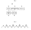
- FIG. 1 is a block diagram showing an illustrative embodiment of an ultrasound system.
- FIG. 2 is a timing diagram showing transmission and reception of first and second ultrasound beams.
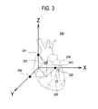
- FIG. 3 is a schematic diagram showing an example of displaying a 3-dimensional ultrasound image, sample volumes and 3-dimensional coordinates.
- FIGS. 4 to 6 are schematic diagrams showing examples of displaying a 3-dimensional ultrasound image together with spectral Doppler images.
- FIG. 1 is a block diagram illustrating one embodiment of an ultrasound system.
- the ultrasound system 100 may include an input unit 110 for receiving user instructions.
- the user instructions may include a setup instruction for setting the number, size and position of sample volumes, a selection instruction for selecting at least one of the sample volumes, and a moving instruction for moving the sample volume.
- the sample volume may be formed to have a 3-dimensional figure such as a predefined hexahedron, sphere or the like.
- the ultrasound system 100 may further include a control unit 120, which may be configured to control the transmission/reception of an ultrasound beam according to image modes of the ultrasound system 100.
- the control unit 120 may generate a first control signal for controlling the transmission of a first ultrasound beam for forming a 3-dimensional ultrasound image of a target object.
- the control unit may be configured to generate a second control signal.
- the second control signal may be used to control the transmission of a second ultrasound beam for forming a spectral Doppler image corresponding to a sample volume, which is set on the 3-dimensional ultrasound image of the target object, based on the setup instruction and the moving instruction.
- the control unit 120 may be configured to repeatedly generate the first and second control signals such that the first ultrasound beam 3D and the second ultrasound beams D1, D2 and D3 for obtaining spectral Doppler signals from the sample volumes SV1, SV2 and SV3 are repeatedly performed, as illustrated in FIG. 2 .
- the control unit 120 may control the second ultrasound beams D1, D2 and D3 to be alternately transmitted.
- the control unit 120 may be further configured to generate a third control signal for controlling providing 3-dimensional coordinate information of the selected sample volume selected in response to the selection instruction. Also, the control unit 120 may generate a fourth control signal for controlling moving the selected sample volume in response to the moving instruction.
- the ultrasound system may include a transmission/reception unit 130 configured to transmit the ultrasound beam to a target object under the control of the control unit 120.
- the transmission/reception unit 130 may include a probe (not shown) for generating ultrasound signals in response to electrical pulse signals and vice-versa.
- the probe may be one of a mechanical 3-dimensional probe, a 2-dimensional array probe, a matrix array probe and the like.
- the transmission/reception unit 130 may transmit the first ultrasound beam to the target object in response to the first control signal and convert ultrasound echoes reflected from the target object into electrical receive signals (hereinafter referred to as "first receive signals").
- the transmission/reception unit 130 may transmit the second ultrasound beam to the target object in response to the second control signal and convert the ultrasound echoes reflected from the target object into electrical receive signals (hereinafter referred to as "second receive signals").
- an image processing unit 140 may be configured to form a 3-dimensional image based on the first receive signals and a Spectral Doppler image based on the second receive signals. Also, the image processing unit 140 may provide the 3-dimensional coordinate information of the selected sample volume in response to the third control signals outputted from the control unit 120. In one embodiment, the image processing unit 140 may set 3-dimensional (XYZ) coordinates on a screen, on which the 3-dimensional ultrasound image is displayed, in response to the third control signals. The image processing unit 140 may be configured to display 3-dimensional coordinate information regarding a position of the corresponding sample volume on the 3-dimensional coordinates.
- the 3-dimensional ultrasound image which is used to set the 3-dimensional coordinates, may be a 3-dimensional static image or a real-time 3-dimensional moving image.
- the transmission/reception unit 130 may transmit a diffraction limited beam as the ultrasound transmit beam for forming the real-time 3-dimensional moving image, thereby forming the first receive signals.
- the image processing unit 140 may set 3-dimensional coordinates 240 on a 3-dimensional ultrasound image 210 as illustrated in FIG. 3 .
- the image processing unit 140 may display 3-dimensional coordinate information 241, 242 and 243 of a sample volume 221 selected from three sample volumes 221, 222 and 223, which are set on the 3-dimensional ultrasound image, on the 3-dimensional coordinates 240 with texts and the like in response to the third control signals.
- the image processing unit 140 may display the 3-dimensional coordinate information of the sample volume on the 3-dimensional coordinates in one embodiment, it is certainly not limited thereto.
- the image processing unit 140 may display the 3-dimensional coordinate information of the sample volume as a numerical value.
- the image processing unit 140 may be configured to effect a movement of the sample volume in response to the fourth control signals, followed by displaying 3-dimensional coordinate information of the moved sample volume.
- a display unit 150 may be configured to display the 3-dimensional ultrasound image and the spectral Doppler image, which are processed by the image processing unit 140.
- the display unit 150 may display the 3-dimensional ultrasound image on a first display region 151 assigned at a left side of the screen 151, as illustrated in FIG. 5 .
- the display unit 150 may display first, second and third spectral Doppler images 231, 232 and 233 corresponding to the sample volumes 221, 222 and 223 on second display regions 152, 153 and 154 assigned at a right side of the screen 151.
- the display unit 150 may display the first to third spectral Doppler images 231, 232 and 233 corresponding to the first to third sample volumes 221, 222 and 223 on first display regions 152, 153 and 154 assigned to the entire screen, as illustrated in FIG. 6 .
- the display unit 150 may display the 3-dimensional ultrasound image on a second display region 151 assigned at an arbitrary position on the first display regions.
- the ultrasound system 100 may be controlled such that the 3-dimensional ultrasound image is always displayed over the first to third spectral Doppler images 231, 232 and 233.
- the number of the first display regions may be determined depending on the number of the sample volumes set in the 3-dimensional image.
- At least one sample volume having a 3-dimensional figure may be set on the 3-dimensional ultrasound image and the 3-dimensional coordinate information of the sample volume may be provided. Thus, it may allow the user to move the sample volume to a desirable position.
- an ultrasound system comprising: an image processing unit configured to form at least one 3-dimensional ultrasound image based on ultrasound echoes reflected from a target object; an input unit configured to receive a setup instruction; and a control unit configured to output a first control signal for setting at least one predefined sample volume on the 3-dimensional ultrasound image in response to the setup instruction, wherein the image processing unit is further configured to form at least one spectral Doppler image corresponding to the sample volume in response to the first control signal.
- a method of forming an ultrasound image comprising: transmitting a first ultrasound beam to a target object and receiving ultrasound echoes reflected from the target object to thereby generate first receive signals; forming a 3-dimensional ultrasound image based on the first receive signals; receiving a setup instruction; setting at least one predetermined sample volume on the 3-dimensional ultrasound image in response to the setup instruction; transmitting a second ultrasound beam to a target object and receiving the ultrasound echoes reflected from the target object to thereby generate second receive signals; and forming a spectral Doppler image based on the second receive signals.
- any reference in this specification to "one embodiment,” “an embodiment,” “example embodiment,” etc. means that a particular feature, structure or characteristic described in connection with the embodiment is included in at least one embodiment of the present invention.
- the appearances of such phrases in various places in the specification are not necessarily all referring to the same embodiment.
Landscapes
- Engineering & Computer Science (AREA)
- Physics & Mathematics (AREA)
- Radar, Positioning & Navigation (AREA)
- Remote Sensing (AREA)
- Computer Networks & Wireless Communication (AREA)
- General Physics & Mathematics (AREA)
- Acoustics & Sound (AREA)
- Ultra Sonic Daignosis Equipment (AREA)
Abstract
Description
- The present application claims priority from
Korean Patent Application Nos. 10-2007-0125376 10-2008-0078392 - The present invention generally relates to ultrasound systems, and more particularly to an ultrasound system and a method of forming an ultrasound image.
- An ultrasound system has become an important and popular diagnostic tool since it has a wide range of applications. Specifically, due to its non-invasive and nondestructive nature, the ultrasound has been extensively used in the medical profession. Modem high-performance ultrasound diagnostic systems and techniques are commonly used to produce two or three-dimensional diagnostic images of internal features of an object (e.g., human organs).
- The ultrasound system may provide a Doppler mode (D mode) for indicating a motion velocity of a moving object such as red blood cells in a blood vessel, cardiac valves and the like as a spectral Doppler image by using a Doppler shift. In order to provide the spectral Doppler image, a sample volume needs to be previously set on a brightness mode (B mode) image and Doppler signals corresponding to the sample volume are then obtained. The ultrasound system may form and output the Doppler spectral image based on the Doppler signals.
- However, since the B-mode image is a 2-dimensional image of a grey scale, it may be difficult for the user to set the sample volume on a desirable vessel or a cardiac valve on the B-mode image. Thus, an accurate spectral Doppler image may not be provided.
-
FIG. 1 is a block diagram showing an illustrative embodiment of an ultrasound system. -
FIG. 2 is a timing diagram showing transmission and reception of first and second ultrasound beams. -
FIG. 3 is a schematic diagram showing an example of displaying a 3-dimensional ultrasound image, sample volumes and 3-dimensional coordinates. -
FIGS. 4 to 6 are schematic diagrams showing examples of displaying a 3-dimensional ultrasound image together with spectral Doppler images. -
FIG. 1 is a block diagram illustrating one embodiment of an ultrasound system. Referring toFIG. 1 , theultrasound system 100 may include aninput unit 110 for receiving user instructions. The user instructions may include a setup instruction for setting the number, size and position of sample volumes, a selection instruction for selecting at least one of the sample volumes, and a moving instruction for moving the sample volume. The sample volume may be formed to have a 3-dimensional figure such as a predefined hexahedron, sphere or the like. - The
ultrasound system 100 may further include acontrol unit 120, which may be configured to control the transmission/reception of an ultrasound beam according to image modes of theultrasound system 100. In a 3-dimensional image mode of theultrasound system 100, thecontrol unit 120 may generate a first control signal for controlling the transmission of a first ultrasound beam for forming a 3-dimensional ultrasound image of a target object. Also, the control unit may be configured to generate a second control signal. The second control signal may be used to control the transmission of a second ultrasound beam for forming a spectral Doppler image corresponding to a sample volume, which is set on the 3-dimensional ultrasound image of the target object, based on the setup instruction and the moving instruction. Thecontrol unit 120 may be configured to repeatedly generate the first and second control signals such that thefirst ultrasound beam 3D and the second ultrasound beams D1, D2 and D3 for obtaining spectral Doppler signals from the sample volumes SV1, SV2 and SV3 are repeatedly performed, as illustrated inFIG. 2 . In such a case, thecontrol unit 120 may control the second ultrasound beams D1, D2 and D3 to be alternately transmitted. - The
control unit 120 may be further configured to generate a third control signal for controlling providing 3-dimensional coordinate information of the selected sample volume selected in response to the selection instruction. Also, thecontrol unit 120 may generate a fourth control signal for controlling moving the selected sample volume in response to the moving instruction. - The ultrasound system may include a transmission/
reception unit 130 configured to transmit the ultrasound beam to a target object under the control of thecontrol unit 120. The transmission/reception unit 130 may include a probe (not shown) for generating ultrasound signals in response to electrical pulse signals and vice-versa. The probe may be one of a mechanical 3-dimensional probe, a 2-dimensional array probe, a matrix array probe and the like. The transmission/reception unit 130 may transmit the first ultrasound beam to the target object in response to the first control signal and convert ultrasound echoes reflected from the target object into electrical receive signals (hereinafter referred to as "first receive signals"). The transmission/reception unit 130 may transmit the second ultrasound beam to the target object in response to the second control signal and convert the ultrasound echoes reflected from the target object into electrical receive signals (hereinafter referred to as "second receive signals"). - In connection with the transmission/
reception unit 130, animage processing unit 140 may be configured to form a 3-dimensional image based on the first receive signals and a Spectral Doppler image based on the second receive signals. Also, theimage processing unit 140 may provide the 3-dimensional coordinate information of the selected sample volume in response to the third control signals outputted from thecontrol unit 120. In one embodiment, theimage processing unit 140 may set 3-dimensional (XYZ) coordinates on a screen, on which the 3-dimensional ultrasound image is displayed, in response to the third control signals. Theimage processing unit 140 may be configured to display 3-dimensional coordinate information regarding a position of the corresponding sample volume on the 3-dimensional coordinates. In one embodiment, the 3-dimensional ultrasound image, which is used to set the 3-dimensional coordinates, may be a 3-dimensional static image or a real-time 3-dimensional moving image. The transmission/reception unit 130 may transmit a diffraction limited beam as the ultrasound transmit beam for forming the real-time 3-dimensional moving image, thereby forming the first receive signals. - For example, the
image processing unit 140 may set 3-dimensional coordinates 240 on a 3-dimensional ultrasound image 210 as illustrated inFIG. 3 . Theimage processing unit 140 may display 3-dimensional coordinate information sample volume 221 selected from threesample volumes dimensional coordinates 240 with texts and the like in response to the third control signals. Although it has been described that theimage processing unit 140 may display the 3-dimensional coordinate information of the sample volume on the 3-dimensional coordinates in one embodiment, it is certainly not limited thereto. In another embodiment, theimage processing unit 140 may display the 3-dimensional coordinate information of the sample volume as a numerical value. Theimage processing unit 140 may be configured to effect a movement of the sample volume in response to the fourth control signals, followed by displaying 3-dimensional coordinate information of the moved sample volume. - A
display unit 150 may be configured to display the 3-dimensional ultrasound image and the spectral Doppler image, which are processed by theimage processing unit 140. In one embodiment, thedisplay unit 150 may display the 3-dimensional ultrasound image on afirst display region 151 assigned at a left side of thescreen 151, as illustrated inFIG. 5 . Further, thedisplay unit 150 may display first, second and third spectral Dopplerimages sample volumes second display regions screen 151. - In another embodiment, the
display unit 150 may display the first to third spectral Dopplerimages third sample volumes first display regions FIG. 6 . Thedisplay unit 150 may display the 3-dimensional ultrasound image on asecond display region 151 assigned at an arbitrary position on the first display regions. In such a case, theultrasound system 100 may be controlled such that the 3-dimensional ultrasound image is always displayed over the first to third spectral Dopplerimages - As mentioned above, at least one sample volume having a 3-dimensional figure may be set on the 3-dimensional ultrasound image and the 3-dimensional coordinate information of the sample volume may be provided. Thus, it may allow the user to move the sample volume to a desirable position.
- In accordance with one embodiment of the present invention, there is provided an ultrasound system, comprising: an image processing unit configured to form at least one 3-dimensional ultrasound image based on ultrasound echoes reflected from a target object; an input unit configured to receive a setup instruction; and a control unit configured to output a first control signal for setting at least one predefined sample volume on the 3-dimensional ultrasound image in response to the setup instruction, wherein the image processing unit is further configured to form at least one spectral Doppler image corresponding to the sample volume in response to the first control signal.
- In accordance with another embodiment of the present invention, there is provided a method of forming an ultrasound image, comprising: transmitting a first ultrasound beam to a target object and receiving ultrasound echoes reflected from the target object to thereby generate first receive signals; forming a 3-dimensional ultrasound image based on the first receive signals; receiving a setup instruction; setting at least one predetermined sample volume on the 3-dimensional ultrasound image in response to the setup instruction; transmitting a second ultrasound beam to a target object and receiving the ultrasound echoes reflected from the target object to thereby generate second receive signals; and forming a spectral Doppler image based on the second receive signals.
- Any reference in this specification to "one embodiment," "an embodiment," "example embodiment," etc. means that a particular feature, structure or characteristic described in connection with the embodiment is included in at least one embodiment of the present invention. The appearances of such phrases in various places in the specification are not necessarily all referring to the same embodiment. Further, when a particular feature, structure or characteristic is described in connection with any embodiment, it is submitted that it is within the purview of one skilled in the art to effect such feature, structure or characteristic in connection with other ones of the embodiments.
- Although embodiments have been described with reference to a number of illustrative embodiments thereof, it should be understood that numerous other modifications and embodiments can be devised by those skilled in the art that will fall within the spirit and scope of the principles of this disclosure. More particularly, numerous variations and modifications are possible in the component parts and/or arrangements of the subject combination arrangement within the scope of the disclosure, the drawings and the appended claims. In addition to variations and modifications in the component parts and/or arrangements, alternative uses will also be apparent to those skilled in the art.
Claims (14)
- An ultrasound system, comprising:an image processing unit for forming at least one 3-dimensional ultrasound image based on ultrasound echoes reflected from a target object;an input unit for receiving a setup instruction; anda control unit for outputting a first control signal for setting at least one predefined sample volume on the 3-dimensional ultrasound image in response to the setup instruction,wherein the image processing unit forms at least one spectral Doppler image corresponding to the sample volume in response to the first control signal.
- The ultrasound system of Claim 1, wherein the sample volume is formed with a 3-dimensional figure.
- The ultrasound system of Claim 2, wherein the image processing unit is configured to set 3-dimensional coordinates for providing 3-dimensional information regarding the sample volume on the 3-dimensional image.
- The ultrasound system of Claim 3, wherein the input unit is configured to receive a selection instruction for selecting the sample volume and a moving instruction for moving the selected sample volume on the 3-dimensional ultrasound image.
- The ultrasound system of Claim 4, wherein the control unit is configured to output a second control signal for providing the 3-dimensional coordinate information of the sample volume by the image processing unit in response to the selection instruction, and wherein the control unit is further configured to output a third control signal for moving the sample volume in response to the moving instruction.
- The ultrasound system of Claim 5, further comprising a transmission and reception unit configured to transmit an ultrasound beam to the target object to thereby obtain the ultrasound echoes, wherein the transmission and reception unit includes a 3-dimensional probe.
- The ultrasound system of Claim 6, wherein the 3-dimensional probe is any one of a mechanical 3-dimensional probe, a 2-dimensional array probe and a matrix array probe.
- The ultrasound system of Claim 7, wherein the 3-dimensional image is any one of a static image and a real-time moving image.
- The ultrasound system of Claim 8, wherein the control unit is configured to output a fourth control signal for transmitting a limited refraction beam as the ultrasound beam by the transmission and reception unit for obtaining the real-time moving image.
- A method of forming an ultrasound image, comprising:transmitting a first ultrasound beam to a target object and receiving ultrasound echoes reflected from the target object to thereby generate first receive signals;forming a 3-dimensional ultrasound image based on the first receive signals;receiving a setup instruction;setting at least one predetermined sample volume on the 3-dimensional ultrasound image in response to the setup instruction;transmitting a second ultrasound beam to a target object and receiving ultrasound echoes reflected from the target object to thereby generate second receive signals; andforming a spectral Doppler image based on the second receive signals.
- The method of Claim 10, wherein the sample volume is formed with a 3-dimensional figure.
- The method of Claim 11, further comprising setting 3-dimensional coordinates for providing 3-dimensional coordinate information of the sample volume on the 3-dimensional ultrasound image.
- The method of Claim 12, further comprising:receiving a selection instruction for selecting the sample volume; andreceiving a moving instruction for moving the selected sample volume.
- The method of Claim 13, further comprising:providing the 3-dimensional coordinate information of the sample volume in response to the selection instruction; andmoving the sample volume on the 3-dimensional ultrasound image in response to the moving instruction.
Applications Claiming Priority (2)
| Application Number | Priority Date | Filing Date | Title |
|---|---|---|---|
| KR20070125376 | 2007-12-05 | ||
| KR1020080078392A KR101014556B1 (en) | 2007-12-05 | 2008-08-11 | Ultrasound System and Method for Forming Ultrasound Images |
Publications (2)
| Publication Number | Publication Date |
|---|---|
| EP2068174A2 true EP2068174A2 (en) | 2009-06-10 |
| EP2068174A3 EP2068174A3 (en) | 2009-07-29 |
Family
ID=40404380
Family Applications (1)
| Application Number | Title | Priority Date | Filing Date |
|---|---|---|---|
| EP08021153A Ceased EP2068174A3 (en) | 2007-12-05 | 2008-12-05 | Ultrasound system and method of forming an ultrasound image |
Country Status (3)
| Country | Link |
|---|---|
| US (1) | US20090149755A1 (en) |
| EP (1) | EP2068174A3 (en) |
| JP (1) | JP2009136680A (en) |
Cited By (1)
| Publication number | Priority date | Publication date | Assignee | Title |
|---|---|---|---|---|
| CN103181782A (en) * | 2011-12-29 | 2013-07-03 | 三星麦迪森株式会社 | An ultrasound system and a method for providing doppler spectrum images |
Families Citing this family (4)
| Publication number | Priority date | Publication date | Assignee | Title |
|---|---|---|---|---|
| KR100977367B1 (en) * | 2009-10-28 | 2010-08-20 | (주)메디슨 | Three dimension pulsed wave spectrum ultrasonic diagnostic apparatus and three dimension pulsed wave spectrum data generate method |
| CN103269644B (en) * | 2010-12-23 | 2015-06-24 | 皇家飞利浦电子股份有限公司 | Automated identification of the location of a regurgitant orifice of a mitral valve in an ultrasound image |
| US10575825B2 (en) * | 2015-07-27 | 2020-03-03 | Siemens Medical Solutions Usa, Inc. | Doppler imaging |
| CN107949331B (en) | 2016-06-30 | 2021-04-13 | 深圳迈瑞生物医疗电子股份有限公司 | Ultrasonic Fluid Spectral Doppler Imaging Method and System |
Citations (4)
| Publication number | Priority date | Publication date | Assignee | Title |
|---|---|---|---|---|
| US6241576B1 (en) | 1997-10-01 | 2001-06-05 | Wilh, Wissner Gmbh & Co., Kommandit-Gesellschaft | Shaping frame |
| US20040267127A1 (en) | 1999-05-28 | 2004-12-30 | Vuesonix Sensors, Inc. | Transmitter patterns for multi beam reception |
| US20060052698A1 (en) | 2003-02-13 | 2006-03-09 | Thanasis Loupas | Flow spectrograms synthesized from ultrasonic flow color doppler information |
| US20060058675A1 (en) | 2004-08-31 | 2006-03-16 | General Electric Company | Three dimensional atrium-ventricle plane detection |
Family Cites Families (12)
| Publication number | Priority date | Publication date | Assignee | Title |
|---|---|---|---|---|
| JPH0249643A (en) * | 1988-08-11 | 1990-02-20 | Toshiba Corp | Ultrasonic diagnostic apparatus |
| US5365929A (en) * | 1993-10-04 | 1994-11-22 | Advanced Technology Laboratories, Inc. | Multiple sample volume spectral Doppler |
| US6241675B1 (en) * | 1998-06-09 | 2001-06-05 | Volumetrics Medical Imaging | Methods and systems for determining velocity of tissue using three dimensional ultrasound data |
| US6241575B1 (en) * | 2000-06-20 | 2001-06-05 | Boobieflask, Inc. | Brassiere having integrated inflatable bladders for the holding of comestible liquids |
| US7270634B2 (en) * | 2003-03-27 | 2007-09-18 | Koninklijke Philips Electronics N.V. | Guidance of invasive medical devices by high resolution three dimensional ultrasonic imaging |
| JP2006521146A (en) * | 2003-03-27 | 2006-09-21 | コーニンクレッカ フィリップス エレクトロニクス エヌ ヴィ | Method and apparatus for guiding an invasive medical device by wide view three-dimensional ultrasound imaging |
| US7951082B2 (en) * | 2003-07-09 | 2011-05-31 | Panasonic Corporation | Ultrasonic diagnostic apparatus and tomographic image processing apparatus |
| JP4113485B2 (en) * | 2003-09-24 | 2008-07-09 | アロカ株式会社 | Ultrasonic image processing device |
| JP4177217B2 (en) * | 2003-09-24 | 2008-11-05 | アロカ株式会社 | Ultrasonic diagnostic equipment |
| KR100769546B1 (en) * | 2005-06-28 | 2007-10-31 | 주식회사 메디슨 | 3D ultrasound image forming method and ultrasonic diagnostic system using 2D ultrasound image |
| EP1798573A3 (en) * | 2005-12-16 | 2009-09-09 | Medison Co., Ltd. | Ultrasound diagnostic system and method for displaying doppler spectrum images of multiple sample volumes |
| JP5022716B2 (en) * | 2007-01-24 | 2012-09-12 | 株式会社東芝 | Ultrasonic diagnostic apparatus and control program for ultrasonic diagnostic apparatus |
-
2008
- 2008-12-04 US US12/328,109 patent/US20090149755A1/en not_active Abandoned
- 2008-12-04 JP JP2008309560A patent/JP2009136680A/en active Pending
- 2008-12-05 EP EP08021153A patent/EP2068174A3/en not_active Ceased
Patent Citations (4)
| Publication number | Priority date | Publication date | Assignee | Title |
|---|---|---|---|---|
| US6241576B1 (en) | 1997-10-01 | 2001-06-05 | Wilh, Wissner Gmbh & Co., Kommandit-Gesellschaft | Shaping frame |
| US20040267127A1 (en) | 1999-05-28 | 2004-12-30 | Vuesonix Sensors, Inc. | Transmitter patterns for multi beam reception |
| US20060052698A1 (en) | 2003-02-13 | 2006-03-09 | Thanasis Loupas | Flow spectrograms synthesized from ultrasonic flow color doppler information |
| US20060058675A1 (en) | 2004-08-31 | 2006-03-16 | General Electric Company | Three dimensional atrium-ventricle plane detection |
Cited By (2)
| Publication number | Priority date | Publication date | Assignee | Title |
|---|---|---|---|---|
| CN103181782A (en) * | 2011-12-29 | 2013-07-03 | 三星麦迪森株式会社 | An ultrasound system and a method for providing doppler spectrum images |
| EP2610635A3 (en) * | 2011-12-29 | 2015-01-07 | Samsung Medison Co., Ltd. | Providing Doppler spectrum images corresponding to at least two sample volumes in ultrasound system |
Also Published As
| Publication number | Publication date |
|---|---|
| US20090149755A1 (en) | 2009-06-11 |
| JP2009136680A (en) | 2009-06-25 |
| EP2068174A3 (en) | 2009-07-29 |
Similar Documents
| Publication | Publication Date | Title |
|---|---|---|
| EP1972280A1 (en) | Ultrasound system and method for forming ultrasound images | |
| US11406362B2 (en) | Providing user interface in ultrasound system | |
| US20080063305A1 (en) | Apparatus and method for displaying an ultrasound image | |
| EP2333576A2 (en) | Providing a three-dimensional ultrasound image based on a sub region of interest in an ultrasound system | |
| US9649095B2 (en) | 3-dimensional ultrasound image provision using volume slices in an ultrasound system | |
| EP2245988A1 (en) | Clutter signal filtering using eigenvectors in an ultrasound system | |
| EP1859741A2 (en) | Apparatus and method for displaying an ultrasound image | |
| EP2444821A2 (en) | Providing an ultrasound spatial compound image based on center lines of ultrasound images in an ultrasound system | |
| EP2068174A2 (en) | Ultrasound system and method of forming an ultrasound image | |
| EP2609866B1 (en) | Providing motion mode image in ultrasound system | |
| US9078590B2 (en) | Providing additional information corresponding to change of blood flow with a time in ultrasound system | |
| EP2966468A1 (en) | Providing at least one slice image based on at least three points in an ultrasound system | |
| EP2610638A2 (en) | Forming vector information based on vector doppler in ultrasound system | |
| EP2182382A1 (en) | Ultrasound system and method for providing three-dimensional ultrasound images | |
| EP2386251A1 (en) | Providing at least one slice image with additional information in an ultrasound system | |
| EP2453255A1 (en) | Ultrasound system and method for providing preview image | |
| US10991149B2 (en) | Embedded virtual light source in 3D volume linked to MPR view crosshairs | |
| EP2610640B1 (en) | Ultrasound system and method for detecting vector information using transmission delays | |
| EP2034332A2 (en) | Ultrasound system and method of forming a 3D ultrasound image indicating colour flow changes with respect to a reference velocity | |
| EP1795129B1 (en) | Apparatus and method for displaying an ultrasound image | |
| EP2609869A1 (en) | Providing particle flow image in ultrasound system | |
| KR101014556B1 (en) | Ultrasound System and Method for Forming Ultrasound Images | |
| US9131918B2 (en) | 3-dimensional ultrasound image provision using volume slices in an ultrasound system | |
| KR101055588B1 (en) | Ultrasound System and Method for Forming Ultrasound Images | |
| KR20080010031A (en) | Ultrasound System and Method for Forming Ultrasound Images |
Legal Events
| Date | Code | Title | Description |
|---|---|---|---|
| PUAI | Public reference made under article 153(3) epc to a published international application that has entered the european phase |
Free format text: ORIGINAL CODE: 0009012 |
|
| AK | Designated contracting states |
Kind code of ref document: A2 Designated state(s): AT BE BG CH CY CZ DE DK EE ES FI FR GB GR HR HU IE IS IT LI LT LU LV MC MT NL NO PL PT RO SE SI SK TR |
|
| AX | Request for extension of the european patent |
Extension state: AL BA MK RS |
|
| PUAL | Search report despatched |
Free format text: ORIGINAL CODE: 0009013 |
|
| AK | Designated contracting states |
Kind code of ref document: A3 Designated state(s): AT BE BG CH CY CZ DE DK EE ES FI FR GB GR HR HU IE IS IT LI LT LU LV MC MT NL NO PL PT RO SE SI SK TR |
|
| AX | Request for extension of the european patent |
Extension state: AL BA MK RS |
|
| 17P | Request for examination filed |
Effective date: 20091109 |
|
| 17Q | First examination report despatched |
Effective date: 20091203 |
|
| AKX | Designation fees paid |
Designated state(s): DE FR IT |
|
| STAA | Information on the status of an ep patent application or granted ep patent |
Free format text: STATUS: THE APPLICATION HAS BEEN REFUSED |
|
| 18R | Application refused |
Effective date: 20131209 |