EP2068005A1 - Stackable manifold having integral interface portion - Google Patents
Stackable manifold having integral interface portion Download PDFInfo
- Publication number
- EP2068005A1 EP2068005A1 EP07122291A EP07122291A EP2068005A1 EP 2068005 A1 EP2068005 A1 EP 2068005A1 EP 07122291 A EP07122291 A EP 07122291A EP 07122291 A EP07122291 A EP 07122291A EP 2068005 A1 EP2068005 A1 EP 2068005A1
- Authority
- EP
- European Patent Office
- Prior art keywords
- manifold
- channel
- port
- manifolds
- stackable
- Prior art date
- Legal status (The legal status is an assumption and is not a legal conclusion. Google has not performed a legal analysis and makes no representation as to the accuracy of the status listed.)
- Ceased
Links
- 239000012530 fluid Substances 0.000 claims abstract description 42
- 238000007789 sealing Methods 0.000 claims description 15
- 230000008878 coupling Effects 0.000 claims description 14
- 238000010168 coupling process Methods 0.000 claims description 14
- 238000005859 coupling reaction Methods 0.000 claims description 14
- 238000004891 communication Methods 0.000 description 7
- 239000007788 liquid Substances 0.000 description 2
- 238000007599 discharging Methods 0.000 description 1
- 238000012423 maintenance Methods 0.000 description 1
- 238000005259 measurement Methods 0.000 description 1
- 238000012986 modification Methods 0.000 description 1
- 230000004048 modification Effects 0.000 description 1
- 230000001105 regulatory effect Effects 0.000 description 1
- 230000000717 retained effect Effects 0.000 description 1
Images


Classifications
-
- F—MECHANICAL ENGINEERING; LIGHTING; HEATING; WEAPONS; BLASTING
- F15—FLUID-PRESSURE ACTUATORS; HYDRAULICS OR PNEUMATICS IN GENERAL
- F15B—SYSTEMS ACTING BY MEANS OF FLUIDS IN GENERAL; FLUID-PRESSURE ACTUATORS, e.g. SERVOMOTORS; DETAILS OF FLUID-PRESSURE SYSTEMS, NOT OTHERWISE PROVIDED FOR
- F15B13/00—Details of servomotor systems ; Valves for servomotor systems
- F15B13/02—Fluid distribution or supply devices characterised by their adaptation to the control of servomotors
- F15B13/06—Fluid distribution or supply devices characterised by their adaptation to the control of servomotors for use with two or more servomotors
- F15B13/08—Assemblies of units, each for the control of a single servomotor only
- F15B13/0803—Modular units
- F15B13/0821—Attachment or sealing of modular units to each other
-
- F—MECHANICAL ENGINEERING; LIGHTING; HEATING; WEAPONS; BLASTING
- F15—FLUID-PRESSURE ACTUATORS; HYDRAULICS OR PNEUMATICS IN GENERAL
- F15B—SYSTEMS ACTING BY MEANS OF FLUIDS IN GENERAL; FLUID-PRESSURE ACTUATORS, e.g. SERVOMOTORS; DETAILS OF FLUID-PRESSURE SYSTEMS, NOT OTHERWISE PROVIDED FOR
- F15B13/00—Details of servomotor systems ; Valves for servomotor systems
- F15B13/02—Fluid distribution or supply devices characterised by their adaptation to the control of servomotors
- F15B13/06—Fluid distribution or supply devices characterised by their adaptation to the control of servomotors for use with two or more servomotors
- F15B13/08—Assemblies of units, each for the control of a single servomotor only
- F15B13/0803—Modular units
- F15B13/0807—Manifolds
- F15B13/0817—Multiblock manifolds
-
- F—MECHANICAL ENGINEERING; LIGHTING; HEATING; WEAPONS; BLASTING
- F15—FLUID-PRESSURE ACTUATORS; HYDRAULICS OR PNEUMATICS IN GENERAL
- F15B—SYSTEMS ACTING BY MEANS OF FLUIDS IN GENERAL; FLUID-PRESSURE ACTUATORS, e.g. SERVOMOTORS; DETAILS OF FLUID-PRESSURE SYSTEMS, NOT OTHERWISE PROVIDED FOR
- F15B13/00—Details of servomotor systems ; Valves for servomotor systems
- F15B13/02—Fluid distribution or supply devices characterised by their adaptation to the control of servomotors
- F15B13/06—Fluid distribution or supply devices characterised by their adaptation to the control of servomotors for use with two or more servomotors
- F15B13/08—Assemblies of units, each for the control of a single servomotor only
- F15B13/0803—Modular units
- F15B13/0832—Modular valves
- F15B13/0842—Monoblock type valves, e.g. with multiple valve spools in a common housing
Definitions
- the present invention relates generally to manifolds and, more particularly, to stackable manifolds.
- Fluid circuits are used in for example engine control systems, systems for control of tools and machines, power steering and the like.
- Manifolds can be used in such systems for redirecting part of a fluid stream to different parts of such system.
- such manifold may include a body and at least two channels extending through said body, between opposite sides thereof. At least one side channel is connected to each of said channels, such that a fluid stream can be directed partly from a channel into a side channel or from a side channel into a channel.
- the channels can be incorporated into a circuit for a liquid or a gas.
- One of the channels can be an inlet channel, the other an outlet channel.
- manifolds When different parts of a system have to be fed from such fluid circuit manifolds can be stacked by interconnecting the bodies thereof, such that the channels in adjacent manifolds are brought into fluid connection with each other, forming extended channels through all of the manifolds. If the manifolds are thus stacked, at a first end the channels will normally be closed off by a specific closing block, differing from the manifolds, preventing fluid from leaving the channels. At an opposite second end a specific connecting block, differing from the manifolds, will be connected to the relevant manifold, for connecting a feeding conduit and a discharging conduit to the respective channels.
- a stackable manifold arrangement is manufactured and sold by Sauer-Danfoss Company, USA, type PVG 32.
- This manifold is designed as a proportional valve and comprises a body having two parallel channels extending from one side surface of the body to the opposite side surface. Inlet ports and outlet ports of the channels are provided in the side surfaces.
- a side channel extends from each of the channels.
- Each of the side channels is provided with an end opening in a top surface of the body, which top surface extends perpendicular to the side surfaces.
- Conduits can be connected to these end openings for feeding and returning fluid from the channels to a device to be operated by said fluid.
- a number of these manifolds can be stacked in a row, such that the channels of the respective manifolds are interconnected to form two extended channels, extending through the entire row.
- an end,block is provided, forming a stop and closing off the ends of the channels adjacent said first end.
- a connecting block is provided, connected to the row and having connecting elements for connecting a feeding conduit to a first of the two extended channels and a discharge conduit to the other of the two extended channels.
- the manifolds, the end block and the connecting block are all provided with bores, communicating with each other in said row, through which communicating holes bolts extend for attaching the manifolds and blocks to each other.
- the disclosed stackable manifold and manifold arrangements are directed to addressing at least one of the problems or disadvantages set forth above.
- the disclosure is directed to a stackable manifold.
- the manifold comprises a body having at least one channel extending through the body.
- the channel comprises a first port and at an opposite second side of the body a second port.
- a seal is provided around at least one of the first port and the second port of the channel .
- the channel is provided with an interface portion at at least one of the first port and the second port, for a fluid circuit or a stop.
- the present disclosure is directed to a set of stackable manifolds, comprising at least a first and a second manifold.
- Each of the first and second manifold comprises a body with at least a first channel extending there through.
- the channel has at least a first end opening and a second end opening.
- the first manifold is connected to the second manifold, such that the first end opening of the channel of the first manifold is in fluid communication with the second end opening of the channel of the second manifold.
- At least one seal is provided between the first and second manifold, which seal extends around the communicating first and second end openings.
- the first channel of at least one of the first and second manifolds is provided, at least at one of the end openings, with an interface portion for a fluid circuit or a stop.
- the present disclosure is directed to a fluid circuit comprising a row of manifolds.
- the row of manifolds includes a series of stackable manifolds.
- First and second channels extend through at least a number of the manifolds in the row, wherein each of the manifolds in the series comprises a part of each of said first and second channels.
- Seals are provided around connecting openings of channel parts in adjacent manifolds in the series.
- Interface portions are provided in channel parts at least in a manifold at a first end of the series and in a manifold at an opposite second end of the series. At least one of the first and second channels is closed off at a first end of the channel by a stop connected to the interface portion and/or a conduit is connected to the interface portion of at least one of the first and second channels at a second end of the channel.
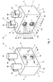
- Fig. 1 is schematically a perspective view of two manifolds
- Fig. 2 is a cross sectional view of a manifold, taken parallel to a top surface of a manifold of Fig. 1 trough a lower channel;
- Fig. 3 is schematically a cross sectional view of a row of manifolds showing a channel and a number of side channels;
- Fig. 4 is schematically a cross sectional view of a manifold, connected to a tool and a controller;
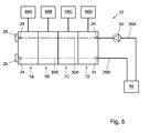
- Fig. 5 is schematically a fluid circuit comprising a row of stackable manifolds.
- a manifold has to be understood as including at least but not limited to an element comprising at least a through channel and a side channel in connection with the through channel, suitable for dividing off a part of a fluid stream from the through channel to the side channel and/or feeding a fluid from a side channel into the through channel.
- a manifold according to this disclosure can be a valve free manifold or can be provided with one or more valves and can at least be suitable for liquids or gasses or combinations thereof
- Manifolds according to the disclosure can include but are not limited to shut off valve manifolds, throttle manifolds, proportional valve manifolds, pressure regulating valve manifolds, safety valve manifolds, spool valve manifolds and other types of valve manifolds.
- Manifolds according to the description can for example but not limited to be manually, mechanically, electrically, pneumatically or hydraulically actuated.
- Stackable manifold has to be understood as at least including but not limited to manifolds that can be attached directly to each other, in a line of three or more, forming a substantially straight line.
- ports of the or each channel can be positioned symmetrical at opposite sides of the manifold, such that another stackable manifold can be positioned on either side of the stackable manifold, the or each channel thereof in fluid communication with a corresponding channel in that stackable manifold.
- each manifold 1A, 1B comprises a body 2, which can be substantially block shaped.
- the body 2 comprises a first side 3, visible in Fig. 1 of the left hand side manifold 1A, and an opposite second side 4, shown in Fig. 1 at the right hand side manifold 1B.
- Each manifold 1A, 1B further has a top 5, a bottom 6, a front 7 and a back 8. It should be noted that references to side, top, bottom, front and back are only used as relative terms, in relation to the drawings, and should not be construed as related to an intended positioning of the manifolds 1, unless specifically indicated otherwise.
- a manifold 1 can have at least one channel 9 extending through the body 2, from the first side 3 to the opposite second side 4. At the first side 3 the channel 9 can have or define a first port 10, whereas at the second side 4 the channel can have or define a second port 11.
- a side channel 12 can extend from the channel 9 to any one of the sides 3, 4, the top, bottom, front or back 5, 6, 7, 8, for connecting to an auxiliary circuit.
- the at least one side channel 12 can be directly or indirectly in fluid communication with the channel 9.
- the sides 3, 4 can be formed by side surfaces 13, 14 respectively, which can in an embodiment be substantially planar and can be parallel to each other.
- the top 5 and bottom 6 can in an embodiment comprise substantially planar top and bottom surfaces 15, 16, which can extend substantially parallel to each other and substantially perpendicular to the side surfaces 13, 14.
- the top surface 15 can connect the side surfaces 13, 14 at a first end, the bottom surface 16 at an opposite second end.
- the front 7 and back 8 can comprise front and back surfaces 17, 18, which can in an embodiment be substantially planar and can extend substantially parallel to each other and substantially perpendicular to the side surfaces 13, 14. They can connect the side surfaces 13, 14 at opposite sides.
- a surface area 19 around one or each of the ports 10, 11 can be provided, shown schematically dotted lines in Fig. 1 , which is substantially flat, whereas the rest of the relevant side surface 13, 14 can be for example set back relative to said surface area 19 or can be irregularly shaped.
- The, or each, surface area 19 can form a sealing surface, as will be discussed hereafter.
- each manifold can have a first channel 9A and a second channel 9B, extending through the body 2.
- the first and second channel 9A, 9B extend substantially parallel to each other and substantially perpendicular to the side surfaces 13, 14.
- the first channel 9A has a first end forming a first port 10A and a second end forming a second port 11A.
- the second channel 9B has a first end forming a first port 10B and a second end forming a second port 11B.
- a side channel 12 can be connected to one or each of the first and second channels 9A, 9B, between the first and second port 10A, B and 11A, B respectively.
- a seal 20 can be provided in at least one of the side surfaces 13, 14, extending in a frontal view of the relevant side surface around at least one port 10, 11.
- a circular groove 21 is provided in the second side surface 14, in which groove 21 a circular sealing ring 22 is provided.
- the sealing ring 22 can for example be a partly or wholly flexible ring, such as a rubber or plastic O-ring, quad ring or other suitably shaped ring, which when positioned in the groove 21 extends at least partly beyond the side surface 14.
- each of the second ports 11 is surrounded by a seal 20 formed by sealing ring 22.
- the inner diameter D 1 of the sealing ring 22 can be larger than the outer diameter D 2 of the port 10, 11 around which it is extending, such that a small area surface 23 is enclosed between the sealing ring 22 and the port 10, 11.
- an interface portion 24 can be provided in the or each channel 9 at at least one of the ports 10, 11 .
- the interface portion 24 can be designed to receive one of a stop 25, shown in Fig. 2 in dash-dotted lines at the left hand side, or a conduit 26 of a fluid circuit 27, said conduit 26 being represented in Fig. 2 by a dash-dotted line at the right hand side.
- the stop 25 and/or the conduit 26 can be connected to or be interfacing with the relevant interface portion 24 in a fluid tight configuration.
- the interface portion can comprise screw thread T internal to the channel 9 at the relevant port 10, 11.
- the interface portion 24 can be provided with at least one part of a bayonet coupling.
- the interface portion 24 can be provided with a press fit coupling or any other suitable type of coupling for direct or indirect fluid tight coupling with either a stop 25 or a conduit 26.
- each body 2 of a manifold 1 can comprise at least one and preferably a number of through bores 28 extending between the opposite side surfaces 13, 14, which when a number of these manifolds are connected properly to each other in series, form bores 28 extending through the entire series.
- Fig. 3 set of manifolds 1 is shown, forming a row 29.
- the row 29 comprises a series of interconnected manifolds 1, in this embodiment four manifolds 1A - D. In other embodiments there can be two or more manifolds in a row 33.
- the manifolds 1A - D are placed such that a second side surface 14 of each of the manifolds 1B - D is placed adjacent or in abutment with a first side surface 13 of a manifold 1A - C next to it in the row 29.
- the sealing ring 22 in the groove 21 of a manifold 1B - D can be positioned against an area surface 19 of the first side surface 13 of the adjacent manifold 1A - C, such that a sealing 20 is accomplished.
- Each manifold 1A - D comprises a channel 9 with a first 10 and second port 11.
- a second port 11 in a second side surface 14 of a manifold 1B - D is positioned next to a first port 10 of the adjacent manifold 1A - C, such that these are in fluid communication.
- each channel 9 forms a channel part of a extended channel 30 extending through the entire series or row 29 of manifolds 1.
- Different side channels 12A - D are provided extending from the extended channel 30.
- a stop 25 is positioned in the interface portion 24 in the channel 9 of the last manifold 1D in the row 29, whereas a conduit 26 can interface with the interface portion 24 of the first manifold 1A in the row 29, in this embodiment at the left hand side of the row 29.
- a bolt 31 extends through the or each of bores 28 and is secured by nuts 32, such that the manifolds 1A - D are tightly pulled together, thereby securing the sealing by the sealing rings 22 against the respective surface areas 19.
- a series of stackable manifolds 1 can be provided, directly or indirectly connected to or incorporated in a fluid circuit 27, whereas different types of manifolds 1 or manifolds 1 having, different types of valves as disclosed in this description can be used in such series or row 29.
- a row 29 can comprise other items, besides a series of manifolds 1.
- Fig. 1 the manifolds 1A and B have been shown which comprise two valves 33 for closing off and opening at least partly each a side channel 12 from one or each of the channels 9A, B.
- Two valve actuator 34 are shown above the top surface 15, each for actuating one of the valves 33 as will be explained hereafter.
- Each valve actuator 34 is provided with an electrical coupling 35 for connecting the actuator 34 to a controller 36.
- the valve actuator 34 can be electrically operated and/or controlled.
- the valve actuators can comprise a solenoid 37.
- Fig. 4 schematically discloses in cross sectional view a manifold 1 according to or similar to Fig. 1 , wherein for sake of clarity only one valve 33 and only one valve actuator 34 is shown, connected to the controller 36. It will be appreciated that this valve 33 is only shown by way of example and, as indicated before, should by no means be construed as limiting the disclosure to this valve only or to manifolds having one or more valves only.
- Fig. 4 shows a cross section of an embodiment of a manifold 1, wherein a first and second channel 9A, B are provided above each other, seen in a direction between the top 5 and bottom 6.
- a bore 38 extends from the top surface 15 towards the bottom surface 16.
- a piston rod 39 extends through said bore 38 and is provided with two circumferential grooves 40, 41. Except for these grooves 40, 41 the outer surface 42 of the rod 39 is in sealing but sliding engagement with the inner surface 43 of the bore 38.
- From the first channel 9A a first side channel 12A extends into the bore 38.
- a second side channel 12B extends from the second channel 9B into the bore 38.
- two auxiliary channels 44, 45 extend to auxiliary ports 46, 47 in the back 8 of the manifold respectively.
- a valve actuator 34 is connected to the piston rod 38 for moving the piston rod 38 in an axial direction F.
- the valve 33 In the position of the piston rod 38 shown in Fig. 4 the valve 33 is closed. Neither the first side channel 12A is in communication with the first auxiliary channel 44, nor the second side channel 12B with the second auxiliary channel 45.
- the valve 33 By moving the piston rod 38 by the valve actuator 34 in the direction of the top 5, the valve 33 can be opened, bringing the first side channel 12A in fluid communication with the first auxiliary channel 44 through the first groove 40.
- the second side channel 12B By moving the piston rod 38 with the valve actuator 34 in the direction of the bottom 6, the second side channel 12B can be brought into fluid communication with the second auxiliary channel 45 through the second groove 41.
- the first and second auxiliary ports 46, 47 can in this embodiment be connected to a work tool 48 or other device or part thereof to be operated, powered, actuated or otherwise controlled or influenced.
- the auxiliary ports 46, 47 can be connected to a source of fluid, relief means, or measurement equipment such as but not limited to a pressure gauge or the like or other equipment.
- a fluid circuit 27 is schematically shown, comprising a row 29 of stackable manifolds 1.
- the circuit 27 comprises a reservoir 49 for a fluid, such as but not limited to a hydraulic fluid.
- a feed conduit 26A extends from the reservoir 49 and is connected to an interface portion 24 of the manifold 1D of the first channel 9A at the right hand end of the row 29.
- a pump 50 is provided in the feed conduit 26A.
- a return conduit 26B is connected to the interface portion 24 of the second channel 9B of the same manifold 1D.
- the opposite ends of the extended channels 30A, B are closed off by stops 25, provided in the ports 10A, B and engaging the relevant engagement portions 24.
- Equipment, such as work tools 50A - D is connected to the manifolds 1A - B.
- a row 29 of stackable manifolds 1 can be set up by setting a series of manifolds 1 with first and second side surfaces 13, 14 adjacent each other, such that extended channels 30 A,B are formed by the first and second channels 9A, 9B of the manifolds 1 in the series.
- Sealing rings 22, inserted in the grooves 21 in the second side surfaces 14 are facing surface areas 19 or sealing areas of the adjacent first side surfaces 13 of the adjacent manifolds 1.
- bolts 31 are inserted into the bores 28 which are tightened by nuts 32, such that the manifolds 1 in the series are pulled together, compressing the sealing rings 22 against the relevant first side surfaces 13.
- stops 25 are provided in the second ports 11 of a manifold 1 at a first end of the series, engaging the engaging portions 24 thereof and closing of these ports 11.
- a feed conduit 26A is connected to the engaging portion 24 at the first port 10 of the first channel 9A of the manifold 1 at the second end, opposite the first end.
- a return conduit 26B is connected to the first port 10 of the second channel 9B of the manifold 1 at the second end of the series, engaging the engaging portion 24 thereof.
- the feed conduit 26A and the return conduit 26B can be connected to the reservoir 49 and the pump 50 is provided in the feed conduit 26A.
- a fluid circuit 27 including the row 29 of manifolds 1 is formed.
- Equipment 48 such as work tools, metering equipment, engine parts, drive train parts, safety means and other equipment, shown in Fig. 5 schematically as boxes 48A - D can be connected to the manifolds 1 through the auxiliary ports 46, 47.
- the valve actuators 34 can be connected to the controller 36.
- the fluid pressure can be raised in the feed conduit 26A and in the first extended channel 30A. This thus becomes a high pressure side of the manifolds 1, also referred to as high pressure gallery.
- the second extended channel 30B, connected to the return conduit 26B, will form the low pressure side of the manifolds, also referred to as low pressure gallery. High and low have to be understood as relative to each other and can but need not be pressures normally applied in fluid circuits 27.
- valves 33 of any one of the manifolds 1, if available can be opened and closed fully or partly, based on the necessity or desire to feed fluid from the high pressure side to a piece of equipment 48A - D or to return fluid from such piece of equipment 48A - D to the low pressure side of the manifolds 1 and back to the reservoir 49.
- the equipment 48 can be operated, monitored, pressurized, depressurized or otherwise controlled by the fluid.
- a row 29 of manifolds 1 can be used having only one extended channel 30. Then the feed conduit 26A can for example be connected to a first port 10 of the extended channel 30 at a first end of the row 29, by engaging the relevant engaging portion 24, and the return conduit 26B can be connected to the second port 11 at the opposite end of the row 29, by engaging the relevant engaging portion 24.
- pressurized fluid can be forwarded to the pieces of equipment 48 from the respective manifolds 1 they are connected to.
- two or more rows 29 of manifolds 1 can be connected in series and/or parallel to each other in a fluid circuit 31.
- 25 ports 10, 11 at a first end of a series of manifolds can be closed off simultaneously by a single stop 25 covering both or all ports 10, 11 at that end.
- the bores 28 in a manifold 1 can be provided in at least one end thereof by screw thread or such coupling, and at another end with a rotatably retained screw or other coupler for cooperating with the screw thread or coupling in a bore of an adjacent bore 28 of an adjacent bore 28 of an adjacent manifold 1, for connecting said manifolds 1 to each other.
- bolts 31 and nuts 32 other connecting elements can be used for coupling manifolds 1, such as straps or couplers attached to the outside of the manifolds.
Landscapes
- Engineering & Computer Science (AREA)
- Physics & Mathematics (AREA)
- Fluid Mechanics (AREA)
- Mechanical Engineering (AREA)
- General Engineering & Computer Science (AREA)
- Valve Housings (AREA)
- Fluid-Pressure Circuits (AREA)
Abstract
Description
- The present invention relates generally to manifolds and, more particularly, to stackable manifolds.
- Fluid circuits are used in for example engine control systems, systems for control of tools and machines, power steering and the like. Manifolds can be used in such systems for redirecting part of a fluid stream to different parts of such system. To this end such manifold may include a body and at least two channels extending through said body, between opposite sides thereof. At least one side channel is connected to each of said channels, such that a fluid stream can be directed partly from a channel into a side channel or from a side channel into a channel. The channels can be incorporated into a circuit for a liquid or a gas. One of the channels can be an inlet channel, the other an outlet channel. When different parts of a system have to be fed from such fluid circuit manifolds can be stacked by interconnecting the bodies thereof, such that the channels in adjacent manifolds are brought into fluid connection with each other, forming extended channels through all of the manifolds. If the manifolds are thus stacked, at a first end the channels will normally be closed off by a specific closing block, differing from the manifolds, preventing fluid from leaving the channels. At an opposite second end a specific connecting block, differing from the manifolds, will be connected to the relevant manifold, for connecting a feeding conduit and a discharging conduit to the respective channels.
- A stackable manifold arrangement is manufactured and sold by Sauer-Danfoss Company, USA,
type PVG 32. This manifold is designed as a proportional valve and comprises a body having two parallel channels extending from one side surface of the body to the opposite side surface. Inlet ports and outlet ports of the channels are provided in the side surfaces. A side channel extends from each of the channels. Each of the side channels is provided with an end opening in a top surface of the body, which top surface extends perpendicular to the side surfaces. Conduits can be connected to these end openings for feeding and returning fluid from the channels to a device to be operated by said fluid. A number of these manifolds can be stacked in a row, such that the channels of the respective manifolds are interconnected to form two extended channels, extending through the entire row. - In this known manifold arrangement at a first end of the row an end,block is provided, forming a stop and closing off the ends of the channels adjacent said first end. At the opposite second end of the row a connecting block is provided, connected to the row and having connecting elements for connecting a feeding conduit to a first of the two extended channels and a discharge conduit to the other of the two extended channels. The manifolds, the end block and the connecting block are all provided with bores, communicating with each other in said row, through which communicating holes bolts extend for attaching the manifolds and blocks to each other.
- Although with this known stackable manifold arrangement it is possible to incorporate a member of manifolds in a relatively small volume, connected to or incorporated in a fluid circuit, the volume is still relatively large, due to the end block and the connecting block. Moreover, the end block and the connecting block are different from the manifolds and are relatively costly. Furthermore the end block and connecting block add to the time necessary for installing and disassembling the stacked manifolds, for example during maintenance or repair.
- The disclosed stackable manifold and manifold arrangements are directed to addressing at least one of the problems or disadvantages set forth above.
- In one aspect, the disclosure is directed to a stackable manifold. The manifold comprises a body having at least one channel extending through the body. At a first side of the body the channel comprises a first port and at an opposite second side of the body a second port. Around at least one of the first port and the second port of the channel a seal is provided. Furthermore the channel is provided with an interface portion at at least one of the first port and the second port, for a fluid circuit or a stop.
- In another aspect, the present disclosure is directed to a set of stackable manifolds, comprising at least a first and a second manifold. Each of the first and second manifold comprises a body with at least a first channel extending there through. The channel has at least a first end opening and a second end opening. The first manifold is connected to the second manifold, such that the first end opening of the channel of the first manifold is in fluid communication with the second end opening of the channel of the second manifold. At least one seal is provided between the first and second manifold, which seal extends around the communicating first and second end openings. The first channel of at least one of the first and second manifolds is provided, at least at one of the end openings, with an interface portion for a fluid circuit or a stop.
- In still another aspect, the present disclosure is directed to a fluid circuit comprising a row of manifolds. The row of manifolds includes a series of stackable manifolds. First and second channels extend through at least a number of the manifolds in the row, wherein each of the manifolds in the series comprises a part of each of said first and second channels. Seals are provided around connecting openings of channel parts in adjacent manifolds in the series. Interface portions are provided in channel parts at least in a manifold at a first end of the series and in a manifold at an opposite second end of the series. At least one of the first and second channels is closed off at a first end of the channel by a stop connected to the interface portion and/or a conduit is connected to the interface portion of at least one of the first and second channels at a second end of the channel.
- Other features and aspects of this disclosure will be apparent from the following description and drawings.
-
Fig. 1 is schematically a perspective view of two manifolds; -
Fig. 2 is a cross sectional view of a manifold, taken parallel to a top surface of a manifold ofFig. 1 trough a lower channel; -
Fig. 3 is schematically a cross sectional view of a row of manifolds showing a channel and a number of side channels; -
Fig. 4 is schematically a cross sectional view of a manifold, connected to a tool and a controller; and -
Fig. 5 is schematically a fluid circuit comprising a row of stackable manifolds. - In the description the same or similar features or elements have the same or corresponding reference signs. The embodiments shown are only shown and discussed by way of examples and should not be construed as limiting the disclosure.
- In the disclosure a manifold has to be understood as including at least but not limited to an element comprising at least a through channel and a side channel in connection with the through channel, suitable for dividing off a part of a fluid stream from the through channel to the side channel and/or feeding a fluid from a side channel into the through channel. A manifold according to this disclosure can be a valve free manifold or can be provided with one or more valves and can at least be suitable for liquids or gasses or combinations thereof Manifolds according to the disclosure can include but are not limited to shut off valve manifolds, throttle manifolds, proportional valve manifolds, pressure regulating valve manifolds, safety valve manifolds, spool valve manifolds and other types of valve manifolds. Manifolds according to the description can for example but not limited to be manually, mechanically, electrically, pneumatically or hydraulically actuated. Stackable manifold has to be understood as at least including but not limited to manifolds that can be attached directly to each other, in a line of three or more, forming a substantially straight line. In stackable manifolds according to this disclosure ports of the or each channel can be positioned symmetrical at opposite sides of the manifold, such that another stackable manifold can be positioned on either side of the stackable manifold, the or each channel thereof in fluid communication with a corresponding channel in that stackable manifold.
- In
Fig. 1 twomanifolds Fig. 1 eachmanifold body 2, which can be substantially block shaped. Thebody 2 comprises afirst side 3, visible inFig. 1 of the lefthand side manifold 1A, and an oppositesecond side 4, shown inFig. 1 at the righthand side manifold 1B. Eachmanifold top 5, abottom 6, afront 7 and aback 8. It should be noted that references to side, top, bottom, front and back are only used as relative terms, in relation to the drawings, and should not be construed as related to an intended positioning of themanifolds 1, unless specifically indicated otherwise. - As is schematically shown in
Fig. 3 , amanifold 1 according to this disclosure can have at least onechannel 9 extending through thebody 2, from thefirst side 3 to the oppositesecond side 4. At thefirst side 3 thechannel 9 can have or define afirst port 10, whereas at thesecond side 4 the channel can have or define asecond port 11. Aside channel 12 can extend from thechannel 9 to any one of thesides side channel 12 can be directly or indirectly in fluid communication with thechannel 9. - In an embodiment the
sides side surfaces bottom surfaces top surface 15 can connect the side surfaces 13, 14 at a first end, thebottom surface 16 at an opposite second end. Similarly thefront 7 and back 8 can comprise front and back surfaces 17, 18, which can in an embodiment be substantially planar and can extend substantially parallel to each other and substantially perpendicular to the side surfaces 13, 14. They can connect the side surfaces 13, 14 at opposite sides. - In an alternative embodiment a
surface area 19 around one or each of theports Fig. 1 , which is substantially flat, whereas the rest of therelevant side surface surface area 19 or can be irregularly shaped. The, or each,surface area 19 can form a sealing surface, as will be discussed hereafter. - In an embodiment as shown in
Fig. 1 each manifold can have afirst channel 9A and asecond channel 9B, extending through thebody 2. The first andsecond channel first channel 9A has a first end forming afirst port 10A and a second end forming asecond port 11A. Thesecond channel 9B has a first end forming afirst port 10B and a second end forming asecond port 11B. Aside channel 12 can be connected to one or each of the first andsecond channels second port 10A, B and 11A, B respectively. - In a
manifold 1 according to the disclosure aseal 20 can be provided in at least one of the side surfaces 13, 14, extending in a frontal view of the relevant side surface around at least oneport Fig. 1 and2 acircular groove 21 is provided in thesecond side surface 14, in which groove 21 acircular sealing ring 22 is provided. The sealingring 22 can for example be a partly or wholly flexible ring, such as a rubber or plastic O-ring, quad ring or other suitably shaped ring, which when positioned in thegroove 21 extends at least partly beyond theside surface 14. InFig. 1 each of thesecond ports 11 is surrounded by aseal 20 formed by sealingring 22. The inner diameter D1 of the sealingring 22 can be larger than the outer diameter D2 of theport small area surface 23 is enclosed between the sealingring 22 and theport - In the or each
channel 9 at at least one of theports interface portion 24 can be provided. Theinterface portion 24 can be designed to receive one of astop 25, shown inFig. 2 in dash-dotted lines at the left hand side, or aconduit 26 of afluid circuit 27, saidconduit 26 being represented inFig. 2 by a dash-dotted line at the right hand side. Thestop 25 and/or theconduit 26 can be connected to or be interfacing with therelevant interface portion 24 in a fluid tight configuration. In an embodiment the interface portion can comprise screw thread T internal to thechannel 9 at therelevant port interface portion 24 can be provided with at least one part of a bayonet coupling. In a still further embodiment theinterface portion 24 can be provided with a press fit coupling or any other suitable type of coupling for direct or indirect fluid tight coupling with either astop 25 or aconduit 26. - As can be seen in
Fig. 1 - 3 , eachbody 2 of amanifold 1 can comprise at least one and preferably a number of throughbores 28 extending between the opposite side surfaces 13, 14, which when a number of these manifolds are connected properly to each other in series, form bores 28 extending through the entire series. - In
Fig. 3 set ofmanifolds 1 is shown, forming arow 29. Therow 29 comprises a series ofinterconnected manifolds 1, in this embodiment fourmanifolds 1A - D. In other embodiments there can be two or more manifolds in arow 33. Themanifolds 1A - D are placed such that asecond side surface 14 of each of themanifolds 1B - D is placed adjacent or in abutment with afirst side surface 13 of a manifold 1A - C next to it in therow 29. The sealingring 22 in thegroove 21 of a manifold 1B - D can be positioned against anarea surface 19 of thefirst side surface 13 of theadjacent manifold 1A - C, such that a sealing 20 is accomplished. Each manifold 1A - D comprises achannel 9 with a first 10 andsecond port 11. Asecond port 11 in asecond side surface 14 of a manifold 1B - D is positioned next to afirst port 10 of theadjacent manifold 1A - C, such that these are in fluid communication. Thus eachchannel 9 forms a channel part of aextended channel 30 extending through the entire series orrow 29 ofmanifolds 1.Different side channels 12A - D are provided extending from the extendedchannel 30. At the right hand side astop 25 is positioned in theinterface portion 24 in thechannel 9 of thelast manifold 1D in therow 29, whereas aconduit 26 can interface with theinterface portion 24 of thefirst manifold 1A in therow 29, in this embodiment at the left hand side of therow 29. Abolt 31 extends through the or each ofbores 28 and is secured bynuts 32, such that themanifolds 1A - D are tightly pulled together, thereby securing the sealing by the sealing rings 22 against therespective surface areas 19. In a row 29 a series ofstackable manifolds 1 can be provided, directly or indirectly connected to or incorporated in afluid circuit 27, whereas different types ofmanifolds 1 ormanifolds 1 having, different types of valves as disclosed in this description can be used in such series orrow 29. Arow 29 can comprise other items, besides a series ofmanifolds 1. - In
Fig. 1 themanifolds 1A and B have been shown which comprise twovalves 33 for closing off and opening at least partly each aside channel 12 from one or each of thechannels 9A, B.Two valve actuator 34 are shown above thetop surface 15, each for actuating one of thevalves 33 as will be explained hereafter. Eachvalve actuator 34 is provided with anelectrical coupling 35 for connecting theactuator 34 to acontroller 36. In an embodiment thevalve actuator 34 can be electrically operated and/or controlled. In an embodiment the valve actuators can comprise asolenoid 37. -
Fig. 4 schematically discloses in cross sectional view amanifold 1 according to or similar toFig. 1 , wherein for sake of clarity only onevalve 33 and only onevalve actuator 34 is shown, connected to thecontroller 36. It will be appreciated that thisvalve 33 is only shown by way of example and, as indicated before, should by no means be construed as limiting the disclosure to this valve only or to manifolds having one or more valves only. -
Fig. 4 shows a cross section of an embodiment of amanifold 1, wherein a first andsecond channel 9A, B are provided above each other, seen in a direction between the top 5 andbottom 6. A bore 38 extends from thetop surface 15 towards thebottom surface 16. Apiston rod 39 extends through said bore 38 and is provided with twocircumferential grooves grooves outer surface 42 of therod 39 is in sealing but sliding engagement with theinner surface 43 of thebore 38. From thefirst channel 9A afirst side channel 12A extends into thebore 38. Asecond side channel 12B extends from thesecond channel 9B into thebore 38. From thebore 38 twoauxiliary channels auxiliary ports back 8 of the manifold respectively. Avalve actuator 34 is connected to thepiston rod 38 for moving thepiston rod 38 in an axial direction F. In the position of thepiston rod 38 shown inFig. 4 thevalve 33 is closed. Neither thefirst side channel 12A is in communication with the firstauxiliary channel 44, nor thesecond side channel 12B with the secondauxiliary channel 45. By moving thepiston rod 38 by thevalve actuator 34 in the direction of the top 5, thevalve 33 can be opened, bringing thefirst side channel 12A in fluid communication with the firstauxiliary channel 44 through thefirst groove 40. By moving thepiston rod 38 with thevalve actuator 34 in the direction of thebottom 6, thesecond side channel 12B can be brought into fluid communication with the secondauxiliary channel 45 through thesecond groove 41. The first and secondauxiliary ports work tool 48 or other device or part thereof to be operated, powered, actuated or otherwise controlled or influenced. In another embodiment theauxiliary ports - In
Fig. 5 afluid circuit 27 is schematically shown, comprising arow 29 ofstackable manifolds 1. Thecircuit 27 comprises a reservoir 49 for a fluid, such as but not limited to a hydraulic fluid. Afeed conduit 26A extends from the reservoir 49 and is connected to aninterface portion 24 of the manifold 1D of thefirst channel 9A at the right hand end of therow 29. Apump 50 is provided in thefeed conduit 26A. Areturn conduit 26B is connected to theinterface portion 24 of thesecond channel 9B of thesame manifold 1D. The opposite ends of theextended channels 30A, B are closed off bystops 25, provided in theports 10A, B and engaging therelevant engagement portions 24. Equipment, such as work tools 50A - D, is connected to themanifolds 1A - B. - A
row 29 ofstackable manifolds 1 can be set up by setting a series ofmanifolds 1 with first and second side surfaces 13, 14 adjacent each other, such thatextended channels 30 A,B are formed by the first andsecond channels manifolds 1 in the series. Sealing rings 22, inserted in thegrooves 21 in the second side surfaces 14 are facingsurface areas 19 or sealing areas of the adjacent first side surfaces 13 of theadjacent manifolds 1. Thenbolts 31 are inserted into thebores 28 which are tightened bynuts 32, such that themanifolds 1 in the series are pulled together, compressing the sealing rings 22 against the relevant first side surfaces 13. Then stops 25 are provided in thesecond ports 11 of amanifold 1 at a first end of the series, engaging the engagingportions 24 thereof and closing of theseports 11. Afeed conduit 26A is connected to the engagingportion 24 at thefirst port 10 of thefirst channel 9A of themanifold 1 at the second end, opposite the first end. Areturn conduit 26B is connected to thefirst port 10 of thesecond channel 9B of themanifold 1 at the second end of the series, engaging the engagingportion 24 thereof. Thefeed conduit 26A and thereturn conduit 26B can be connected to the reservoir 49 and thepump 50 is provided in thefeed conduit 26A. Thus afluid circuit 27 including therow 29 ofmanifolds 1 is formed. -
Equipment 48 such as work tools, metering equipment, engine parts, drive train parts, safety means and other equipment, shown inFig. 5 schematically asboxes 48A - D can be connected to themanifolds 1 through theauxiliary ports controller 36. - By driving the
pump 50 or by other well known means the fluid pressure can be raised in thefeed conduit 26A and in the firstextended channel 30A. This thus becomes a high pressure side of themanifolds 1, also referred to as high pressure gallery. The secondextended channel 30B, connected to thereturn conduit 26B, will form the low pressure side of the manifolds, also referred to as low pressure gallery. High and low have to be understood as relative to each other and can but need not be pressures normally applied influid circuits 27. - By now operating the
valves 33 by actuating thevalve actuators 34 through thecontroller 36,valves 33 of any one of themanifolds 1, if available, can be opened and closed fully or partly, based on the necessity or desire to feed fluid from the high pressure side to a piece ofequipment 48A - D or to return fluid from such piece ofequipment 48A - D to the low pressure side of themanifolds 1 and back to the reservoir 49. Thus theequipment 48 can be operated, monitored, pressurized, depressurized or otherwise controlled by the fluid. - In an alternative embodiment a
row 29 ofmanifolds 1 can be used having only one extendedchannel 30. Then thefeed conduit 26A can for example be connected to afirst port 10 of theextended channel 30 at a first end of therow 29, by engaging the relevant engagingportion 24, and thereturn conduit 26B can be connected to thesecond port 11 at the opposite end of therow 29, by engaging the relevant engagingportion 24. In such embodiment pressurized fluid can be forwarded to the pieces ofequipment 48 from therespective manifolds 1 they are connected to. In a further embodiment two ormore rows 29 ofmanifolds 1 can be connected in series and/or parallel to each other in afluid circuit 31. In a stillfurther embodiment 25ports single stop 25 covering both or allports - In a still further embodiment the
bores 28 in amanifold 1 can be provided in at least one end thereof by screw thread or such coupling, and at another end with a rotatably retained screw or other coupler for cooperating with the screw thread or coupling in a bore of anadjacent bore 28 of anadjacent bore 28 of anadjacent manifold 1, for connecting saidmanifolds 1 to each other. In stead of or next tobores 28,bolts 31 andnuts 32 other connecting elements can be used forcoupling manifolds 1, such as straps or couplers attached to the outside of the manifolds. - Although embodiments have been disclosed and described herein, improvements and modifications, including combinations of such embodiments or parts thereof, may be incorporated without departing from the scope of the claims and are considered to be disclosed herein also.
Claims (20)
- Stackable manifold, comprising:a body having at least one channel extending through the body;the channel having a first port at a first side of the body and a second port at an opposite second side;wherein around at least one of the first port or second port of the channel a seal is provided; andat least one of the first port or second port of the channel is provided with an interface portion for a fluid circuit or a stop.
- Stackable manifold according to claim 1, wherein at least two channels extend through the body having a first port at a first side of the body and a second port at an opposite second side, wherein a seal is provided around at least one of the first port and the second port of each channel.
- Stackable manifold according to claim 1 or 2, wherein the or each seal comprises at least one at least partly flexible ring.
- Stackable manifold according to any one of claims 1 - 3, wherein the manifold has a first side surface at the first side in which at least one of the first port and the second port of the at least one channel is provided, wherein around the or each first port or second port in said first side surface at least one seal is provided.
- Stackable manifold according to claim 4, wherein the manifold has a second side surface at the second side, in which the other of the first port or second port of the at least one channel is provided, which second side surface has at least one surface area forming a sealing surface.
- Stackable manifold according to any one of claims 1 - 5, wherein the manifold has a first and a second side surface, wherein one of the first port or second port of the or each channel is provided in the first side surface and the other of the first port and the second port is provided in the second side surface, wherein the first and second side surface have surface areas extending around the first port and second port of the or each channel, which surface areas extend substantially parallel to each other.
- Stackable manifold according to claim 6, wherein the first and second side surface are substantially flat and parallel to each other.
- Stackable manifold according to any one of claims 1 - 7, wherein the interface portion is provided at least partially inside the at least one channel.
- Stackable manifold according to any one of the preceding claims, wherein the interface portion comprises a screw thread or a bayonet coupling part or a press fit coupling.
- Stackable manifold according to any one of the preceding claims, wherein the manifold comprises at least one coupling element.
- Stackable manifold according to claim 10, wherein the at least one coupling element comprises an opening through the manifold for accommodating a coupling pin.
- Stackable manifold according to any one of the previous claims, wherein the manifold comprises at least one side channel extending from the or at least one of the channels, wherein a valve element is provided for opening or closing off at least partly the side channel to or from the channel.
- Stackable manifold according to claim 12, wherein an actuator is provided, coupled to the valve element.
- Stackable manifold according to claim 12 or 13, including at least two channels, wherein a side channel is connected to each of the channels, and a valve member is provided for each side channel.
- Set of stackable manifolds, comprising at least a first and a second manifold, wherein each of the first and second manifold comprises:a body having at least a first channel extending through said body;the channel having a first end opening and a second end opening;wherein the first manifold is connected to the second manifold, such that:the first end opening of the first channel of the first manifold is in fluid connection with a second end opening of the first channel of the second manifold; andwherein at least one seal is provided between the first and second manifold, the seal extending around fluidly connected first and second end openings; andthe first channel of at least one of the first and second manifold is provided, at least at one of the end openings, with an interface portion for a fluid circuit or a stop.
- Set of stackable manifolds according to claim 15, wherein the or each interface portion is provided inside the first channel, preferably integrally with the body.
- Set of stackable manifolds according to claim 15 or 16, wherein said manifolds form a row, wherein a stop is connected to or in at least one of the first or second end openings of a manifold at a first end of the row and at least one conduit is connected to or in at least one of the other of the first and second end openings of the manifold at the opposite second end of the row.
- Set of stackable manifolds according to claim 17, wherein at least one of the at least one stop and the at least one conduit is connected to an interface portion of the relevant channel.
- Set of stackable manifolds according to any one of claims 15 - 18, wherein the manifolds are coupled to each other by at least one coupling element extending through at least two of the manifolds.
- Fluid circuit comprising a row of manifolds, comprising:a series of stackable manifolds,first and second channels extending through at least a number of the manifolds in the row;each of the manifolds of the series comprising a part of each of the channels;seals provided around connecting openings of channel parts in adjacent manifolds, between adjacent manifolds in the series;interface portions being provided in the channel parts in a manifold at a first end of the series and in a manifold at an opposite second end of the series;wherein at least one of the channels at the first end of the series is closed off by a stop; and/ora conduit is connected to the interface portion in at least one of the channels of the manifold at the second end of the series.
Priority Applications (3)
| Application Number | Priority Date | Filing Date | Title |
|---|---|---|---|
| EP07122291A EP2068005A1 (en) | 2007-12-04 | 2007-12-04 | Stackable manifold having integral interface portion |
| PCT/US2008/013310 WO2009073183A1 (en) | 2007-12-04 | 2008-12-03 | Stackable manifold having integral interface portion |
| CN2008801189564A CN101883926A (en) | 2007-12-04 | 2008-12-03 | Have whole interface section can be stacked manifold |
Applications Claiming Priority (1)
| Application Number | Priority Date | Filing Date | Title |
|---|---|---|---|
| EP07122291A EP2068005A1 (en) | 2007-12-04 | 2007-12-04 | Stackable manifold having integral interface portion |
Publications (1)
| Publication Number | Publication Date |
|---|---|
| EP2068005A1 true EP2068005A1 (en) | 2009-06-10 |
Family
ID=39345186
Family Applications (1)
| Application Number | Title | Priority Date | Filing Date |
|---|---|---|---|
| EP07122291A Ceased EP2068005A1 (en) | 2007-12-04 | 2007-12-04 | Stackable manifold having integral interface portion |
Country Status (3)
| Country | Link |
|---|---|
| EP (1) | EP2068005A1 (en) |
| CN (1) | CN101883926A (en) |
| WO (1) | WO2009073183A1 (en) |
Citations (4)
| Publication number | Priority date | Publication date | Assignee | Title |
|---|---|---|---|---|
| FR2250907A1 (en) * | 1973-11-09 | 1975-06-06 | Bouteille Daniel | Assembly baseplates for pneumatic or hydraulic distributors - tongue and groove are standard modules which connect with into rigid block |
| EP0754867A2 (en) * | 1995-07-21 | 1997-01-22 | Smc Corporation | Chaine valve assembly |
| EP1580438A2 (en) * | 2004-03-26 | 2005-09-28 | Husco International, Inc. | Hydraulic valve section with reduced bore distortion |
| WO2006093872A1 (en) | 2005-02-28 | 2006-09-08 | Swagelok Company | Modular system with captivated pastener assemblies |
Family Cites Families (1)
| Publication number | Priority date | Publication date | Assignee | Title |
|---|---|---|---|---|
| US4770210A (en) * | 1987-07-23 | 1988-09-13 | Mac Valves, Inc. | Valve manifold stacking base |
-
2007
- 2007-12-04 EP EP07122291A patent/EP2068005A1/en not_active Ceased
-
2008
- 2008-12-03 WO PCT/US2008/013310 patent/WO2009073183A1/en not_active Ceased
- 2008-12-03 CN CN2008801189564A patent/CN101883926A/en active Pending
Patent Citations (4)
| Publication number | Priority date | Publication date | Assignee | Title |
|---|---|---|---|---|
| FR2250907A1 (en) * | 1973-11-09 | 1975-06-06 | Bouteille Daniel | Assembly baseplates for pneumatic or hydraulic distributors - tongue and groove are standard modules which connect with into rigid block |
| EP0754867A2 (en) * | 1995-07-21 | 1997-01-22 | Smc Corporation | Chaine valve assembly |
| EP1580438A2 (en) * | 2004-03-26 | 2005-09-28 | Husco International, Inc. | Hydraulic valve section with reduced bore distortion |
| WO2006093872A1 (en) | 2005-02-28 | 2006-09-08 | Swagelok Company | Modular system with captivated pastener assemblies |
Non-Patent Citations (1)
| Title |
|---|
| SAUER-DANFOSS: "Combination Module PVGI Tech Note", February 2002, SAUER-DANFOSS, AMES, USA, XP002479830 * |
Also Published As
| Publication number | Publication date |
|---|---|
| WO2009073183A1 (en) | 2009-06-11 |
| CN101883926A (en) | 2010-11-10 |
Similar Documents
| Publication | Publication Date | Title |
|---|---|---|
| KR100286707B1 (en) | Pipe joints for hydraulic equipment | |
| US5699834A (en) | Manifold-type solenoid valves | |
| JP4919002B2 (en) | Manifold solenoid valve assembly | |
| CN101324280B (en) | Manifold-type solenoid valve apparatus having stop valve | |
| US10502240B2 (en) | Open center control valve | |
| US8061379B2 (en) | Manifold solenoid valve | |
| CN108350911B (en) | Assembly of a manifold module, a valve housing and a slide valve assembly for a manifold group | |
| US7021332B2 (en) | Hydraulic valve section with reduced bore distortion | |
| KR20180020176A (en) | Multi-Integral Manifold Valves | |
| JP4756119B2 (en) | Valve mounting mechanism for base member | |
| JP4016152B2 (en) | Switching valve assembly | |
| EP0957300A2 (en) | Manifold for change-over valve | |
| US20110132473A1 (en) | Hydraulic control valve assembly with monolithic body and single spool port lock | |
| GB2475192A (en) | Fluid flow control apparatus | |
| WO2009101388A1 (en) | An isolation valve manifold | |
| US6170520B1 (en) | Pressure control valve for solenoid valve aggregate and solenoid valve assembly provided with the same | |
| EP2068005A1 (en) | Stackable manifold having integral interface portion | |
| US6550368B2 (en) | Fluid power interlock system | |
| EP0943813B1 (en) | Shuttle valve manifold | |
| CN114893466A (en) | Combined valve group | |
| US12442394B2 (en) | Valve manifold, valve and actuator assembly | |
| JP2804227B2 (en) | Manifold solenoid valve | |
| KR20170143302A (en) | unified modular blovks for pneumatic system of ship engine starting | |
| JP2005016564A (en) | Pressure relief valve, assembly having pressure relief valve, and injection molding machine with assembly having pressure relief valve | |
| WO2022010631A1 (en) | Fluid conduit connector system |
Legal Events
| Date | Code | Title | Description |
|---|---|---|---|
| PUAI | Public reference made under article 153(3) epc to a published international application that has entered the european phase |
Free format text: ORIGINAL CODE: 0009012 |
|
| AK | Designated contracting states |
Kind code of ref document: A1 Designated state(s): AT BE BG CH CY CZ DE DK EE ES FI FR GB GR HU IE IS IT LI LT LU LV MC MT NL PL PT RO SE SI SK TR |
|
| AX | Request for extension of the european patent |
Extension state: AL BA HR MK RS |
|
| 17P | Request for examination filed |
Effective date: 20091126 |
|
| 17Q | First examination report despatched |
Effective date: 20091223 |
|
| AKX | Designation fees paid |
Designated state(s): AT BE BG CH CY CZ DE DK EE ES FI FR GB GR HU IE IS IT LI LT LU LV MC MT NL PL PT RO SE SI SK TR |
|
| STAA | Information on the status of an ep patent application or granted ep patent |
Free format text: STATUS: THE APPLICATION HAS BEEN REFUSED |
|
| 18R | Application refused |
Effective date: 20160701 |