EP2067720A1 - Device for storing and/or processing confidential material - Google Patents
Device for storing and/or processing confidential material Download PDFInfo
- Publication number
- EP2067720A1 EP2067720A1 EP20080075894 EP08075894A EP2067720A1 EP 2067720 A1 EP2067720 A1 EP 2067720A1 EP 20080075894 EP20080075894 EP 20080075894 EP 08075894 A EP08075894 A EP 08075894A EP 2067720 A1 EP2067720 A1 EP 2067720A1
- Authority
- EP
- European Patent Office
- Prior art keywords
- bin
- lifting mechanism
- casing
- container
- ramp
- Prior art date
- Legal status (The legal status is an assumption and is not a legal conclusion. Google has not performed a legal analysis and makes no representation as to the accuracy of the status listed.)
- Granted
Links
Images




Classifications
-
- B—PERFORMING OPERATIONS; TRANSPORTING
- B65—CONVEYING; PACKING; STORING; HANDLING THIN OR FILAMENTARY MATERIAL
- B65F—GATHERING OR REMOVAL OF DOMESTIC OR LIKE REFUSE
- B65F3/00—Vehicles particularly adapted for collecting refuse
- B65F3/02—Vehicles particularly adapted for collecting refuse with means for discharging refuse receptacles thereinto
- B65F3/08—Platform elevators or hoists with guides or runways for raising or tipping receptacles
-
- B—PERFORMING OPERATIONS; TRANSPORTING
- B65—CONVEYING; PACKING; STORING; HANDLING THIN OR FILAMENTARY MATERIAL
- B65F—GATHERING OR REMOVAL OF DOMESTIC OR LIKE REFUSE
- B65F1/00—Refuse receptacles; Accessories therefor
- B65F1/14—Other constructional features; Accessories
- B65F1/16—Lids or covers
- B65F1/1615—Lids or covers with means for locking, fastening or permanently closing thereof
-
- B—PERFORMING OPERATIONS; TRANSPORTING
- B65—CONVEYING; PACKING; STORING; HANDLING THIN OR FILAMENTARY MATERIAL
- B65F—GATHERING OR REMOVAL OF DOMESTIC OR LIKE REFUSE
- B65F3/00—Vehicles particularly adapted for collecting refuse
- B65F3/02—Vehicles particularly adapted for collecting refuse with means for discharging refuse receptacles thereinto
- B65F2003/0223—Vehicles particularly adapted for collecting refuse with means for discharging refuse receptacles thereinto the discharging means comprising elements for holding the receptacle
-
- B—PERFORMING OPERATIONS; TRANSPORTING
- B65—CONVEYING; PACKING; STORING; HANDLING THIN OR FILAMENTARY MATERIAL
- B65F—GATHERING OR REMOVAL OF DOMESTIC OR LIKE REFUSE
- B65F2240/00—Types of refuse collected
- B65F2240/156—Paper
- B65F2240/1562—Paper confidential
-
- Y—GENERAL TAGGING OF NEW TECHNOLOGICAL DEVELOPMENTS; GENERAL TAGGING OF CROSS-SECTIONAL TECHNOLOGIES SPANNING OVER SEVERAL SECTIONS OF THE IPC; TECHNICAL SUBJECTS COVERED BY FORMER USPC CROSS-REFERENCE ART COLLECTIONS [XRACs] AND DIGESTS
- Y02—TECHNOLOGIES OR APPLICATIONS FOR MITIGATION OR ADAPTATION AGAINST CLIMATE CHANGE
- Y02W—CLIMATE CHANGE MITIGATION TECHNOLOGIES RELATED TO WASTEWATER TREATMENT OR WASTE MANAGEMENT
- Y02W30/00—Technologies for solid waste management
- Y02W30/50—Reuse, recycling or recovery technologies
- Y02W30/64—Paper recycling
Definitions
- the invention relates to a device for storing and/or processing confidential material, which device comprises a substantially longitudinally extending container, in which the material is to be stored, and a lifting mechanism, by means of which a bin containing confidential material can be emptied, which lifting mechanism is enclosed in a casing.
- Such a device which is mounted on a truck, is known from US-6,588,691 .
- the known device likewise comprises a longitudinally extending container, which is indicated at 5 in figure 2 of said US patent.
- the known device is further provided with an extendable casing.
- a space is present between the casing and the lifting mechanism, in which space a bin, screened from the outside environment, is vertically movable and tiltable.
- Such a casing is required when emptying such bins containing confidential material, and ensures that the confidential material will not be visible from outside when the bins are being emptied. Furthermore, the casing prevents confidential material being blown away.
- a drawback of this known device is that a special configuration of the device is required due to the lateral entry of the bin into the container.
- the extendable casing of the known device it takes relatively a long time before the device is ready for operation.
- a major advantage of the device according to the present invention is the improved configuration, so that the container of the device according to the present invention will have a larger volume than the known device, whilst the overall dimension of the device according to the invention is substantially the same as that of the known device.
- the lifting mechanism provided with the casing extends over substantially the entire end of the container.
- confidential material refers to information carriers such as confidential documents, archive material and other confidential paper waste, but also floppy disks and memory sticks.
- the material may be compressed, if desired, thereby increasing the density of the stored material in the container.
- One embodiment of the device according to the invention is characterised in that the bin in which the confidential material is stored is locked, in which case the lifting mechanism is provided with an unlocking mechanism for unlocking the locked bin.
- bins with a relatively small opening, which is for example provided with a flap to be opened against spring force, through which the confidential material can be deposited into the bin. Once the confidential material has been deposited into the bin, removing said material from the bin through said small opening is difficult if not impossible.
- bins are provided with a cover or a bottom which can be opened by means of a special tool for emptying the bin.
- the bin is closed off by the casing in such a manner that at least the opened part of the bin is closed off from the outside world by means of the casing. This means that the casing need not fully enclose the bin, but that it must at least enclose the part of the bin that is to be opened.
- the bin is preferably movable by means of wheels, so that the operator can push the bin into the lifting mechanism.
- Another embodiment of the device according to the invention is characterised in that the casing is provided with a hatch, via which hatch, when opened, the bin can be moved into the lifting mechanism, after which the bin positioned in the lifting mechanism is at least partially closed off from the outside world by the casing by closing the hatch therein.
- the bin Via such a hatch, which can be operated by means of an electric motor, for example, the bin can be quickly placed into the lifting mechanism, after which the bin can be unlocked by means of the unlocking mechanism in the closed position of the hatch for emptying the bin.
- the lifting mechanism comprises a loading seat provided with a platform, to which a pivotable ramp is connected, and with a rear wall, by means of which pivotable ramp the bin, once it has been positioned on the platform, can be fixed in position between the rear wall and the ramp.
- the pivotable ramp can be pivoted from a first, preferably vertically extending position, to a second position, in which the end of the ramp opposite the end connected to the platform rests on a floor surface, so that the bin, which is provided with wheels, can be positioned from the floor surface onto the platform via the ramp.
- the ramp can return from the second position to the first position.
- the platform is so dimensioned that the bin is clamped between the ramp in first position thereof and the rear wall. In this way movement of the movable bin is no longer possible anyhow.
- Yet another embodiment of the device according to the invention is characterised in that the platform is extendable substantially in horizontal direction.
- the platform can be adapted to the dimensions of various bins.
- the ramp is preferably connected to the extendable end of the platform, making it possible for an operator upon extension of the platform in horizontal direction to position the bin just within the casing without having to enter the casing himself. Furthermore, the bin can be clamped more firmly between the rear wall and the ramp as a result of the platform being retracted.
- the loading seat is provided with at least one arm, by means of which the ramp can be folded out and be retracted, and by means of which the platform can be extended and retracted. In this way the ramp and the platform can be quickly extended and retracted, and that in an energetically advantageous manner. The time required for loading a bin into the lifting mechanism is significantly reduced by using such a loading seat.
- the lifting mechanism is further provided with a bin clamp, which can be moved from a first position, in which it extends above the bin, to a second position, in which it extends around the bin, in which second position the bin can be clamped down between the rear wall and the bin clamp.
- the bin is firmly clamped down by means of such a bin clamp, so that the bin can undergo the required tilting movement for being emptied.
- the bin clamp When the bin clamp is in the first position, the bin can be loaded into the loading seat in a simple manner.
- the container comprises a width (B) extending transversely to the longitudinal direction and a height (H), with the width (b) and the height (h) of the casing enclosing the lifting mechanism being substantially identical to the width (B) and a height (H) of the container, and the length (I) of the casing maximally equalling two-thirds the width (B) of the container, preferably being about 1 metre.
- a major advantage of the present invention is the fact that the lift and the casing take up very little space in longitudinal direction, so that the dimensions of the device are mainly determined by the container. This is advantageous in particular in the case of a device which is disposed on a truck, for example, because the total length of the truck is thus reduced, without this being realised at the expense of the storage capacity in the container.
- Yet another embodiment of the device according to the invention is characterised in that the bin can be moved upwards by means of the lifting mechanism, during which upward movement the bin can be tilted by means of a tilting mechanism of the lifting mechanism.
- the length of the casing is about 1 metre, as indicated above.
- Yet another embodiment of the device according to the invention is characterised in that the bin can be tilted through an angle of 90-180 degrees, preferably through an angle of 110-170 degrees, by means of the tilting mechanism.
- the minimum angle required for emptying the bin is 90 degrees. If the influence of the force of gravity upon emptying of the bin needs to be greater however, it is preferable to use a larger angle.
- the influence of the force of gravity is greatest if the bin is tilted through 180 degrees. In practice it has been found that the influence of the force of gravity suffices for completely emptying the bin if said angle ranges between 110 and 170 degrees.
- Yet another embodiment of the device according to the invention is characterised in that the device is removably or fixedly mounted on a truck or a trailer.
- the device can be transported on a truck and/or a trailer to offices or factories where the bins are filled with confidential material.
- a truck and/or a trailer can come around for emptying the bins.
- mount the device on a trailer which remains at the premises of the factory at the office, so that bins can be emptied all the time.
- construct a device which can be unloaded from a truck just like a sea container, so that the device can be left at a premises. Once the container is full, it is collected by a truck, so that the full container can be emptied for further destruction of its contents or storage in a warehouse and can be used again, if necessary.
- the device may furthermore be provided with a detection means which detects the degree of filling of the container, and also with a communication means which can communicate to a centre that the device is full and needs to be collected.
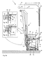
- Figure 1 shows a side view of part of the device 1 according to the invention, which is ready for loading a bin 3.
- the device 1 comprises a casing 5, a lifting mechanism 7, as well as a container 9, which is only shown in part for easy reference, but which of course comprises a space which is closed off from the outside world, in which processed or unprocessed confidential material can be safely stored.
- the upper side of the casing 5 merges with a cover wall 10 of the container 9, as is shown in figure 1 .
- the bin 3 is preferably provided with a locked cover 11, which can only be opened by means of a special tool.
- the bin 3 is further provided with wheels 13 and a handle 15, by means of which a user can move the bin 3.
- the lifting mechanism 7 comprises a loading seat 17, which is provided with a horizontally extendable platform 19, a rear wall 21, as well as a ramp 23.
- the ramp 23 is pivotally connected to the platform 19 and can be pivoted by means of the arms 25 from a first, substantially vertical position to a second position as shown in figure 1 , in which the end 27 of the ramp 23 remote from the platform 19 is supported on the floor surface 29.
- the loading seat 17 further comprises a bin clamp 31, which can be moved by means of telescopic and pivotable arms 33, 35 from a first position, in which the arms 33, 35 and the bin clamp 31 extend upwards at an acute angle with the vertical, so that the bin 3 can be positioned under the arms 33, 35 and the bin clamp 31 in the loading seat 17 without impediment, to a second position, in which the arms 33, 35 and the bin clamp 31 extend around the bin 3 (see figures 2a , 3 and 4 ).
- the lifting mechanism 7 further comprises a lifting frame 36 (indicated by the dotted line), which can be moved upwards and downwards at an acute angle with the vertical by means of two laterally disposed lifting cylinders along two, likewise laterally disposed slide tracks 38.
- the loading seat 17 is pivotally connected to the lifting frame 36 about an axis 37, about which axis 37 the loading seat 17 can be tilted by means of a tilting mechanism, in such a manner that the bin 3, which is already open at that point, can be emptied into the container 9.
- the height h and the width (not shown) of the casing 5 are identical to the height and width of the container 9.
- the casing 5 with the lifting mechanism 7 present therein has a relatively limited length I, preferably maximally 1.15 m. In most cases the preferred length I of the casing 5 is about 1 metre.
- the casing is further provided with a hatch 41, which can be moved from a closed position to an open position (shown in figure 1 ) by means of an electric motor 43, via a chain 47 passed over a pulley 45, thereby providing an opening 49 through which the bin 3 can be moved in the direction indicated by arrow P1.
- Figure 2a shows a side view of part of the device 1 according to the invention while a bin 3 is being loaded, whilst the two larger-scale side views of figures 2b and 2c show the unlocking and the opening of the bin 3.
- a lock 52 must first be unlocked. Only then can the cover 11 be lifted.
- Figures 2b and 2c show an unlocking mechanism 51 for the lock 52, by means of which the cover 11, which is secured against being opened undesirably, can be unlocked and be opened.
- the lock 52 comprises a catch 55, which catch 55 normally hooks behind a projection (not shown) in the closed condition, so that the cover 11 cannot be opened. This projection can be moved by means of a magnet present in the lock 52.
- the unlocking mechanism 51 comprises a lock stamp 53, which can be pneumatically moved onto a contact strip 56 of the lock 52 in the direction indicated by the arrow P1.
- a specific voltage By supplying a specific voltage by means of the lock stamp 53 positioned against the contact strip 56, the magnet (not shown) in the lock 52 is activated, as a result of which the projection is moved or tilted and the catch 55 is no longer blocked.
- the cover 11 can be lifted.
- the unlocking mechanism 51 is further provided with a cover lifter 65, which is pivotable about an axis 63.
- the cover lifter 65 can be moved into abutment with an edge 67 of the cover 11, so that it can lift the cover 11 via the edge 67, as is shown in figure 2c .
- Figure 3 is a side view of part of the device 1 according to the invention, which shows the lifting of the bin 3.
- the bin clamp 31 has been moved by means of the arms 33, 35 from the intermediate position shown in figure 2a to a position in which it extends around the bin 3, in such a manner even that the bin 3 is pressed firmly against the rear wall 21 of the loading seat 17 by means of the bin clamp 31.
- the lifting frame 36, together with the loading seat 17 and the bin 3 held therein, has already been slightly moved in vertical direction.
- the hatch 41 is now in the closed, second position. Furthermore it is apparent from the figure that the cover 11 is already partially lifted by means of the lifting device 63 of the unlocking mechanism 51.
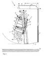
- Figure 4 is a side view of part of the device 1 according to the invention, showing the emptying of a bin 3, in which the loading seat 17 has tilted about the axis 37, so that the cover 11 will swing open further under the influence of the force of gravity and the confidential contents 100 of the bin 3 are emptied into the container 9.
- the operation of the device 1 according to the present invention is as follows:
- the operator opens a box for controlling the device 1 with a key.
- opening the hatch 41 which, together with the casing 5, closes the lifting mechanism 7 (the hatch moves to the upper position), an opening 49 is provided, which opening provides access to the lifting mechanism 7.
- the ramp 23 is folded out simultaneously with the opening of the hatch 41. These operations may also be carried out sequentially, however.
- An automatic detection device in the form of at least one proximity switch (not shown) is incorporated in the device, which proximity switch detects what type of bin is being loaded. After said detection of the type of bin, the loading seat 17 of the device 1 is automatically adapted to the dimension(s) of the bin(s) 3 by means of the arms 33, 35, the ramp 23 and the extendable platform 19.
- the ramp 23 will retract. Preferably, it was folded out against spring pressure (as explained hereinafter). Following that, the platform 19 is retracted and the lower part of the bin 3 is pulled firmly against the rear wall 21.
- the bin clamp 31 is moved from the first position ( figure 1 ), possibly via an intermediate position ( figure 2a ), to a second position ( figure 3 ) by means of the arms 33, 35, and the upper side of the bin 3 is pressed firmly against the rear wall 21. Simultaneously therewith, the hatch 41 can be closed, as is shown in figure 3 .
- the unlocking mechanism(s) 51 provided with the cover lifter(s) 65 is (are) actuated.
- the control of the device 1 lifts the load seat 17 to a tipping position ( figure 4 ).
- the space for the pivoting path of the bin 3 from the loading position ( figure 2a ) to the tipping position ( figure 4 ) is limited, because the bin 3 retained in the loading seat 17 is directly tilted about the axis 37 in the direction of the container 9 while being lifted.
- the lifting mechanism 7 may be provided with vibrating means, so that material 100 that is stuck in the bin 3 is vibrated loose and will fall into the container yet under the influence of the force of gravity.
- the loading seat is pivoted back about the axis 37, with the loading seat 17 being maintained in a straight position until it has landed on the ground.
- the hatch 41 is opened by the electric motor (the hatch moves upward).
- the material from the bin 3 lands in a trough of the container 9 and must be compressed in the container 9 during the loading cycle.
- the compression mechanism (not shown) mounted in the container 9 carries out a compression cycle. This process preferably takes place while the bin 3 is being "lowered".
- FIG. 5a-c A special preferred embodiment of the loading seat 17 of the device 1 according to the invention is partially shown in figures 5a-c .
- the loading seat 17 is shown in a position of rest, in which the ramp 23 extends substantially vertically and the platform 19 is fully retracted.
- the loading seat 17 is further provided with a spring 101, which is connected to the platform 19 with a first end 103 and which is connected to the ramp 23 with a second end 105.
- the ramp 23 further comprises a pressure roller 109, which is movable along a guide 111 of the loading seat 17 in a direction indicated by arrow P1.
- Figure 5b shows the situation when a second part 113 of the arm 24 telescopes out of a first part 115 of the arm 25, which telescoping takes place in the direction indicated by arrow P2.
- the platform 19 is extended in a horizontal direction indicated by arrow P1.
- the pressure roller 109 moves substantially horizontally along the guide 111 in the direction indicated by arrow P1, which guide 111 ends at a specific point, from where the ramp 23 can start pivoting about an axis 117 in the direction indicated by arrow P3.
- Figure 5c shows how the ramp 23 has been tilted against the spring pressure of the spring 101 from the substantially vertical position shown in figure 5b towards the floor surface 29.
- the spring pressure of the spring 101 ensures that the ramp 23 is gradually tilted about the axis 117, so that the end 27 of the ramp 23 will not be damaged and touch the floor surface 29 "softly”.
- the second part 113 of the arm 25 is retracted into the first part 115 in the opposite direction of the arrow P2, causing the ramp 23 to pivot back in the opposite direction of the arrow P3 about the axis 117, from the position shown in figure 5c to the position shown in figure 5b .
- the pressure roller 109 is moved along the guide 111 in the opposite direction of the arrow P1 as a result of the second part 113 being retracted further into the second part 115 of the arm 25, and the platform 19 is likewise retracted in the opposite direction of the arrow P1; the extent to which the pressure roller 109 and the platform 19 are moved to the position of the pressure roller 109 and the platform 19 as shown in figure 5a will depend on the dimension of the loaded bin 3.
- the platform 19 and the pressure roller 109 are in any case moved so far that the loaded bin 3 is clamped firmly between the ramp 23 and the rear wall 21 of the loading seat 17 for carrying out the above-described steps of opening the lock 52 of the bin 3 and emptying the bin 3.
- the spring pressure of the spring 101 moreover causes the ramp 23 to be locked in its vertical position.
- Such a loading seat 17 makes it possible to load a bin 3 in a quick and reliable manner.
- the total amount of time required for carrying out the method of loading the bin 3 by means of the loading seat 17, emptying the same by means of the lifting mechanism and unloading it again is less than 1 minute.
- two or more bins may be emptied simultaneously by means of the device according to the present invention.
Landscapes
- Engineering & Computer Science (AREA)
- Mechanical Engineering (AREA)
- Control And Other Processes For Unpacking Of Materials (AREA)
- Details Of Rigid Or Semi-Rigid Containers (AREA)
- Refuse Receptacles (AREA)
Abstract
Description
- The invention relates to a device for storing and/or processing confidential material, which device comprises a substantially longitudinally extending container, in which the material is to be stored, and a lifting mechanism, by means of which a bin containing confidential material can be emptied, which lifting mechanism is enclosed in a casing.
- Such a device, which is mounted on a truck, is known from
US-6,588,691 . The known device likewise comprises a longitudinally extending container, which is indicated at 5 infigure 2 of said US patent. In said container, the confidential contents of the bins emptied by means of the lifting mechanism are stored. The known device is further provided with an extendable casing. A space is present between the casing and the lifting mechanism, in which space a bin, screened from the outside environment, is vertically movable and tiltable. - Such a casing is required when emptying such bins containing confidential material, and ensures that the confidential material will not be visible from outside when the bins are being emptied. Furthermore, the casing prevents confidential material being blown away.
- A drawback of this known device is that a special configuration of the device is required due to the lateral entry of the bin into the container. In addition, because of the extendable casing of the known device, it takes relatively a long time before the device is ready for operation.
- It is an object of the present invention to provide a device for storing and/or processing confidential material which has an efficient configuration.
- This object is accomplished with the device according to the present invention in that the lifting mechanism provided with the casing is mounted on one of the two ends extending in the longitudinal direction of the container.
- Mounting the lifting mechanism provided with the fixed casing to one of the two ends extending in the longitudinal direction of the container makes it possible to empty a bin quickly into the container by means of the lifting mechanism, with the container forming the greater part of the volume of the device. The width of the device is furthermore constant at all times. A major advantage of the device according to the present invention is the improved configuration, so that the container of the device according to the present invention will have a larger volume than the known device, whilst the overall dimension of the device according to the invention is substantially the same as that of the known device. Preferably, the lifting mechanism provided with the casing extends over substantially the entire end of the container.
- The term "confidential material" refers to information carriers such as confidential documents, archive material and other confidential paper waste, but also floppy disks and memory sticks.
- In the container, the material may be compressed, if desired, thereby increasing the density of the stored material in the container.
- One embodiment of the device according to the invention is characterised in that the bin in which the confidential material is stored is locked, in which case the lifting mechanism is provided with an unlocking mechanism for unlocking the locked bin.
- It is known per se to provide bins with a relatively small opening, which is for example provided with a flap to be opened against spring force, through which the confidential material can be deposited into the bin. Once the confidential material has been deposited into the bin, removing said material from the bin through said small opening is difficult if not impossible. Furthermore, such bins are provided with a cover or a bottom which can be opened by means of a special tool for emptying the bin. With the device according to the present invention, the bin positioned in the lifting mechanism, which is preferably fully enclosed in the casing, can be unlocked by means of the unlocking mechanism for emptying the bin, so that even the operator of the device is unable to see or contact the contents of the bin. By having access to the confidential material by unlocking and opening the bin take place in a space closed off by the casing, improper use of the confidential material can be prevented. Preferably, the bin is closed off by the casing in such a manner that at least the opened part of the bin is closed off from the outside world by means of the casing. This means that the casing need not fully enclose the bin, but that it must at least enclose the part of the bin that is to be opened.
- The bin is preferably movable by means of wheels, so that the operator can push the bin into the lifting mechanism.
- Another embodiment of the device according to the invention is characterised in that the casing is provided with a hatch, via which hatch, when opened, the bin can be moved into the lifting mechanism, after which the bin positioned in the lifting mechanism is at least partially closed off from the outside world by the casing by closing the hatch therein.
- Via such a hatch, which can be operated by means of an electric motor, for example, the bin can be quickly placed into the lifting mechanism, after which the bin can be unlocked by means of the unlocking mechanism in the closed position of the hatch for emptying the bin.
- Yet another embodiment of the device according to the invention is characterised in that the lifting mechanism comprises a loading seat provided with a platform, to which a pivotable ramp is connected, and with a rear wall, by means of which pivotable ramp the bin, once it has been positioned on the platform, can be fixed in position between the rear wall and the ramp.
- At least the lower part of the bin can be firmly secured by means of such a loading seat. The pivotable ramp can be pivoted from a first, preferably vertically extending position, to a second position, in which the end of the ramp opposite the end connected to the platform rests on a floor surface, so that the bin, which is provided with wheels, can be positioned from the floor surface onto the platform via the ramp. Once the ramp is positioned on the platform, the ramp can return from the second position to the first position. The platform is so dimensioned that the bin is clamped between the ramp in first position thereof and the rear wall. In this way movement of the movable bin is no longer possible anyhow.
- Yet another embodiment of the device according to the invention is characterised in that the platform is extendable substantially in horizontal direction.
- In this way the platform can be adapted to the dimensions of various bins. The ramp is preferably connected to the extendable end of the platform, making it possible for an operator upon extension of the platform in horizontal direction to position the bin just within the casing without having to enter the casing himself. Furthermore, the bin can be clamped more firmly between the rear wall and the ramp as a result of the platform being retracted. The loading seat is provided with at least one arm, by means of which the ramp can be folded out and be retracted, and by means of which the platform can be extended and retracted. In this way the ramp and the platform can be quickly extended and retracted, and that in an energetically advantageous manner. The time required for loading a bin into the lifting mechanism is significantly reduced by using such a loading seat.
- Another embodiment of the device according to the invention is characterised in that the lifting mechanism is further provided with a bin clamp, which can be moved from a first position, in which it extends above the bin, to a second position, in which it extends around the bin, in which second position the bin can be clamped down between the rear wall and the bin clamp.
- The bin is firmly clamped down by means of such a bin clamp, so that the bin can undergo the required tilting movement for being emptied. When the bin clamp is in the first position, the bin can be loaded into the loading seat in a simple manner.
- Yet another embodiment of the device according to the invention is characterised in that the container comprises a width (B) extending transversely to the longitudinal direction and a height (H), with the width (b) and the height (h) of the casing enclosing the lifting mechanism being substantially identical to the width (B) and a height (H) of the container, and the length (I) of the casing maximally equalling two-thirds the width (B) of the container, preferably being about 1 metre.
- When a container having such dimensions and comprising a lifting mechanism and a casing is used, it is even possible to empty several bins simultaneously, depending on the dimension of said bins. Furthermore, it is possible when using the device according to the present invention to empty much wider bins than is possible with the device known from the above-described US patent. A major advantage of the present invention is the fact that the lift and the casing take up very little space in longitudinal direction, so that the dimensions of the device are mainly determined by the container. This is advantageous in particular in the case of a device which is disposed on a truck, for example, because the total length of the truck is thus reduced, without this being realised at the expense of the storage capacity in the container.
- Yet another embodiment of the device according to the invention is characterised in that the bin can be moved upwards by means of the lifting mechanism, during which upward movement the bin can be tilted by means of a tilting mechanism of the lifting mechanism.
- Since the upper side of the bin is tilted in the direction of the container while the bin is being lifted, the space for the pivoting path of the bin is limited, so that a limited amount of space is required between the container and the casing. Preferably, the length of the casing is about 1 metre, as indicated above.
- Yet another embodiment of the device according to the invention is characterised in that the bin can be tilted through an angle of 90-180 degrees, preferably through an angle of 110-170 degrees, by means of the tilting mechanism.
- The minimum angle required for emptying the bin is 90 degrees. If the influence of the force of gravity upon emptying of the bin needs to be greater however, it is preferable to use a larger angle. The influence of the force of gravity is greatest if the bin is tilted through 180 degrees. In practice it has been found that the influence of the force of gravity suffices for completely emptying the bin if said angle ranges between 110 and 170 degrees.
- Yet another embodiment of the device according to the invention is characterised in that the device is removably or fixedly mounted on a truck or a trailer.
- In this way the device can be transported on a truck and/or a trailer to offices or factories where the bins are filled with confidential material. Periodically, a truck and/or a trailer can come around for emptying the bins. It is also possible to mount the device on a trailer which remains at the premises of the factory at the office, so that bins can be emptied all the time. It is also possible to construct a device which can be unloaded from a truck just like a sea container, so that the device can be left at a premises. Once the container is full, it is collected by a truck, so that the full container can be emptied for further destruction of its contents or storage in a warehouse and can be used again, if necessary. In this way, several devices can be delivered/collected by means of a truck in one day. The device may furthermore be provided with a detection means which detects the degree of filling of the container, and also with a communication means which can communicate to a centre that the device is full and needs to be collected.
- The invention will now be explained with reference to the appended figures, in which:
-
Figure 1 is a side view of part of the device according to the invention, which is ready for loading a bin; -
Figure 2a is a side view of part of the device according to the invention during the loading of the bin, andfigures 2b and 2b are larger-scale side views, showing the unlocking and opening of a bin; -
Figure 3 is a side view of part of the device according to the invention, showing the lifting of a bin; -
Figure 4 is a side view of part of the device according to the invention, showing the emptying of a bin; -
Figures 5a-c are side views of part of the loading seat, showing the operation of this part of the loading seat. - Like parts are indicated by the same numerals in the various figures.
-
Figure 1 shows a side view of part of thedevice 1 according to the invention, which is ready for loading abin 3. - The
device 1 comprises acasing 5, alifting mechanism 7, as well as acontainer 9, which is only shown in part for easy reference, but which of course comprises a space which is closed off from the outside world, in which processed or unprocessed confidential material can be safely stored. - The upper side of the
casing 5 merges with acover wall 10 of thecontainer 9, as is shown infigure 1 . - The
bin 3 is preferably provided with a lockedcover 11, which can only be opened by means of a special tool. Thebin 3 is further provided withwheels 13 and ahandle 15, by means of which a user can move thebin 3. - The
lifting mechanism 7 comprises aloading seat 17, which is provided with a horizontallyextendable platform 19, arear wall 21, as well as aramp 23. Theramp 23 is pivotally connected to theplatform 19 and can be pivoted by means of thearms 25 from a first, substantially vertical position to a second position as shown infigure 1 , in which theend 27 of theramp 23 remote from theplatform 19 is supported on thefloor surface 29. - The
loading seat 17 further comprises abin clamp 31, which can be moved by means of telescopic andpivotable arms arms bin clamp 31 extend upwards at an acute angle with the vertical, so that thebin 3 can be positioned under thearms bin clamp 31 in theloading seat 17 without impediment, to a second position, in which thearms bin clamp 31 extend around the bin 3 (seefigures 2a ,3 and4 ). - The
lifting mechanism 7 further comprises a lifting frame 36 (indicated by the dotted line), which can be moved upwards and downwards at an acute angle with the vertical by means of two laterally disposed lifting cylinders along two, likewise laterally disposed slide tracks 38. Theloading seat 17 is pivotally connected to the liftingframe 36 about anaxis 37, about whichaxis 37 theloading seat 17 can be tilted by means of a tilting mechanism, in such a manner that thebin 3, which is already open at that point, can be emptied into thecontainer 9. - The height h and the width (not shown) of the
casing 5 are identical to the height and width of thecontainer 9. Thecasing 5 with thelifting mechanism 7 present therein has a relatively limited length I, preferably maximally 1.15 m. In most cases the preferred length I of thecasing 5 is about 1 metre. - The casing is further provided with a
hatch 41, which can be moved from a closed position to an open position (shown infigure 1 ) by means of anelectric motor 43, via achain 47 passed over apulley 45, thereby providing anopening 49 through which thebin 3 can be moved in the direction indicated by arrow P1. -
Figure 2a shows a side view of part of thedevice 1 according to the invention while abin 3 is being loaded, whilst the two larger-scale side views offigures 2b and 2c show the unlocking and the opening of thebin 3. - An operator has positioned the
bin 3 shown infigure 2a on theloading seat 17 by means of theramp 23, and subsequently theramp 23 has been moved to the first position. Furthermore, theplatform 19 has been retracted. Theplatform 19 and theramp 23 firmly press thewheels 13 of thebin 3 against therear wall 21 of theloading seat 17. Thearms bin clamp 31 have tilted from the first position shown infigure 1 to an intermediate position as shown infigure 2 . - To empty the
bin 3, alock 52 must first be unlocked. Only then can thecover 11 be lifted. -
Figures 2b and 2c show an unlockingmechanism 51 for thelock 52, by means of which thecover 11, which is secured against being opened undesirably, can be unlocked and be opened. Thelock 52 comprises acatch 55, which catch 55 normally hooks behind a projection (not shown) in the closed condition, so that thecover 11 cannot be opened. This projection can be moved by means of a magnet present in thelock 52. - The unlocking
mechanism 51 comprises alock stamp 53, which can be pneumatically moved onto acontact strip 56 of thelock 52 in the direction indicated by the arrow P1. By supplying a specific voltage by means of thelock stamp 53 positioned against thecontact strip 56, the magnet (not shown) in thelock 52 is activated, as a result of which the projection is moved or tilted and thecatch 55 is no longer blocked. When thecatch 55 is no longer blocked, thecover 11 can be lifted. - The unlocking
mechanism 51 is further provided with acover lifter 65, which is pivotable about anaxis 63. When thelock 52 is opened, thecover lifter 65 can be moved into abutment with anedge 67 of thecover 11, so that it can lift thecover 11 via theedge 67, as is shown infigure 2c . -
Figure 3 is a side view of part of thedevice 1 according to the invention, which shows the lifting of thebin 3. Thebin clamp 31 has been moved by means of thearms figure 2a to a position in which it extends around thebin 3, in such a manner even that thebin 3 is pressed firmly against therear wall 21 of theloading seat 17 by means of thebin clamp 31. The liftingframe 36, together with theloading seat 17 and thebin 3 held therein, has already been slightly moved in vertical direction. Thehatch 41 is now in the closed, second position. Furthermore it is apparent from the figure that thecover 11 is already partially lifted by means of thelifting device 63 of the unlockingmechanism 51. -
Figure 4 is a side view of part of thedevice 1 according to the invention, showing the emptying of abin 3, in which theloading seat 17 has tilted about theaxis 37, so that thecover 11 will swing open further under the influence of the force of gravity and theconfidential contents 100 of thebin 3 are emptied into thecontainer 9. - The operation of the
device 1 according to the present invention is as follows: - The operator opens a box for controlling the
device 1 with a key. By opening thehatch 41 which, together with thecasing 5, closes the lifting mechanism 7 (the hatch moves to the upper position), anopening 49 is provided, which opening provides access to thelifting mechanism 7. - Preferably, the
ramp 23 is folded out simultaneously with the opening of thehatch 41. These operations may also be carried out sequentially, however. - An automatic detection device in the form of at least one proximity switch (not shown) is incorporated in the device, which proximity switch detects what type of bin is being loaded. After said detection of the type of bin, the
loading seat 17 of thedevice 1 is automatically adapted to the dimension(s) of the bin(s) 3 by means of thearms ramp 23 and theextendable platform 19. - The operator then takes hold of the
bin 3, moves it over theramp 23 and into the device via theopening 49 and positions it in theloading seat 17. - First, the
ramp 23 will retract. Preferably, it was folded out against spring pressure (as explained hereinafter). Following that, theplatform 19 is retracted and the lower part of thebin 3 is pulled firmly against therear wall 21. Thebin clamp 31 is moved from the first position (figure 1 ), possibly via an intermediate position (figure 2a ), to a second position (figure 3 ) by means of thearms bin 3 is pressed firmly against therear wall 21. Simultaneously therewith, thehatch 41 can be closed, as is shown infigure 3 . - Immediately after the
hatch 41 has been closed, the unlocking mechanism(s) 51 provided with the cover lifter(s) 65 is (are) actuated. - After the
cover 11 of thebin 3 has been opened, the control of thedevice 1 lifts theload seat 17 to a tipping position (figure 4 ). The space for the pivoting path of thebin 3 from the loading position (figure 2a ) to the tipping position (figure 4 ) is limited, because thebin 3 retained in theloading seat 17 is directly tilted about theaxis 37 in the direction of thecontainer 9 while being lifted. Thelifting mechanism 7 may be provided with vibrating means, so thatmaterial 100 that is stuck in thebin 3 is vibrated loose and will fall into the container yet under the influence of the force of gravity. - After a brief space of time, the loading seat is pivoted back about the
axis 37, with theloading seat 17 being maintained in a straight position until it has landed on the ground. - Simultaneously with the lowering of the
loading seat 17, thehatch 41 is opened by the electric motor (the hatch moves upward). - At the end of each loading cycle, which ends when the emptied
bin 3 can be wheeled out of theloading seat 17, the operator has a possibility to position theloading seat 17 in a driving position. Theloading seat 17 is to that end lifted to a "tipping position" (figure 4 ). In order to do so, the actions "clamp bin", "close hatch" and "lift" are automatically completed in succession. A hydraulically actuated non-return valve (not shown) causes theloading seat 17 to remain at this position. Theloading seat 17 cannot tip on account of its own weight when the tilting motor has no power or during a hydraulic pressure drop. - The material from the
bin 3 lands in a trough of thecontainer 9 and must be compressed in thecontainer 9 during the loading cycle. The compression mechanism (not shown) mounted in thecontainer 9 carries out a compression cycle. This process preferably takes place while thebin 3 is being "lowered". - A special preferred embodiment of the
loading seat 17 of thedevice 1 according to the invention is partially shown infigures 5a-c . - In
figure 5a theloading seat 17 is shown in a position of rest, in which theramp 23 extends substantially vertically and theplatform 19 is fully retracted. Theloading seat 17 is further provided with aspring 101, which is connected to theplatform 19 with afirst end 103 and which is connected to theramp 23 with asecond end 105. - The
arm 25, preferably two arms are provided on either side of the loading seat, is pivotally connected to afixed part 107 of theloading seat 17 and to theramp 23. - The
ramp 23 further comprises apressure roller 109, which is movable along aguide 111 of theloading seat 17 in a direction indicated by arrow P1. -
Figure 5b shows the situation when asecond part 113 of the arm 24 telescopes out of afirst part 115 of thearm 25, which telescoping takes place in the direction indicated by arrow P2. As a result of said telescoping of thearm 25, theplatform 19 is extended in a horizontal direction indicated by arrow P1. At the same time, thepressure roller 109 moves substantially horizontally along theguide 111 in the direction indicated by arrow P1, which guide 111 ends at a specific point, from where theramp 23 can start pivoting about anaxis 117 in the direction indicated by arrow P3. -
Figure 5c shows how theramp 23 has been tilted against the spring pressure of thespring 101 from the substantially vertical position shown infigure 5b towards thefloor surface 29. The spring pressure of thespring 101 ensures that theramp 23 is gradually tilted about theaxis 117, so that theend 27 of theramp 23 will not be damaged and touch thefloor surface 29 "softly". - Once a
bin 3 has been loaded, thesecond part 113 of thearm 25 is retracted into thefirst part 115 in the opposite direction of the arrow P2, causing theramp 23 to pivot back in the opposite direction of the arrow P3 about theaxis 117, from the position shown infigure 5c to the position shown infigure 5b . From the position shown infigure 5b , thepressure roller 109 is moved along theguide 111 in the opposite direction of the arrow P1 as a result of thesecond part 113 being retracted further into thesecond part 115 of thearm 25, and theplatform 19 is likewise retracted in the opposite direction of the arrow P1; the extent to which thepressure roller 109 and theplatform 19 are moved to the position of thepressure roller 109 and theplatform 19 as shown infigure 5a will depend on the dimension of the loadedbin 3. Theplatform 19 and thepressure roller 109 are in any case moved so far that the loadedbin 3 is clamped firmly between theramp 23 and therear wall 21 of theloading seat 17 for carrying out the above-described steps of opening thelock 52 of thebin 3 and emptying thebin 3. The spring pressure of thespring 101 moreover causes theramp 23 to be locked in its vertical position. - By means of this construction, three functions are carried out by operating a single, for example
hydraulic arm 25, viz extending theplatform 19, building theramp 23 about theaxis 117 and locking theramp 23 in its vertical position. - Such a
loading seat 17 makes it possible to load abin 3 in a quick and reliable manner. - The total amount of time required for carrying out the method of loading the
bin 3 by means of theloading seat 17, emptying the same by means of the lifting mechanism and unloading it again is less than 1 minute. - Instead of unlocking the upper side of the
cover 11 of thebin 3, it is also possible to unlock the bottom of thebin 3. This manner of emptying will require a different pivoting path for emptying thebin 3, however. - Depending on the dimensions of the bins, two or more bins may be emptied simultaneously by means of the device according to the present invention.
- In addition to or instead of compressing the confidential material in the
container 9 it is also possible to shred said material.
Claims (10)
- A device for storing or processing confidential material, which device comprises a substantially longitudinally extending container, in which the material is to be stored, which device comprises a lifting mechanism, by means of which a bin containing confidential material can be emptied, which lifting mechanism is enclosed in a casing, characterised in that the lifting mechanism provided with the casing is mounted on one of the two ends extending in the longitudinal direction of the container.
- A device according to claim 1, characterised in that the bin in which the confidential material is stored is locked, and that the lifting mechanism is provided with an unlocking mechanism for unlocking the locked bin.
- A device according to any one of the preceding claims, characterised in that the casing is provided with a hatch, via which hatch, when opened, the bin can be moved into the lifting mechanism, after which the bin positioned in the lifting mechanism is at least partially closed off from the outside world by the casing by closing the hatch therein.
- A device according to any one of the preceding claims, characterised in that the lifting mechanism comprises a loading seat provided with a platform, to which a pivotable ramp is connected, and with a rear wall, by means of which pivotable ramp the bin, once it has been positioned on the platform, can be fixed in position between the rear wall and the ramp.
- A device according to claim 4, characterised in that the platform is extendable substantially in horizontal direction.
- A device according to any one of the preceding claims, characterised in that the lifting mechanism is further provided with a bin clamp, which is movable from a first, higher position relative to the bin to a second position, in which it extends around the bin, in which second position the bin can be clamped down between the rear wall and the bin clamp.
- A device according to any one of the preceding claims, characterised in that the container comprises a width (B) extending transversely to the longitudinal direction and a height (H), with the width (b) and the height (h) of the casing enclosing the lifting mechanism being substantially identical to the width (B) and a height (H) of the container, and the length (I) of the casing maximally equalling two-thirds the width (B) of the container, preferably being about 1 metre.
- A device according to any one of the preceding claims, characterised in that the bin can be moved upwards by means of the lifting mechanism, during which upward movement the bin can be tilted by means of a tilting mechanism of the lifting mechanism.
- A device according to any one of the preceding claims, characterised in that the bin can be tilted through an angle of 90-180 degrees, preferably through an angle of 110-170 degrees, by means of the tilting mechanism.
- A device according to any one of the preceding claims, characterised in that the device is removably or fixedly mounted on a truck or a trailer.
Priority Applications (1)
| Application Number | Priority Date | Filing Date | Title |
|---|---|---|---|
| PL08075894T PL2067720T3 (en) | 2007-12-03 | 2008-11-21 | Device for storing and/or processing confidential material |
Applications Claiming Priority (1)
| Application Number | Priority Date | Filing Date | Title |
|---|---|---|---|
| NL1034785A NL1034785C2 (en) | 2007-12-03 | 2007-12-03 | Device for storing and / or processing confidential material. |
Publications (2)
| Publication Number | Publication Date |
|---|---|
| EP2067720A1 true EP2067720A1 (en) | 2009-06-10 |
| EP2067720B1 EP2067720B1 (en) | 2017-01-04 |
Family
ID=39509639
Family Applications (1)
| Application Number | Title | Priority Date | Filing Date |
|---|---|---|---|
| EP08075894.9A Active EP2067720B1 (en) | 2007-12-03 | 2008-11-21 | Device for storing and/or processing confidential material |
Country Status (4)
| Country | Link |
|---|---|
| EP (1) | EP2067720B1 (en) |
| ES (1) | ES2620741T3 (en) |
| NL (1) | NL1034785C2 (en) |
| PL (1) | PL2067720T3 (en) |
Cited By (3)
| Publication number | Priority date | Publication date | Assignee | Title |
|---|---|---|---|---|
| NL2010344C2 (en) * | 2013-02-22 | 2014-08-25 | Schijndel Holding B V Van | DEVICE AND METHOD FOR PROCESSING CONFIDENTIAL MATERIAL. |
| WO2017150972A1 (en) | 2016-03-02 | 2017-09-08 | Van Schijndel Holding B.V. | Device and system for processing confidential material |
| US20250282552A1 (en) * | 2024-03-07 | 2025-09-11 | Southworth International Group, Inc. | Container unloading apparatus |
Citations (5)
| Publication number | Priority date | Publication date | Assignee | Title |
|---|---|---|---|---|
| DE10208383C1 (en) | 2002-02-27 | 2003-02-27 | Hansjoerg Huber | Document and data carrier collection, transport and secure disposal method includes tracking of collected material at all points between collection and disposal |
| US6588691B2 (en) | 2001-08-31 | 2003-07-08 | Shred-Tech Inc. | Mobile document shredder with retractable loading tunnel and load cell |
| NL1023248C2 (en) * | 2003-04-23 | 2004-10-27 | Bekker L J Holding | Bin emptying device for refuse collection vehicle, uses endless vertical chain with bin locating parts to pick up bin and move it into emptying position |
| US20050017106A1 (en) * | 2003-07-23 | 2005-01-27 | Rajewski Robert C. | Paper shredder |
| US20060032957A1 (en) * | 2004-08-13 | 2006-02-16 | Vecoplan, Llc | Mobile shredder |
-
2007
- 2007-12-03 NL NL1034785A patent/NL1034785C2/en active Search and Examination
-
2008
- 2008-11-21 ES ES08075894.9T patent/ES2620741T3/en active Active
- 2008-11-21 EP EP08075894.9A patent/EP2067720B1/en active Active
- 2008-11-21 PL PL08075894T patent/PL2067720T3/en unknown
Patent Citations (5)
| Publication number | Priority date | Publication date | Assignee | Title |
|---|---|---|---|---|
| US6588691B2 (en) | 2001-08-31 | 2003-07-08 | Shred-Tech Inc. | Mobile document shredder with retractable loading tunnel and load cell |
| DE10208383C1 (en) | 2002-02-27 | 2003-02-27 | Hansjoerg Huber | Document and data carrier collection, transport and secure disposal method includes tracking of collected material at all points between collection and disposal |
| NL1023248C2 (en) * | 2003-04-23 | 2004-10-27 | Bekker L J Holding | Bin emptying device for refuse collection vehicle, uses endless vertical chain with bin locating parts to pick up bin and move it into emptying position |
| US20050017106A1 (en) * | 2003-07-23 | 2005-01-27 | Rajewski Robert C. | Paper shredder |
| US20060032957A1 (en) * | 2004-08-13 | 2006-02-16 | Vecoplan, Llc | Mobile shredder |
Cited By (4)
| Publication number | Priority date | Publication date | Assignee | Title |
|---|---|---|---|---|
| NL2010344C2 (en) * | 2013-02-22 | 2014-08-25 | Schijndel Holding B V Van | DEVICE AND METHOD FOR PROCESSING CONFIDENTIAL MATERIAL. |
| EP2769934A1 (en) * | 2013-02-22 | 2014-08-27 | Van Schijndel Holding B.V. | Device and method for processing confidential material |
| WO2017150972A1 (en) | 2016-03-02 | 2017-09-08 | Van Schijndel Holding B.V. | Device and system for processing confidential material |
| US20250282552A1 (en) * | 2024-03-07 | 2025-09-11 | Southworth International Group, Inc. | Container unloading apparatus |
Also Published As
| Publication number | Publication date |
|---|---|
| PL2067720T3 (en) | 2017-07-31 |
| EP2067720B1 (en) | 2017-01-04 |
| NL1034785C2 (en) | 2009-06-04 |
| ES2620741T3 (en) | 2017-06-29 |
Similar Documents
| Publication | Publication Date | Title |
|---|---|---|
| US4552500A (en) | Refuse hauling and storage apparatus | |
| US9598235B2 (en) | Motor vehicle for collecting and sorting material and method of doing same | |
| US4363588A (en) | Refuse handling system | |
| US4470747A (en) | Separated discards carrier with safety features | |
| KR101981268B1 (en) | Food waste collecting vehicle | |
| WO2001056775A1 (en) | Baling apparatus and method | |
| EP2067720B1 (en) | Device for storing and/or processing confidential material | |
| US6752467B1 (en) | Vacuum truck dump container apparatus | |
| JP4307447B2 (en) | Equipment for collecting, compressing and bagging municipal waste | |
| CA1264702A (en) | Recyclable refuse collecting and transport vehicle with side bucket top loading | |
| US5632199A (en) | Compactor | |
| US10611566B1 (en) | Side loading garbage truck with full eject mechanism | |
| US3828956A (en) | Ejection apparatus and method for emptying refuse containers | |
| US6012891A (en) | Parts handling apparatus | |
| CN101495360B (en) | mechanical tailgate | |
| US7077060B2 (en) | Container for compacting paper waste | |
| CN110615215B (en) | Buried garbage compression equipment and garbage compression method | |
| US10525648B2 (en) | Method and device for compacting materials | |
| WO1993022227A1 (en) | Refuse collection apparatus | |
| US2406015A (en) | Refuse body | |
| US8528769B1 (en) | Lifter apparatus and method | |
| US8033774B2 (en) | Secure rear-loading material handling apparatus system | |
| EP0636556A1 (en) | Refuse handling system | |
| SU1101386A1 (en) | Refuse carrier | |
| EP4180358B1 (en) | Underground waste collecting system |
Legal Events
| Date | Code | Title | Description |
|---|---|---|---|
| PUAI | Public reference made under article 153(3) epc to a published international application that has entered the european phase |
Free format text: ORIGINAL CODE: 0009012 |
|
| AK | Designated contracting states |
Kind code of ref document: A1 Designated state(s): AT BE BG CH CY CZ DE DK EE ES FI FR GB GR HR HU IE IS IT LI LT LU LV MC MT NL NO PL PT RO SE SI SK TR |
|
| AX | Request for extension of the european patent |
Extension state: AL BA MK RS |
|
| 17P | Request for examination filed |
Effective date: 20091111 |
|
| 17Q | First examination report despatched |
Effective date: 20100121 |
|
| AKX | Designation fees paid |
Designated state(s): AT BE BG CH CY CZ DE DK EE ES FI FR GB GR HR HU IE IS IT LI LT LU LV MC MT NL NO PL PT RO SE SI SK TR |
|
| GRAP | Despatch of communication of intention to grant a patent |
Free format text: ORIGINAL CODE: EPIDOSNIGR1 |
|
| INTG | Intention to grant announced |
Effective date: 20160530 |
|
| GRAJ | Information related to disapproval of communication of intention to grant by the applicant or resumption of examination proceedings by the epo deleted |
Free format text: ORIGINAL CODE: EPIDOSDIGR1 |
|
| GRAR | Information related to intention to grant a patent recorded |
Free format text: ORIGINAL CODE: EPIDOSNIGR71 |
|
| GRAS | Grant fee paid |
Free format text: ORIGINAL CODE: EPIDOSNIGR3 |
|
| INTC | Intention to grant announced (deleted) | ||
| INTG | Intention to grant announced |
Effective date: 20160909 |
|
| GRAA | (expected) grant |
Free format text: ORIGINAL CODE: 0009210 |
|
| AK | Designated contracting states |
Kind code of ref document: B1 Designated state(s): AT BE BG CH CY CZ DE DK EE ES FI FR GB GR HR HU IE IS IT LI LT LU LV MC MT NL NO PL PT RO SE SI SK TR |
|
| REG | Reference to a national code |
Ref country code: GB Ref legal event code: FG4D |
|
| REG | Reference to a national code |
Ref country code: CH Ref legal event code: EP |
|
| REG | Reference to a national code |
Ref country code: AT Ref legal event code: REF Ref document number: 858999 Country of ref document: AT Kind code of ref document: T Effective date: 20170115 |
|
| REG | Reference to a national code |
Ref country code: IE Ref legal event code: FG4D |
|
| REG | Reference to a national code |
Ref country code: DE Ref legal event code: R096 Ref document number: 602008048198 Country of ref document: DE |
|
| REG | Reference to a national code |
Ref country code: SE Ref legal event code: TRGR |
|
| REG | Reference to a national code |
Ref country code: CH Ref legal event code: NV Representative=s name: DR. LUSUARDI AG, CH |
|
| REG | Reference to a national code |
Ref country code: LT Ref legal event code: MG4D Ref country code: NL Ref legal event code: MP Effective date: 20170104 |
|
| REG | Reference to a national code |
Ref country code: ES Ref legal event code: FG2A Ref document number: 2620741 Country of ref document: ES Kind code of ref document: T3 Effective date: 20170629 |
|
| PG25 | Lapsed in a contracting state [announced via postgrant information from national office to epo] |
Ref country code: NL Free format text: LAPSE BECAUSE OF FAILURE TO SUBMIT A TRANSLATION OF THE DESCRIPTION OR TO PAY THE FEE WITHIN THE PRESCRIBED TIME-LIMIT Effective date: 20170104 |
|
| PG25 | Lapsed in a contracting state [announced via postgrant information from national office to epo] |
Ref country code: NO Free format text: LAPSE BECAUSE OF FAILURE TO SUBMIT A TRANSLATION OF THE DESCRIPTION OR TO PAY THE FEE WITHIN THE PRESCRIBED TIME-LIMIT Effective date: 20170404 Ref country code: LT Free format text: LAPSE BECAUSE OF FAILURE TO SUBMIT A TRANSLATION OF THE DESCRIPTION OR TO PAY THE FEE WITHIN THE PRESCRIBED TIME-LIMIT Effective date: 20170104 Ref country code: GR Free format text: LAPSE BECAUSE OF FAILURE TO SUBMIT A TRANSLATION OF THE DESCRIPTION OR TO PAY THE FEE WITHIN THE PRESCRIBED TIME-LIMIT Effective date: 20170405 Ref country code: IS Free format text: LAPSE BECAUSE OF FAILURE TO SUBMIT A TRANSLATION OF THE DESCRIPTION OR TO PAY THE FEE WITHIN THE PRESCRIBED TIME-LIMIT Effective date: 20170504 Ref country code: HR Free format text: LAPSE BECAUSE OF FAILURE TO SUBMIT A TRANSLATION OF THE DESCRIPTION OR TO PAY THE FEE WITHIN THE PRESCRIBED TIME-LIMIT Effective date: 20170104 |
|
| PG25 | Lapsed in a contracting state [announced via postgrant information from national office to epo] |
Ref country code: PT Free format text: LAPSE BECAUSE OF FAILURE TO SUBMIT A TRANSLATION OF THE DESCRIPTION OR TO PAY THE FEE WITHIN THE PRESCRIBED TIME-LIMIT Effective date: 20170504 Ref country code: LV Free format text: LAPSE BECAUSE OF FAILURE TO SUBMIT A TRANSLATION OF THE DESCRIPTION OR TO PAY THE FEE WITHIN THE PRESCRIBED TIME-LIMIT Effective date: 20170104 Ref country code: BG Free format text: LAPSE BECAUSE OF FAILURE TO SUBMIT A TRANSLATION OF THE DESCRIPTION OR TO PAY THE FEE WITHIN THE PRESCRIBED TIME-LIMIT Effective date: 20170404 |
|
| REG | Reference to a national code |
Ref country code: DE Ref legal event code: R097 Ref document number: 602008048198 Country of ref document: DE |
|
| PG25 | Lapsed in a contracting state [announced via postgrant information from national office to epo] |
Ref country code: CZ Free format text: LAPSE BECAUSE OF FAILURE TO SUBMIT A TRANSLATION OF THE DESCRIPTION OR TO PAY THE FEE WITHIN THE PRESCRIBED TIME-LIMIT Effective date: 20170104 Ref country code: RO Free format text: LAPSE BECAUSE OF FAILURE TO SUBMIT A TRANSLATION OF THE DESCRIPTION OR TO PAY THE FEE WITHIN THE PRESCRIBED TIME-LIMIT Effective date: 20170104 Ref country code: IT Free format text: LAPSE BECAUSE OF FAILURE TO SUBMIT A TRANSLATION OF THE DESCRIPTION OR TO PAY THE FEE WITHIN THE PRESCRIBED TIME-LIMIT Effective date: 20170104 Ref country code: EE Free format text: LAPSE BECAUSE OF FAILURE TO SUBMIT A TRANSLATION OF THE DESCRIPTION OR TO PAY THE FEE WITHIN THE PRESCRIBED TIME-LIMIT Effective date: 20170104 Ref country code: SK Free format text: LAPSE BECAUSE OF FAILURE TO SUBMIT A TRANSLATION OF THE DESCRIPTION OR TO PAY THE FEE WITHIN THE PRESCRIBED TIME-LIMIT Effective date: 20170104 |
|
| PLBE | No opposition filed within time limit |
Free format text: ORIGINAL CODE: 0009261 |
|
| STAA | Information on the status of an ep patent application or granted ep patent |
Free format text: STATUS: NO OPPOSITION FILED WITHIN TIME LIMIT |
|
| REG | Reference to a national code |
Ref country code: FR Ref legal event code: PLFP Year of fee payment: 10 |
|
| PG25 | Lapsed in a contracting state [announced via postgrant information from national office to epo] |
Ref country code: DK Free format text: LAPSE BECAUSE OF FAILURE TO SUBMIT A TRANSLATION OF THE DESCRIPTION OR TO PAY THE FEE WITHIN THE PRESCRIBED TIME-LIMIT Effective date: 20170104 |
|
| 26N | No opposition filed |
Effective date: 20171005 |
|
| PG25 | Lapsed in a contracting state [announced via postgrant information from national office to epo] |
Ref country code: SI Free format text: LAPSE BECAUSE OF FAILURE TO SUBMIT A TRANSLATION OF THE DESCRIPTION OR TO PAY THE FEE WITHIN THE PRESCRIBED TIME-LIMIT Effective date: 20170104 |
|
| PG25 | Lapsed in a contracting state [announced via postgrant information from national office to epo] |
Ref country code: MC Free format text: LAPSE BECAUSE OF FAILURE TO SUBMIT A TRANSLATION OF THE DESCRIPTION OR TO PAY THE FEE WITHIN THE PRESCRIBED TIME-LIMIT Effective date: 20170104 |
|
| PG25 | Lapsed in a contracting state [announced via postgrant information from national office to epo] |
Ref country code: LU Free format text: LAPSE BECAUSE OF NON-PAYMENT OF DUE FEES Effective date: 20171121 |
|
| REG | Reference to a national code |
Ref country code: IE Ref legal event code: MM4A |
|
| PG25 | Lapsed in a contracting state [announced via postgrant information from national office to epo] |
Ref country code: MT Free format text: LAPSE BECAUSE OF NON-PAYMENT OF DUE FEES Effective date: 20171121 |
|
| PG25 | Lapsed in a contracting state [announced via postgrant information from national office to epo] |
Ref country code: IE Free format text: LAPSE BECAUSE OF NON-PAYMENT OF DUE FEES Effective date: 20171121 |
|
| PG25 | Lapsed in a contracting state [announced via postgrant information from national office to epo] |
Ref country code: HU Free format text: LAPSE BECAUSE OF FAILURE TO SUBMIT A TRANSLATION OF THE DESCRIPTION OR TO PAY THE FEE WITHIN THE PRESCRIBED TIME-LIMIT; INVALID AB INITIO Effective date: 20081121 |
|
| REG | Reference to a national code |
Ref country code: AT Ref legal event code: UEP Ref document number: 858999 Country of ref document: AT Kind code of ref document: T Effective date: 20170104 |
|
| PG25 | Lapsed in a contracting state [announced via postgrant information from national office to epo] |
Ref country code: CY Free format text: LAPSE BECAUSE OF NON-PAYMENT OF DUE FEES Effective date: 20170104 |
|
| PG25 | Lapsed in a contracting state [announced via postgrant information from national office to epo] |
Ref country code: TR Free format text: LAPSE BECAUSE OF FAILURE TO SUBMIT A TRANSLATION OF THE DESCRIPTION OR TO PAY THE FEE WITHIN THE PRESCRIBED TIME-LIMIT Effective date: 20170104 |
|
| P01 | Opt-out of the competence of the unified patent court (upc) registered |
Effective date: 20230527 |
|
| REG | Reference to a national code |
Ref country code: CH Ref legal event code: U11 Free format text: ST27 STATUS EVENT CODE: U-0-0-U10-U11 (AS PROVIDED BY THE NATIONAL OFFICE) Effective date: 20251201 |
|
| PGFP | Annual fee paid to national office [announced via postgrant information from national office to epo] |
Ref country code: DE Payment date: 20251119 Year of fee payment: 18 |
|
| PGFP | Annual fee paid to national office [announced via postgrant information from national office to epo] |
Ref country code: GB Payment date: 20251121 Year of fee payment: 18 |
|
| PGFP | Annual fee paid to national office [announced via postgrant information from national office to epo] |
Ref country code: AT Payment date: 20251120 Year of fee payment: 18 |
|
| PGFP | Annual fee paid to national office [announced via postgrant information from national office to epo] |
Ref country code: FI Payment date: 20251125 Year of fee payment: 18 |
|
| PGFP | Annual fee paid to national office [announced via postgrant information from national office to epo] |
Ref country code: FR Payment date: 20251121 Year of fee payment: 18 |
|
| PGFP | Annual fee paid to national office [announced via postgrant information from national office to epo] |
Ref country code: BE Payment date: 20251119 Year of fee payment: 18 |
|
| PGFP | Annual fee paid to national office [announced via postgrant information from national office to epo] |
Ref country code: SE Payment date: 20251119 Year of fee payment: 18 Ref country code: CH Payment date: 20251201 Year of fee payment: 18 |
|
| PGFP | Annual fee paid to national office [announced via postgrant information from national office to epo] |
Ref country code: PL Payment date: 20251027 Year of fee payment: 18 |
|
| PGFP | Annual fee paid to national office [announced via postgrant information from national office to epo] |
Ref country code: ES Payment date: 20251229 Year of fee payment: 18 |