EP2067563A1 - Friction-stir weldments and systems and methods for producing the same - Google Patents
Friction-stir weldments and systems and methods for producing the same Download PDFInfo
- Publication number
- EP2067563A1 EP2067563A1 EP08019782A EP08019782A EP2067563A1 EP 2067563 A1 EP2067563 A1 EP 2067563A1 EP 08019782 A EP08019782 A EP 08019782A EP 08019782 A EP08019782 A EP 08019782A EP 2067563 A1 EP2067563 A1 EP 2067563A1
- Authority
- EP
- European Patent Office
- Prior art keywords
- metal plate
- friction
- center
- neutral axis
- stir
- Prior art date
- Legal status (The legal status is an assumption and is not a legal conclusion. Google has not performed a legal analysis and makes no representation as to the accuracy of the status listed.)
- Withdrawn
Links
Images





Classifications
-
- B—PERFORMING OPERATIONS; TRANSPORTING
- B23—MACHINE TOOLS; METAL-WORKING NOT OTHERWISE PROVIDED FOR
- B23K—SOLDERING OR UNSOLDERING; WELDING; CLADDING OR PLATING BY SOLDERING OR WELDING; CUTTING BY APPLYING HEAT LOCALLY, e.g. FLAME CUTTING; WORKING BY LASER BEAM
- B23K20/00—Non-electric welding by applying impact or other pressure, with or without the application of heat, e.g. cladding or plating
- B23K20/12—Non-electric welding by applying impact or other pressure, with or without the application of heat, e.g. cladding or plating the heat being generated by friction; Friction welding
- B23K20/122—Non-electric welding by applying impact or other pressure, with or without the application of heat, e.g. cladding or plating the heat being generated by friction; Friction welding using a non-consumable tool, e.g. friction stir welding
- B23K20/1245—Non-electric welding by applying impact or other pressure, with or without the application of heat, e.g. cladding or plating the heat being generated by friction; Friction welding using a non-consumable tool, e.g. friction stir welding characterised by the apparatus
- B23K20/126—Workpiece support, i.e. backing or clamping
-
- B—PERFORMING OPERATIONS; TRANSPORTING
- B23—MACHINE TOOLS; METAL-WORKING NOT OTHERWISE PROVIDED FOR
- B23K—SOLDERING OR UNSOLDERING; WELDING; CLADDING OR PLATING BY SOLDERING OR WELDING; CUTTING BY APPLYING HEAT LOCALLY, e.g. FLAME CUTTING; WORKING BY LASER BEAM
- B23K20/00—Non-electric welding by applying impact or other pressure, with or without the application of heat, e.g. cladding or plating
- B23K20/12—Non-electric welding by applying impact or other pressure, with or without the application of heat, e.g. cladding or plating the heat being generated by friction; Friction welding
- B23K20/122—Non-electric welding by applying impact or other pressure, with or without the application of heat, e.g. cladding or plating the heat being generated by friction; Friction welding using a non-consumable tool, e.g. friction stir welding
-
- B—PERFORMING OPERATIONS; TRANSPORTING
- B23—MACHINE TOOLS; METAL-WORKING NOT OTHERWISE PROVIDED FOR
- B23K—SOLDERING OR UNSOLDERING; WELDING; CLADDING OR PLATING BY SOLDERING OR WELDING; CUTTING BY APPLYING HEAT LOCALLY, e.g. FLAME CUTTING; WORKING BY LASER BEAM
- B23K2101/00—Articles made by soldering, welding or cutting
- B23K2101/18—Sheet panels
-
- B—PERFORMING OPERATIONS; TRANSPORTING
- B23—MACHINE TOOLS; METAL-WORKING NOT OTHERWISE PROVIDED FOR
- B23K—SOLDERING OR UNSOLDERING; WELDING; CLADDING OR PLATING BY SOLDERING OR WELDING; CUTTING BY APPLYING HEAT LOCALLY, e.g. FLAME CUTTING; WORKING BY LASER BEAM
- B23K2103/00—Materials to be soldered, welded or cut
- B23K2103/08—Non-ferrous metals or alloys
- B23K2103/10—Aluminium or alloys thereof
-
- B—PERFORMING OPERATIONS; TRANSPORTING
- B23—MACHINE TOOLS; METAL-WORKING NOT OTHERWISE PROVIDED FOR
- B23K—SOLDERING OR UNSOLDERING; WELDING; CLADDING OR PLATING BY SOLDERING OR WELDING; CUTTING BY APPLYING HEAT LOCALLY, e.g. FLAME CUTTING; WORKING BY LASER BEAM
- B23K2103/00—Materials to be soldered, welded or cut
- B23K2103/18—Dissimilar materials
-
- Y—GENERAL TAGGING OF NEW TECHNOLOGICAL DEVELOPMENTS; GENERAL TAGGING OF CROSS-SECTIONAL TECHNOLOGIES SPANNING OVER SEVERAL SECTIONS OF THE IPC; TECHNICAL SUBJECTS COVERED BY FORMER USPC CROSS-REFERENCE ART COLLECTIONS [XRACs] AND DIGESTS
- Y10—TECHNICAL SUBJECTS COVERED BY FORMER USPC
- Y10T—TECHNICAL SUBJECTS COVERED BY FORMER US CLASSIFICATION
- Y10T428/00—Stock material or miscellaneous articles
- Y10T428/12—All metal or with adjacent metals
- Y10T428/12354—Nonplanar, uniform-thickness material having symmetrical channel shape or reverse fold [e.g., making acute angle, etc.]
Definitions
- Friction-stir welding is a welding method that joins two or more metal pieces, generally without melting, and is primarily applicable to welding jobs where the metals' characteristics must see minimal change due to welding heat.
- the process may involve a rotating tool being pressed into the two or more metal pieces at the location of a desired weld. Heat from friction and deformation may plasticize the metal near the rotating tool. The plasticized regions coalesce into sound metallurgical bonds.
- the instant application relates to friction-stir weldments having friction-stir corner welds that are non-linear and non-perpendicular, and systems and methods for producing the same.
- the friction-stir weldment may find application in a variety of industrial applications due to the presence of the non-linear and non-perpendicular friction-stir corner weld.
- metal products comprising friction-stir weldments.
- the products include a first metal plate having a first center-neutral axis, a second metal plate having a second center-neutral axis and a friction-stir corner weld that connects the first metal plate to the second metal plate, where the first center-neutral axis of the first metal plate is transverse to the second center-neutral axis of the second metal plate.
- the metal products may be considered corner welded.
- the intersection between the first center-neutral axis and the second center-neutral axis defines an angle of from about 5° to about 85° or from about 95° to about 175°.
- the corner weld comprises a top-face side and a bottom-root side, and where an angle of the corner weld proximal the bottom-root side is from about 5° to about 85° or from about 95° to about 175°.
- the metal plates may be any suitable material capable of being welded via a friction-stir welding tool.
- a first metal plate comprises a first aluminum alloy and a second metal plate comprises a second aluminum alloy.
- the first aluminum alloy is different than the second aluminum alloy (e.g., a different composition or temper, to name two).
- the first aluminum alloy is the same as the second aluminum alloy.
- the system includes a backup anvil having a first supporting face and a second supporting face, a first set of restraining members capable of restrictively restraining the first metal plate on the first supporting face of the backup anvil, a second set of restraining members capable of restrictively restraining the second metal plate on the second supporting face of the backup anvil, and a friction-stir welding tool capable of welding the first metal plate to the second metal plate to produce a friction-stir weldment having a corner weld.
- the second supporting face is generally opposite of the first supporting face.
- the first supporting face is generally adapted to receive and support a first metal plate
- the second supporting face is generally adapted to receive and support a second metal plate.
- the faces are generally oriented such that, after welding, the center-neutral axis of the first metal plate will be transverse to the center-neutral axis of the second metal plate.
- the restraining members may be configured in any suitable orientation to restrict movement of the metal plates during welding.
- either the first or second set of restraining members is capable of restrictively restraining a side portion of a metal plate.
- the other of the first and second set of restraining members is capable of restraining a top portion of the metal plate.
- the backup anvil is generally configured to support the metal plates during welding such that, after welding, the center-neutral axis of a first metal plate is transverse to a center neutral axis of a second metal plate.
- the backup anvil includes a pointed tip.
- the backup anvil includes a flat top portion.
- the system includes an open space between the first supporting face and the second supporting face.
- the friction-stir welding tool is a bobbin-style tool, and the open space is adapted to allow passage of a portion of the bobbin-style tool therethrough during friction-stir welding.
- a method includes the steps of first restraining a first metal plate to a backup anvil in a first orientation, where the first metal plate comprises a first complementary end and a center-neutral axis, second restraining a second metal plate to the backup anvil in a second orientation, where the second metal plate comprises a second complementary end and a center-neutral axis, where, after the second restraining step, the first complementary end of the first metal plate abuts the second complementary end of the second metal plate and the center-neutral axis of the first metal plate is transverse to the center-neutral axis of the second metal plate, and welding the first metal plate to the second metal plate at the first and second complementary ends via a friction-stir welding tool, thereby producing a friction-stir weldment where the center-neutral axis of the first metal plate is transverse to the second center-neutral axis of the metal plate.
- a method includes, prior to a restraining step, preparing the metal plate.
- the preparing step may include machining an end of the metal plate to produce a complementary end. After the machining step, the complementary end may be capable of abutting another complementary end such that the center-neutral axis of the plates comprising the complementary ends are transverse to one another.
- a method includes machining an end of another metal plate to produce the other complementary end.
- the machining of the metal plate step includes machining a top portion of the metal plate to produce a mating surface, where the mating surface is adapted for engagement with a friction-stir welding tool.
- a mating surface is a first mating surface
- a method further includes machining a top portion of another metal plate to produce a another mating surface, where this other mating surface is adapted for engagement with a friction-stir welding tool.
- these mating surfaces of the define a substantially planar surface, and the substantially planar surface is adapted for engagement with a friction-stir welding tool.
- a metal product comprising a first metal plate comprising a first center-neutral axis; a second metal plate comprising a second center-neutral axis; and a friction-stir corner weld that connects the first metal plate to the second metal plate, wherein the first center-neutral axis of the first metal plate is transverse to the second center-neutral axis of the second metal plate.
- the intersection between the first center-neutral axis and the second center-neutral axis defines an angle of from about 5° to about 85° or from about 95° to about 175°.
- the corner weld comprises a top-face side and a bottom-root side, and wherein an angle of the corner weld proximal the bottom-root side is from about 5° to about 85° or from about 95° to about 175°.
- the first metal plate comprises a first aluminum alloy and the second metal plate comprises a second aluminum alloy.
- the first aluminum alloy is different than the second aluminum alloy.
- the present invention also provides a system comprising a backup anvil having a first supporting face and a second supporting face, wherein the second supporting face is opposite of the first supporting face, wherein the first supporting face is adapted to receive and support a first metal plate, and wherein the second supporting face is adapted to receive and support a second metal plate, wherein the center-neutral axis of the first metal plate is transverse to the center-neutral axis of the second metal plate; a first set of restraining members capable of restrictively restraining the first metal plate on the first supporting face of the backup anvil; a second set of restraining members capable of restrictively restraining the second metal plate on the second supporting face of the backup anvil; and a friction-stir welding tool capable of welding the first metal plate to the second metal plate to produce a friction-stir weldment having a friction-stir corner weld, wherein, as welded, the center-neutral axis of the first metal plate is transverse to the center-neutral
- the system further comprises open space the first supporting face and the second supporting face.
- the friction-stir welding tool is a bobbin-style tool, and wherein the open space is adapted to allow passage of a portion of the bobbin-style tool therethrough during friction-stir welding.
- one of the first set of restraining members is capable of restrictively restraining an side portion of the first metal plate.
- one of the first set of restraining members is capable of restraining a top portion of the first metal plate.
- the backup anvil includes a pointed tip.
- the backup anvil includes a flat top portion.
- the invention also provides a method comprising first restraining a first metal plate to a backup anvil in a first orientation, wherein the first metal plate comprises a first complementary end and a center-neutral axis; second restraining a second metal plate to the backup anvil in a second orientation, wherein the second metal plate comprises a second complementary end and a center-neutral axis, wherein after the second restraining step the first complementary end of the first metal plate abuts the second complementary end of the second metal plate, and wherein the center-neutral axis of the first metal plate is transverse to the center-neutral axis of the second metal plate; and welding the first metal plate to the second metal plate at the first and second complementary ends via a friction-stir welding tool, thereby producing a friction-stir weldment having the center-neutral axis of the first metal plate transverse to the second center-neutral axis of the metal plate.
- the method further comprises, prior to the first restraining step, preparing the first metal plate, wherein the preparing comprises: machining an end of the first metal plate to produce the first complementary end, wherein after the machining step, the first complementary end is capable of abutting the second complementary end such that the center-neutral axis of the first metal plate is transverse to the center-neutral axis of the second metal plate.
- the machining of the first metal plate step comprises machining a top portion of the first metal plate to produce a mating surface, wherein the mating surface is adapted for engagement with a friction-stir welding tool.
- the method further comprises machining an end of the second metal plate to produce the second complementary end.
- the mating surface is a first mating surface
- the method further comprises: machining a top portion of the second metal plate to produce a second mating surface, wherein the second mating surface is adapted for engagement with a friction-stir welding tool.
- the first and second mating surfaces of the first and second metal plates define a substantially planar surface, wherein the substantially planar surface is adapted for engagement with a friction-stir welding tool.
- FIG. 1a is a perspective view illustrating one embodiment of a friction-stir weldment having a friction-stir corner weld.
- FIG. 1b is a close-up view of the friction-stir corner weld of FIG. 1a .
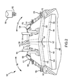
- FIG. 2 is a schematic, perspective view of one embodiment of a system for producing friction-stir weldments.
- FIG. 3 is a schematic, cross-sectional view of another embodiment of a system for producing friction-stir weldments.
- FIG. 4 is a schematic, cross-sectional view of another embodiment of a system for producing friction-stir weldments.
- FIG. 5 is a schematic, cross-sectional view of another embodiment of a system for producing friction-stir weldments.
- FIG. 6 is a schematic, perspective view of another embodiment of a system for producing friction-stir weldments.
- FIG. 7 is a schematic, cross-sectional view of another embodiment of a system for producing friction-stir weldments.
- FIG. 8 is a flow chart illustrating embodiments of methods for producing friction-stir weldments.
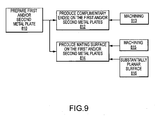
- FIG. 9 is a flow chart illustrating an embodiment of a method for preparing metal plates.
- FIG. 10 is a schematic view illustrating various prepared metal plates.
- FIG. 11a is a photograph illustrating a top-face side of a friction-stir weldment.
- FIG. 11b is a photograph illustrating a bottom-root side of a friction-stir weldment.
- “Friction-stir welding” means a solid-state joining process for joining two or more metal products to one another. The joining is effected by forcing a rotating friction-stir welding tool into the joining area to plasticize the metal proximal the tool. The plasticized regions coalesce into sound metallurgical bonds.
- Plasticize means to soften metal without substantially liquefying and/or melting the metal.
- “Friction-stir welding tool” means any apparatus capable of friction-stir welding, such as conventional single-probe tools, or bobbin-style tools.
- “Friction-stir corner weld” means a friction-stir weld that joins a first metal product to a second metal product via a friction stir welding tool, wherein, after welding, a center-neutral axis of the first metal product is transverse to a center-neutral axis of the second metal product.
- the friction-stir corner weld may include a top-face side.
- the friction-stir corner weld may include a bottom-root side.
- the friction-stir corner weld has an angle of from about 5° to about 85° or from about 95° to about 175°, as determined via the intersection of the center-neutral axis of the first and second metal products.
- Transverse means non-perpendicular with respect to an angle formed by the intersection of two planes, and includes all angles from about 5° to about 85° and from about 95° to about 175°.
- Center-neutral axis means an axis that extends through a center portion of a material (e.g., a plate).
- a “metal plate” means a metal product having a thickness of at least about 0.5 inch.
- FSW friction-stir welding
- Friction stir weldment or “FSWeldment” means a product produced from friction-stir welding.
- the FSWeldment may include a first metal plate joined to a second metal plate via a friction-stir corner weld.
- Aluminum alloy means an aluminum metal including at least one other metal alloyed therewith.
- Aluminum alloys include, but are not limited to, the 1XXX - 8XXX series aluminum alloys as defined by the Aluminum Association, Inc.
- Backup anvil means a block that at least partially counteracts the forging force (Fz) imparted by the FSW tool, and which has surfaces adapted to produce friction-stir corner welds.
- Restraining member means any various types of apparatus or systems (e.g., clamps) available to restrain pieces (e.g., metal plates) during friction stir welding.
- the restraining members should locate and firmly hold the pieces being friction-stir welded so that the pieces do not move and/or separate at the abutment of the pieces being friction-stir welded.
- Abutment means the point of contact between two objects.
- Z-force or "plunging force” or “Fz” means the force applied by a friction-stir welding tool to the pieces being friction stir welded and the plasticized material in the welding area about the FSW tool, in the generally vertical direction.
- Speed of travel means a speed of advancement of the friction-stir welding tool during friction-stir welding.
- X-force or "advancing force” or “Fx” means the force necessary to move the friction stir welding tool through the pieces during friction stir welding at a speed of travel.
- Joint efficiency means the ratio of the ultimate tensile strength of a welded joint relative to the ultimate tensile strength of the original piece.
- “Ultimate tensile strength” means the maximum stress that a material can withstand, and may be measured, for example, via ASTM E8M-04, April 2004.
- FIGS. 1a - 1b One embodiment of FSWeldment produced via a friction-stir welding tool is illustrated in FIGS. 1a - 1b .
- the FSWeldment 100 includes a first metal plate 110 and a second metal plate 120.
- a friction-stir corner weld 130 connects the first metal plate 110 to the second metal plate 120.
- the friction-stir corner weld 130 is produced via a friction-stir welding tool.
- a center-neutral axis 115 of the first metal plate 110 is transverse to a center-neutral axis 125 of the second metal plate 120.
- the FSWeldment has a friction-stir corner weld that is non-linear and non-perpendicular.
- a FSW tool and backup anvil are used to join abutting sides (sometimes referred to herein as complementary ends) of the first and second metal plates 110, 120.
- the friction-stir corner weld 130 is produced via a friction-stir welding tool, as described in further detail below.
- the friction-stir corner weld 130 generally includes a top-face side 132, and may include a bottom-root side 134, such as when full-penetration frictions-stir welds are completed.
- the friction-stir corner weld 130 includes such a top-face side 132 and a bottom-root side 134.
- the first metal plate 110 and the second metal plate 120 are connected to one another in a non-perpendicular and non-linear fashion to form the friction-stir corner weld 130, as illustrated by angle 136.
- Angle 136 may be any angle between 1° and 89° or between 179° and 91°. In one embodiment, angle 136 is from about 95° to about 175°. In another embodiment, angle 136 is from about 5° to about 85°. In the illustrated embodiment, the angle 136 is approximately 166°.
- the first metal plate 110 and the second metal plate 120 may be any metal plates adapted to be welded to one another via friction-stir welding.
- the first metal plate 110 and the second metal plate 120 comprise the same metal.
- the first metal plate 110 and the second metal plate 120 comprise differing metals.
- at least one of the metal plates comprises an aluminum alloy (e.g., any of the 2XXX, 3XXX, 5XXX, 6XXX, or 7XXX series aluminum alloys defined by the Aluminum Association, Inc).
- the first metal plate 110 comprises one of a series 5XXX and 6XXX aluminum alloy
- the second aluminum metal plate 120 comprises one of a 5XXX series and a 6XXX series aluminum alloy.
- the FSWeldments 100 may be utilized in a variety of applications.
- the FSWeldments 100 may be utilized in defense applications (e.g., armored vehicles), marine applications (e.g., hulls for ships), and energy applications (e.g., holding tanks), to name a few.
- the FS Weldments 100 generally have a joint efficiency of at least about 55%, which is dependent on the alloy combinations and their tempers before and after welding. In one embodiment, the FSWeldments 100 generally have a joint efficiency in the range of from about 55% to about 90%.
- the system 150 includes a backup anvil 160, a first set of restraining members 170, which includes two side restraining members 175 and two top restraining members 174, and a second set of restraining members 180, which includes two side restraining members 185 and two top restraining members 184.
- the system also includes a friction-stir welding tool 190 (not to scale).
- the side restraining members 175, 185 are adapted to restrain at least a portion of the distal sides 112, 122, of the first metal plate 110 and the second metal plate 120, respectively.
- the top restraining members 174, 184 are adapted to restrain top portions 114, 124 of the first and second metal plates 110, 120, respectively.
- the side restraining members 175, 185 and top restraining members 174, 184 should be designed to locate and firmly hold the metal plates 110, 120 from separating at the abutment of the proximal sides 113, 123 of the first and second metal plates 110, 120, and from uncontrollably shifting in any direction during friction-stir welding.
- the side restraining members 175, 185 each may be interconnected to a selectively positionable member 176, 186 (e.g., a screw) so that it is capable of selectively positioning the side restraining members 175, 185 relative to the distal sides 112, 122.
- the selectively positionable members 176, 186 may thus be selectively advanced and retracted to facilitate engagement with the metal plates 110, 120, such as via movement (e.g., rotation) of heads 177, 187 (illustrated in FIG. 3 ).
- restraining members per metal plate are used. In practice, at least one, but preferably a plurality of restraining members per metal plate may be used.
- the type and number of restraining members is a function of, for instance, the geometry and dimensions (e.g., the length, width and/or thickness) of the metal plates being friction-stir welded.
- the first and second sets of restraining members 170, 180 include two top clamps 174, 184 and two side clamps 175, 185. However, other suitable restraining members may be utilized.
- the backup anvil 160 includes a first face 162 and a second face 164.
- the first face 162 is opposite the second face 164 and has a top axis 163 that is transverse to a top axis 165 of the second face 164.
- the first face 162 is adapted to support the first metal plate 110 during friction-stir welding
- the second face 164 is adapted to support the second metal plate 120 during friction-stir welding.
- the backup anvil 160 may include a pointed tip 167 as defined by the intersection of the top axis 163, 165 of the first and second faces 162, 164.
- the backup anvil 160 may include a flat top portion.
- the backup anvil should comprise a material that is sufficiently sturdy to counteract the forging force (Fz) imparted by the FSW tool, such as a metal (e.g., steel, iron) a ceramic, or any other suitably sturdy material.
- the metal plates 110, 120 may be prepared so as to facilitate production of the friction-stir corner weld, such as by machining one or more surfaces of at least one of the metal plates 110, 120 (e.g. to produce machined surfaces 116, 126). After preparation (if necessary), the first and second metal plates may be placed on the backup anvil 160. In the illustrated embodiment, the first metal plate 110 is oriented such that its center-neutral axis 115 is coincidental to (e.g., parallel to or slightly offset from) the top axis 163 of the first side 162 of the anvil 160.
- the center-neutral axis 125 of the second metal plate 120 is coincidental to the top axis 165 of the second side 164 of the anvil 160.
- the center-neutral axis 115 of the first metal plate 110 is transverse to the center-neutral axis 125 of the second metal plate 120.
- the proximal side portions 113, 123 of the first metal plate 110 and second metal plate 120, respectively, are proximal one another (e.g., abutting) so as to facilitate production of the friction-stir corner weld 130 (not indicated on FIG. 2 ) via friction-stir welding tool 190.
- FSWeldments having friction-stir corner welds may be produced.
- the first set of restraining members 170 are positioned to restrain one plate 120, and the second set of restraining members 180 are positioned to restrain another metal plate 110.
- a pin 192 of a friction-stir welding tool 190 is plunged between proximal sides 113, 123 of the first and second metal plates 110, 120, respectively, to produce the friction-stir corner weld 130 and thus to produce the FSWeldment.
- the friction-stir welding parameters may be varied based on application.
- a conventional friction-stir welding process utilizes a Z-force of not greater than about 13,000 lbf and produces an X-force of not greater than about 2,000 lbf.
- the friction-stir welding tool may spin at an RPM of not greater than about 250 RPM and may have a travel speed of not greater than about 6 inches per minute.
- the process may utilize a Z-force, which is the force imparted to the parts and plasticized material in the FSW area, between the two shoulders of the FSW tool, of not greater than about 1,000 lbf and produce an X-force of not greater than about 1,300 lbf.
- the spin may be not greater than about 225 RPM, and the travel speed may be not greater than about 4 inches per minute.
- the backup anvil 160 may include a pointed tip 167 to facilitate production of friction-stir corner welds 130 having a likewise pointed bottom welded surface (e.g., the top axis of the first and second metal faces 162, 164 intersect at the point near or at the interface of the proximal sides 113, 123).
- the backup anvil may have a flat top portion, which may facilitate production of friction-stir corner welds having a planar bottom welded surface.
- a system 155 may include a backup anvil 160' having first and second faces 162', 164', where the top axis (not illustrated) of the first and second faces 162', 164' do not intersect at the interface between the proximal sides 113, 123 of the first and second metal plates 110, 120.
- a flat top portion 168 may be included with the backup anvil 160'.
- the flat top portion 168 may be flush with bottom surfaces of at least one of the first and second metal plates 110, 120 so as to support such bottom surfaces during friction-stir welding.
- FSWeldments having a planar friction-stir corner welded surface (e.g., an interior or exterior surface) may be produced.
- a backup anvil 160'' may be used to support top portions of the metal plates 110, 120 and empty space 199 may be included below the metal plates 110, 120 to facilitate movement of a friction-stir welding tool 190 therethrough.
- the anvil is flush with the metal plates 110, 120 and stabilizes / restrains the plates 110, 120.
- a metal plate 169 may be used to facilitate engagement of the anvil and the metal plates 110, 120 proximal the weld zone. In this embodiment, top clamps may not be required.
- a conventional restraining apparatus 197 e.g., alternating vacuum channels and gaskets
- the friction-stir welding tool 190 may also include appropriate shoulders 193 to facilitate interface with the metal plates 110, 120 during the production of the friction-stir corner weld.
- a backup anvil 160''' may be arranged to support both the metal plates 110, 120, without the use of internal restraining features.
- the anvil itself, acts to support the plates by mirroring the shape of the weldment.
- First and second clamps 178, 188 may be utilized to restrain the first and second metal plates 110, 120, respectively, from a direction opposite to that provided by the anvil 160'''.
- the friction-stir welding tool 190 may include appropriate shoulders 193 to facilitate interface with the metal plates 110, 120 and production of the friction-stir corner weld.
- the pin 192 of the friction-stir welding tool 190 is more elongated than those illustrated in FIG. 2 , 3 , and 4 .
- Such a pin 192 may be used, for example, when a deeper weld is required.
- a system 250 may include a backup anvil 260 having a first portion 262 and a second portion 264.
- the first portion 262 includes a first face 266 for at least partially supporting a first metal plate 110 to be friction-stir welded via a bobbin-style friction-stir welding tool 290 (not to scale).
- the first portion 262 further includes a top axis 263.
- the second portion 264 includes a second face 267 for at least partially supporting the second metal plate 120.
- the second portion 264 further includes a top axis 265.
- the intersection of the top axis 263, 265 is non-linear and non-perpendicular, thus facilitating production of friction-stir corner welds.
- the first and second portions 262, 264 may be fixedly restrained such that they are unable to move during friction-stir welding.
- the first and second portions 262, 264 may be bolted to an underlying frame and/or restraints may exist in the space 299 such that the first and second portions 262, 264 are unable to move away from each other during welding.
- the backup anvil 260 further includes an open space 299 to accommodate movement of the bobbin tool 290 therethrough.
- First and second sets of restraining members 170, 180 may be utilized to restrain the metal plates 110, 120 during friction-stir welding.
- the system 250 operates similar to system 150, described above with reference to FIG. 2 , except that, during operation, the bobbin-style friction-stir welding tool 290 will be moved into and translated through the joint formed by the abutting complementary ends 113, 123 of the first metal plate 110 and the second metal plate 120.
- the center-plane of the friction-stir corner weld may be substantially parallel to a center line of the welding pin of the bobbin tool 290, but the center-neutral axis 115, 125 of the first and second metal plates 110, 120 will be transverse to one another due to the configuration of the backup anvil 260.
- FS Weldments having friction-stir corner welds may be produced via bobbin-style friction-stir welding tools.
- the backup anvil may be split into two separate pieces.
- the backup anvil 260' may be a unitary material and open space 299' may be included therein, as illustrated in FIG. 7 .
- the method includes the steps of restraining first and/or second metal plates to a backup anvil (820) and welding the first metal plate to the second metal plate via a friction-stir welding apparatus (830).
- the method may also optionally include the step of preparing the first and/or second metal plates (810) for the restraining step (820) and/or the welding step (830).
- the metal plates may be prepared by producing one or more complementary ends on the first and/or second metal plates (812).
- the ends are machined (813) via conventional machining apparatus / processes.
- the first and/or second metal plates may also be prepared by producing one or more mating surfaces on the first and/or second metal plates (814).
- the mating surfaces are produced via machining (813), such as via a conventional machining apparatus / processes.
- the mating surface may be a substantially planar surface (816), which may facilitate engagement with a pin of a friction-stir welding tool.
- the complementary ends are produced before the mating surfaces are produced. However, the mating surfaces may be produced before the complementary ends are produced, or the complementary ends and the mating surfaces may be produced concomitantly.
- FIG. 10 An example of a method for producing complementary ends and mating surfaces to facilitate production of FSWeldments is illustrated in FIG. 10 .
- a first end 1005 of a base metal plate 1000 may be machined to produce a complementary end 1015 of metal plate 1010.
- This complementary end 1015 may be machined to any suitable taper to facilitate production of the friction-stir weldment having the appropriate friction-stir corner weld angle.
- the mating surface may facilitate engagement between surfaces of the plates and the friction-stir welding tool.
- a complementary end 1015 and/or top portion 1017 of tapered metal plate 1010 may be machined to produce a mating surface 1025 of metal plate 1020.
- metal plate 1020 having a complementary end 1015 and a mating surface 1025
- another metal plate 2020 also having a complementary end 2015 and a mating surface 2025
- the complementary ends 1015, 2015 may abut one another in a substantially planar fashion
- mating surfaces 1025, 2025 may form a substantially planar surface (e.g., a planar top and/or bottom surface).
- the substantially planar surface may facilitate engagement with a pin of a friction-stir welding tool.
- mating surfaces may be produced on both the top and bottom sides of the metal plates.
- Other surfaces of a plate or plates may also be machined to facilitate production of the FSWeldments.
- interfacing top, bottom, or side surfaces of a plate or plates may be machined to facilitate engagement with the backup anvil and/or restraining members.
- a distal side of a plate is machined to facilitate engagement between an side restraining member and the distal side of the metal plate (e.g., as illustrated in FIG. 3 ).
- the first metal plate may be restrained to a first side of the anvil and the second metal plate may be restrained to a second side of the anvil in any suitable manner, such as those described above.
- at least one restraining member is utilized to restrain the first and/or second metal plates to the anvil.
- the restraining step (820) generally results in the center axis of the first metal plate being transverse to the center axis of the second metal plate (822).
- the welding step is completed (830), described below, the metal plates may be transverse to one another in the friction stir weldment.
- the welding step (830) may be completed by any conventional friction-stir welding apparatus.
- a conventional friction-stir welding apparatus may be plunged between abutting ends of the first metal plate and the second metal plate to plasticize such ends and produce a friction-stir corner weld.
- the first plate is a 0.84 inch thick 6013-T6 series aluminum alloy and the second plate is a 0.84 inch thick 6013-T6 series aluminum alloy.
- the abutting ends of the plates have a 0.75 inch thickness at the abutment.
- a friction-stir welding tool is used to weld the first plate to the second plate.
- the backup anvil has an included angle of 165° as measured at the abutment of the plates.
- Operating parameters include 5 inches per minute speed of travel, 224 RPM tool rotation rate, 2° forward FSW tool angle, and about 11,100 lbf forging force (Fz) with a resultant 2,100 lbf reaction force (Fx) on the advancing FSW tool, thereby producing a FSWeldment having a friction-stir corner weld.
- the friction-stir corner weld has a top-face side and a bottom-root side, as illustrated in FIGS 11a and 11b .
- the FSWeldment has an interior angle of about 166°.
- the first plate is a 0.84 inch thick 5083-O plate and the second plate is a 0.84 inch thick 5083-O plate.
- the abutting ends of the plates have a 0.75 inch thickness at the abutment.
- a friction-stir welding tool is used to weld the first plate to the second plate.
- the backup anvil has an included angle of 165° as measured at the abutment of the plates.
- Operating parameters include 3.5 inches per minute speed of travel, 140 rpm tool rotation rate, 2° forward FSW tool angle, and about 13,100 lbf forging force (Fz) with a resultant 2,200 lbf reaction force on the advancing FSW tool, thereby producing a FSWeldment having a friction-stir corner weld.
- the first plate is a 0.84 inch thick 5083-0 plate and the second plate is a 0.84 inch thick 6013-T6 plate.
- the abutting ends of the plates have a 0.75 inch thickness at the abutment.
- a friction-stir welding tool is used to weld the first plate to the second plate.
- the backup anvil has an include angle of 165° as measured at the abutment of the plates.
- Operating parameters include 3.5 inches per minute speed of travel, 140 rpm tool rotation rate, 2° forward FSW tool angle, and about 12,500 lbf forging force (Fz) between the shoulders of the FSW tool with a resultant 2,000 lbf reaction force (Fx) on the advancing FSW tool, thereby producing a FSWeldment having a friction-stir corner weld.
- Example 2 Production of friction-stir corner welds using a bobbin-style friction-stir welding tool
- the first plate is a 0.84 inch thick 6013-T6 plate and the second plate is a 0.84 inch thick 6013-T6 plate.
- the abutting ends of the plates have a 0.75 inch thickness at the abutment.
- a bobbin-style friction-stir welding tool is used to weld the first plate to the second plate.
- the backup anvil has an include angle of 165° as measured at the abutment of the plates.
- Operating parameters include 3.5 inches per minute speed of travel, 224 rpm tool rotation rate, about 1,000 lbf forging force (Fz) with a resultant 1,300 lbf reaction force on the advancing FSW tool, thereby producing a FSWeldment having a friction-stir corner weld.
Landscapes
- Engineering & Computer Science (AREA)
- Mechanical Engineering (AREA)
- Pressure Welding/Diffusion-Bonding (AREA)
Abstract
Description
- Friction-stir welding is a welding method that joins two or more metal pieces, generally without melting, and is primarily applicable to welding jobs where the metals' characteristics must see minimal change due to welding heat. The process may involve a rotating tool being pressed into the two or more metal pieces at the location of a desired weld. Heat from friction and deformation may plasticize the metal near the rotating tool. The plasticized regions coalesce into sound metallurgical bonds.
- Broadly, the instant application relates to friction-stir weldments having friction-stir corner welds that are non-linear and non-perpendicular, and systems and methods for producing the same. The friction-stir weldment may find application in a variety of industrial applications due to the presence of the non-linear and non-perpendicular friction-stir corner weld.
- In one aspect, metal products comprising friction-stir weldments are provided. In one approach, the products include a first metal plate having a first center-neutral axis, a second metal plate having a second center-neutral axis and a friction-stir corner weld that connects the first metal plate to the second metal plate, where the first center-neutral axis of the first metal plate is transverse to the second center-neutral axis of the second metal plate. Thus, the metal products may be considered corner welded. In one embodiment, the intersection between the first center-neutral axis and the second center-neutral axis defines an angle of from about 5° to about 85° or from about 95° to about 175°. In one embodiment, the corner weld comprises a top-face side and a bottom-root side, and where an angle of the corner weld proximal the bottom-root side is from about 5° to about 85° or from about 95° to about 175°.
- The metal plates may be any suitable material capable of being welded via a friction-stir welding tool. In one embodiment, a first metal plate comprises a first aluminum alloy and a second metal plate comprises a second aluminum alloy. In one embodiment, the first aluminum alloy is different than the second aluminum alloy (e.g., a different composition or temper, to name two). In one embodiment, the first aluminum alloy is the same as the second aluminum alloy.
- In another aspect, systems for producing friction-stir weldments are provided. In one approach, the system includes a backup anvil having a first supporting face and a second supporting face, a first set of restraining members capable of restrictively restraining the first metal plate on the first supporting face of the backup anvil, a second set of restraining members capable of restrictively restraining the second metal plate on the second supporting face of the backup anvil, and a friction-stir welding tool capable of welding the first metal plate to the second metal plate to produce a friction-stir weldment having a corner weld. In this approach, the second supporting face is generally opposite of the first supporting face. The first supporting face is generally adapted to receive and support a first metal plate, and the second supporting face is generally adapted to receive and support a second metal plate. The faces are generally oriented such that, after welding, the center-neutral axis of the first metal plate will be transverse to the center-neutral axis of the second metal plate.
- The restraining members may be configured in any suitable orientation to restrict movement of the metal plates during welding. In one embodiment, either the first or second set of restraining members is capable of restrictively restraining a side portion of a metal plate. In a related embodiment, the other of the first and second set of restraining members is capable of restraining a top portion of the metal plate.
- The backup anvil is generally configured to support the metal plates during welding such that, after welding, the center-neutral axis of a first metal plate is transverse to a center neutral axis of a second metal plate. In one embodiment, the backup anvil includes a pointed tip. In one embodiment, the backup anvil includes a flat top portion.
- In one embodiment, the system includes an open space between the first supporting face and the second supporting face. In one embodiment, the friction-stir welding tool is a bobbin-style tool, and the open space is adapted to allow passage of a portion of the bobbin-style tool therethrough during friction-stir welding.
- In yet another aspect, methods for producing friction-stir weldments are provided. In one embodiment, a method includes the steps of first restraining a first metal plate to a backup anvil in a first orientation, where the first metal plate comprises a first complementary end and a center-neutral axis, second restraining a second metal plate to the backup anvil in a second orientation, where the second metal plate comprises a second complementary end and a center-neutral axis, where, after the second restraining step, the first complementary end of the first metal plate abuts the second complementary end of the second metal plate and the center-neutral axis of the first metal plate is transverse to the center-neutral axis of the second metal plate, and welding the first metal plate to the second metal plate at the first and second complementary ends via a friction-stir welding tool, thereby producing a friction-stir weldment where the center-neutral axis of the first metal plate is transverse to the second center-neutral axis of the metal plate.
- The plates may be prepared prior to restraining and/or welding. In one embodiment, a method includes, prior to a restraining step, preparing the metal plate. The preparing step may include machining an end of the metal plate to produce a complementary end. After the machining step, the complementary end may be capable of abutting another complementary end such that the center-neutral axis of the plates comprising the complementary ends are transverse to one another. In one embodiment, a method includes machining an end of another metal plate to produce the other complementary end. In one embodiment, the machining of the metal plate step includes machining a top portion of the metal plate to produce a mating surface, where the mating surface is adapted for engagement with a friction-stir welding tool. In one embodiment, a mating surface is a first mating surface, and a method further includes machining a top portion of another metal plate to produce a another mating surface, where this other mating surface is adapted for engagement with a friction-stir welding tool. In one embodiment, after metal plates are restrained, these mating surfaces of the define a substantially planar surface, and the substantially planar surface is adapted for engagement with a friction-stir welding tool.
According to the present invention, there is provided a metal product comprising a first metal plate comprising a first center-neutral axis; a second metal plate comprising a second center-neutral axis; and a friction-stir corner weld that connects the first metal plate to the second metal plate, wherein the first center-neutral axis of the first metal plate is transverse to the second center-neutral axis of the second metal plate.
Preferably, the intersection between the first center-neutral axis and the second center-neutral axis defines an angle of from about 5° to about 85° or from about 95° to about 175°.
Advantageously, the corner weld comprises a top-face side and a bottom-root side, and wherein an angle of the corner weld proximal the bottom-root side is from about 5° to about 85° or from about 95° to about 175°.
Conveniently, the first metal plate comprises a first aluminum alloy and the second metal plate comprises a second aluminum alloy.
Preferably, the first aluminum alloy is different than the second aluminum alloy.
The present invention also provides a system comprising a backup anvil having a first supporting face and a second supporting face, wherein the second supporting face is opposite of the first supporting face, wherein the first supporting face is adapted to receive and support a first metal plate, and wherein the second supporting face is adapted to receive and support a second metal plate, wherein the center-neutral axis of the first metal plate is transverse to the center-neutral axis of the second metal plate; a first set of restraining members capable of restrictively restraining the first metal plate on the first supporting face of the backup anvil; a second set of restraining members capable of restrictively restraining the second metal plate on the second supporting face of the backup anvil; and a friction-stir welding tool capable of welding the first metal plate to the second metal plate to produce a friction-stir weldment having a friction-stir corner weld, wherein, as welded, the center-neutral axis of the first metal plate is transverse to the center-neutral axis of the second metal plate.
Preferably, the system further comprises open space the first supporting face and the second supporting face.
Conveniently, the friction-stir welding tool is a bobbin-style tool, and wherein the open space is adapted to allow passage of a portion of the bobbin-style tool therethrough during friction-stir welding.
Advantageously, one of the first set of restraining members is capable of restrictively restraining an side portion of the first metal plate.
Conveniently, one of the first set of restraining members is capable of restraining a top portion of the first metal plate.
Preferably, the backup anvil includes a pointed tip.
Advantageously, the backup anvil includes a flat top portion.
The invention also provides a method comprising first restraining a first metal plate to a backup anvil in a first orientation, wherein the first metal plate comprises a first complementary end and a center-neutral axis; second restraining a second metal plate to the backup anvil in a second orientation, wherein the second metal plate comprises a second complementary end and a center-neutral axis, wherein after the second restraining step the first complementary end of the first metal plate abuts the second complementary end of the second metal plate, and wherein the center-neutral axis of the first metal plate is transverse to the center-neutral axis of the second metal plate; and welding the first metal plate to the second metal plate at the first and second complementary ends via a friction-stir welding tool, thereby producing a friction-stir weldment having the center-neutral axis of the first metal plate transverse to the second center-neutral axis of the metal plate.
Preferably, the method further comprises, prior to the first restraining step, preparing the first metal plate, wherein the preparing comprises: machining an end of the first metal plate to produce the first complementary end, wherein after the machining step, the first complementary end is capable of abutting the second complementary end such that the center-neutral axis of the first metal plate is transverse to the center-neutral axis of the second metal plate.
Advantageously, the machining of the first metal plate step comprises machining a top portion of the first metal plate to produce a mating surface, wherein the mating surface is adapted for engagement with a friction-stir welding tool.
Advantageously, the method further comprises machining an end of the second metal plate to produce the second complementary end.
Preferably, the mating surface is a first mating surface, and wherein the method further comprises: machining a top portion of the second metal plate to produce a second mating surface, wherein the second mating surface is adapted for engagement with a friction-stir welding tool.
Advantageously, after the first restraining and second restraining steps, the first and second mating surfaces of the first and second metal plates define a substantially planar surface, wherein the substantially planar surface is adapted for engagement with a friction-stir welding tool. - As may be appreciated, various ones of the inventive aspects noted hereinabove may be combined to yield various friction-stir weldments. These and other aspects, advantages, and novel features of the invention are set forth in part in the description that follows and will become apparent to those skilled in the art upon examination of the following description and figures, or may be learned by practicing the invention.
-
FIG. 1a is a perspective view illustrating one embodiment of a friction-stir weldment having a friction-stir corner weld. -
FIG. 1b is a close-up view of the friction-stir corner weld ofFIG. 1a . -
FIG. 2 is a schematic, perspective view of one embodiment of a system for producing friction-stir weldments. -
FIG. 3 is a schematic, cross-sectional view of another embodiment of a system for producing friction-stir weldments. -
FIG. 4 is a schematic, cross-sectional view of another embodiment of a system for producing friction-stir weldments. -
FIG. 5 is a schematic, cross-sectional view of another embodiment of a system for producing friction-stir weldments. -
FIG. 6 is a schematic, perspective view of another embodiment of a system for producing friction-stir weldments. -
FIG. 7 is a schematic, cross-sectional view of another embodiment of a system for producing friction-stir weldments. -
FIG. 8 is a flow chart illustrating embodiments of methods for producing friction-stir weldments. -
FIG. 9 is a flow chart illustrating an embodiment of a method for preparing metal plates. -
FIG. 10 is a schematic view illustrating various prepared metal plates. -
FIG. 11a is a photograph illustrating a top-face side of a friction-stir weldment. -
FIG. 11b is a photograph illustrating a bottom-root side of a friction-stir weldment. - The following non-limiting definitions are used herein to assist in describing various aspects, approaches and embodiments of the instant invention.
- "Friction-stir welding" means a solid-state joining process for joining two or more metal products to one another. The joining is effected by forcing a rotating friction-stir welding tool into the joining area to plasticize the metal proximal the tool. The plasticized regions coalesce into sound metallurgical bonds.
- "Plasticize" means to soften metal without substantially liquefying and/or melting the metal.
- "Friction-stir welding tool" means any apparatus capable of friction-stir welding, such as conventional single-probe tools, or bobbin-style tools.
- "Friction-stir corner weld" means a friction-stir weld that joins a first metal product to a second metal product via a friction stir welding tool, wherein, after welding, a center-neutral axis of the first metal product is transverse to a center-neutral axis of the second metal product. The friction-stir corner weld may include a top-face side. For full penetration welds, the friction-stir corner weld may include a bottom-root side. In one embodiment, the friction-stir corner weld has an angle of from about 5° to about 85° or from about 95° to about 175°, as determined via the intersection of the center-neutral axis of the first and second metal products.
- "Transverse" means non-perpendicular with respect to an angle formed by the intersection of two planes, and includes all angles from about 5° to about 85° and from about 95° to about 175°.
- "Center-neutral axis" means an axis that extends through a center portion of a material (e.g., a plate).
- A "metal plate" means a metal product having a thickness of at least about 0.5 inch.
- "FSW" means friction-stir welding.
- "Friction stir weldment" or "FSWeldment" means a product produced from friction-stir welding. The FSWeldment may include a first metal plate joined to a second metal plate via a friction-stir corner weld.
- "Aluminum alloy" means an aluminum metal including at least one other metal alloyed therewith. Aluminum alloys include, but are not limited to, the 1XXX - 8XXX series aluminum alloys as defined by the Aluminum Association, Inc.
- "Backup anvil" means a block that at least partially counteracts the forging force (Fz) imparted by the FSW tool, and which has surfaces adapted to produce friction-stir corner welds.
- "Restraining member" means any various types of apparatus or systems (e.g., clamps) available to restrain pieces (e.g., metal plates) during friction stir welding. The restraining members should locate and firmly hold the pieces being friction-stir welded so that the pieces do not move and/or separate at the abutment of the pieces being friction-stir welded.
- "Abutment" means the point of contact between two objects.
- "Z-force" or "plunging force" or "Fz" means the force applied by a friction-stir welding tool to the pieces being friction stir welded and the plasticized material in the welding area about the FSW tool, in the generally vertical direction.
- "Speed of travel" means a speed of advancement of the friction-stir welding tool during friction-stir welding.
- "X-force" or "advancing force" or "Fx" means the force necessary to move the friction stir welding tool through the pieces during friction stir welding at a speed of travel.
- "Joint efficiency" means the ratio of the ultimate tensile strength of a welded joint relative to the ultimate tensile strength of the original piece.
- "Ultimate tensile strength" means the maximum stress that a material can withstand, and may be measured, for example, via ASTM E8M-04, April 2004.
- Reference will now be made in detail to the accompanying drawings, which at least assist in illustrating various pertinent embodiments of the present invention. One embodiment of FSWeldment produced via a friction-stir welding tool is illustrated in
FIGS. 1a - 1b . In the illustrated embodiment, theFSWeldment 100 includes afirst metal plate 110 and asecond metal plate 120. A friction-stir corner weld 130 connects thefirst metal plate 110 to thesecond metal plate 120. The friction-stir corner weld 130 is produced via a friction-stir welding tool. In the illustrated embodiment, a center-neutral axis 115 of thefirst metal plate 110 is transverse to a center-neutral axis 125 of thesecond metal plate 120. Thus, the FSWeldment has a friction-stir corner weld that is non-linear and non-perpendicular. To produce the FSWeldment, and as described in further detail below, a FSW tool and backup anvil are used to join abutting sides (sometimes referred to herein as complementary ends) of the first andsecond metal plates - The friction-
stir corner weld 130 is produced via a friction-stir welding tool, as described in further detail below. In this regard, the friction-stir corner weld 130 generally includes a top-face side 132, and may include a bottom-root side 134, such as when full-penetration frictions-stir welds are completed. In the illustrated embodiment ofFIG. 1b , the friction-stir corner weld 130 includes such a top-face side 132 and a bottom-root side 134. Thefirst metal plate 110 and thesecond metal plate 120 are connected to one another in a non-perpendicular and non-linear fashion to form the friction-stir corner weld 130, as illustrated byangle 136.Angle 136 may be any angle between 1° and 89° or between 179° and 91°. In one embodiment,angle 136 is from about 95° to about 175°. In another embodiment,angle 136 is from about 5° to about 85°. In the illustrated embodiment, theangle 136 is approximately 166°. - The
first metal plate 110 and thesecond metal plate 120 may be any metal plates adapted to be welded to one another via friction-stir welding. In one embodiment, thefirst metal plate 110 and thesecond metal plate 120 comprise the same metal. In another embodiment, thefirst metal plate 110 and thesecond metal plate 120 comprise differing metals. In one embodiment, at least one of the metal plates comprises an aluminum alloy (e.g., any of the 2XXX, 3XXX, 5XXX, 6XXX, or 7XXX series aluminum alloys defined by the Aluminum Association, Inc). In one embodiment, thefirst metal plate 110 comprises one of a series 5XXX and 6XXX aluminum alloy, and the secondaluminum metal plate 120 comprises one of a 5XXX series and a 6XXX series aluminum alloy. - The
FSWeldments 100 may be utilized in a variety of applications. For example, theFSWeldments 100 may be utilized in defense applications (e.g., armored vehicles), marine applications (e.g., hulls for ships), and energy applications (e.g., holding tanks), to name a few. TheFS Weldments 100 generally have a joint efficiency of at least about 55%, which is dependent on the alloy combinations and their tempers before and after welding. In one embodiment, theFSWeldments 100 generally have a joint efficiency in the range of from about 55% to about 90%. - Systems for producing
FSWeldments 100 are also provided, one embodiment of which is illustrated inFIG. 2 . In the illustrated embodiment, thesystem 150 includes abackup anvil 160, a first set of restrainingmembers 170, which includes twoside restraining members 175 and twotop restraining members 174, and a second set of restrainingmembers 180, which includes twoside restraining members 185 and twotop restraining members 184. The system also includes a friction-stir welding tool 190 (not to scale). - The
side restraining members distal sides first metal plate 110 and thesecond metal plate 120, respectively. Thetop restraining members top portions second metal plates side restraining members top restraining members metal plates proximal sides second metal plates side restraining members positionable member 176, 186 (e.g., a screw) so that it is capable of selectively positioning theside restraining members distal sides positionable members metal plates heads 177, 187 (illustrated inFIG. 3 ). - As illustrated, four restraining members per metal plate are used. In practice, at least one, but preferably a plurality of restraining members per metal plate may be used. The type and number of restraining members is a function of, for instance, the geometry and dimensions (e.g., the length, width and/or thickness) of the metal plates being friction-stir welded. As illustrated, the first and second sets of restraining
members top clamps - The
backup anvil 160 includes afirst face 162 and asecond face 164. Thefirst face 162 is opposite thesecond face 164 and has atop axis 163 that is transverse to atop axis 165 of thesecond face 164. Thefirst face 162 is adapted to support thefirst metal plate 110 during friction-stir welding, and thesecond face 164 is adapted to support thesecond metal plate 120 during friction-stir welding. Thebackup anvil 160 may include apointed tip 167 as defined by the intersection of thetop axis second faces backup anvil 160 may include a flat top portion. The backup anvil should comprise a material that is sufficiently sturdy to counteract the forging force (Fz) imparted by the FSW tool, such as a metal (e.g., steel, iron) a ceramic, or any other suitably sturdy material. - Prior to being welded, and as described in further detail below, the
metal plates metal plates 110, 120 (e.g. to produce machinedsurfaces 116, 126). After preparation (if necessary), the first and second metal plates may be placed on thebackup anvil 160. In the illustrated embodiment, thefirst metal plate 110 is oriented such that its center-neutral axis 115 is coincidental to (e.g., parallel to or slightly offset from) thetop axis 163 of thefirst side 162 of theanvil 160. The center-neutral axis 125 of thesecond metal plate 120 is coincidental to thetop axis 165 of thesecond side 164 of theanvil 160. Thus, as positioned for friction-stir welding, the center-neutral axis 115 of thefirst metal plate 110 is transverse to the center-neutral axis 125 of thesecond metal plate 120. Theproximal side portions first metal plate 110 andsecond metal plate 120, respectively, are proximal one another (e.g., abutting) so as to facilitate production of the friction-stir corner weld 130 (not indicated onFIG. 2 ) via friction-stir welding tool 190. Thus, FSWeldments having friction-stir corner welds may be produced. - In operation, the first set of restraining
members 170 are positioned to restrain oneplate 120, and the second set of restrainingmembers 180 are positioned to restrain anothermetal plate 110. Next, apin 192 of a friction-stir welding tool 190 is plunged betweenproximal sides second metal plates stir corner weld 130 and thus to produce the FSWeldment. The friction-stir welding parameters may be varied based on application. In one embodiment, a conventional friction-stir welding process utilizes a Z-force of not greater than about 13,000 lbf and produces an X-force of not greater than about 2,000 lbf. In a related embodiment, the friction-stir welding tool may spin at an RPM of not greater than about 250 RPM and may have a travel speed of not greater than about 6 inches per minute. - With respect to bobbin-style friction-stir welding tools (described below), the process may utilize a Z-force, which is the force imparted to the parts and plasticized material in the FSW area, between the two shoulders of the FSW tool, of not greater than about 1,000 lbf and produce an X-force of not greater than about 1,300 lbf. In such embodiments, the spin may be not greater than about 225 RPM, and the travel speed may be not greater than about 4 inches per minute.
- As noted above, the
backup anvil 160 may include apointed tip 167 to facilitate production of friction-stir corner welds 130 having a likewise pointed bottom welded surface (e.g., the top axis of the first and second metal faces 162, 164 intersect at the point near or at the interface of theproximal sides 113, 123). In other embodiments, the backup anvil may have a flat top portion, which may facilitate production of friction-stir corner welds having a planar bottom welded surface. For example, and with reference toFIG. 3 , asystem 155 may include a backup anvil 160' having first and second faces 162', 164', where the top axis (not illustrated) of the first and second faces 162', 164' do not intersect at the interface between theproximal sides second metal plates top portion 168 may be included with the backup anvil 160'. The flattop portion 168 may be flush with bottom surfaces of at least one of the first andsecond metal plates - Other backup anvil configurations may also be utilized. For example, and with reference to
FIG. 4 , a backup anvil 160'' may be used to support top portions of themetal plates empty space 199 may be included below themetal plates stir welding tool 190 therethrough. In the illustrated embodiment, the anvil is flush with themetal plates plates metal plate 169 may be used to facilitate engagement of the anvil and themetal plates plates stir welding tool 190 may also includeappropriate shoulders 193 to facilitate interface with themetal plates - In another embodiment, and with reference to
FIG. 5 , a backup anvil 160''' may be arranged to support both themetal plates second clamps second metal plates FIG. 4 , the friction-stir welding tool 190 may includeappropriate shoulders 193 to facilitate interface with themetal plates pin 192 of the friction-stir welding tool 190 is more elongated than those illustrated inFIG. 2 ,3 , and4 . Such apin 192 may be used, for example, when a deeper weld is required. - In the above embodiments, conventional friction-stir welding tools were utilized to illustrate production of friction-stir corner welds. In other embodiments, bobbin-style friction stir welding tools may be employed to produce friction-stir corner welds. For example, and with reference to
FIG. 6 , asystem 250 may include abackup anvil 260 having afirst portion 262 and asecond portion 264. Thefirst portion 262 includes afirst face 266 for at least partially supporting afirst metal plate 110 to be friction-stir welded via a bobbin-style friction-stir welding tool 290 (not to scale). Thefirst portion 262 further includes atop axis 263. Thesecond portion 264 includes asecond face 267 for at least partially supporting thesecond metal plate 120. Thesecond portion 264 further includes atop axis 265. The intersection of thetop axis second portions second portions space 299 such that the first andsecond portions backup anvil 260 further includes anopen space 299 to accommodate movement of thebobbin tool 290 therethrough. First and second sets of restrainingmembers metal plates - The
system 250 operates similar tosystem 150, described above with reference toFIG. 2 , except that, during operation, the bobbin-style friction-stir welding tool 290 will be moved into and translated through the joint formed by the abutting complementary ends 113, 123 of thefirst metal plate 110 and thesecond metal plate 120. With respect to the bobbin-style system 250, the center-plane of the friction-stir corner weld may be substantially parallel to a center line of the welding pin of thebobbin tool 290, but the center-neutral axis second metal plates backup anvil 260. Thus, FS Weldments having friction-stir corner welds may be produced via bobbin-style friction-stir welding tools. As illustrated inFIG. 6 , the backup anvil may be split into two separate pieces. In other embodiments, the backup anvil 260' may be a unitary material and open space 299' may be included therein, as illustrated inFIG. 7 . - Methods of producing welded metal plates are also provided, one embodiment of which is illustrated in
FIG. 8 . In the illustrated embodiment, the method includes the steps of restraining first and/or second metal plates to a backup anvil (820) and welding the first metal plate to the second metal plate via a friction-stir welding apparatus (830). The method may also optionally include the step of preparing the first and/or second metal plates (810) for the restraining step (820) and/or the welding step (830). - With respect to the preparing the first and/or second metal plates step (810), and with reference now to
FIG. 9 , the metal plates may be prepared by producing one or more complementary ends on the first and/or second metal plates (812). In one approach, the ends are machined (813) via conventional machining apparatus / processes. The first and/or second metal plates may also be prepared by producing one or more mating surfaces on the first and/or second metal plates (814). In one approach, the mating surfaces are produced via machining (813), such as via a conventional machining apparatus / processes. In one embodiment, the mating surface may be a substantially planar surface (816), which may facilitate engagement with a pin of a friction-stir welding tool. As illustrated, the complementary ends are produced before the mating surfaces are produced. However, the mating surfaces may be produced before the complementary ends are produced, or the complementary ends and the mating surfaces may be produced concomitantly. - An example of a method for producing complementary ends and mating surfaces to facilitate production of FSWeldments is illustrated in
FIG. 10 . In the illustrated embodiment, afirst end 1005 of abase metal plate 1000 may be machined to produce acomplementary end 1015 ofmetal plate 1010. Thiscomplementary end 1015 may be machined to any suitable taper to facilitate production of the friction-stir weldment having the appropriate friction-stir corner weld angle. The mating surface may facilitate engagement between surfaces of the plates and the friction-stir welding tool. In one approach, acomplementary end 1015 and/ortop portion 1017 of taperedmetal plate 1010 may be machined to produce amating surface 1025 ofmetal plate 1020. Thus, whenmetal plate 1020, having acomplementary end 1015 and amating surface 1025, is abutted with anothermetal plate 2020, also having acomplementary end 2015 and amating surface 2025, the complementary ends 1015, 2015 may abut one another in a substantially planar fashion, andmating surfaces FIG. 3 ). - Referring back to
FIG. 8 , with respect to the restraining the first and second metal plates to the anvil step (820), the first metal plate may be restrained to a first side of the anvil and the second metal plate may be restrained to a second side of the anvil in any suitable manner, such as those described above. In one embodiment, at least one restraining member is utilized to restrain the first and/or second metal plates to the anvil. The restraining step (820) generally results in the center axis of the first metal plate being transverse to the center axis of the second metal plate (822). Thus, when the welding step is completed (830), described below, the metal plates may be transverse to one another in the friction stir weldment. - The welding step (830) may be completed by any conventional friction-stir welding apparatus. In one embodiment, a conventional friction-stir welding apparatus may be plunged between abutting ends of the first metal plate and the second metal plate to plasticize such ends and produce a friction-stir corner weld.
- a) A system similar to
FIG. 2 is provided. The first plate is a 0.84 inch thick 6013-T6 series aluminum alloy and the second plate is a 0.84 inch thick 6013-T6 series aluminum alloy. The abutting ends of the plates have a 0.75 inch thickness at the abutment. A friction-stir welding tool is used to weld the first plate to the second plate. The backup anvil has an included angle of 165° as measured at the abutment of the plates. Operating parameters include 5 inches per minute speed of travel, 224 RPM tool rotation rate, 2° forward FSW tool angle, and about 11,100 lbf forging force (Fz) with a resultant 2,100 lbf reaction force (Fx) on the advancing FSW tool, thereby producing a FSWeldment having a friction-stir corner weld. The friction-stir corner weld has a top-face side and a bottom-root side, as illustrated inFIGS 11a and 11b . The FSWeldment has an interior angle of about 166°. - (b) A system similar to
FIG. 2 is provided. The first plate is a 0.84 inch thick 5083-O plate and the second plate is a 0.84 inch thick 5083-O plate. The abutting ends of the plates have a 0.75 inch thickness at the abutment. A friction-stir welding tool is used to weld the first plate to the second plate. The backup anvil has an included angle of 165° as measured at the abutment of the plates. Operating parameters include 3.5 inches per minute speed of travel, 140 rpm tool rotation rate, 2° forward FSW tool angle, and about 13,100 lbf forging force (Fz) with a resultant 2,200 lbf reaction force on the advancing FSW tool, thereby producing a FSWeldment having a friction-stir corner weld. - (c) A system similar to
FIG. 2 is provided. The first plate is a 0.84 inch thick 5083-0 plate and the second plate is a 0.84 inch thick 6013-T6 plate. The abutting ends of the plates have a 0.75 inch thickness at the abutment. A friction-stir welding tool is used to weld the first plate to the second plate. The backup anvil has an include angle of 165° as measured at the abutment of the plates. Operating parameters include 3.5 inches per minute speed of travel, 140 rpm tool rotation rate, 2° forward FSW tool angle, and about 12,500 lbf forging force (Fz) between the shoulders of the FSW tool with a resultant 2,000 lbf reaction force (Fx) on the advancing FSW tool, thereby producing a FSWeldment having a friction-stir corner weld. - (a) A system similar to
FIG. 6 is provided. The first plate is a 0.84 inch thick 6013-T6 plate and the second plate is a 0.84 inch thick 6013-T6 plate. The abutting ends of the plates have a 0.75 inch thickness at the abutment. A bobbin-style friction-stir welding tool is used to weld the first plate to the second plate. The backup anvil has an include angle of 165° as measured at the abutment of the plates. Operating parameters include 3.5 inches per minute speed of travel, 224 rpm tool rotation rate, about 1,000 lbf forging force (Fz) with a resultant 1,300 lbf reaction force on the advancing FSW tool, thereby producing a FSWeldment having a friction-stir corner weld. - While various embodiments of the present invention have been described in detail, it is apparent that modifications and adaptations of those embodiments will occur to those skilled in the art. However, it is to be expressly understood that such modifications and adaptations are within the spirit and scope of the present invention.
- In the present specification "comprises" means "includes or consists of' and "comprising" means "including or insisting of".
- The features disclosed in the foregoing description, or the following claims, or the accompanying drawings, expressed in their specific forms or in terms of a means for performing the disclosed function, or a method or process for attaining the disclosed result, as appropriate, may, separately, or in any combination of such features, be utilized for realizing the invention in diverse forms thereof.
Claims (18)
- A metal product comprising:a first metal plate comprising a first center-neutral axis;a second metal plate comprising a second center-neutral axis; anda friction-stir corner weld that connects the first metal plate to the second metal plate, wherein the first center-neutral axis of the first metal plate is transverse to the second center-neutral axis of the second metal plate.
- The metal product of Claim 1, wherein the intersection between the first center-neutral axis and the second center-neutral axis defines an angle of from about 5° to about 85° or from about 95° to about 175°.
- The metal product of Claim 1, wherein the corner weld comprises a top-face side and a bottom-root side, and wherein an angle of the corner weld proximal the bottom-root side is from about 5° to about 85° or from about 95° to about 175°.
- The metal product of Claim 1, wherein the first metal plate comprises a first aluminum alloy and the second metal plate comprises a second aluminum alloy.
- The metal product of Claim 4, wherein the first aluminum alloy is different than the second aluminum alloy.
- A system comprising:a backup anvil having a first supporting face and a second supporting face, wherein the second supporting face is opposite of the first supporting face, wherein the first supporting face is adapted to receive and support a first metal plate, and wherein the second supporting face is adapted to receive and support a second metal plate, wherein the center-neutral axis of the first metal plate is transverse to the center-neutral axis of the second metal plate;a first set of restraining members capable of restrictively restraining the first metal plate on the first supporting face of the backup anvil;a second set of restraining members capable of restrictively restraining the second metal plate on the second supporting face of the backup anvil; anda friction-stir welding tool capable of welding the first metal plate to the second metal plate to produce a friction-stir weldment having a friction-stir corner weld, wherein, as welded, the center-neutral axis of the first metal plate is transverse to the center-neutral axis of the second metal plate.
- The system of Claim 6, further comprising:open space between the first supporting face and the second supporting face.
- The system of Claim 7, wherein the friction-stir welding tool is a bobbin-style tool, and wherein the open space is adapted to allow passage of a portion of the bobbin-style tool therethrough during friction-stir welding.
- The system of Claim 6, wherein one of the first set of restraining members is capable of restrictively restraining an side portion of the first metal plate.
- The system of Claim 6, wherein one of the first set of restraining members is capable of restraining a top portion of the first metal plate.
- The system of Claim 6, wherein the backup anvil includes a pointed tip.
- The system of Claim 7, wherein the backup anvil includes a flat top portion.
- A method comprising:first restraining a first metal plate to a backup anvil in a first orientation, wherein the first metal plate comprises a first complementary end and a center-neutral axis;second restraining a second metal plate to the backup anvil in a second orientation, wherein the second metal plate comprises a second complementary end and a center-neutral axis, wherein after the second restraining step the first complementary end of the first metal plate abuts the second complementary end of the second metal plate, and wherein the center-neutral axis of the first metal plate is transverse to the center-neutral axis of the second metal plate; andwelding the first metal plate to the second metal plate at the first and second complementary ends via a friction-stir welding tool, thereby producing a friction-stir weldment having the center-neutral axis of the first metal plate transverse to the second center-neutral axis of the metal plate.
- The method of Claim 13, further comprisingprior to the first restraining step, preparing the first metal plate, wherein the preparing comprises:machining an end of the first metal plate to produce the first complementary end, wherein after the machining step, the first complementary end is capable of abutting the second complementary end such that the center-neutral axis of the first metal plate is transverse to the center-neutral axis of the second metal plate.
- The method of Claim 14, wherein the machining of the first metal plate step comprises:machining a top portion of the first metal plate to produce a mating surface, wherein the mating surface is adapted for engagement with a friction-stir welding tool.
- The method of Claim 14, further comprising:machining an end of the second metal plate to produce the second complementary end.
- The method of Claim 15, wherein the mating surface is a first mating surface, and wherein the method further comprises:machining a top portion of the second metal plate to produce a second mating surface, wherein the second mating surface is adapted for engagement with a friction-stir welding tool.
- The method of Claim 17, wherein after the first restraining and second restraining steps, the first and second mating surfaces of the first and second metal plates define a substantially planar surface, wherein the substantially planar surface is adapted for engagement with a friction-stir welding tool.
Applications Claiming Priority (1)
| Application Number | Priority Date | Filing Date | Title |
|---|---|---|---|
| US11/952,631 US20090148719A1 (en) | 2007-12-07 | 2007-12-07 | Friction-stir weldments and systems and methods for producing the same |
Publications (1)
| Publication Number | Publication Date |
|---|---|
| EP2067563A1 true EP2067563A1 (en) | 2009-06-10 |
Family
ID=40379812
Family Applications (1)
| Application Number | Title | Priority Date | Filing Date |
|---|---|---|---|
| EP08019782A Withdrawn EP2067563A1 (en) | 2007-12-07 | 2008-11-12 | Friction-stir weldments and systems and methods for producing the same |
Country Status (3)
| Country | Link |
|---|---|
| US (1) | US20090148719A1 (en) |
| EP (1) | EP2067563A1 (en) |
| JP (1) | JP2009148821A (en) |
Cited By (4)
| Publication number | Priority date | Publication date | Assignee | Title |
|---|---|---|---|---|
| CN105689948A (en) * | 2016-03-23 | 2016-06-22 | 江苏大学 | Clamp for angle-adjustable marine deck welding test and operation method of clamp |
| CN107234333A (en) * | 2017-08-03 | 2017-10-10 | 合肥市华林模具有限公司 | A kind of agitating friction weldering right angle butt welding tool |
| US10245676B2 (en) * | 2015-01-09 | 2019-04-02 | Ihi Corporation | Friction stir welding device |
| US11241756B2 (en) * | 2017-07-25 | 2022-02-08 | Nippon Light Metal Company, Ltd. | Joining method |
Families Citing this family (18)
| Publication number | Priority date | Publication date | Assignee | Title |
|---|---|---|---|---|
| US9511445B2 (en) * | 2014-12-17 | 2016-12-06 | Aeroprobe Corporation | Solid state joining using additive friction stir processing |
| US9511446B2 (en) | 2014-12-17 | 2016-12-06 | Aeroprobe Corporation | In-situ interlocking of metals using additive friction stir processing |
| US9266191B2 (en) | 2013-12-18 | 2016-02-23 | Aeroprobe Corporation | Fabrication of monolithic stiffening ribs on metallic sheets |
| CN102085598B (en) * | 2009-12-03 | 2015-10-14 | 鸿富锦精密工业(深圳)有限公司 | Friction stirring connecting method |
| US9095927B2 (en) * | 2011-08-19 | 2015-08-04 | Nippon Light Metal Company, Ltd. | Friction stir welding method |
| JP5957719B2 (en) * | 2011-08-19 | 2016-07-27 | 日本軽金属株式会社 | Friction stir welding method |
| US20140077668A1 (en) * | 2012-09-14 | 2014-03-20 | Apple Inc. | Friction stir welding parts including one or more expendable portions |
| JP5772778B2 (en) * | 2012-10-02 | 2015-09-02 | 日本軽金属株式会社 | Heat sink manufacturing method |
| DE102012025140A1 (en) * | 2012-12-21 | 2014-06-26 | Eads Deutschland Gmbh | Friction stir tool, manufacturing method thereof and friction stir process |
| CN106029284B (en) * | 2014-02-17 | 2018-06-29 | 日本轻金属株式会社 | Joint method |
| JP6036735B2 (en) * | 2014-03-19 | 2016-11-30 | 日本軽金属株式会社 | Joining method |
| US10688592B1 (en) * | 2017-09-05 | 2020-06-23 | United Launch Alliance L.L.C | Friction stir welding of aluminum alloys |
| JP7089034B2 (en) | 2017-10-31 | 2022-06-21 | メルド マニファクチャリング コーポレーション | Solid-state laminated modeling system as well as material composition and structural background |
| CN109693063A (en) * | 2018-12-25 | 2019-04-30 | 厦门航天思尔特机器人系统股份公司 | A kind of tooling clamping platform for welding |
| CN111266787B (en) * | 2020-04-10 | 2021-11-05 | 航天工程装备(苏州)有限公司 | Automatic clamping system for friction stir welding of cast aluminum alloy 5G radiator |
| JP7534240B2 (en) * | 2021-03-05 | 2024-08-14 | 本田技研工業株式会社 | Joining Equipment |
| JP7676541B2 (en) * | 2021-05-14 | 2025-05-14 | 川崎重工業株式会社 | Joining method and joint |
| CN114147341B (en) * | 2021-11-19 | 2023-07-14 | 内蒙古北方重工业集团有限公司 | Welding method of spatial polygonal thick plate aluminum alloy shell |
Citations (6)
| Publication number | Priority date | Publication date | Assignee | Title |
|---|---|---|---|---|
| JPH11267858A (en) * | 1998-03-17 | 1999-10-05 | Sumitomo Light Metal Ind Ltd | Friction joining member, joining method and joining panel |
| JP2000153374A (en) * | 1998-11-18 | 2000-06-06 | Hitachi Ltd | Friction stir welding device, friction stir welding tool, and friction stir welding structure |
| JP2001225179A (en) * | 2000-02-15 | 2001-08-21 | Hitachi Ltd | Joint structure |
| JP2003001440A (en) * | 2001-06-25 | 2003-01-08 | Hitachi Ltd | Corner friction stir welding member and joining method |
| US20030075584A1 (en) * | 2001-10-04 | 2003-04-24 | Sarik Daniel J. | Method and apparatus for friction stir welding |
| US6854632B1 (en) * | 1997-12-19 | 2005-02-15 | Esab, Ab | Welding apparatus |
Family Cites Families (40)
| Publication number | Priority date | Publication date | Assignee | Title |
|---|---|---|---|---|
| US4309590A (en) * | 1980-02-29 | 1982-01-05 | Westinghouse Electric Corp. | Narrow groove welding torch |
| US4547654A (en) * | 1981-11-13 | 1985-10-15 | Westinghouse Electric Corp. | Method and apparatus for arc welding |
| US4447703A (en) * | 1981-11-13 | 1984-05-08 | Westinghouse Electric Corp. | Method and apparatus for arc welding |
| US4455471A (en) * | 1982-01-18 | 1984-06-19 | Westinghouse Electric Corp. | Arc welding method and electrode for narrow groove welding |
| US4514614A (en) * | 1982-08-18 | 1985-04-30 | Westinghouse Electric Corp. | Pressure-differential method for sleeve-to-tube joining |
| US4577084A (en) * | 1982-08-18 | 1986-03-18 | Westinghouse Electric Corp. | Pressure-differential method for sleeve-to-tube joining |
| US4560086A (en) * | 1983-09-21 | 1985-12-24 | Israel Stol | Helical elevating dispenser for round objects such as candies |
| US4579087A (en) * | 1983-12-21 | 1986-04-01 | Westinghouse Electric Corp. | Corrosion resistant steam generator and method of making same |
| US4639992A (en) * | 1983-12-21 | 1987-02-03 | Westinghouse Electric Corp. | Corrosion resistant steam generator and method of making same |
| US4528436A (en) * | 1984-03-20 | 1985-07-09 | Westinghouse Electric Corp. | High reliability double-chambered shielding system for welding |
| US4590358A (en) * | 1984-10-04 | 1986-05-20 | Unimation, Inc. | Apparatus for electrically isolated hot wire surfacing processes |
| US4599506A (en) * | 1984-12-05 | 1986-07-08 | Westinghouse Electric Corp. | Visual observation of welding operation |
| US4580026A (en) * | 1985-06-05 | 1986-04-01 | Westinghouse Electric Corp. | Method and apparatus for controlling the temperature of continuously fed wires |
| US4642445A (en) * | 1985-06-28 | 1987-02-10 | Westinghouse Electric Corp. | Shielding apparatus for metal processing operations |
| US4667083A (en) * | 1986-02-14 | 1987-05-19 | Westinghouse Electric Corp. | Torch for preheating a continuously fed welding wire |
| GB9125978D0 (en) * | 1991-12-06 | 1992-02-05 | Welding Inst | Hot shear butt welding |
| US5435110A (en) * | 1993-08-04 | 1995-07-25 | Aluminum Company Of America | Method of joining of hollow framework and associated frame assembly |
| US5794835A (en) * | 1996-05-31 | 1998-08-18 | The Boeing Company | Friction stir welding |
| US6264810B1 (en) * | 1999-12-14 | 2001-07-24 | Alcoa Inc. | Electromechanical attachment of inert electrode to a current conductor |
| US6598923B2 (en) * | 2000-11-22 | 2003-07-29 | Alcoa Inc. | Joint structure and method for making a joint structure |
| US7011350B2 (en) * | 2000-11-22 | 2006-03-14 | Alcoa, Inc. | Flash welded joint structure and method for making a joint structure |
| US6769595B2 (en) * | 2000-12-20 | 2004-08-03 | Alcoa Inc. | Friction plunge riveting |
| DE60206893T2 (en) * | 2001-03-29 | 2006-07-27 | Mazda Motor Corp. | TURNING FRICTION WELDING PROCESS AND DEVICE |
| US6908690B2 (en) * | 2002-04-29 | 2005-06-21 | The Boeing Company | Method and apparatus for friction stir welding |
| US6676008B1 (en) * | 2002-04-30 | 2004-01-13 | Edison Welding Institute | Friction stir welding of corner configurations |
| US7154065B2 (en) * | 2002-05-24 | 2006-12-26 | Alcon Inc. | Laser-hybrid welding with beam oscillation |
| US6740845B2 (en) * | 2002-05-24 | 2004-05-25 | Alcoa Inc. | Laser welding with beam oscillation |
| JP3726786B2 (en) * | 2002-07-31 | 2005-12-14 | マツダ株式会社 | Joining method and joining tool |
| JP3864888B2 (en) * | 2002-10-28 | 2007-01-10 | マツダ株式会社 | Joining method using friction stir |
| US6828526B1 (en) * | 2003-05-15 | 2004-12-07 | Alcoa Inc. | Gas metal buried arc welding of lap-penetration joints |
| US7115324B1 (en) * | 2003-08-29 | 2006-10-03 | Alcoa Inc. | Method of combining welding and adhesive bonding for joining metal components |
| US20050263568A1 (en) * | 2004-05-26 | 2005-12-01 | Israel Stol | Method and product for joining tubes of dissimilar metals |
| US7281647B2 (en) * | 2004-06-22 | 2007-10-16 | Alcoa Inc. | Friction stir weld repair |
| US7371994B2 (en) * | 2004-08-05 | 2008-05-13 | Alcoa Inc. | Buried arc welding of integrally backed square butt joints |
| US7383975B2 (en) * | 2004-08-30 | 2008-06-10 | Alcoa Inc. | Fracture resistant friction stir welding tools |
| US7401723B2 (en) * | 2004-08-30 | 2008-07-22 | Alcoa Inc. | Advanced friction stir welding tools |
| US20060054611A1 (en) * | 2004-09-10 | 2006-03-16 | Israel Stol | Fusion welded lap penetration joint |
| US7198189B2 (en) * | 2004-09-28 | 2007-04-03 | Alcoa Inc. | Multi-shouldered fixed bobbin tools for simultaneous friction stir welding of multiple parallel walls between parts |
| WO2006084175A2 (en) * | 2005-02-04 | 2006-08-10 | Alcoa Inc. | Extruded monolithic aluminum trailer landing gear foot and method of making same |
| US20060191878A1 (en) * | 2005-02-28 | 2006-08-31 | Israel Stol | Control of cracking in heat affected zones of fusion welded structures |
-
2007
- 2007-12-07 US US11/952,631 patent/US20090148719A1/en not_active Abandoned
-
2008
- 2008-11-12 EP EP08019782A patent/EP2067563A1/en not_active Withdrawn
- 2008-11-13 JP JP2008290574A patent/JP2009148821A/en not_active Withdrawn
Patent Citations (6)
| Publication number | Priority date | Publication date | Assignee | Title |
|---|---|---|---|---|
| US6854632B1 (en) * | 1997-12-19 | 2005-02-15 | Esab, Ab | Welding apparatus |
| JPH11267858A (en) * | 1998-03-17 | 1999-10-05 | Sumitomo Light Metal Ind Ltd | Friction joining member, joining method and joining panel |
| JP2000153374A (en) * | 1998-11-18 | 2000-06-06 | Hitachi Ltd | Friction stir welding device, friction stir welding tool, and friction stir welding structure |
| JP2001225179A (en) * | 2000-02-15 | 2001-08-21 | Hitachi Ltd | Joint structure |
| JP2003001440A (en) * | 2001-06-25 | 2003-01-08 | Hitachi Ltd | Corner friction stir welding member and joining method |
| US20030075584A1 (en) * | 2001-10-04 | 2003-04-24 | Sarik Daniel J. | Method and apparatus for friction stir welding |
Non-Patent Citations (1)
| Title |
|---|
| DAWES C J: "FRICTION STIR WELDING ALUMINIUM SHIPS", INTERNATIONAL FORUM ON ALUMINIUM SHIPS, XX, XX, 27 May 1998 (1998-05-27), pages 3, XP008060387 * |
Cited By (5)
| Publication number | Priority date | Publication date | Assignee | Title |
|---|---|---|---|---|
| US10245676B2 (en) * | 2015-01-09 | 2019-04-02 | Ihi Corporation | Friction stir welding device |
| CN105689948A (en) * | 2016-03-23 | 2016-06-22 | 江苏大学 | Clamp for angle-adjustable marine deck welding test and operation method of clamp |
| US11241756B2 (en) * | 2017-07-25 | 2022-02-08 | Nippon Light Metal Company, Ltd. | Joining method |
| CN107234333A (en) * | 2017-08-03 | 2017-10-10 | 合肥市华林模具有限公司 | A kind of agitating friction weldering right angle butt welding tool |
| CN107234333B (en) * | 2017-08-03 | 2019-11-08 | 合肥市华林模具有限公司 | A kind of agitating friction weldering right angle butt welding tool |
Also Published As
| Publication number | Publication date |
|---|---|
| US20090148719A1 (en) | 2009-06-11 |
| JP2009148821A (en) | 2009-07-09 |
Similar Documents
| Publication | Publication Date | Title |
|---|---|---|
| US20090148719A1 (en) | Friction-stir weldments and systems and methods for producing the same | |
| Ilangovan et al. | Microstructure and tensile properties of friction stir welded dissimilar AA6061–AA5086 aluminium alloy joints | |
| US7156276B2 (en) | Apparatus and system for welding preforms and associated method | |
| US8393524B1 (en) | Counter-rotating spindle for friction stir welding | |
| US7946469B2 (en) | Methods for welding self-fixtured preforms and associated method | |
| US8393522B2 (en) | Joining method and joining tool | |
| US20150336204A1 (en) | Joining process for neutron absorbing materials | |
| Anggono et al. | Influence of tool rotation and welding speed on the friction stir welding of AA 1100 and AA 6061-T6 | |
| Vinith et al. | Friction stir welding evolution, hybrid technologies and shoulder shape | |
| Kumar et al. | Towards sustainability: Critical insights into solid-state joining processes for developing lightweight hybrid structures | |
| Hori et al. | Application of friction stir welding to the car body | |
| Kallee et al. | Friction and forge welding processes for the automotive industry | |
| JP2002096182A (en) | Joining method, rotating tool and joined body based on frictional heat | |
| JP2008529805A (en) | Tool geometry for friction stir spot welding of high melting temperature alloys | |
| Kumar et al. | Experimental investigation of friction stir welded AA5052 using square and pentagonal tool pins | |
| Cao et al. | Tensile strength of friction stir spot welded dissimilar AA5754-to-AZ31B alloys | |
| Suwarsono et al. | Mechanical properties of friction stir lap welding (FSLW) on dissimilar aluminum sheet A1100 and A1050 | |
| Kumar et al. | Experimental Investigation and Analysis of Friction Stir Welding on Dissimilar Materials (Cu and Al-6063) | |
| KHAN et al. | High quality A7075/SS400 dissimilar welding utilizing frictionally pre-heated insert material with center-driven linear friction welding | |
| Uematsu et al. | Local strain measurement in tensile test of Al/steel dissimilar friction stir weld using digital image correlation | |
| Hovanski et al. | Aluminum Tailor-Welded Blanks for High Volume Automotive Applications | |
| SINDHU | INFLUENCE OF TOOL PIN PROFILE ON MECHANICAL AND METALLURGICAL BEHAVIOR OF FRICTION STIR WELDED AA6061-T6 AND AA2017-T6 TAILORED WELDED BLANKS | |
| Safdarian et al. | Effect of friction stir welding parameters on the ultimate tensile strength of Al-Cu tailor welded blanks | |
| Banjare et al. | Friction stir spot welding of commercial aluminum strip using a drill press | |
| Dey et al. | Applications by Using FSW Method |
Legal Events
| Date | Code | Title | Description |
|---|---|---|---|
| PUAI | Public reference made under article 153(3) epc to a published international application that has entered the european phase |
Free format text: ORIGINAL CODE: 0009012 |
|
| AK | Designated contracting states |
Kind code of ref document: A1 Designated state(s): AT BE BG CH CY CZ DE DK EE ES FI FR GB GR HR HU IE IS IT LI LT LU LV MC MT NL NO PL PT RO SE SI SK TR |
|
| AX | Request for extension of the european patent |
Extension state: AL BA MK RS |
|
| RTI1 | Title (correction) |
Free format text: FRICTION-STIR WELDMENTS WITH INCLINED CENTER-NEUTAL AXES AND SYSTEMS AND METHODS FOR PRODUCING THE SAME |
|
| AKX | Designation fees paid |
Designated state(s): AT BE BG CH CY CZ DE DK EE ES FI FR GB GR HR HU IE IS IT LI LT LU LV MC MT NL NO PL PT RO SE SI SK TR |
|
| STAA | Information on the status of an ep patent application or granted ep patent |
Free format text: STATUS: THE APPLICATION IS DEEMED TO BE WITHDRAWN |
|
| 18D | Application deemed to be withdrawn |
Effective date: 20091211 |