EP2067428B1 - Improved washing and/or rinsing device, and dishwashing machine featuring such a device - Google Patents
Improved washing and/or rinsing device, and dishwashing machine featuring such a device Download PDFInfo
- Publication number
- EP2067428B1 EP2067428B1 EP08170772.1A EP08170772A EP2067428B1 EP 2067428 B1 EP2067428 B1 EP 2067428B1 EP 08170772 A EP08170772 A EP 08170772A EP 2067428 B1 EP2067428 B1 EP 2067428B1
- Authority
- EP
- European Patent Office
- Prior art keywords
- arm
- nozzles
- rotation
- rotation axis
- axis
- Prior art date
- Legal status (The legal status is an assumption and is not a legal conclusion. Google has not performed a legal analysis and makes no representation as to the accuracy of the status listed.)
- Not-in-force
Links
- 238000005406 washing Methods 0.000 title claims description 38
- 238000004851 dishwashing Methods 0.000 title claims description 13
- 239000012530 fluid Substances 0.000 claims description 9
- 239000008237 rinsing water Substances 0.000 claims description 3
- 230000000694 effects Effects 0.000 claims 1
- XLYOFNOQVPJJNP-UHFFFAOYSA-N water Substances O XLYOFNOQVPJJNP-UHFFFAOYSA-N 0.000 description 21
- 238000005507 spraying Methods 0.000 description 3
- 235000015895 biscuits Nutrition 0.000 description 1
- 239000003599 detergent Substances 0.000 description 1
- 238000010586 diagram Methods 0.000 description 1
- 238000005265 energy consumption Methods 0.000 description 1
- 230000002093 peripheral effect Effects 0.000 description 1
Images

Classifications
-
- A—HUMAN NECESSITIES
- A47—FURNITURE; DOMESTIC ARTICLES OR APPLIANCES; COFFEE MILLS; SPICE MILLS; SUCTION CLEANERS IN GENERAL
- A47L—DOMESTIC WASHING OR CLEANING; SUCTION CLEANERS IN GENERAL
- A47L15/00—Washing or rinsing machines for crockery or tableware
- A47L15/14—Washing or rinsing machines for crockery or tableware with stationary crockery baskets and spraying devices within the cleaning chamber
- A47L15/18—Washing or rinsing machines for crockery or tableware with stationary crockery baskets and spraying devices within the cleaning chamber with movably-mounted spraying devices
- A47L15/22—Rotary spraying devices
- A47L15/23—Rotary spraying devices moved by means of the sprays
-
- A—HUMAN NECESSITIES
- A47—FURNITURE; DOMESTIC ARTICLES OR APPLIANCES; COFFEE MILLS; SPICE MILLS; SUCTION CLEANERS IN GENERAL
- A47L—DOMESTIC WASHING OR CLEANING; SUCTION CLEANERS IN GENERAL
- A47L15/00—Washing or rinsing machines for crockery or tableware
- A47L15/42—Details
- A47L15/4278—Nozzles
Definitions
- the present invention relates to a rinsing and/or washing device for an electric household appliance, specifically for a dishwashing machine of the professional type, capable of reducing the consumption of water and of ensuring more efficient washes.
- the invention further relates to the electric household appliance equipped with such a device.
- washing/rinsing device for dishwashing machines including a rotating arm (also named “lance” in technical language) provided with spraying nozzles and epicyclic movement in order to obtain an improved distribution of washing/rinsing fluid inside the washing chamber of the dishwashing machine, usually accessible through a front pivoting door.
- the known device has a large size, and in all cases does not solve the problem of reducing the amount of water (and, consequently of energy, the used water needing to be heated to relatively high temperature) required by the machine to perform the washing cycle in particular, nor above all, that of improving washing quality consistency, quality which may considerably vary today according to the type, and particularly to the size, of the dishes to be washed.
- US2004/0163685 and FR-A-1456436 do not solve these problems.
- a washing and/or rinsing device for an electric household appliance in particular a dishwashing machine, is thus provided as defined in claim 1.
- the invention further relates to an electric household appliance, as defined in claim 9.
- the device according to the invention comprises at least one arm rotationally mounted about a generally vertical axis within a washing chamber of the electric household appliance, immediately either over or under a container basket of the dishes to be washed.
- the arm delimits a cavity therein, connected in use to dispensing means of a pressurized service fluid, e.g. washing and/or rinsing water, of the electric household appliance and is provided, on a first surface thereof oriented in use towards the dishes, with a plurality of spraying nozzles, reciprocally spaced lengthwise along the arm and communicating with the internal cavity of the latter, so as to determine in use the exiting of service fluid from the arm in the form of jets directed towards the dishes.
- a pressurized service fluid e.g. washing and/or rinsing water
- At least first nozzles are arranged rotated, with respect to a radial plane of the rotation axis passing through a longitudinal symmetry axis of the arm, by angles progressively increasing with the distance of each first nozzle from the rotation axis; the rotation angles are further chosen so that, having fixed a direction of rotation in use of the arm about the rotation axis, the resultant of the absolute vectorial speed components of each jet generated by a first nozzle is noticeably parallel to the rotation axis.
- “Noticeably parallel to the rotation axis” hereinafter means substantially parallel to the rotation axis or inclined with respect to the same on a plane which is transversal to the arm by an angle of a few degrees (e.g. less than 10°) or however such that the absolute vectorial speed component directed in the rotating motion direction of the arm is not null, but is however lower than the peripheral speed of the arm at the considered jet.
- the water dispensed from the first nozzles which are all the washing or rinsing nozzles of the arm, strikes in use the basket always in a direction substantially perpendicular to the same, regardless of the rotation speed of the arm and regardless of the distance of the latter from the basket, measured along the rotation axis.
- the arm has a tubular shape with an annular cross section, and the first nozzles are integrally carried by the arm in different angular positions on the plane of the cross section of the arm.
- the arm has the first nozzles all arranged reciprocally aligned and parallel to the longitudinal axis of the arm in its cross section, the latter having been plastically deformed on the cross plane to the longitudinal axis of the arm due to a torsion applied about the longitudinal axis of the arm to a progressively increasing extent with the increase of the distance from the rotation axis and in such a direction to move a front longitudinal edge of the arm, orientated in use in a direction agreeing with that of rotation of the arm, away from the dishes.
- the required differentiated angular orientation of the nozzles is thus obtained in both cases in a simple manner, substantially without additional costs as compared to a traditional arm or lance, because it is required to either obtain appropriately oriented seats for the nozzles on the arm, or to perform a simple plastic torsion operation of the arm, which may be easily carried out either automatically or manually, e.g. by means of appropriate templates.
- the arm may be provided with at least one second nozzle arranged so as to generate a reaction thrust to determine in use the rotation of the arm about the rotation axis in a predetermined direction and at a predetermined speed.
- at least one of the first nozzles preferably the one farthest from the rotation axis, is adapted to dispense in use a jet with the axis being skew with respect to the rotation axis by an angle such as to generate in use the above reaction thrust such as to determine the rotation of the arm without needing to use a dedicated nozzle for this purpose (which may be preferably used in washing devices where the washing water is circulated in a closed cycle, but its use is not very convenient in rinsing devices, which work in a prevalently open circuit, where this would produce an increase of water consumption).
- numeral 1 indicates as a whole a washing and/or rinsing device for an electric household appliance 2, in particular a dishwashing machine for professional use, of the front loading type in the example shown.
- the dishwashing machine 2 specifically comprises a washing chamber 3 accommodating at least one container basket 4 (known) for the dishes 5 to be washed, the washing device 1 and dispensing means 7 of a pressurized service fluid 80, e.g. consisting either of washing water possibly with the addition of detergent, or of rinsing water, towards the device 1, in this case towards an outlet 10 arranged in the washing chamber 3 with the symmetry axis A thereof arranged substantially vertical and connected to the rinsing device 1 in the manner disclosed below.
- a pressurized service fluid 80 e.g. consisting either of washing water possibly with the addition of detergent, or of rinsing water
- the dispensing means 7 of the pressurized water are known and comprise in this case a pump 11, a tank 12 in which the water dispensed in use onto the dishes 5 through the outlet 10 and the device 1 is collected, and network-water feeding means 13, the pump 11 being able to use both the network-water (during the rinsing cycle) and the water in the tank 12 (during the washing cycle).
- the device 1 comprises at least one arm 20 rotationally mounted about axis A, which is generally vertical, within the washing chamber 3 of the electric household appliance 2 immediately over (in the nonlimiting example shown) or under the container basket 4, in this case idly and fluid-tightly mounted, in a known manner and therefore not described in detail for simplicity, to the outlet 10 by a central assembly portion 21 thereof.
- the arm 20 delimits a cavity 22 therein ( figure 4 ) connected in use to the water dispensing means 7 through the outlet 10 and is provided integral with a plurality of spraying nozzles 23,24,25 each adapted to generate a corresponding jet 8 of pressurized fluid 80 (e.g. at approximately 0.7 bar).
- the nozzles 23,24,25 are obtained on a first surface 26 of the arm 20, in the shown embodiment the lower surface, which may be either flat, in the case of flat arms 20c, "biscuit"-shaped, or paddle-shaped ( figures 6 and 7 ), or curved, in the case of circular- or elliptical-section, tubular arms 20b ( figures 2-5 ).
- the surface 26 is oriented in use towards the dishes 5 and the nozzles 23,24,25 are carried by the same being arranged substantially coplanar or flushed with the surface 26 itself, and are arranged reciprocally spaced lengthwise along the arm 20 and communicating with the internal cavity 22 of the latter.
- Opposite ends 27,28 of the arm 20 extend radially and overhangingly, from opposite sides, from the rotation axis A, which is placed at the middle line of the arm 20, the latter having the assembly portion 21 for securing it to the rotation axis A substantially arranged indeed on the middle line of the arm 20 itself, so that opposite longitudinal portions 29,30 of the arm 20, delimited at the lower part thereof by the surface 26 and which are provided with nozzles 23,24,25, end with their opposite ends 27,28 and protrude in use so as to be substantially symmetric to the assembly portion 21 in the radial direction with respect to rotation axis A.
- the nozzles 23,24,25 of each portion 29,30 are arranged rotated with respect to a radial plane of the rotation axis A passing through a longitudinal symmetry axis L of the arm 20 by angles ⁇ , (e.g.
- angles ⁇ are chosen so that, having fixed a rotation direction T in use of the arm 20 about the rotation axis A (shown in figures 2 to 5 by the arrows), the resultant R of the absolute vectorial speed components Vx,Vy ( figure 2 ) of each jet 8 generated by one of the nozzles 23,24,25 is noticeably parallel to the rotation axis A.
- Vx indicates the absolute speed component of each jet 8 directed parallelly to the angular speed vector of the arm 20
- Vy indicates the absolute speed component of each jet 8 directed along the axis of the corresponding nozzle 23,24,25 (axes y1 and y2 in figure 5 , relatively to nozzles 24 - shown - and 25 - not shown as covered by the nozzle 24) in the portion 29 of the arm 20b.
- R1 indicates the resultant for the jets dispensed by the nozzles 24,25
- R2 indicates the resultant for the jet dispensed by the nozzle 23, which is the radially farthest from the rotation axis A for both portions 29,30 of the arm 20b.
- the rotation angle ⁇ with respect to the mentioned radial plane of the nozzles 23,24,25 carried by the longitudinal portion 29 of the arm 20 is opposite to those of the corresponding nozzles carried by the longitudinal portion 30 of the arm 20.
- the device 1 is provided with an arm 20b which has a tubular shape with an annular cross section, and the nozzles 23,24,25 are integrally carried by the arm in different angular positions on the plane of the cross section of the arm 20b itself, which coincides with the plane of the sheet in figure 5 .
- FIGS 6 and 7 further show a variant of the device 1, in which the details similar or equivalent to those of the device 1 are shown for simplicity with the same reference numbers, wherein a washing and/or rinsing device 100 comprises an arm 20c which has the nozzles 23,24,25 all arranged reciprocally aligned and parallel to the longitudinal axis L of the arm 20c in its cross section, the latter having been plastically deformed on the cross plane to the longitudinal axis L of the arm due to a torsion applied about the longitudinal axis L of the arm 20c to a progressively increasing extent with the increase of the distance from the rotation axis A and in a direction such that a front longitudinal edge 33 ( figure 7 ) of the arm 20c, orientated in use in a direction agreeing with that of rotation T of the arm 20c itself, is moved away from the dishes.
- a washing and/or rinsing device 100 comprises an arm 20c which has the nozzles 23,24,25 all arranged reciprocally aligned and parallel to the longitudinal
- the arm 20c typically a washing arm (while the arm 20b is typically a rinsing arm) has a generally flat shape, substantially a biscuit-shape, being delimited between two reciprocally parallel faces, substantially flat or slightly convex, one of which defines the lower surface 26 of the arm 20c carrying the nozzles 23,24,25 either coplanar or flushed.
- the rotation angles ⁇ of all the nozzles 23,24,25 are chosen so that, having fixed the rotation direction T, in use, of the arm 20 about the rotation axis A, the resultant R of the absolute vectorial speed components Vx,Vy of each jet 8 is always substantially parallel to the rotation axis A and, consequently, substantially perpendicular, in use, to the basket 4;
- the arm 20 is further provided with at least one further nozzle 40 ( figure 7 ) arranged so as to generate a reaction thrust for determining in use the rotation of the arm 20 (the washing arm 20c in the illustrated case) about the axis A in the predetermined direction T and at a predetermined angular speed (e.g. 60 rpm), for example because it dispenses a jet 41 of fluid 80 which is tangential
- the rotation angles ⁇ of the nozzles 23,24,25 are chosen so that, having fixed the rotation direction T in use of the arm 20 about the rotation axis A, the resultant R1 of the absolute vectorial speed components Vx,Vy of most of the jets 8 generated by the nozzles, in this case those dispensed by the nozzles 24 and 25, is substantially parallel to the rotation axis A in use and, consequently, substantially perpendicular to the basket 4; while the resultant R2 of the absolute vectorial speed components Vx,Vy of the jet 8 generated by at least one of the nozzles 23 arranged farthest from the rotation axis A, is skew with respect to the rotation axis A by an angle such that a reaction thrust to determine the rotation of the arm 20 (the arm 20b in this case) about the axis A in the predetermined direction T and at a predetermined speed is generated in use.
- a residual speed component Vx along the direction of the speed vector Vx a residual speed component V
- the corresponding jet 8 will not strike the basket 4 perpendicularly to the same, but however at an angle of a few degrees, in all cases noticeably smaller than the incidence angle of the jets generated by the known washing and/or rinsing devices heretofore, thus determining a negligible "drawback" which is in all cases widely compensated by the fact that an appropriate reaction thrust jet for the rotation of the arm 20, such as the jet 41, does not need to be included.
- the same result could also be obtained by skewing the jet 8 of at least one of the nozzles 23 (or both) by means of a plastic deformation of the ends 27,29 of the arm 20 in a circumferential direction, instead of by means of a "reduced" rotation of the corresponding nozzle.
Landscapes
- Washing And Drying Of Tableware (AREA)
- Detergent Compositions (AREA)
Description
- The present invention relates to a rinsing and/or washing device for an electric household appliance, specifically for a dishwashing machine of the professional type, capable of reducing the consumption of water and of ensuring more efficient washes. The invention further relates to the electric household appliance equipped with such a device.
- From
EP1050263 it is know a washing/rinsing device for dishwashing machines including a rotating arm (also named "lance" in technical language) provided with spraying nozzles and epicyclic movement in order to obtain an improved distribution of washing/rinsing fluid inside the washing chamber of the dishwashing machine, usually accessible through a front pivoting door. - However, in addition to being costly and complex, the known device has a large size, and in all cases does not solve the problem of reducing the amount of water (and, consequently of energy, the used water needing to be heated to relatively high temperature) required by the machine to perform the washing cycle in particular, nor above all, that of improving washing quality consistency, quality which may considerably vary today according to the type, and particularly to the size, of the dishes to be washed.
US2004/0163685 andFR-A-1456436 - It is the object of the present invention to provide an improved washing and/or rinsing device for an electric household appliance, specifically for a dishwashing machine for professional use, which overcomes the described drawbacks, thus allowing a reduction of water consumptions (and therefore of energy consumptions) of the dishwashing machine, allowing at the same time to improve the washing quality, and above all the washing quality consistency, upon the variation of the type of washed dishes, and in particular is independent of the size of the dishes and of the distance between the basket and the rotating arm carrying the nozzles themselves; this all by means of a device which is at the same time simple and cost-effective to be implemented and handled, with compact dimensions and high reliability.
- Finally, it is a further object of the invention to provide a dishwashing machine provided with such a device which, therefore, has reduced energy and water consumptions, along with a high washing quality.
- According to the invention, a washing and/or rinsing device for an electric household appliance, in particular a dishwashing machine, is thus provided as defined in claim 1.
- The invention further relates to an electric household appliance, as defined in claim 9.
- In particular, the device according to the invention comprises at least one arm rotationally mounted about a generally vertical axis within a washing chamber of the electric household appliance, immediately either over or under a container basket of the dishes to be washed. The arm delimits a cavity therein, connected in use to dispensing means of a pressurized service fluid, e.g. washing and/or rinsing water, of the electric household appliance and is provided, on a first surface thereof oriented in use towards the dishes, with a plurality of spraying nozzles, reciprocally spaced lengthwise along the arm and communicating with the internal cavity of the latter, so as to determine in use the exiting of service fluid from the arm in the form of jets directed towards the dishes.
- According to the main aspect of the invention, at least first nozzles are arranged rotated, with respect to a radial plane of the rotation axis passing through a longitudinal symmetry axis of the arm, by angles progressively increasing with the distance of each first nozzle from the rotation axis; the rotation angles are further chosen so that, having fixed a direction of rotation in use of the arm about the rotation axis, the resultant of the absolute vectorial speed components of each jet generated by a first nozzle is noticeably parallel to the rotation axis.
- "Noticeably parallel to the rotation axis" hereinafter means substantially parallel to the rotation axis or inclined with respect to the same on a plane which is transversal to the arm by an angle of a few degrees (e.g. less than 10°) or however such that the absolute vectorial speed component directed in the rotating motion direction of the arm is not null, but is however lower than the peripheral speed of the arm at the considered jet.
- In this manner, the water dispensed from the first nozzles, which are all the washing or rinsing nozzles of the arm, strikes in use the basket always in a direction substantially perpendicular to the same, regardless of the rotation speed of the arm and regardless of the distance of the latter from the basket, measured along the rotation axis. As further experimentally demonstrated, this implies that, independently of the size of the dishes present in the basket, these are struck by the water jets dispensed by the nozzles of the arm in an almost identical manner on both opposite sides of the dishes arranged transversally to the laying plane of the arm.
- Therefore, on one hand, it is sufficient to dispense in use a smaller amount of water as compared to the known washing and/or rinsing devices, because practically no water is "wasted" as the water is directed so as to strike against the basket, instead of against the dishes and, on the other hand, an absolute washing quality consistency is obtained, regardless of the size of the dishes in the basket and of the distance of the basket from the arm, because all sides or faces of the dishes which are present are uniformly stroke by substantially the same amount of water.
- According to a first possible embodiment of the invention, the arm has a tubular shape with an annular cross section, and the first nozzles are integrally carried by the arm in different angular positions on the plane of the cross section of the arm.
- According to another possible embodiment, instead, the arm has the first nozzles all arranged reciprocally aligned and parallel to the longitudinal axis of the arm in its cross section, the latter having been plastically deformed on the cross plane to the longitudinal axis of the arm due to a torsion applied about the longitudinal axis of the arm to a progressively increasing extent with the increase of the distance from the rotation axis and in such a direction to move a front longitudinal edge of the arm, orientated in use in a direction agreeing with that of rotation of the arm, away from the dishes.
- The required differentiated angular orientation of the nozzles is thus obtained in both cases in a simple manner, substantially without additional costs as compared to a traditional arm or lance, because it is required to either obtain appropriately oriented seats for the nozzles on the arm, or to perform a simple plastic torsion operation of the arm, which may be easily carried out either automatically or manually, e.g. by means of appropriate templates.
- Finally, the arm may be provided with at least one second nozzle arranged so as to generate a reaction thrust to determine in use the rotation of the arm about the rotation axis in a predetermined direction and at a predetermined speed. Alternatively, at least one of the first nozzles, preferably the one farthest from the rotation axis, is adapted to dispense in use a jet with the axis being skew with respect to the rotation axis by an angle such as to generate in use the above reaction thrust such as to determine the rotation of the arm without needing to use a dedicated nozzle for this purpose (which may be preferably used in washing devices where the washing water is circulated in a closed cycle, but its use is not very convenient in rinsing devices, which work in a prevalently open circuit, where this would produce an increase of water consumption).
- Further objects and advantages of the invention will be apparent from the following description of a non-limitative embodiment thereof, only provided by way of example, with reference to the accompanying drawings, in which:
-
figure 1 diagrammatically shows a perspective view of a dishwashing machine provided with a washing and/or rinsing device made according to the invention; -
figure 2 shows a diagrammatic perspective view of the device infigure 1 shown next to corresponding vectorial diagrams of the absolute and relative speeds of the jet dispensed by two different nozzles of a rotating arm belonging to the washing and/or rinsing device of the invention; -
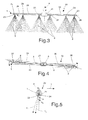
figure 3 diagrammatically shows a longitudinal, side, elevation view of a first embodiment of the device infigure 1 , the washing and/or rinsing jets of water generated by the device in use being highlighted; -
figures 4 and 5 respectively show a plan top view and a cross elevation view of the device infigure 3 ; and -
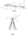
figures 6 and 7 diagrammatically show a top plan view and a cross elevation view, respectively, of a second possible embodiment of the device of the invention. - In figures from 1 to 5, numeral 1 indicates as a whole a washing and/or rinsing device for an
electric household appliance 2, in particular a dishwashing machine for professional use, of the front loading type in the example shown. - The
dishwashing machine 2 specifically comprises awashing chamber 3 accommodating at least one container basket 4 (known) for the dishes 5 to be washed, the washing device 1 and dispensing means 7 of apressurized service fluid 80, e.g. consisting either of washing water possibly with the addition of detergent, or of rinsing water, towards the device 1, in this case towards anoutlet 10 arranged in thewashing chamber 3 with the symmetry axis A thereof arranged substantially vertical and connected to the rinsing device 1 in the manner disclosed below. - The dispensing means 7 of the pressurized water are known and comprise in this case a
pump 11, atank 12 in which the water dispensed in use onto the dishes 5 through theoutlet 10 and the device 1 is collected, and network-water feeding means 13, thepump 11 being able to use both the network-water (during the rinsing cycle) and the water in the tank 12 (during the washing cycle). - The device 1 comprises at least one
arm 20 rotationally mounted about axis A, which is generally vertical, within thewashing chamber 3 of theelectric household appliance 2 immediately over (in the nonlimiting example shown) or under the container basket 4, in this case idly and fluid-tightly mounted, in a known manner and therefore not described in detail for simplicity, to theoutlet 10 by acentral assembly portion 21 thereof. - The
arm 20 delimits acavity 22 therein (figure 4 ) connected in use to the water dispensing means 7 through theoutlet 10 and is provided integral with a plurality of sprayingnozzles corresponding jet 8 of pressurized fluid 80 (e.g. at approximately 0.7 bar). - In particular, the
nozzles first surface 26 of thearm 20, in the shown embodiment the lower surface, which may be either flat, in the case offlat arms 20c, "biscuit"-shaped, or paddle-shaped (figures 6 and 7 ), or curved, in the case of circular- or elliptical-section, tubular arms 20b (figures 2-5 ). In all cases, thesurface 26 is oriented in use towards the dishes 5 and thenozzles surface 26 itself, and are arranged reciprocally spaced lengthwise along thearm 20 and communicating with theinternal cavity 22 of the latter. -
Opposite ends arm 20 extend radially and overhangingly, from opposite sides, from the rotation axis A, which is placed at the middle line of thearm 20, the latter having theassembly portion 21 for securing it to the rotation axis A substantially arranged indeed on the middle line of thearm 20 itself, so that oppositelongitudinal portions arm 20, delimited at the lower part thereof by thesurface 26 and which are provided withnozzles opposite ends assembly portion 21 in the radial direction with respect to rotation axis A. - According to the major aspect of the invention, the
nozzles portion arm 20 by angles α, (e.g. α1, α2 -figure 5 ) progressively increasing with the distance of eachnozzle arm 20 about the rotation axis A (shown infigures 2 to 5 by the arrows), the resultant R of the absolute vectorial speed components Vx,Vy (figure 2 ) of eachjet 8 generated by one of thenozzles - In particular, in
figure 2 , Vx indicates the absolute speed component of eachjet 8 directed parallelly to the angular speed vector of thearm 20, while Vy indicates the absolute speed component of eachjet 8 directed along the axis of thecorresponding nozzle figure 5 , relatively to nozzles 24 - shown - and 25 - not shown as covered by the nozzle 24) in theportion 29 of the arm 20b. R1 indicates the resultant for the jets dispensed by thenozzles nozzle 23, which is the radially farthest from the rotation axis A for bothportions - The rotation angle α, with respect to the mentioned radial plane of the
nozzles longitudinal portion 29 of thearm 20 is opposite to those of the corresponding nozzles carried by thelongitudinal portion 30 of thearm 20. - In the embodiment shown in
figures 2 to 5 , the device 1 is provided with an arm 20b which has a tubular shape with an annular cross section, and thenozzles figure 5 . -
Figures 6 and 7 further show a variant of the device 1, in which the details similar or equivalent to those of the device 1 are shown for simplicity with the same reference numbers, wherein a washing and/orrinsing device 100 comprises anarm 20c which has thenozzles arm 20c in its cross section, the latter having been plastically deformed on the cross plane to the longitudinal axis L of the arm due to a torsion applied about the longitudinal axis L of thearm 20c to a progressively increasing extent with the increase of the distance from the rotation axis A and in a direction such that a front longitudinal edge 33 (figure 7 ) of thearm 20c, orientated in use in a direction agreeing with that of rotation T of thearm 20c itself, is moved away from the dishes. - The
arm 20c, typically a washing arm (while the arm 20b is typically a rinsing arm) has a generally flat shape, substantially a biscuit-shape, being delimited between two reciprocally parallel faces, substantially flat or slightly convex, one of which defines thelower surface 26 of thearm 20c carrying thenozzles - In all cases, according to a first possible alternative embodiment of the invention, the rotation angles α of all the
nozzles arm 20 about the rotation axis A, the resultant R of the absolute vectorial speed components Vx,Vy of eachjet 8 is always substantially parallel to the rotation axis A and, consequently, substantially perpendicular, in use, to the basket 4; in this case, thearm 20 is further provided with at least one further nozzle 40 (figure 7 ) arranged so as to generate a reaction thrust for determining in use the rotation of the arm 20 (thewashing arm 20c in the illustrated case) about the axis A in the predetermined direction T and at a predetermined angular speed (e.g. 60 rpm), for example because it dispenses ajet 41 offluid 80 which is tangentially directed to thearm 20. Obviously, thenozzle 40 will preferably be positioned at one or both of theends - According to another possible alternative embodiment of the invention, the rotation angles α of the
nozzles arm 20 about the rotation axis A, the resultant R1 of the absolute vectorial speed components Vx,Vy of most of thejets 8 generated by the nozzles, in this case those dispensed by thenozzles jet 8 generated by at least one of thenozzles 23 arranged farthest from the rotation axis A, is skew with respect to the rotation axis A by an angle such that a reaction thrust to determine the rotation of the arm 20 (the arm 20b in this case) about the axis A in the predetermined direction T and at a predetermined speed is generated in use. In such a case, along the direction of the speed vector Vx a residual speed component Vr will remain (figure 2 ), not compensated by the direction of the speed vector Vy and thus not null, but however lower than the angular speed vector of thearm 20. - Therefore, the
corresponding jet 8 will not strike the basket 4 perpendicularly to the same, but however at an angle of a few degrees, in all cases noticeably smaller than the incidence angle of the jets generated by the known washing and/or rinsing devices heretofore, thus determining a negligible "drawback" which is in all cases widely compensated by the fact that an appropriate reaction thrust jet for the rotation of thearm 20, such as thejet 41, does not need to be included. - According to a further, possible variant (
figure 6 ), the same result could also be obtained by skewing thejet 8 of at least one of the nozzles 23 (or both) by means of a plastic deformation of theends arm 20 in a circumferential direction, instead of by means of a "reduced" rotation of the corresponding nozzle.
Claims (9)
- A washing and/or rinsing device (1) for an electric household appliance (2), specifically a dishwashing machine, comprising an arm (20) mounted in a rotating manner about and radially overhangingly from a generally vertical axis (A) within a washing chamber (3) of the electric household appliance, immediately either over or under a container basket (4) for dishes (5), the arm delimiting a cavity (22) therein, connected to dispensing means (7) of a pressurized operative fluid (80) and being provided with a plurality of nozzles (23,24,25; 40) arranged reciprocally spaced lengthwise along the arm and communicating with the internal cavity of the latter to eject in use corresponding pressurized jets (8) of operative fluid towards the dishes; characterized in that at least first nozzles (23,24,25) are arranged rotated with respect to a radial plane of the rotation axis (A) passing through a longitudinal symmetry axis (L) of said arm such as to be carried by said arm (20) in different angular positions on the plane of the cross section of the arm itself by angles (α) progressively increasing with the distance of each first nozzle from the rotation axis (A); said angles being chosen so that, having fixed a direction (T) of rotation in use of the arm about the rotation axis, the resultant (R;R1) of the absolute vectorial speed components (Vx,Vy) of each jet (8) generated by a first nozzle is noticeably parallel to the rotation axis (A).
- A device (1) according to claim 1, characterized in that said first nozzles (23,24,25) are carried by the arm on a first surface (26) thereof oriented in use towards the dishes.
- A device (1) according to claim 1 or 2, characterized in that said rotation axis (A) of the arm is positioned in the middle of the arm (20) itself; the latter displaying a mounting portion (21) for securing it to said rotation axis (A) essentially arranged in the middle of the arm itself, so that a first and second opposite longitudinal portions (29,30) of the arm, delimited at least in part by said first surface (26) provided with said nozzles and ending with opposite free ends (27,28) of the arm, protrude in use in an essentially symmetric manner from the mounting portion (21) in a radial direction with respect to the rotation axis (A); the rotation angle (α) with respect to said radial plane of the first nozzles (23,24,25) carried by the first longitudinal portion (29) of the arm being opposite to those of the first nozzles carried by the second longitudinal portion (30) of the arm.
- A device (1) according to any one of the preceding claims, characterized in that said arm (20b) displays a tubular shape with annular cross section, said first nozzles being integrally carried by the arm in different angular positions on the plane of said cross section of the arm.
- A device (1) according to any one of the preceding claims from 1 to 3, characterized in that said arm (20c) displays said first nozzles all arranged reciprocally aligned and parallel to the longitudinal axis (L) of the arm in its cross section, the latter having been plastically deformed on the cross plane to the longitudinal axis (L) of the arm by effect of a torsion applied about the longitudinal axis of the arm to a progressively increasing extent to the increase of the distance from the rotation axis and in such a direction to move a front longitudinal edge (33) of the arm orientated in use in a direction agreeing with that of rotation (T) of the arm away from the dishes.
- A device (1) according to claim 5, characterized in that said arm (20c) displays a generally flat shape, essentially biscuit-shaped, being delimited between two reciprocally parallel faces, essentially flat or slightly convex, one of which defines said first surface (26) of the arm.
- A device (1) according to claim 6, characterized in that said rotation angles (α) of said first nozzles are chosen so that, having fixed a direction of rotation (T) in use of the arm (20) about the rotation axis (A), the resultant (R) of the absolute vectorial speed components of each jet (8) generated by a first nozzle (23,24,25) is essentially parallel to the rotation axis and, consequently, in use, essentially perpendicular to the basket (4); said arm (20c) being further provided with at least one second nozzle (40) arranged so as to generate a reaction thrust to determine in use the rotation of the arm about said axis (A) in a predetermined direction and at a predetermined speed.
- A device (1) according to any of the preceding claims, characterized in that said rotation angles (α) of the first nozzles (23,24,25) are chosen so that, having fixed a direction (T) of rotation in use of the arm about the rotation axis, the resultant (R1) of the absolute vectorial speed components of most of the jets (8) generated by a first nozzle is, in use, essentially parallel to the rotation axis (A) and, consequently, essentially perpendicular to the basket; and that of the jet generated by at least one first nozzle (23), preferably the farthest from the rotation axis (A), is skew with respect to the rotation axis (A) by an angle such as to generate in use a reaction thrust such as to determine the rotation of the arm about said axis (A) in a predetermined direction and at a predetermined speed.
- An electric household appliance (2), specifically a front-loading dishwashing machine, comprising a washing chamber (3) accommodating at least one container basket (4) for the dishes (5) to be washed, and dispensing means (7) of a pressurized service fluid (8), e.g. washing and/or rinsing water, towards an outlet (10) arranged in the washing chamber (3) with an essentially vertical symmetric axis (A) thereof, characterized in that it comprises a device (1) according to any of claims from 1 to 8, wherein the arm (20) is idly and fluid-tightly mounted on said outlet (10) with a central mounting portion (21) thereof, immediately either over or under said basket (4).
Applications Claiming Priority (1)
| Application Number | Priority Date | Filing Date | Title |
|---|---|---|---|
| IT000881A ITTO20070881A1 (en) | 2007-12-05 | 2007-12-05 | IMPROVED WASHING AND / OR RINSING DEVICE AND DISHWASHER MACHINE INCLUDING THIS DEVICE |
Publications (3)
| Publication Number | Publication Date |
|---|---|
| EP2067428A2 EP2067428A2 (en) | 2009-06-10 |
| EP2067428A3 EP2067428A3 (en) | 2011-11-30 |
| EP2067428B1 true EP2067428B1 (en) | 2014-11-19 |
Family
ID=40315879
Family Applications (1)
| Application Number | Title | Priority Date | Filing Date |
|---|---|---|---|
| EP08170772.1A Not-in-force EP2067428B1 (en) | 2007-12-05 | 2008-12-05 | Improved washing and/or rinsing device, and dishwashing machine featuring such a device |
Country Status (4)
| Country | Link |
|---|---|
| US (1) | US20090145468A1 (en) |
| EP (1) | EP2067428B1 (en) |
| AU (1) | AU2008255150B2 (en) |
| IT (1) | ITTO20070881A1 (en) |
Cited By (3)
| Publication number | Priority date | Publication date | Assignee | Title |
|---|---|---|---|---|
| US11026555B2 (en) | 2015-12-21 | 2021-06-08 | Electrolux Appliances Aktiebolag | Dishwasher comprising a wash arm arrangement |
| US11464390B2 (en) | 2017-10-31 | 2022-10-11 | Electrolux Appliances Aktiebolag | Fan-shaped spray detergent nozzle |
| US12390081B2 (en) | 2020-07-22 | 2025-08-19 | Samsung Electronics Co., Ltd. | Dishwasher |
Families Citing this family (31)
| Publication number | Priority date | Publication date | Assignee | Title |
|---|---|---|---|---|
| DE102015207588A1 (en) * | 2015-04-24 | 2016-10-27 | BSH Hausgeräte GmbH | Spray arm assembly and dishwasher |
| WO2018072165A1 (en) * | 2016-10-20 | 2018-04-26 | 李良学 | Spray rinsing apparatus for construction column and method for using same |
| US10524634B2 (en) | 2017-09-29 | 2020-01-07 | Midea Group Co., Ltd. | Dishwasher with combined liquid and air sprayers |
| US10531781B2 (en) | 2017-09-29 | 2020-01-14 | Midea Group Co., Ltd. | Dishwasher with discretely directable tubular spray elements |
| US12290225B2 (en) | 2017-09-29 | 2025-05-06 | Midea Group Co., Ltd. | Dishwasher with walking tubular spray element |
| WO2019086106A1 (en) | 2017-10-31 | 2019-05-09 | Electrolux Appliances Aktiebolag | Spray arm assembly |
| WO2019086107A1 (en) | 2017-10-31 | 2019-05-09 | Electrolux Appliances Aktiebolag | Wash arm assembly |
| CN108324209A (en) * | 2018-03-21 | 2018-07-27 | 苏州路之遥科技股份有限公司 | A kind of spray angle gradual change type intelligent tool cleaning device |
| US11071440B2 (en) | 2018-09-14 | 2021-07-27 | Midea Group Co., Ltd. | Dishwasher with rack-mounted conduit return mechanism |
| US10631708B2 (en) | 2018-09-14 | 2020-04-28 | Midea Group Co., Ltd. | Dishwasher with docking arrangement for elevation-adjustable rack |
| US10765291B2 (en) | 2018-09-14 | 2020-09-08 | Midea Group Co., Ltd. | Dishwasher with check valve in rotatable docking port |
| US11000176B2 (en) | 2018-09-14 | 2021-05-11 | Midea Group Co., Ltd. | Dishwasher with rotatable diverter valve |
| US11045066B2 (en) | 2019-03-11 | 2021-06-29 | Midea Group Co., Ltd. | Dishwasher with keyed coupling to rack-mounted conduit |
| US11399690B2 (en) | 2019-09-30 | 2022-08-02 | Midea Group Co., Ltd. | Dishwasher with cam-based position sensor |
| US11484183B2 (en) | 2019-09-30 | 2022-11-01 | Midea Group Co., Ltd. | Dishwasher with image-based object sensing |
| US11464389B2 (en) | 2019-09-30 | 2022-10-11 | Midea Group Co., Ltd. | Dishwasher with image-based detergent sensing |
| US11191416B2 (en) | 2019-09-30 | 2021-12-07 | Midea Group Co., Ltd. | Dishwasher with image-based position sensor |
| US11026559B2 (en) | 2019-09-30 | 2021-06-08 | Midea Group Co., Ltd. | Dishwasher with image-based fluid condition sensing |
| US11259681B2 (en) | 2019-09-30 | 2022-03-01 | Midea Group Co., Ltd | Dishwasher with image-based diagnostics |
| CN112775067B (en) * | 2019-11-08 | 2022-10-28 | 上海至纯洁净系统科技股份有限公司 | Quick-discharging mechanical arm clamping hand cleaning tank |
| US11185209B2 (en) | 2019-11-20 | 2021-11-30 | Midea Group Co., Ltd. | Dishwasher steam generator |
| US11202550B2 (en) | 2019-11-20 | 2021-12-21 | Midea Group Co., Ltd. | Dishwasher thermal imaging system |
| US11497374B2 (en) | 2020-02-19 | 2022-11-15 | Midea Group Co., Ltd. | Dishwasher with wall-mounted rotatable conduit |
| US11412912B2 (en) | 2020-09-21 | 2022-08-16 | Midea Group Co., Ltd. | Dishwasher with tubular spray element slip ring alignment |
| US11484180B2 (en) | 2020-11-11 | 2022-11-01 | Midea Group Co., Ltd. | Dishwasher with tubular spray element including multiple selectable spray patterns |
| US11826001B2 (en) | 2022-02-15 | 2023-11-28 | Midea Group Co., Ltd. | Dishwasher with tubular spray element including elongated metal tube and retaining tab for mounting support member thereto |
| US12245735B2 (en) | 2022-02-25 | 2025-03-11 | Midea Group Co., Ltd. | Dishwasher including tubular spray element with intermediate support and/or fluid inlet |
| EP4252611A1 (en) * | 2022-03-31 | 2023-10-04 | D&P S.r.l. | Dishwashing machine |
| US12329341B2 (en) | 2023-06-28 | 2025-06-17 | Midea Group Co., Ltd. | Dishwasher with rack-mounted tubular spray element assembly |
| WO2025044333A1 (en) * | 2023-09-01 | 2025-03-06 | 佛山市顺德区美的洗涤电器制造有限公司 | Spray arm assembly and dishwasher |
| US20250353041A1 (en) * | 2024-05-16 | 2025-11-20 | Derek Allen | Washing vessel for arrestor from oil and gas heater treater and method of use |
Family Cites Families (8)
| Publication number | Priority date | Publication date | Assignee | Title |
|---|---|---|---|---|
| US2021962A (en) * | 1934-01-23 | 1935-11-26 | Henry J Carlton | Dishwashing machine |
| US3292645A (en) * | 1964-10-13 | 1966-12-20 | Gen Motors Corp | Reaction spray dishwasher having an improved water fill system |
| US3294102A (en) * | 1964-12-09 | 1966-12-27 | Whirlpool Co | Dishwashing apparatus having improved pump means |
| US4187122A (en) * | 1978-11-07 | 1980-02-05 | Query Grady W | Dishwashing apparatus |
| IT248022Y1 (en) | 1999-05-03 | 2002-12-09 | Electrolux Zanussi Elettrodome | DISHWASHER WITH EPICYCLOIDAL SPRAY REEL |
| ITTO20010943A1 (en) * | 2001-10-05 | 2003-04-05 | Elbi Int Spa | DEVIATION VALVE UNIT, ESPECIALLY FOR A DISHWASHER-DISHWASHING MACHINE. |
| KR100457574B1 (en) * | 2002-11-28 | 2004-11-18 | 엘지전자 주식회사 | Nozzle of dish washer |
| US20050230502A1 (en) * | 2004-03-31 | 2005-10-20 | Electrolux Home Products, Inc. | Spray devices and nozzles |
-
2007
- 2007-12-05 IT IT000881A patent/ITTO20070881A1/en unknown
-
2008
- 2008-12-05 US US12/329,117 patent/US20090145468A1/en not_active Abandoned
- 2008-12-05 AU AU2008255150A patent/AU2008255150B2/en not_active Ceased
- 2008-12-05 EP EP08170772.1A patent/EP2067428B1/en not_active Not-in-force
Cited By (3)
| Publication number | Priority date | Publication date | Assignee | Title |
|---|---|---|---|---|
| US11026555B2 (en) | 2015-12-21 | 2021-06-08 | Electrolux Appliances Aktiebolag | Dishwasher comprising a wash arm arrangement |
| US11464390B2 (en) | 2017-10-31 | 2022-10-11 | Electrolux Appliances Aktiebolag | Fan-shaped spray detergent nozzle |
| US12390081B2 (en) | 2020-07-22 | 2025-08-19 | Samsung Electronics Co., Ltd. | Dishwasher |
Also Published As
| Publication number | Publication date |
|---|---|
| AU2008255150B2 (en) | 2010-08-05 |
| EP2067428A2 (en) | 2009-06-10 |
| AU2008255150A1 (en) | 2009-06-25 |
| US20090145468A1 (en) | 2009-06-11 |
| EP2067428A3 (en) | 2011-11-30 |
| ITTO20070881A1 (en) | 2009-06-06 |
Similar Documents
| Publication | Publication Date | Title |
|---|---|---|
| EP2067428A2 (en) | Improved washing and/or rinsing device, and dishwashing machine featuring such a device | |
| US20090101185A1 (en) | Low-water-consumption rinsing and/or washing device, and dishwashing machine featuring such a device | |
| EP3030131B1 (en) | A dishwasher with improved washing effectiveness | |
| EP3122228B1 (en) | Dishwasher comprising at least one dishwasher spray arm | |
| EP1626819B1 (en) | A parts washer | |
| CN104271024A (en) | Device for moving a washing impeller for a washing device and/or a drying device | |
| EP3266361B1 (en) | Spray arm assembly for dishwasher, and dishwasher | |
| EP3393327B1 (en) | Dishwasher comprising a wash arm arrangement | |
| KR101461390B1 (en) | Drum washing machine | |
| ITMI992054A1 (en) | REVOLVING SPRAYER FOR DISHWASHER EQUIPPED WITH DEVICE FOR HORIZONTAL MOVEMENT | |
| WO2017211393A1 (en) | Improved spray means for use in a dishwasher | |
| CN101347317B (en) | Dish washer | |
| KR102058071B1 (en) | Dishwasher | |
| EP2242413B1 (en) | Low-water-consumption rinsing and/or washing device, and dishwashing machine featuring such a device | |
| JP2011250920A5 (en) | ||
| JPH07250799A (en) | Dishwasher | |
| EP2961878B1 (en) | Washing machine water jet nozzle | |
| KR102322060B1 (en) | Ultrasonic washing machine | |
| KR100701168B1 (en) | Dishwashing Water Dispenser of Dishwasher | |
| EP3791768B1 (en) | A dishwasher with improved washing effectiveness | |
| EP3874083B1 (en) | A washing machine | |
| AU2004229589B2 (en) | A parts washer | |
| JP2002065559A (en) | Dishwasher | |
| JP2006198052A (en) | Dishwasher |
Legal Events
| Date | Code | Title | Description |
|---|---|---|---|
| PUAI | Public reference made under article 153(3) epc to a published international application that has entered the european phase |
Free format text: ORIGINAL CODE: 0009012 |
|
| AK | Designated contracting states |
Kind code of ref document: A2 Designated state(s): AT BE BG CH CY CZ DE DK EE ES FI FR GB GR HR HU IE IS IT LI LT LU LV MC MT NL NO PL PT RO SE SI SK TR |
|
| AX | Request for extension of the european patent |
Extension state: AL BA MK RS |
|
| RIC1 | Information provided on ipc code assigned before grant |
Ipc: A47L 15/23 20060101ALI20110906BHEP Ipc: A47L 15/22 20060101AFI20110906BHEP |
|
| PUAL | Search report despatched |
Free format text: ORIGINAL CODE: 0009013 |
|
| AK | Designated contracting states |
Kind code of ref document: A3 Designated state(s): AT BE BG CH CY CZ DE DK EE ES FI FR GB GR HR HU IE IS IT LI LT LU LV MC MT NL NO PL PT RO SE SI SK TR |
|
| AX | Request for extension of the european patent |
Extension state: AL BA MK RS |
|
| RIC1 | Information provided on ipc code assigned before grant |
Ipc: A47L 15/23 20060101ALI20111025BHEP Ipc: A47L 15/22 20060101AFI20111025BHEP |
|
| 17P | Request for examination filed |
Effective date: 20120530 |
|
| AKX | Designation fees paid |
Designated state(s): DE FR GB IT |
|
| GRAP | Despatch of communication of intention to grant a patent |
Free format text: ORIGINAL CODE: EPIDOSNIGR1 |
|
| INTG | Intention to grant announced |
Effective date: 20140604 |
|
| GRAS | Grant fee paid |
Free format text: ORIGINAL CODE: EPIDOSNIGR3 |
|
| GRAA | (expected) grant |
Free format text: ORIGINAL CODE: 0009210 |
|
| AK | Designated contracting states |
Kind code of ref document: B1 Designated state(s): DE FR GB IT |
|
| REG | Reference to a national code |
Ref country code: GB Ref legal event code: FG4D |
|
| REG | Reference to a national code |
Ref country code: DE Ref legal event code: R096 Ref document number: 602008035432 Country of ref document: DE Effective date: 20141231 |
|
| REG | Reference to a national code |
Ref country code: DE Ref legal event code: R026 Ref document number: 602008035432 Country of ref document: DE |
|
| PLBI | Opposition filed |
Free format text: ORIGINAL CODE: 0009260 |
|
| PLAX | Notice of opposition and request to file observation + time limit sent |
Free format text: ORIGINAL CODE: EPIDOSNOBS2 |
|
| 26 | Opposition filed |
Opponent name: BELIMED AG Effective date: 20150819 |
|
| GBPC | Gb: european patent ceased through non-payment of renewal fee |
Effective date: 20150219 |
|
| REG | Reference to a national code |
Ref country code: FR Ref legal event code: PLFP Year of fee payment: 8 |
|
| PG25 | Lapsed in a contracting state [announced via postgrant information from national office to epo] |
Ref country code: IT Free format text: LAPSE BECAUSE OF FAILURE TO SUBMIT A TRANSLATION OF THE DESCRIPTION OR TO PAY THE FEE WITHIN THE PRESCRIBED TIME-LIMIT Effective date: 20141119 |
|
| PLAF | Information modified related to communication of a notice of opposition and request to file observations + time limit |
Free format text: ORIGINAL CODE: EPIDOSCOBS2 |
|
| PG25 | Lapsed in a contracting state [announced via postgrant information from national office to epo] |
Ref country code: GB Free format text: LAPSE BECAUSE OF NON-PAYMENT OF DUE FEES Effective date: 20150219 |
|
| PLBB | Reply of patent proprietor to notice(s) of opposition received |
Free format text: ORIGINAL CODE: EPIDOSNOBS3 |
|
| REG | Reference to a national code |
Ref country code: FR Ref legal event code: PLFP Year of fee payment: 9 |
|
| REG | Reference to a national code |
Ref country code: DE Ref legal event code: R100 Ref document number: 602008035432 Country of ref document: DE |
|
| PLCK | Communication despatched that opposition was rejected |
Free format text: ORIGINAL CODE: EPIDOSNREJ1 |
|
| PLBN | Opposition rejected |
Free format text: ORIGINAL CODE: 0009273 |
|
| STAA | Information on the status of an ep patent application or granted ep patent |
Free format text: STATUS: OPPOSITION REJECTED |
|
| REG | Reference to a national code |
Ref country code: FR Ref legal event code: PLFP Year of fee payment: 10 |
|
| 27O | Opposition rejected |
Effective date: 20170705 |
|
| PGFP | Annual fee paid to national office [announced via postgrant information from national office to epo] |
Ref country code: FR Payment date: 20191226 Year of fee payment: 12 |
|
| PGFP | Annual fee paid to national office [announced via postgrant information from national office to epo] |
Ref country code: DE Payment date: 20191231 Year of fee payment: 12 |
|
| REG | Reference to a national code |
Ref country code: DE Ref legal event code: R119 Ref document number: 602008035432 Country of ref document: DE |
|
| PG25 | Lapsed in a contracting state [announced via postgrant information from national office to epo] |
Ref country code: FR Free format text: LAPSE BECAUSE OF NON-PAYMENT OF DUE FEES Effective date: 20201231 |
|
| PG25 | Lapsed in a contracting state [announced via postgrant information from national office to epo] |
Ref country code: DE Free format text: LAPSE BECAUSE OF NON-PAYMENT OF DUE FEES Effective date: 20210701 |