EP2067069B1 - Device and method for thermally connecting optical fibers - Google Patents
Device and method for thermally connecting optical fibers Download PDFInfo
- Publication number
- EP2067069B1 EP2067069B1 EP07820975.6A EP07820975A EP2067069B1 EP 2067069 B1 EP2067069 B1 EP 2067069B1 EP 07820975 A EP07820975 A EP 07820975A EP 2067069 B1 EP2067069 B1 EP 2067069B1
- Authority
- EP
- European Patent Office
- Prior art keywords
- offset
- optical waveguide
- welding time
- memory
- attenuation
- Prior art date
- Legal status (The legal status is an assumption and is not a legal conclusion. Google has not performed a legal analysis and makes no representation as to the accuracy of the status listed.)
- Expired - Fee Related
Links
Images

Classifications
-
- G—PHYSICS
- G02—OPTICS
- G02B—OPTICAL ELEMENTS, SYSTEMS OR APPARATUS
- G02B6/00—Light guides; Structural details of arrangements comprising light guides and other optical elements, e.g. couplings
- G02B6/24—Coupling light guides
- G02B6/255—Splicing of light guides, e.g. by fusion or bonding
- G02B6/2551—Splicing of light guides, e.g. by fusion or bonding using thermal methods, e.g. fusion welding by arc discharge, laser beam, plasma torch
-
- G—PHYSICS
- G01—MEASURING; TESTING
- G01M—TESTING STATIC OR DYNAMIC BALANCE OF MACHINES OR STRUCTURES; TESTING OF STRUCTURES OR APPARATUS, NOT OTHERWISE PROVIDED FOR
- G01M11/00—Testing of optical apparatus; Testing structures by optical methods not otherwise provided for
- G01M11/30—Testing of optical devices, constituted by fibre optics or optical waveguides
- G01M11/37—Testing of optical devices, constituted by fibre optics or optical waveguides in which light is projected perpendicularly to the axis of the fibre or waveguide for monitoring a section thereof
Definitions
- the invention relates to the field of connecting optical waveguides. More particularly, the invention relates to a device for connecting ends of optical fibers by means of a thermal process. The invention also relates to a corresponding method.
- Devices for connecting optical waveguides by means of heat are generally known.
- the fiber ends of the optical fibers to be spliced are heated so that they can fuse together. It is desired that the resulting attenuation of the splice is as low as possible.
- the fiber ends to be spliced are aligned and the splicing is adapted to the circumstances caused by the environment to the given effort the lowest possible due to the splice attenuation for in the fiber to achieve spreading light.
- an arc, a glow discharge, a laser beam or a resistance wire in the form of, for example, a heating coil can be used.
- splicing devices are in demand, which are inexpensive, can be produced and in the application as reliable as possible, easy to use and low maintenance, yet the Quality of the splice connection produced should meet the highest possible standards.
- Such devices are used, for example, to install optical fibers in buildings or to connect the buildings via fiber-optic cables to the existing network. Characteristic of such devices is a low weight, the simplest and most robust mechanics and electronics in the device and the highest possible degree of automation during the generation of the splice.
- a splicer that uses each other to align the fiber ends electromechanical motors, such as stepper motors and a mechanical reduction.
- the stepper motors and the reduction are available at low cost, but compromises in the positioning accuracy of this mechanism must be accepted.
- a residual offset in the viewing direction remains perpendicular to the longitudinal axis of the optical waveguides in the rule. Due to the limited accuracy of said positioning on the order of about 1 micron (microns), an exact alignment of the fibers can only be achieved by chance, in general, a residual offset remains.
- the welding process is performed on such devices with fixed welding current at a fixed welding time. This setting has been set to optimal only for a typical initial offset so that deviating initial offset values are not treated individually. In particular, no adaptation of the welding parameters is made.
- Conventional splicer for example, as in the US 6,230,522 use an offset reduction to adjust the device and its splice parameters to accommodate a splice environment, and retain it set parameter set for the control of the next splicing operation and further splicing operations unchanged. For this purpose, a defined distance of the fibers to be joined of a test splice is set, the fiber ends are heated, and a remaining residual offset of the connected fibers is determined. An association that indicates a current correction as a function of a remaining residual offset can be stored in the device. Therefore, these devices require complex acquisition and alignment electronics and a sophisticated mechanism to always ensure that at the beginning of the normal splicing process, the optical fibers are aligned as accurately as possible and reproducible to each other. Such elaborate positioning systems use, for example piezoelectric elements based on piezoelectric ceramics, which allow positioning of the cores of the glass fibers to be welded in two axes.
- Another conventional splicer is in the GB 2 420 633 described.
- the device according to the invention is defined in claim 1, the method according to the invention in claim 8.
- an apparatus for thermally connecting respective ends of at least two optical fibers comprises: each a positioning device associated with one of the optical fibers, by which the ends are brought relative to each other into a position that enables a thermally induced bonding; an observation device by which a relative displacement of the ends of the optical fibers to be connected is determined; a memory through which a predetermined relationship between a possible offset and a parameter controlling the effect of heat; a thermal means by which the joining of the ends of the optical fibers in response to a value output from the memory is effected.
- the device accepts an initial residual offset of the optical fiber ends to be spliced.
- corresponding positioning elements can be provided with grooves in which the fiber ends are stored.
- the grooves may be positionally fixed to each other. It is also possible that a certain coarse alignment of the fiber ends takes place, the positioning accuracy nevertheless being such, for example in the range from greater than approximately 1 ⁇ m to 10 ⁇ m, that a lateral offset of the fiber ends is to be expected.
- the device now detects the offset of the outer contours of the optical waveguides according to the exemplary embodiment before the optical waveguides are welded together, and then determines optimal control of one or more parameters of the splicing process on the basis of a predetermined relationship stored in the device. For example, when using an arc splicer, the welding time, such as the operating time during which the arc is active, is determined based on the relationship stored in the device, depending on the determined offset. Additionally or alternatively, the current intensity for supplying the arc electrodes can be adjusted.
- the manufacturer or a user adjustable to a desired for the splicing connection required damping set on the device.
- the device automatically determines the optimum welding time from the relationship stored in the device memory due to a measured offset of the optical waveguides before the connection process.
- various relationships, each associated with a desired damping to be given stored in the device and are activated according to the specification by the manufacturer or operator accordingly.
- Different attenuations require different welding current strengths, so that the cached relationships are parameterized according to the attenuation or the welding current intensity. This may mean that an assigned relationship of the type mentioned is stored for each given welding current intensity.
- the stored predetermined relationship between the possible offset of the outer contours of the still unconnected optical waveguide before welding and the splice parameter dependent thereon, for example, the supply current of the heating device of the splicer, may be stored in the form of a look-up table or in the form of a calculation rule, such as a calculation formula, such as in Form of an equation for a straight line or another mathematical curve.
- a method for thermally connecting respective ends of at least two optical fibers comprises: positioning the ends of the at least two optical fibers relative to each other, so that a connection is made possible by the action of heat; Taking a picture of the ends of the at least two optical fibers; Determining an offset between the ends of the at least two optical fibers; Outputting a value for a parameter from a memory providing a dependency between a possible offset and a parameter affecting the effect of heat; Driving a heat source in dependence on the value for the parameter to connect the ends of the at least two optical fibers.
- FIG. 1 splicer shown is used to connect the ends of two optical fibers 100, 101, which may be optical fibers, by thermal action with each other.
- a glow discharge zone or arc zone 303 is generated, which melts the mutually opposite ends of the optical waveguides.
- the optical fibers are moved towards each other and thereby connect.
- the optical waveguides are, for example, glass fibers with one or more light-guiding cores.
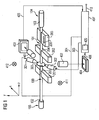
- the fiber end 100 originates from an optical waveguide 105 which is surrounded by a sheath 102 which has been removed at the end 100, so that essentially only the light-conducting fiber core 107 is surrounded by the glass sheath 106 with different refractive index (FIG. FIG. 2 ) is present.
- Suitable optical waveguides are all known types of optical waveguides, but in particular single-mode fibers or NZDS fibers (non-zero dispersion-shifted fibers).
- the optical fibers may be optical fibers such as glass fibers.
- Positioning devices 201, 202 have respective grooves 203 and 204, respectively, in which the fiber ends are deposited.
- the positioning elements 201, 202 and thus the grooves 203, 204 may, in one embodiment, be largely fixed in position in the device. Then these grooves are preferably aligned substantially exactly to each other.
- the V-shaped grooves for example, in ceramics be ground or etched in silicon and are thus manufactured due to fractions of microns against each other. Nevertheless, then, the surfaces 110, 111 of the fiber ends facing one another may be offset with respect to one another, for example because the fibers may have a different diameter and therefore lie at different heights in the normally V-shaped groove.
- the fiber ends may be dirty or the grooves may be contaminated by dust particles.
- frozen stresses in one of the fibers or fibers exerted on the fibers by hold-down mechanisms may result in misalignment and location as in FIG FIG. 2 shown lead.
- An offset of the fiber ends to be welded generally also exists if the positioning elements 201, 202 are not completely fixed, but are displaceable relative to one another by means of an adjusting device which only offers a coarse adjustment possibility, for example in the range of greater than 1 micrometer ( ⁇ m ) lies.
- the positioning devices 201, 202 may, as in the DE 102005038937.6 be executed and may include an electrically operated stepper motor, which generates a displacement possibility in the x-direction by means of a spindle or other transmission gear from the engine revolution.
- connection of spindle / gear and stepping motor currently has a relatively high positioning accuracy, which is less accurate than the achievable with a piezoceramic positioning accuracy, which is in the order of about 0.06 microns to 0.1 microns.
- the named Stepper motor mechanics provide a positioning accuracy of 1 ⁇ m at the lowest and typically 5 to 6 ⁇ m.
- the splicer in FIG. 1 now has a respective camera in x-direction and y-direction 401 and 402, through which the environment within the glow discharge zone 303 can be detected imagewise.
- the cameras 401, 402 are for example Charged Coupled Devices (CCD), which capture an image resolved into pixels and provide them digitally.
- Respective light sources 411, 412 are associated with the CCD arrays 401, 402, respectively, and illuminate the glow discharge zone 303.
- the cameras 401, 402 generate respective positional images 403 and 404, respectively, which are evaluated in a controller 407 of the splicing device, which is developed, for example, by a microprocessor.
- positional images of the fiber ends are taken from two different directions. In the FIG. 1 These are the x-direction and the y-direction, which are at 90 degrees to each other. The directions can also include a different angle.
- a corresponding optics such as a mirror optics, the light beams generated by the light sources 411, 412 on the glow discharge zone 303 so that the recording of images of the fiber ends from two different directions through the one of the cameras is recorded.
- one of the images is captured in one part of the camera, the other of the images in another part of the camera.
- Corresponding optics are sufficiently known to those skilled in the art, so that they will not be explained in detail here.
- the splicer furthermore has a displacement device 205, which can effect a displacement along the z-direction of the fibers, ie in the fiber longitudinal direction 206. This is necessary when the welding operation is already in progress and the fused ends of the optical fibers are telescoped during the welding operation to create some overlap and to compensate for material loss due to the heating process or missing glass material due to non-ideal faces.
- the positioning accuracy along the direction 206 is relatively uncritical in terms of accuracy.
- a value for a parameter is now determined, as described in more detail below, of the electrodes 301 via couplings 304, 305 or 302 drives.
- the amount of current, for example the duration of the power supply, of the current supplied to the electrodes 301, 302 is controlled via the couplings 304, 305.
- the supplied current is converted via the glow discharge generated by the electrodes 301, 302 or the generated arc into a quantity of heat available for welding the fiber ends.
- no offset is present or the offset is so low that a desired resulting attenuation of the light propagation in the optical waveguide is achieved or falls below a specified maximum attenuation becomes.
- a constant predetermined current strength is the couplings 304, 305, the period during which the current is supplied, so controlled the welding time.
- the optimization can take place in different steps.
- Experience has shown that in order not to exceed a desired maximum damping of the splice connection to be generated, a correspondingly suitable current intensity is required.
- the input of maximum attenuation at port 413 may be factory set once or may be specified by the operator of the device as needed via manual input.
- the control information for the active connections 304, 306 and the splice time is then provided by the context stored in the control device 407.
- the offset D1 of the outer contours 108, 109 of the optical fiber ends 100, 101 is determined. Since the device detects the offset from two different directions, for example x and y directions, which are offset at an acute angle, preferably 90 degrees to each other, a total offset derived therefrom is determined. For example, in the case of 90 degrees offset observation directions, the total offset is determined by rooting from the sum of the squares of the measured offset values associated with the x and y directions, respectively.
- the offset D1 between the outer contours 108, 109 is detected.
- the residual offset D1 is partially or completely compensated by the self-centering effect of the material and surface forces.
- the fibers still have an offset D2 running in the z-direction between the front ends 110, 111 of the optical waveguides. This offset is compensated during the welding operation by the z-positioning device 205, whereby even an overlap of the fiber ends is generated.
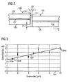
- the relationship between fiber offset and welding time stored in the control device 407 can, as in FIG FIG. 3 represented represented represented.
- the horizontal axis 501 represents the possible values of fiber displacement expected in practice, while a correspondingly assigned welding time can be read on the vertical axis 502.
- the illustrated relationship is shown in the form of a curve, in this case a straight line 503, which was determined on the basis of individual measured values or empirical values 504a, 504b, 504c, etc., as a compensation straight line.
- the present fibers to be fused are, for example, 0.1 micron eccentricity SMF 1528 fibers from Corning, Incorporated.
- the straight line 503 was determined for a welding current of 14.0 mA.
- Another desired maximum target damping may require another welding current.
- the straight line associated with such another welding current will generally have a different vertical position and a different slope than those in FIG FIG. 3 shown straight line. For example, there is one Due to measured values, the straight line for a welding current of 13.0 mA in the graph above the straight line 503 has a greater gradient than the straight line 503. Due to the fiber offset determined in a specific case, it is then possible to use the straight line or the desired damping is assigned to the predetermined current, the optimum welding time can be determined. The actual measured fiber offset serves as input value, the welding time is determined on the basis of the straight line and output as output value.
- the shown straight lines are determined on the basis of preliminary tests.
- a splicer is used in which a predetermined offset between the fibers is adjustable.
- the predetermined offset is adjusted and the integrated autofusion time control can in each case determine the optimum welding time.
- the averaged optimum weld times, which result from achieving the lowest attenuation, are assigned to the corresponding offset values at intervals of 1.0 ⁇ m as values 504a, 504b,..., 504c (FIG. FIG. 3 ). From this, the balancing line 503 is determined.
- the straight 503 in FIG. 4 corresponds to the straight line 503 FIG. 3 ,
- Straight line 505 is designed for a splicing current of 13.0 mA.
- the straight line 506 is intended for a welding current of 15.0 mA. It can be seen that with a welding current of, for example, 14.0 mA, the optimum welding time increases from 3 seconds to about 5 seconds as the fiber offset increases from 0 ⁇ m to 6 ⁇ m. With a reduced welding current of 13.0 mA, the extension of the optimum welding time is greater.
- the straight line 505 is therefore above, ie at higher values for the welding time compared to the straight line 503. At a fiber offset of 6 ⁇ m, the welding time is 9 seconds with a welding current of 13.0 mA.
- a further reduction of the attenuation of the finished splice connection in particular with larger fiber offsets, can be achieved with a reduced welding current.
- Such a further reduction of the damping at larger fiber offsets is associated with an extension of the welding time.
- using a higher splice current results in higher attenuation for large fiber offsets. Therefore, in one embodiment, a certain attenuation threshold is set that is to be achieved for the splices. The attenuation value is entered on the device via port 413.
- the welding current must be suitably adjusted. For example, at port 413, damping is entered by the operator or factory programmed for use. A suitable welding current to achieve a given maximum damping depends on the initial detected offset of the fibers. It is generally more favorable to use a high welding current at a lower offset and to use a lower welding current for a larger offset. A higher welding current simultaneously reduces the welding time. It therefore makes sense to set a certain attenuation threshold that should be reached for all splices. Now, if an initial offset is determined for which the desired damping is not achievable with the currently set welding current, another welding current is adjusted accordingly and thus another of the in FIG.
- this control may include setting a high splice current for low initial offset values, setting a mean splice current for medium offset values, and setting a lower splice current for high offset values. Summarized in a value table, this results in: offset welding current ⁇ 5 ⁇ m 15.0 mA 6 ... 7 ⁇ m 14.0 mA ⁇ 8 ⁇ m 13.0 mA
- the required welding time is determined accordingly.
- a control characteristic is used in which, depending on the detected initial offset, the splice current to be adjusted gradually decreases.
- the in FIG. 3 Ideally illustrated context in the controller 407 in a memory 420 there, for example, as a table as in FIG. 5 stored stored. Corresponding tables (not shown separately) are in memory 420 for curves 505, 506 of FIG FIG. 4 stored.
- the memory 420 contains, for example, various discrete input values 0... 10 in the unit .mu.m, to each of which a welding time 3.0... 6.2 in the unit s (seconds) is assigned.
- the context needs a as in FIG. 3 be shown degrees 503. It can be a curve of any higher order or entirely based on empirical values be set curve. If the offset determined by the images 403, 404 is between two stored values for the fiber offset, interpolation is required.
- a calculation rule can also be stored in memory 420.
- Corresponding calculation instructions are possible for the curves 505, 506 in each case.
- the respectively named total offset is determined from the images 403 and 404 recorded along the x-direction and along the y-direction and used as input for the context stored in the memory 420 and stored there either as an input value of the table (left column of FIG. 5 ) or as the input value for the calculation rule, so that a welding time in seconds is determined from this.
- the controller 407 and couplings 304, 305 energize the welding current to the level of, for example, 14.0 milliamps (mA) to connect SMF 1528 optical fiber ends to the electrodes 301, 302 during this welding time.
- mA milliamps
- the memory 420 stores a plurality of different welding currents of assignable relationships. Depending on the specification of a desired welding current, one of these relationships is selected for the described control process.
- a laser device may be used, for example with a laser diode.
- a laser beam is generated and deflected by means of optics, so that it supplies the splice with thermal power, so that the welding of the fiber ends is made possible.
- the operating time of the laser is determined on the basis of the relationship stored in the memory 420 on the basis of the established residual offset of the fibers to be spliced.
- a heating coil in a so-called filament splicer which comprises a resistance coil which generates an amount of heat sufficient to connect the fiber ends together by melting.
- the operating time during which the current is supplied to the heat generation by the heating coil determined from the stored in the memory 420 context.
- the invention comprises that a residual offset is determined on the basis of the images of the fiber ends recorded by the cameras 401, 402, and then due to a relationship stored in the memory 420 in general, a parameter controlling the heat action in the splice zone is determined.
- the described embodiment shows a fiber pair 100, 101, which is to be connected to each other.
- the invention is also applicable to ribbon splicing apparatus in which, instead of the individual fibers 100, 101, ends of fiber ribbons, which may for example comprise four, six, eight or twelve fiber pairs, are welded together.
- appropriate evaluation methods are known in order to determine the offset between the ends of two fiber ribbons to be welded by the cameras 401, 402.
- the maximum offset that occurs among all the fiber pairs to be connected within the bands is then determined, in order then to determine the optimum welding time from the maximum offset value on the basis of the relationship stored in memory 420.
- an average offset of all offset values measured between the fiber pairs of the two tapes to be welded can also be used. For averaging, the formation of an arithmetic mean, a geometric mean or a suitably weighted average is suitable.
- An additional attenuation reduction can be done by pulses.
- the arc is repeatedly ignited in a pulse-like manner in a subsequent process to the splicing process described so far.
- the attenuation can be further improved by generating a predetermined number of current pulses for corresponding arc effects. It is important to determine the optimal number of pulses, with the time interval of the pulses and the duration of the individual pulses having a minor influence on the improvement of the attenuation. Depending on the initial fiber offset will be generates the appropriate fixed number of current pulses. With a fiber pitch of 1.5 ⁇ m, in addition, after welding, using the optimum welding time, according to one of the curves FIGS.
- the invention is particularly applicable in splicing equipment in which the fiber ends are positioned with a non-compensable residual offset.
- the splicing process is automated and generates an optimized splice connection with the lowest possible attenuation.
Description
Die Erfindung betrifft das Gebiet des Verbindens von Lichtwellenleitern. Die Erfindung betrifft im Besonderen ein Gerät, um Enden von Lichtwellenleitern mittels eines thermischen Vorgangs miteinander zu verbinden. Die Erfindung betrifft außerdem ein entsprechendes Verfahren.The invention relates to the field of connecting optical waveguides. More particularly, the invention relates to a device for connecting ends of optical fibers by means of a thermal process. The invention also relates to a corresponding method.
Geräte zum Verbinden von Lichtwellenleitern mittels Wärmeeinwirkung sind allgemein bekannt. Bei solchen Spleißgeräten werden die Faserenden der zu verspleißenden Lichtwellenleiter erwärmt, sodass diese miteinander verschmelzen können. Dabei ist gewünscht, dass die resultierende Dämpfung der Spleißverbindung möglichst niedrig ist. Hierzu wird je nach Gerätetyp unterschiedlicher Aufwand betrieben, indem beispielsweise die zu verspleißenden Faserenden zueinander ausgerichtet werden und der Spleißvorgang an die durch die Umgebung bedingten Gegebenheiten angepasst wird, um mit dem gegebenen Aufwand eine möglichst geringe durch die Spleißverbindung bedingte Dämpfung für das sich in der Faser ausbreitende Licht zu erzielen. Zum Schmelzen der Faserenden kann beispielsweise ein Lichtbogen, eine Glimmentladung, ein Laserstrahl oder ein Widerstandsdraht in Form beispielsweise einer Heizwendel verwendet werden.Devices for connecting optical waveguides by means of heat are generally known. In such splicers, the fiber ends of the optical fibers to be spliced are heated so that they can fuse together. It is desired that the resulting attenuation of the splice is as low as possible. For this purpose, depending on the type of device operated differently by, for example, the fiber ends to be spliced are aligned and the splicing is adapted to the circumstances caused by the environment to the given effort the lowest possible due to the splice attenuation for in the fiber to achieve spreading light. For melting the fiber ends, for example, an arc, a glow discharge, a laser beam or a resistance wire in the form of, for example, a heating coil can be used.
Neuerdings sind Spleißgeräte gefragt, die kostengünstig, herstellbar sind und in der Anwendung möglichst betriebssicher, einfach zu bedienen und wartungsarm sind, wobei dennoch die Qualität der erzeugten Spleißverbindung möglichst hohen Ansprüchen genügen soll. Solche Geräte werden beispielsweise zur Installation von Lichtwellenleitern in Gebäuden oder zum Anschluss der Gebäude per Lichtwellenleiter an das bestehende Netz verwendet. Kennzeichnend für solche Geräte ist ein geringes Gewicht, eine möglichst einfache und robuste Mechanik und Elektronik im Gerät sowie ein möglichst hoher Automatisierungsgrad während der Erzeugung der Spleißverbindung.Recently, splicing devices are in demand, which are inexpensive, can be produced and in the application as reliable as possible, easy to use and low maintenance, yet the Quality of the splice connection produced should meet the highest possible standards. Such devices are used, for example, to install optical fibers in buildings or to connect the buildings via fiber-optic cables to the existing network. Characteristic of such devices is a low weight, the simplest and most robust mechanics and electronics in the device and the highest possible degree of automation during the generation of the splice.
Beispielsweise ist in der
Herkömmliche Spleißgeräte, beispielsweise wie in der
Ein weiteres herkömmliches Spleißgerät ist in der
Es ist daher wünschenswert, bei einem Spleißgerät der eingangs genannten Art, das nur eine relativ ungenaue Positionierung der Enden der Lichtwellenleiter erreichen kann, dennoch eine Spleißverbindung guter Qualität zu ermöglichen.It is therefore desirable in a splicer of the type mentioned, which can only achieve a relatively inaccurate positioning of the ends of the optical waveguide, yet to allow a good quality splice connection.
Das Gerät gemäß der Erfindung ist in Anspruch 1 definiert, das erfindungsgemäße Verfahren in Anspruch 8.The device according to the invention is defined in
In einer Ausführungsform weist ein Gerät zum thermischen Verbinden von jeweiligen Enden von mindestens zwei Lichtwellenleitern auf: je eine einer der Lichtwellenleiter zugeordnete Positionierungseinrichtung, durch die die Enden relativ zueinander in eine Position gebracht werden, die ein durch Wärmeeinwirkung bewirktes Verbinden ermöglicht; eine Beobachtungseinrichtung, durch die ein relativer Versatz der Enden der zu verbindenden Lichtwellenleiter ermittelt wird; einen Speicher, durch den ein vorbestimmter Zusammenhang zwischen einem möglichen Versatz und einem die Wärmeeinwirkung steuernden Parameter bereitgestellt ist; eine thermische Einrichtung, durch die das Verbinden der Enden der Lichtwellenleiter in Abhängigkeit von einem aus dem Speicher abgegebenen Wert bewirkt wird.In one embodiment, an apparatus for thermally connecting respective ends of at least two optical fibers comprises: each a positioning device associated with one of the optical fibers, by which the ends are brought relative to each other into a position that enables a thermally induced bonding; an observation device by which a relative displacement of the ends of the optical fibers to be connected is determined; a memory through which a predetermined relationship between a possible offset and a parameter controlling the effect of heat; a thermal means by which the joining of the ends of the optical fibers in response to a value output from the memory is effected.
Das Gerät akzeptiert einen anfänglichen Restversatz der zu verspleißenden Lichtwellenleiterenden. Zum Positionieren der Faserenden können entsprechende Positionierungselemente mit Nuten vorgesehen sein, in welche die Faserenden abgelegt werden. Die Nuten können lagemäßig fixiert zueinander sein. Es ist auch möglich, dass eine gewisse Grobausrichtung der Faserenden erfolgt, wobei die Positionierungsgenauigkeit dennoch so ist, beispielsweise im Bereich von größer etwa 1 µm bis zu 10 µm, dass mit einem lateralen Versatz der Faserenden zu rechnen ist.The device accepts an initial residual offset of the optical fiber ends to be spliced. For positioning the fiber ends corresponding positioning elements can be provided with grooves in which the fiber ends are stored. The grooves may be positionally fixed to each other. It is also possible that a certain coarse alignment of the fiber ends takes place, the positioning accuracy nevertheless being such, for example in the range from greater than approximately 1 μm to 10 μm, that a lateral offset of the fiber ends is to be expected.
Das Gerät erfasst nunmehr den Versatz der Außenkonturen der Lichtwellenleiter gemäß dem Ausführungsbeispiel, bevor die Lichtwellenleiter miteinander verschweißt werden, und ermittelt daraufhin aufgrund eines vorgegebenen im Gerät gespeicherten Zusammenhangs eine optimale Steuerung eines oder mehrerer Parameter des Spleißvorgangs. Beispielsweise bei Verwendung eines Spleißgeräts mit Lichtbogen bzw. Glimmentladung wird die Schweißzeit, beispielsweise die Betriebszeit, während der der Lichtbogen aktiv ist, aufgrund des im Gerät gespeicherten Zusammenhangs in Abhängigkeit von dem ermittelten Versatz festgelegt. Zusätzlich oder auch alternativ kann die Stromstärke zur Versorgung der Lichtbogenelektroden eingestellt werden.The device now detects the offset of the outer contours of the optical waveguides according to the exemplary embodiment before the optical waveguides are welded together, and then determines optimal control of one or more parameters of the splicing process on the basis of a predetermined relationship stored in the device. For example, when using an arc splicer, the welding time, such as the operating time during which the arc is active, is determined based on the relationship stored in the device, depending on the determined offset. Additionally or alternatively, the current intensity for supplying the arc electrodes can be adjusted.
In einer Ausführungsform wird beispielsweise herstellerseitig oder auch vom Anwender einstellbar eine gewünschte für die zu erstellende Spleißverbindung erforderliche Dämpfung am Gerät festgelegt. Daraufhin ermittelt das Gerät aufgrund eines gemessenen Versatzes der Lichtwellenleiter vor dem Verbindungsvorgang automatisch aus dem im Gerätespeicher abgelegten genannten Zusammenhang die optimale Schweißzeit. Beispielsweise sind verschiedene Zusammenhänge, die jeweils einer gewünschten vorzugebenden Dämpfung zugeordnet sind, im Gerät gespeichert und werden aufgrund der Vorgabe durch den Hersteller oder Bediener entsprechend aktiviert. Unterschiedliche Dämpfungen erfordern unterschiedliche Schweißstromstärken, so dass die zwischengespeicherten Zusammenhänge nach der Dämpfung bzw. nach der Schweißstromstärke parametrisiert sind. Dies kann bedeuten, dass für je eine gegebene Schweißstromstärke ein zugeordneter Zusammenhang der genannten Art gespeichert ist.In one embodiment, for example, the manufacturer or a user adjustable to a desired for the splicing connection required damping set on the device. As a result, the device automatically determines the optimum welding time from the relationship stored in the device memory due to a measured offset of the optical waveguides before the connection process. For example, various relationships, each associated with a desired damping to be given, stored in the device and are activated according to the specification by the manufacturer or operator accordingly. Different attenuations require different welding current strengths, so that the cached relationships are parameterized according to the attenuation or the welding current intensity. This may mean that an assigned relationship of the type mentioned is stored for each given welding current intensity.
Der gespeicherte vorbestimmte Zusammenhang zwischen möglichem Versatz der Außenkonturen der noch unverbundenen Lichtwellenleiter vor deren Verschweißen und dem davon abhängig gewählten Spleißparameter, beispielsweise die Versorgungsstromstärke der Wärmeeinrichtung des Spleißgeräts, kann in Form einer Wertetabelle abgespeichert sein oder in Form einer Berechnungsvorschrift, beispielsweise einer Berechnungsformel, etwa in Form einer Gleichung für eine Gerade oder eine andere mathematische Kurve. Durch Eingabe des aktuell gemessenen Faserversatzes lässt sich direkt der Parameter ermitteln, nach-dem beispielsweise vorher durch Vorgabe einer gewünschten Dämpfung einer von möglichen gespeicherten Zusammenhängen festgelegt wurde.The stored predetermined relationship between the possible offset of the outer contours of the still unconnected optical waveguide before welding and the splice parameter dependent thereon, for example, the supply current of the heating device of the splicer, may be stored in the form of a look-up table or in the form of a calculation rule, such as a calculation formula, such as in Form of an equation for a straight line or another mathematical curve. By entering the currently measured fiber offset, it is possible to determine directly the parameter after which, for example, it has previously been determined by specifying a desired damping of one of possible stored relationships.
Gemäß einer Ausführungsform umfasst ein Verfahren zum thermischen Verbinden von jeweiligen Enden von mindestens zwei Lichtwellenleitern: Positionieren der Enden der mindestens zwei Lichtwellenleiter relativ zueinander, so dass ein Verbinden durch Wärmeeinwirkung ermöglicht ist; Aufnehmen eines Abbildes der Enden der mindestens zwei Lichtwellenleiter; Ermitteln eines Versatzes zwischen den Enden der mindestens zwei Lichtwellenleiter; Ausgeben eines Werts für einen Parameter aus einem Speicher, durch den eine Abhängigkeit zwischen einem möglichen Versatz und einem die Wärmeeinwirkung beeinflussenden Parameter bereitgestellt ist; Ansteuern einer Wärmequelle in Abhängigkeit von dem Wert für den Parameter, um die Enden der mindestens zwei Lichtwellenleiter zu verbinden.According to one embodiment, a method for thermally connecting respective ends of at least two optical fibers comprises: positioning the ends of the at least two optical fibers relative to each other, so that a connection is made possible by the action of heat; Taking a picture of the ends of the at least two optical fibers; Determining an offset between the ends of the at least two optical fibers; Outputting a value for a parameter from a memory providing a dependency between a possible offset and a parameter affecting the effect of heat; Driving a heat source in dependence on the value for the parameter to connect the ends of the at least two optical fibers.
Nachfolgend wird die Erfindung anhand eines in den Figuren der Zeichnung dargestellten Ausführungsbeispiels näher erläutert. Einander entsprechende Elemente in verschiedenen Figuren sind mit gleichen Bezugszeichen versehen.The invention will be explained in more detail with reference to an embodiment shown in the figures of the drawing. Corresponding elements in different figures are provided with the same reference numerals.
Es zeigen:
-
Figur 1 -
Figur 2 -
Figur 3 eine erläuternde Darstellung für den im Gerät derFigur 1 -
Figur 4 -
Figur 5Figur 1
-
FIG. 1 a schematic diagram of essential elements of a splicer according to one embodiment. -
FIG. 2 a detailed representation of the ends of two optical fibers to be connected. -
FIG. 3 an explanatory representation of the device in theFIG. 1 stored relationship between offset and welding time. -
FIG. 4 various connections intended for different welding currents. -
FIG. 5 a representative representation of the device in theFIG. 1 stored context.
Das in
Positionierungseinrichtungen 201, 202 weisen jeweilige Nuten 203 bzw. 204 auf, in denen die Faserenden abgelegt werden. Die Positionierungselemente 201, 202 und damit die Nuten 203, 204 können in einer Ausführungsform lagemäßig weitgehend exakt fixiert im Gerät vorliegen. Dann sind diese Nuten vorzugsweise zueinander weitgehend exakt ausgerichtet. Die V-förmig ausgebildeten Nuten können beispielsweise in Keramiken geschliffen oder auch in Silizium geätzt werden und sind somit herstellungsbedingt bis auf Bruchteile von Mikrometern gegeneinander ausgerichtet. Dennoch können dann die einander gegenüber liegenden miteinander zu verbindenden Flächen 110, 111 der Faserenden einen Versatz zueinander aufweisen, weil beispielsweise die Fasern einen unterschiedlichen Durchmesser aufweisen können und daher mit unterschiedlicher Höhe in der normalerweise V-förmigen Nut liegen. Andererseits können die Faserenden verschmutzt sein oder die Nuten können durch Staubpartikel verunreinigt sein. Es können auch eingefrorene Spannungen in einer der Fasern oder auf die Fasern durch Niederhaltemechanismen ausgeübte Kräfte zu einem Versatz und zu einer Lagesituation wie in
Ein Versatz der zu verschweißenden Faserenden liegt im Allgemeinen auch dann vor, wenn die Positionierungselemente 201, 202 nicht völlig fixiert sind, sondern mittels einer Verstelleinrichtung relativ zueinander verschiebbar sind, die nur eine Grobverstellmöglichkeit bietet, die beispielsweise im Bereich von größer als 1 Mikrometer (µm) liegt. Die Positionierungseinrichtungen 201, 202 können wie in der
Das Spleißgerät in
Die Kameras 401, 402 erzeugen jeweilige Lagebilder 403 bzw. 404, die in einer beispielsweise durch einen Mikroprozessor abgewickelten Steuerung 407 des Spleißgeräts ausgewertet werden. Im Normalfall werden Lagebilder der Faserenden aus zwei unterschiedlichen Richtungen aufgenommen. In der
Das Spleißgerät weist weiterhin eine Verschiebungseinrichtung 205 auf, die längs der z-Richtung der Fasern, also in Faserlängsrichtung 206, eine Verschiebung bewirken kann. Dies ist dann erforderlich, wenn der Schweißvorgang bereits läuft und die angeschmolzenen Enden der Lichtwellenleitern während des Schweißvorgangs ineinander geschoben werden, um einen gewissen Überlapp zu erzeugen und Materialverlust aufgrund des Erwärmungsvorgangs oder fehlendes Glasmaterial aufgrund nicht idealer Stirnflächen auszugleichen. Die Positioniergenauigkeit längs der Richtung 206 ist hinsichtlich der Genauigkeit relativ unkritisch.The splicer furthermore has a
Aufgrund der längs der Wirkverbindung 405, 406 an den Prozessor 407 des Spleißgerätes übermittelten Abbilder 403, 404 der Faserenden innerhalb der Glimmentladungszone 303 wird nunmehr, wie weiter unten ausführlicher beschrieben, ein Wert für einen Parameter ermittelt, der über Kopplungen 304, 305 die Elektroden 301 bzw. 302 ansteuert. Im Fall einer Glimmentladung bzw. eines Lichtbogens, um die Faserenden 100, 101 zu verschweißen, wird über die Kopplungen 304, 305 die Strommenge, beispielsweise die Zeitdauer der Stromzuführung, des den Elektroden 301, 302 zugeführten Stroms gesteuert. Der zugeführte Strom wird über die von den Elektroden 301, 302 erzeugte Glimmentladung bzw. den erzeugten Lichtbogen in eine zum Schweißen der Faserenden bereitstehende Wärmemenge umgewandelt. Je höher die Wärmemenge ist, desto weiter gleichen sich die in der x-y-Ebene zu einander lagemäßig versetzten Fasern während des Schweißvorgangs aufgrund des Selbstzentriereffekts aneinander an. Idealerweise liegt mit dem Abschluss des Schweißvorgangs kein Versatz mehr vor bzw. ist der Versatz so gering, dass eine gewünschte resultierende Dämpfung der Lichtausbreitung im Lichtwellenleiter erreicht wird bzw. eine festgelegte maximale Dämpfung unterschritten wird. Bei beispielsweise konstanter vorgegebener Stromstärke wird durch die Kopplungen 304, 305 die Zeitdauer, während der der Strom zugeführt wird, also die Schweißzeit gesteuert.As a result of the
Grundsätzlich kann die Optimierung in verschiedenen Schritten ablaufen. Erfahrungsgemäß ist, um eine gewünschte maximale Dämpfung der zu erzeugenden Spleißverbindung nicht zu überschreiten, eine entsprechend geeignete Stromstärke erforderlich. Durch Festlegung der gewünschten maximalen Dämpfung am Anschluss 413, die die fertiggestellte Spleißverbindung erreichen oder unterschreiten soll, wird somit die Stromstärke für die Elektroden 301, 302 festgelegt. Die Eingabe der maximalen Dämpfung am Anschluss 413 kann werksseitig einmalig festgelegt werden oder bedarfsweise vom Bediener des Geräts über eine manuelle Eingabe festgelegt werden. Aufgrund des in den Abbildern 403, 404 zu ermittelnden Versatzes wird daraufhin durch den in der Steuerungseinrichtung 407 gespeicherten Zusammenhang die Steuerungsinformation für die Wirkverbindungen 304, 306 und die Spleißzeit bereitgestellt.Basically, the optimization can take place in different steps. Experience has shown that in order not to exceed a desired maximum damping of the splice connection to be generated, a correspondingly suitable current intensity is required. By setting the desired maximum attenuation at the terminal 413, which is to reach or fall below the finished splice, thus, the current for the
Im Gerät der
Ergänzend wird erwähnt, dass die Fasern noch einen in z-Richtung verlaufenden Versatz D2 zwischen den stirnseitigen Enden 110, 111 der Lichtwellenleitern aufweisen. Dieser Versatz wird während des Schweißvorgangs durch die z-Positionierungseinrichtung 205 ausgeglichen, wobei sogar ein Überlapp der Faserenden erzeugt wird.In addition, it is mentioned that the fibers still have an offset D2 running in the z-direction between the
Der in der Steuerungseinrichtung 407 gespeicherte Zusammenhang zwischen Faserversatz und Schweißzeit kann wie in
Die gezeigten Geraden werden aufgrund von Vorversuchen ermittelt. Hierzu wird ein Spleißgerät verwendet, bei dem ein vorgegebener Versatz zwischen den Fasern einstellbar ist. Der vorgegebene Versatz wird eingestellt und die integrierte Autofusionszeitsteuerung kann dabei jeweils die optimale Schweißzeit bestimmen. Die gemittelten optimalen Schweißzeiten, die sich dadurch ergeben, dass die niedrigste Dämpfung erreicht wird, werden in Abständen von 1,0 µm als Werte 504a, 504b, ..., 504c den entsprechenden Versatzwerten zugeordnet (
In
Grundsätzlich kann eine weitere Reduzierung der Dämpfung der fertiggestellten Spleißverbindung insbesondere bei größeren Faserversätzen mit einem reduzierten Schweißstrom erreicht werden. Eine solche weitere Reduzierung der Dämpfung bei größeren Faserversätzen ist mit einer Verlängerung der Schweißzeit verbunden. Umgekehrt führt die Verwendung eines höheren Spleißstroms bei großen Faserversätzen zu einer höheren Dämpfung. Es wird daher in einer Ausführungsform ein bestimmter Dämpfungsschwellwert festgelegt, der für die Spleiße erreicht werden soll. Der Dämpfungswert wird am Gerät über den Anschluss 413 eingegeben.In principle, a further reduction of the attenuation of the finished splice connection, in particular with larger fiber offsets, can be achieved with a reduced welding current. Such a further reduction of the damping at larger fiber offsets is associated with an extension of the welding time. Conversely, using a higher splice current results in higher attenuation for large fiber offsets. Therefore, in one embodiment, a certain attenuation threshold is set that is to be achieved for the splices. The attenuation value is entered on the device via
Zum Erreichen oder Unterschreiten einer maximal zulässigen Spleißdämpfung muss der Schweißstrom geeignet eingestellt werden. Beispielsweise wird am Anschluss 413 eine Dämpfung vom Bediener eingegeben oder werksseitig für einen Anwendungsfall fest programmiert. Ein geeigneter Schweißstrom zum Erreichen einer vorgegebenen maximalen Dämpfung hängt vom anfänglichen festgestellten Versatz der Fasern ab. Es ist im Allgemeinen günstiger, bei einem niedrigeren Versatz einen hohen Schweißstrom zu verwenden und bei einem größeren Versatz einen niedrigeren Schweißstrom zu verwenden. Durch einen höheren Schweißstrom wird gleichzeitig die Schweißzeit verringert. Es bietet sich daher an, einen bestimmten Dämpfungsschwellwert festzulegen, der für alle Spleiße erreicht werden soll. Wenn nun ein anfänglicher Versatz ermittelt wird, für den die gewünschte Dämpfung mit dem gerade eingestellten Schweißstrom nicht erreichbar ist, wird entsprechend ein anderer Schweißstrom eingestellt und damit ein anderer der in
Aus den in
In der Praxis ist der in
Alternativ zu dem in 
verwendet werden (s: Sekunden). Für die Kurven 505, 506 sind jeweils entsprechende Berechnungsvorschriften möglich.Alternatively to the in
can be used (s: seconds). Corresponding calculation instructions are possible for the
Im Ausführungsbeispiel wird aus den längs der x-Richtung und längs der y-Richtung aufgenommenen Bildern 403 bzw. 404 der jeweilige genannte Gesamtversatz ermittelt und als Eingangsgröße für den im Speicher 420 abgespeicherten Zusammenhang verwendet und dort entweder als Eingangswert der Tabelle (linke Spalte der
Der Speicher 420 bevorratet eine Vielzahl von unterschiedlichen Schweißströmen zuordenbaren Zusammenhängen. Je nach Vorgabe eines gewünschten Schweißstroms wird einer dieser Zusammenhänge für den beschriebenen Steuerungsvorgang ausgewählt.The
Anstelle der beschriebenen Elektroden 301, 302 zur Erzeugung eines Lichtbogens bzw. einer Glimmentladung kann in anderen Ausführungsformen eine Lasereinrichtung beispielsweise mit einer Laserdiode verwendet werden. Ein Laserstrahl wird erzeugt und mittels einer Optik abgelenkt, sodass er die Spleißstelle mit Wärmeleistung versorgt, sodass das Verschweißen der Faserenden ermöglicht wird. In diesem Fall wird bei vorgegebenem Strom für den Laser die Betriebszeit des Lasers aufgrund des im Speicher 420 abgelegten Zusammenhangs anhand des festgestellten Restversatzes der zu verspleißenden Fasern ermittelt. Weiterhin denkbar ist eine Heizwendel in einem so genannten Filament-Spleißgerät, die einen Widerstandswendel umfasst, der eine Wärmemenge erzeugt, die ausreicht, um die Faserenden miteinander durch Schmelzen zu verbinden. Ebenfalls bei durch eine vorgegebene Dämpfung festgelegtem Strom wird die Betriebszeit, während der der Strom zur Wärmeerzeugung durch die Heizwendel zugeführt wird, aus dem im Speicher 420 abgelegten Zusammenhang ermittelt. Alternativ ist auch möglich, sowohl den Strom als auch die Schweißzeit, also die Stromzuführungszeit, aufgrund des im Speicher 420 abgelegten Zusammenhangs aufgrund des ermittelten Versatzes einzustellen. Im Allgemeinen umfasst die Erfindung, dass aufgrund der durch die Kameras 401, 402 aufgenommenen Abbildungen der Faserenden ein Restversatz ermittelt wird und daraufhin aufgrund eines im Speicher 420 abgelegten Zusammenhangs allgemein ein die Wärmeeinwirkung in der Spleißzone steuernder Parameter ermittelt wird.Instead of the described
Das beschriebene Ausführungsbeispiel zeigt ein Faserpaar 100, 101, welches miteinander zu verbinden ist. Die Erfindung ist ebenfalls anwendbar auf Bändchen-Spleißgeräte, in denen anstelle der einzelnen Fasern 100, 101 Enden von Faserbändchen, welche beispielsweise vier, sechs, acht oder zwölf Faserpaare umfassen können, miteinander verschweißt werden. Hierzu sind entsprechende Auswerteverfahren bekannt, um durch die Kameras 401, 402 den Versatz zwischen den zu verschweißenden Enden zweier Faserbändchen zu ermitteln. Im vorliegenden Beispiel wird dann der maximale Versatz, der unter allen an den jeweiligen zu verbindenden Faserpaaren innerhalb der Bändchen auftritt, ermittelt, um daraufhin aus dem maximalen Versatzwert aufgrund des im Speicher 420 abgelegten Zusammenhangs die optimale Schweißzeit zu ermitteln. Alternativ kann auch ein mittlerer Versatz sämtlicher zwischen den Faserpaaren der beiden zu verschweißenden Bändchen gemessenen Versatzwerte verwendet werden. Zur Mittelwertbildung eignet sich die Bildung eines arithmetischen Mittelwerts, eines geometrischen Mittelwerts oder eines geeignet gewichteten Mittelwerts.The described embodiment shows a
Eine zusätzliche Dämpfungsreduktion kann durch Pulsen erfolgen. Hierzu wird in einem an den bisher beschriebenen Spleißprozess anschließenden Vorgang mehrfach der Lichtbogen pulsartig gezündet. Die Dämpfung lässt sich dadurch weiter verbessern, indem eine vorbestimmte Anzahl von Stromimpulsen für entsprechende Lichtbogeneffekte erzeugt wird. Wichtig ist die Festlegung der optimalen Anzahl von Pulsen, wobei der zeitliche Abstand der Pulse sowie die Dauer der einzelnen Pulse einen untergeordneten Einfluss auf die Verbesserung der Dämpfung haben. Abhängig vom anfänglichen Faserversatz wird die geeignet festgelegte Anzahl von Stromimpulsen erzeugt. Bei einem Faserversatz von 1,5 µm sind zusätzlich nach dem Schweißen unter Anwendung der optimalen Schweißzeit gemäß einer der Kurven aus
Die Erfindung ist insbesondere anwendbar in Spleißgeräten, in denen die Faserenden mit einem nicht ausgleichbaren Restversatz positioniert sind. Der Spleißvorgang läuft automatisiert ab und erzeugt dabei eine optimierte Spleißverbindung mit möglichst niedriger Dämpfung.The invention is particularly applicable in splicing equipment in which the fiber ends are positioned with a non-compensable residual offset. The splicing process is automated and generates an optimized splice connection with the lowest possible attenuation.
Claims (14)
- A device for thermally connecting respective ends of at least two optical waveguides (100, 101), comprising:a positioning means (201, 202) which is associated to each of a first and a second optical waveguide and moves the ends of the first and the second optical waveguide relative to each other to a position which allows a connecting effected by the action of heat;an observation means (401, 402) which determines a relative offset (D1) of the ends of the first and the second optical waveguide; characterized bya memory (420) providing a predetermined correlation between a possible offset and an associated welding time, the predetermined correlation being stored in the memory (420) such that a longer welding time exists in case of a higher possible offset; anda thermal means (301, 302) effecting the process of connecting the ends of the first and the second optical waveguide as a function of a value for the welding time delivered from the memory in response to the determined offset.
- The device according to claim 1, in which the positioning means (201, 202) are fixed in their position relative to each other or can be roughly adjusted relative to each other transversely to a longitudinal direction of the optical waveguides (100, 101) with a positioning precision larger than 1 micrometer.
- The device according to any of the claims 1 or 2, in which the memory (420) holds a stored table in which the correlation between values of a possible offset of the ends of the first and the second optical waveguide and the associated welding time is stored.
- The device according to any of the claims 1 or 2, in which the memory (420) holds a calculation rule which defines a correlation between values of a possible offset of the ends of the first and the second optical waveguide and the associated welding time.
- The device according to any of the claims 1 to 4, in which the memory (420) holds several of the mentioned correlations, with each of the correlations being associated to a different attenuation, and an input device (413) for an attenuation value is provided, the finished connection being expected to achieve or fall below said attenuation value, or each of the correlations is associated to a different supply current of the thermal means (301, 302) and one of the correlations is selected.
- The device according to any of the claims 1 to 5, in which the thermal means comprises a pair of electrodes (301, 302) generating an electric arc (303) or a glow discharge (303) or comprises a laser device to melt and connect ends of the first and the second optical waveguide, a controller (407) controlling the period of time during which the current for the formation of an electric arc or a glow discharge or a laser light beam is supplied.
- The device according to any of the claims 1 to 6, in which the observation means comprises at least one camera (401, 402) to determine the offset (D1) of the outer contours (108, 109) of the first and the second optical waveguide from one or at least two directions.
- A method of thermally connecting respective ends of at least two optical waveguides (100, 101), comprising:positioning the ends of a first and a second optical waveguide (100, 101) relative to each other such that a connecting by the action of heat is made possible;taking a picture (403, 404) of the ends of the first and the second optical waveguide;determining an offset (D1) between the ends of the first andthe second optical waveguide (100, 101); characterized by outputting a value for a welding time from a memory (420),the latter providing a correlation between a possible offset and an associated welding time, the predetermined correlation being stored in the memory (420) such that a higher value for the welding time exists in case of a higher possible offset; anddriving a heat source (301, 302) as a function of the value for the welding time in order to connect the ends of the first and the second optical waveguide.
- The method according to claim 8, in which the heat source (301, 302) is operated during the welding time in order to connect the ends of the first and the second optical waveguide.
- The method according to claim 9, in which, during the welding time, a pair of electrodes (301, 302) is supplied with electricity for generating an electric arc (303) or a glow discharge (303) or a laser beam is generated or an electric resistance heating means is supplied with electricity.
- The method according to any of the claims 8 to 10, in which a table is provided in the memory (420), which table specifies a correlation between a possible offset and an associated welding time for operating the heat source or comprises a calculation rule from which, as a result of inputting the determined offset, an associated welding time for operating the heat source (301, 302) is calculated.
- The method according to claim 11, in which a desired attenuation to be achieved is inputted for a connection between the first and the second optical waveguide and one of several tables is selected as a function of the inputted attenuation, with each of the several tables comprising said correlation for a different attenuation.
- The method according to any of the claims 8 to 12, in which the distance between outer contours (108, 109) of the ends of the first and the second optical waveguide (100, 101) is established for determining the offset (D1).
- The method according to any of the claims 8 to 12, in which the heat source is operated in a pulse mode after the step of driving the heat source, and in which the number of pulses is set as a function of the determined offset and preferably comprises two or three pulses.
Applications Claiming Priority (2)
| Application Number | Priority Date | Filing Date | Title |
|---|---|---|---|
| DE102006047425A DE102006047425A1 (en) | 2006-10-06 | 2006-10-06 | Apparatus and method for thermal connection of optical fibers |
| PCT/EP2007/060602 WO2008040806A1 (en) | 2006-10-06 | 2007-10-05 | Device and method for thermally connecting optical fibers |
Publications (2)
| Publication Number | Publication Date |
|---|---|
| EP2067069A1 EP2067069A1 (en) | 2009-06-10 |
| EP2067069B1 true EP2067069B1 (en) | 2014-02-26 |
Family
ID=38668853
Family Applications (1)
| Application Number | Title | Priority Date | Filing Date |
|---|---|---|---|
| EP07820975.6A Expired - Fee Related EP2067069B1 (en) | 2006-10-06 | 2007-10-05 | Device and method for thermally connecting optical fibers |
Country Status (4)
| Country | Link |
|---|---|
| US (2) | US8011835B2 (en) |
| EP (1) | EP2067069B1 (en) |
| DE (1) | DE102006047425A1 (en) |
| WO (1) | WO2008040806A1 (en) |
Families Citing this family (3)
| Publication number | Priority date | Publication date | Assignee | Title |
|---|---|---|---|---|
| WO2008032165A2 (en) * | 2006-09-12 | 2008-03-20 | Kilolambda Technologies Ltd. | A method for laser induced fusion pigtailing of optical fiber to optical waveguide |
| EP3923050A4 (en) | 2019-02-06 | 2022-03-02 | Sumitomo Electric Optifrontier Co., Ltd. | Optical fiber fusion splicing method and fusion splicing device |
| CN110580679B (en) * | 2019-06-25 | 2023-04-25 | 上海圭目机器人有限公司 | Mixed stitching method applied to large-area plane image |
Family Cites Families (25)
| Publication number | Priority date | Publication date | Assignee | Title |
|---|---|---|---|---|
| DE146109C (en) * | ||||
| DD146109A1 (en) | 1979-09-24 | 1981-01-21 | Wolfgang Brunke | METHOD AND DEVICE FOR CONNECTING LIGHT GUIDES |
| US4948412A (en) * | 1985-09-16 | 1990-08-14 | Fujikura Ltd. | Method of fusion splicing single-mode optical fibers using an arc discharge |
| EP0400408B1 (en) * | 1989-06-02 | 1996-11-27 | Siemens Aktiengesellschaft | Method for aligning two fibre ends and apparatus for its implementation |
| DE59309338D1 (en) * | 1992-08-07 | 1999-03-11 | Siemens Ag | Method for determining the position of optical fibers and device for carrying out the method |
| DE4236806A1 (en) * | 1992-10-30 | 1994-05-05 | Siemens Ag | Optical attenuator, process for its production and a suitable thermal splicer |
| SE502879C2 (en) * | 1994-06-16 | 1996-02-12 | Ericsson Telefon Ab L M | Method and apparatus for joining ends of optical fibers |
| DE19746080A1 (en) * | 1996-10-24 | 1998-04-30 | Siemens Ag | Optical fibre splicing parameter evaluation system |
| SE516153C2 (en) * | 1997-02-14 | 2001-11-26 | Ericsson Telefon Ab L M | Method and apparatus for welding optical fibers together |
| JP3176574B2 (en) * | 1997-10-15 | 2001-06-18 | 住友電気工業株式会社 | Optical fiber observation device and optical fiber fusion splicer |
| WO1999050698A1 (en) * | 1998-03-27 | 1999-10-07 | Siemens Aktiengesellschaft | Method for splicing waveguides and splicing device |
| JP2000275111A (en) * | 1999-03-25 | 2000-10-06 | Fujikura Ltd | Method for measuring electric discharge heat amount of optical fiber fusion bonding connecting apparatus |
| SE518450C2 (en) * | 2000-05-09 | 2002-10-08 | Ericsson Telefon Ab L M | Method and apparatus for joining two optical fibers |
| US6464410B1 (en) * | 2000-06-14 | 2002-10-15 | Ciena Corporation | Attenuation splice, system and method therefor using estimation algorithm and closed loop intelligent control |
| JP3744812B2 (en) * | 2001-04-26 | 2006-02-15 | 住友電気工業株式会社 | Fusion splicing method of constant polarization optical fiber |
| EP1255139A1 (en) * | 2001-05-03 | 2002-11-06 | Corning Incorporated | Method and apparatus for splicing optical fibres |
| JP3520273B2 (en) * | 2001-06-27 | 2004-04-19 | 株式会社フジクラ | Optical fiber fusion splicer and discharge beam determination method in the splicer |
| US20030108307A1 (en) * | 2001-12-06 | 2003-06-12 | Photuris, Inc. | Optical attenuator employing a fusion splice |
| US7037003B2 (en) * | 2002-11-12 | 2006-05-02 | Fitel Usa Corp. | Systems and methods for reducing splice loss in optical fibers |
| US7070342B2 (en) * | 2003-03-24 | 2006-07-04 | Aurora Instruments, Inc. | Low profile system for joining optical fiber waveguides |
| JP2005031439A (en) * | 2003-07-14 | 2005-02-03 | Fujikura Ltd | Optical fiber end face processing method and apparatus therefor, and optical fiber fusion splicing method and apparatus therefor |
| DE102004054805A1 (en) * | 2004-11-12 | 2006-05-24 | CCS Technology, Inc., Wilmington | Method for determining the eccentricity of a core of an optical waveguide, and method and device for connecting optical waveguides |
| JP4457873B2 (en) * | 2004-11-30 | 2010-04-28 | 住友電気工業株式会社 | Optical fiber fusion splicing device and fusion splicing method |
| JP2006184467A (en) * | 2004-12-27 | 2006-07-13 | Sumitomo Electric Ind Ltd | Optical fiber heating intensity detecting method, and fusion splicing method and apparatus |
| DE102005038937A1 (en) | 2005-08-17 | 2007-02-22 | CCS Technology, Inc., Wilmington | Device for positioning optical waveguides |
-
2006
- 2006-10-06 DE DE102006047425A patent/DE102006047425A1/en not_active Ceased
-
2007
- 2007-10-05 EP EP07820975.6A patent/EP2067069B1/en not_active Expired - Fee Related
- 2007-10-05 WO PCT/EP2007/060602 patent/WO2008040806A1/en active Application Filing
-
2009
- 2009-04-06 US US12/418,690 patent/US8011835B2/en not_active Expired - Fee Related
-
2011
- 2011-07-26 US US13/191,054 patent/US8534932B2/en active Active
Also Published As
| Publication number | Publication date |
|---|---|
| US8534932B2 (en) | 2013-09-17 |
| WO2008040806A1 (en) | 2008-04-10 |
| US20090274423A1 (en) | 2009-11-05 |
| DE102006047425A1 (en) | 2008-04-10 |
| US8011835B2 (en) | 2011-09-06 |
| EP2067069A1 (en) | 2009-06-10 |
| US20110277510A1 (en) | 2011-11-17 |
Similar Documents
| Publication | Publication Date | Title |
|---|---|---|
| EP0899591B1 (en) | Method and apparatus for thermal splicing of optical fibres | |
| EP2067069B1 (en) | Device and method for thermally connecting optical fibers | |
| DE112020000066B4 (en) | Method for preventing feedback light from a laser | |
| EP1810000B1 (en) | Method for determining the eccentricity of an optical fiber core, and method and device for connecting optical fibers | |
| DE69634866T2 (en) | Fiber optic attenuator | |
| DE10246274B4 (en) | Microscope with correction and method for correction of temperature change induced XYZ drift | |
| DE19948372C2 (en) | Fiber optic transmitter component with precisely adjustable coupling | |
| EP0934542B1 (en) | Method and device for fusion splicing optical fibres | |
| DE102020214566B4 (en) | Determining device for determining the position and direction of a laser beam and system and method for adjusting the position and direction of a laser beam | |
| DE4490252B4 (en) | Power driven fractal laser system - controls individual semiconductor units to illuminate different target surface elements with different intensities | |
| EP2035871A1 (en) | Method for operating a device for splicing optical waveguides | |
| EP1064575B1 (en) | Method for splicing waveguides and splicing device | |
| DE19746080A1 (en) | Optical fibre splicing parameter evaluation system | |
| EP0594996A2 (en) | Optical attenuator, method of its production and adapted fusion splicing machine | |
| WO2008065001A1 (en) | Device for thermally connecting optical fibers and method for thermally connecting optical fibers | |
| DE19842210C1 (en) | Process for producing a cohesive connection between optical fibers | |
| DE10144628B4 (en) | Laser processing system and method for monitoring its operation | |
| DE4004909C1 (en) | ||
| WO2003081308A1 (en) | Method and device for splicing optical waveguides | |
| EP1192491B1 (en) | Calculation of the attenuation of a splice according to the measurement of the dimensions | |
| EP0590394A1 (en) | Coupling arrangement for coupling an optical fibre to an opto-electronic modul | |
| EP0485850A2 (en) | Method and apparatus for measuring the attenuating of an optical medium | |
| DE19638092A1 (en) | Method and device for heat treatment of at least one optical fiber | |
| DE202008014332U1 (en) | Optoelectronic sensor | |
| WO2006119949A1 (en) | Process and device for determining attenuation at a connection point between two optical fibres |
Legal Events
| Date | Code | Title | Description |
|---|---|---|---|
| PUAI | Public reference made under article 153(3) epc to a published international application that has entered the european phase |
Free format text: ORIGINAL CODE: 0009012 |
|
| 17P | Request for examination filed |
Effective date: 20090326 |
|
| AK | Designated contracting states |
Kind code of ref document: A1 Designated state(s): AT BE BG CH CY CZ DE DK EE ES FI FR GB GR HU IE IS IT LI LT LU LV MC MT NL PL PT RO SE SI SK TR |
|
| AX | Request for extension of the european patent |
Extension state: AL BA HR MK RS |
|
| 17Q | First examination report despatched |
Effective date: 20100427 |
|
| DAX | Request for extension of the european patent (deleted) | ||
| RBV | Designated contracting states (corrected) |
Designated state(s): DE FR GB |
|
| GRAP | Despatch of communication of intention to grant a patent |
Free format text: ORIGINAL CODE: EPIDOSNIGR1 |
|
| INTG | Intention to grant announced |
Effective date: 20130502 |
|
| GRAP | Despatch of communication of intention to grant a patent |
Free format text: ORIGINAL CODE: EPIDOSNIGR1 |
|
| INTG | Intention to grant announced |
Effective date: 20131213 |
|
| GRAS | Grant fee paid |
Free format text: ORIGINAL CODE: EPIDOSNIGR3 |
|
| GRAA | (expected) grant |
Free format text: ORIGINAL CODE: 0009210 |
|
| AK | Designated contracting states |
Kind code of ref document: B1 Designated state(s): DE FR GB |
|
| REG | Reference to a national code |
Ref country code: GB Ref legal event code: FG4D Free format text: NOT ENGLISH |
|
| REG | Reference to a national code |
Ref country code: DE Ref legal event code: R096 Ref document number: 502007012794 Country of ref document: DE Effective date: 20140410 |
|
| REG | Reference to a national code |
Ref country code: DE Ref legal event code: R097 Ref document number: 502007012794 Country of ref document: DE |
|
| PLBE | No opposition filed within time limit |
Free format text: ORIGINAL CODE: 0009261 |
|
| STAA | Information on the status of an ep patent application or granted ep patent |
Free format text: STATUS: NO OPPOSITION FILED WITHIN TIME LIMIT |
|
| 26N | No opposition filed |
Effective date: 20141127 |
|
| REG | Reference to a national code |
Ref country code: DE Ref legal event code: R097 Ref document number: 502007012794 Country of ref document: DE Effective date: 20141127 |
|
| REG | Reference to a national code |
Ref country code: FR Ref legal event code: PLFP Year of fee payment: 9 |
|
| PGFP | Annual fee paid to national office [announced via postgrant information from national office to epo] |
Ref country code: GB Payment date: 20151027 Year of fee payment: 9 Ref country code: DE Payment date: 20151028 Year of fee payment: 9 |
|
| PGFP | Annual fee paid to national office [announced via postgrant information from national office to epo] |
Ref country code: FR Payment date: 20151019 Year of fee payment: 9 |
|
| REG | Reference to a national code |
Ref country code: DE Ref legal event code: R119 Ref document number: 502007012794 Country of ref document: DE |
|
| GBPC | Gb: european patent ceased through non-payment of renewal fee |
Effective date: 20161005 |
|
| REG | Reference to a national code |
Ref country code: FR Ref legal event code: ST Effective date: 20170630 |
|
| PG25 | Lapsed in a contracting state [announced via postgrant information from national office to epo] |
Ref country code: FR Free format text: LAPSE BECAUSE OF NON-PAYMENT OF DUE FEES Effective date: 20161102 Ref country code: DE Free format text: LAPSE BECAUSE OF NON-PAYMENT OF DUE FEES Effective date: 20170503 Ref country code: GB Free format text: LAPSE BECAUSE OF NON-PAYMENT OF DUE FEES Effective date: 20161005 |